EP2987583A1 - Rotary friction welding of tubular workpieces - Google Patents
Rotary friction welding of tubular workpieces Download PDFInfo
- Publication number
- EP2987583A1 EP2987583A1 EP15179509.3A EP15179509A EP2987583A1 EP 2987583 A1 EP2987583 A1 EP 2987583A1 EP 15179509 A EP15179509 A EP 15179509A EP 2987583 A1 EP2987583 A1 EP 2987583A1
- Authority
- EP
- European Patent Office
- Prior art keywords
- weld
- workpiece
- annular projection
- apex region
- friction welding
- Prior art date
- Legal status (The legal status is an assumption and is not a legal conclusion. Google has not performed a legal analysis and makes no representation as to the accuracy of the status listed.)
- Granted
Links
Images



Classifications
-
- F—MECHANICAL ENGINEERING; LIGHTING; HEATING; WEAPONS; BLASTING
- F16—ENGINEERING ELEMENTS AND UNITS; GENERAL MEASURES FOR PRODUCING AND MAINTAINING EFFECTIVE FUNCTIONING OF MACHINES OR INSTALLATIONS; THERMAL INSULATION IN GENERAL
- F16L—PIPES; JOINTS OR FITTINGS FOR PIPES; SUPPORTS FOR PIPES, CABLES OR PROTECTIVE TUBING; MEANS FOR THERMAL INSULATION IN GENERAL
- F16L13/00—Non-disconnectable pipe joints, e.g. soldered, adhesive, or caulked joints
- F16L13/02—Welded joints
-
- B—PERFORMING OPERATIONS; TRANSPORTING
- B23—MACHINE TOOLS; METAL-WORKING NOT OTHERWISE PROVIDED FOR
- B23K—SOLDERING OR UNSOLDERING; WELDING; CLADDING OR PLATING BY SOLDERING OR WELDING; CUTTING BY APPLYING HEAT LOCALLY, e.g. FLAME CUTTING; WORKING BY LASER BEAM
- B23K20/00—Non-electric welding by applying impact or other pressure, with or without the application of heat, e.g. cladding or plating
- B23K20/12—Non-electric welding by applying impact or other pressure, with or without the application of heat, e.g. cladding or plating the heat being generated by friction; Friction welding
-
- B—PERFORMING OPERATIONS; TRANSPORTING
- B23—MACHINE TOOLS; METAL-WORKING NOT OTHERWISE PROVIDED FOR
- B23K—SOLDERING OR UNSOLDERING; WELDING; CLADDING OR PLATING BY SOLDERING OR WELDING; CUTTING BY APPLYING HEAT LOCALLY, e.g. FLAME CUTTING; WORKING BY LASER BEAM
- B23K20/00—Non-electric welding by applying impact or other pressure, with or without the application of heat, e.g. cladding or plating
- B23K20/12—Non-electric welding by applying impact or other pressure, with or without the application of heat, e.g. cladding or plating the heat being generated by friction; Friction welding
- B23K20/129—Non-electric welding by applying impact or other pressure, with or without the application of heat, e.g. cladding or plating the heat being generated by friction; Friction welding specially adapted for particular articles or work
-
- B—PERFORMING OPERATIONS; TRANSPORTING
- B23—MACHINE TOOLS; METAL-WORKING NOT OTHERWISE PROVIDED FOR
- B23K—SOLDERING OR UNSOLDERING; WELDING; CLADDING OR PLATING BY SOLDERING OR WELDING; CUTTING BY APPLYING HEAT LOCALLY, e.g. FLAME CUTTING; WORKING BY LASER BEAM
- B23K33/00—Specially-profiled edge portions of workpieces for making soldering or welding connections; Filling the seams formed thereby
- B23K33/004—Filling of continuous seams
- B23K33/006—Filling of continuous seams for cylindrical workpieces
-
- B—PERFORMING OPERATIONS; TRANSPORTING
- B23—MACHINE TOOLS; METAL-WORKING NOT OTHERWISE PROVIDED FOR
- B23K—SOLDERING OR UNSOLDERING; WELDING; CLADDING OR PLATING BY SOLDERING OR WELDING; CUTTING BY APPLYING HEAT LOCALLY, e.g. FLAME CUTTING; WORKING BY LASER BEAM
- B23K2101/00—Articles made by soldering, welding or cutting
- B23K2101/04—Tubular or hollow articles
- B23K2101/06—Tubes
-
- F—MECHANICAL ENGINEERING; LIGHTING; HEATING; WEAPONS; BLASTING
- F16—ENGINEERING ELEMENTS AND UNITS; GENERAL MEASURES FOR PRODUCING AND MAINTAINING EFFECTIVE FUNCTIONING OF MACHINES OR INSTALLATIONS; THERMAL INSULATION IN GENERAL
- F16L—PIPES; JOINTS OR FITTINGS FOR PIPES; SUPPORTS FOR PIPES, CABLES OR PROTECTIVE TUBING; MEANS FOR THERMAL INSULATION IN GENERAL
- F16L13/00—Non-disconnectable pipe joints, e.g. soldered, adhesive, or caulked joints
- F16L13/02—Welded joints
- F16L13/0281—Welded joints cold welded
Definitions
- the present invention relates to a rotary friction welding process.
- Rotary friction welding is the process for welding together two bodies or workpieces by converting mechanical energy to heat energy by the friction between the engaging weld surfaces of the two workpieces.
- the process involves effecting relative rotation between the two workpieces while the weld surfaces remain in engagement with each other.
- inertia friction welding one of two coaxial workpieces is attached to a flywheel, rotated to a predetermined speed and then driven against the second workpiece using thrust supplied by the welding machine.
- a fixed amount of stored energy in the flywheel (proportional to rpm 2 .I, where rpm is the flywheel's predetermined speed and I is its rotational inertia) is thereby converted to heat by friction at the interface of the engaging weld surfaces, which bonds the workpieces together.
- the initial contact between the weld surfaces produces a conditioning period in which friction raises the temperature at the interface. This is followed by upsetting when the temperature reaches a high enough level such that softening/melting of the workpiece material allows the workpieces to be pushed together, with liquid or quasi-liquid material being expelled sideways from a plasticised zone at the interface.
- the weld geometry In its application to turbine hardware, such as the joining of compressor discs, the weld geometry is tubular.
- the starting weld surfaces When using rotary friction welding to join two tubes together, it is standard practice for the starting weld surfaces to be flat and parallel end faces of the tubes.
- Variations in contact conditions at the weld surfaces can also reduce control of defect expulsion.
- the material may be expelled non-axisymmetrically from the interfacial plasticised zone, with a result that interface contaminants may not be fully removed from all parts of the weld. Accordingly, assumptions about flow and contaminant expulsion may be incorrect, leading to sub-optimal process and component design, or a low integrity product with a reduced life.
- contact condition variability may also be produced by workpiece diameter mismatch, workpiece eccentricity and lack of workpiece coaxiality.
- this can compromise the preferred contact pressure for a given tubular wall thickness.
- the present invention provides a rotary friction welding process including:
- the apex region can lead to a smaller variation in pressure between inner and outer sides of the tube wall.
- the pressure at the weld interface is thus more uniform.
- local hotspots can be reduced or eliminated and less time may be required to form a plasticised interface zone.
- the sideways (i.e. radial) distance for defects to be rejected into flash can be reduced, and detrimental effects of workpiece diameter mismatch, eccentricity and lack of coaxiality can be reduced or eliminated.
- an increased pressure during contact can be achieved, thereby promoting an initial rapid expulsion of interface contaminants and improving sealing of the weld against re-introduction of contaminants.
- the present invention provides the first tubular workpiece of the process of the first aspect.
- a tubular workpiece can be provided for use in a rotary friction welding process, the workpiece having a weld surface for engagement, on welding, with a corresponding weld surface of a further tubular workpiece, the weld surface being an apex region of an annular projection at the end of the workpiece, on a longitudinal section through the workpiece the annular projection having a profile in which radially inner and outer side surfaces of the annular projection taper towards the apex region.
- the process may be an inertia, direct drive, or hybrid rotary friction welding process.
- the tubular workpieces may be hollow cylindrical workpieces. However, the workpieces may have more complex shapes. In the case of a more complex shaped workpiece, typically the portion of the workpiece at the end having the weld surface is a hollow cylinder shape.
- the width of the apex region on the longitudinal section may be less than the width of the second weld surface on the longitudinal section.
- the width of the apex region on the longitudinal section may be at least 0.6 mm less than the width of the second weld surface on the longitudinal section, and preferably may be at least 0.7 mm less.
- the benefit of the apex region diminishes the wider the region becomes, and thus the width of the apex region on the longitudinal section may be less than 70%, and preferably less than 50%, of the wall thickness of the first workpiece.
- very narrow apex regions can be susceptible to sudden collapse/failure on engagement of the weld surfaces, and thus the width of the apex region on the longitudinal section may be at least 1 mm.
- the apex region can be a flat surface. For example, it can be perpendicular to or at an angle to the axis. Another option, however, is for the apex region to be a convex surface, in which case it can be a smoothly convex surface or a facetted surface.
- the side surfaces of the annular projection may be angled by at least 5° to the radial direction and/or at most 20° to the radial direction.
- the angle of the side surfaces to the radial direction (which may be the angle labelled cp in Figure 3(b) ) may be, for example, in the range of from 1° to 60°, for example 2° to 50°, for example 3° to 40°, for example 4° to 30°, for example 5° to 20°, for example on the order of 10° or 15°.
- the second weld surface may be a second apex region of a second annular projection at the end of the second workpiece, on a longitudinal section through the aligned workpieces the second annular projection having a profile in which radially inner and outer side surfaces of the second annular projection taper towards the second apex region.
- Optional features of the first annular projection can apply to the second annular projection.
- the width of the second apex region on the longitudinal section may be at most 70% and/or at least 1 mm.
- the second apex region can be a flat surface or a convex surface.
- the side surfaces of the second annular projection may be angled by at least 5° to the radial direction and/or at most 20° to the radial direction.
- the shapes of the first and second apex regions can be adjusted accordingly.
- a workpiece formed of softer material than the other workpiece may have larger side surface angles. In this way, due to the higher rate of upset of the softer workpiece, a better weld interface shape and position can be maintained.
- the or each annular projection may be formed by machining the respective workpiece or by build-up of a suitable material by a material addition process.
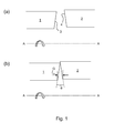
- Figure 1 (a) shows schematically a longitudinal cross-section through a pair of conventional tubular workpieces 1, 2 in readiness to undergo rotary friction welding.
- the workpieces are aligned on a common axis A-A and have respective end faces forming weld surfaces 3, 4.
- the left hand workpiece 1 is attached to a flywheel or drive system which is rotated at a predetermined speed, indicated by the solid arrow.
- the workpieces are brought together so that the weld surfaces 3, 4 make contact.
- the weld surfaces are not completely flat, and also not perpendicular to the axis A-A.
- the workpieces exhibit a diameter mismatch, eccentricities and/or axis misalignment. Accordingly, the weld surfaces meet at an angle ⁇ , and have an initial point of contact which is offset to the outer edge of the workpiece walls, producing a large gap G between the weld surfaces at their inner diameters. During the conditioning period, this results in a localised high pressure and hotspot at the point of contact.
- Figure 2 shows schematically plots of flywheel speed and workpiece upset against time for joining three nominally-identical conventional workpiece pairs. Due to variation in the contact conditions, the initial conditioning period where the upset is zero is highly variable, leading to significant differences in the final upsets achieved with the different pairs. Also, defect expulsion can be poorly controlled, particularly as the initial point of contact is offset to the outer edge of the weld surfaces.
- Figure 3(a) shows schematically a longitudinal cross-section through a pair of tubular workpieces 11, 12 according to an embodiment of the present invention.
- the workpieces are aligned on a common axis A-A, and are in readiness to undergo rotary friction welding, with the left hand workpiece 11 being attached to the flywheel.
- the end faces of the workpieces have respective annular projections 13, 14, at their end faces, with the outer 17, 19 and inner 18, 20 side faces of the projections tapering towards respective apex regions 15, 16 which form the weld surfaces.
- the weld surfaces 15, 16 may still not be completely flat, and not perpendicular to the axis A-A.
- the workpieces may still exhibit a diameter mismatch, eccentricities and/or axis misalignment.
- the weld surfaces still meet at an angle 0.
- the weld surfaces have an initial point of contact that is more centrally located relative to the workpiece walls, and a reduced gap G' between the weld surfaces 15, 16 at their inner diameters. Accordingly, control over the conditioning period is improved, reducing variability in the final offset that can be achieved.
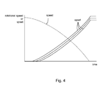
- Figure 4 shows schematically plots of flywheel speed and workpiece upset against time for joining three nominally-identical workpiece pairs according to an embodiment of the present invention. The upsets of Figure 4 can be compared with those of Figure 2 .
- the width of the left hand apex region 15 is narrower than that of the right hand weld surface 16.
- Typical workpiece diameters are controlled to +/-0.05 mm, and typical welding machine concentricity is controlled to within about 0.25 mm.
- the width of the narrow apex region is preferably at least about 0.6 or 0.7 mm less than the width of the facing weld surface. This ensures that the narrow apex region can always be made to contact the facing weld surface when brought into engagement, thus controlling the initial contact condition.
- the width of the narrowest apex region is preferably set such that the initial engagement force of the workpieces at the weld interface produces a contact pressure which is not greater than the respective plastic yield strengths of the materials of the workpieces.
- a reasonable minimum width of the apex region is 1 mm.
- the maximum width of the apex region may be no more than 70% and preferably no more than 60 or 50% of the wall thickness of the respective workpiece.
- the side surfaces 17, 18, 19, 20 of the annular projections 13, 14 may be angled ⁇ by at least 5° to the radial direction and/or at most 20° to the radial direction. These dimensions are consistent with controlling the conditioning period, and controlling defect expulsion.
- the annular projections promote efficient rejection of defects into flash during upsetting as expelled material does not have to travel laterally great distances in order to be removed from the weld interface. Further, such dimensions can help to create uniform isotherms at the contact area.
- the shape of the apex regions can also be adjusted, as necessary.
- the apex regions 15, 16 are shown with flat surfaces. Such surfaces may be perpendicular to the axis A-A, or tilted from the perpendicular.
- Another option, however, is to provide a convex apex region, which can be a smooth surface or a facetted surface.
- the shape of the apex regions can also be optimised for joining dissimilar materials. For example, if one workpiece is formed of a softer material than the other workpiece, then the relative widths of the apex regions 15, 16 and/or the relative sizes of the angles of the side surfaces 17, 18, 19, 20 may be adjusted to compensate. In particular, a workpiece formed of softer material may have larger side surface angles so that, due to its higher rate of upset, a more optimal weld interface shape and position is maintained.
Landscapes
- Engineering & Computer Science (AREA)
- Mechanical Engineering (AREA)
- General Engineering & Computer Science (AREA)
- Pressure Welding/Diffusion-Bonding (AREA)
Abstract
Description
- The present invention relates to a rotary friction welding process.
- Rotary friction welding is the process for welding together two bodies or workpieces by converting mechanical energy to heat energy by the friction between the engaging weld surfaces of the two workpieces. The process involves effecting relative rotation between the two workpieces while the weld surfaces remain in engagement with each other.
- For example, in inertia friction welding one of two coaxial workpieces is attached to a flywheel, rotated to a predetermined speed and then driven against the second workpiece using thrust supplied by the welding machine. A fixed amount of stored energy in the flywheel (proportional to rpm2.I, where rpm is the flywheel's predetermined speed and I is its rotational inertia) is thereby converted to heat by friction at the interface of the engaging weld surfaces, which bonds the workpieces together.
- The initial contact between the weld surfaces produces a conditioning period in which friction raises the temperature at the interface. This is followed by upsetting when the temperature reaches a high enough level such that softening/melting of the workpiece material allows the workpieces to be pushed together, with liquid or quasi-liquid material being expelled sideways from a plasticised zone at the interface.
- In its application to turbine hardware, such as the joining of compressor discs, the weld geometry is tubular. When using rotary friction welding to join two tubes together, it is standard practice for the starting weld surfaces to be flat and parallel end faces of the tubes.
- However, variations in contact conditions at the weld surfaces lead to variability in the welding process upset. For example, due to machining tolerances, residual stress distortions etc., the weld surfaces are generally not completely flat, which leads to non-axisymmetric contact, producing local hotspots at the weld interface. At large diameters in thin walled components such as turbine compressor discs, such non-uniform contact can be exaggerated. This results in variability in the efficiency of local heating during the conditioning period and hence variation in the conditioning duration. In the fixed-energy inertia welding process this leads to variation in total upset and hence fitness for purpose either through reduced integrity at low upset (interface contaminants not fully expelled) or component fit at low or high upset.
- Variations in contact conditions at the weld surfaces can also reduce control of defect expulsion. For example, the material may be expelled non-axisymmetrically from the interfacial plasticised zone, with a result that interface contaminants may not be fully removed from all parts of the weld. Accordingly, assumptions about flow and contaminant expulsion may be incorrect, leading to sub-optimal process and component design, or a low integrity product with a reduced life.
- As well as non-flat weld surfaces, contact condition variability may also be produced by workpiece diameter mismatch, workpiece eccentricity and lack of workpiece coaxiality. In addition, where a welding machine has a limited thrust capability this can compromise the preferred contact pressure for a given tubular wall thickness.
- It would be desirable to provide a rotary friction welding process which addresses at least the above problems.
- Accordingly, in a first aspect the present invention provides a rotary friction welding process including:
- providing a first tubular workpiece having a first weld surface at an end thereof, and a second tubular workpiece having a second weld surface at an end thereof,
- aligning the workpieces on a common axis with the weld surfaces facing each other, rotating one workpiece about the axis relative to the other workpiece, and engaging the first and second weld surfaces such that the rotation raises the temperature at the weld surfaces to create a weld interface, and
- ceasing the rotation and allowing the weld interface to cool to weld the workpieces together at the interface;
- wherein the first weld surface is an apex region of an annular projection at the end of the first workpiece, on a longitudinal section through the aligned workpieces the annular projection having a profile in which radially inner and outer side surfaces of the annular projection taper towards the apex region.
- Advantageously, by providing such an apex region, variability in the initial contact conditions at the weld surfaces can be reduced, leading to a more predictable conditioning period. As a result, upset variability can be reduced and defect expulsion improved. The process can thus be better optimised, for example allowing the amount of upset used to produce a given joint to be reduced, which can decrease material wastage through flash and/or decrease the amount of energy needed to produce the joint.
- More particularly, the apex region can lead to a smaller variation in pressure between inner and outer sides of the tube wall. The pressure at the weld interface is thus more uniform. Further, local hotspots can be reduced or eliminated and less time may be required to form a plasticised interface zone. In addition, the sideways (i.e. radial) distance for defects to be rejected into flash can be reduced, and detrimental effects of workpiece diameter mismatch, eccentricity and lack of coaxiality can be reduced or eliminated. In addition, an increased pressure during contact can be achieved, thereby promoting an initial rapid expulsion of interface contaminants and improving sealing of the weld against re-introduction of contaminants.
- In a second aspect, the present invention provides the first tubular workpiece of the process of the first aspect. For example, a tubular workpiece can be provided for use in a rotary friction welding process, the workpiece having a weld surface for engagement, on welding, with a corresponding weld surface of a further tubular workpiece, the weld surface being an apex region of an annular projection at the end of the workpiece, on a longitudinal section through the workpiece the annular projection having a profile in which radially inner and outer side surfaces of the annular projection taper towards the apex region.
- Optional features of the invention will now be set out. These are applicable singly or in any combination with any aspect of the invention.
- The process may be an inertia, direct drive, or hybrid rotary friction welding process.
- The tubular workpieces may be hollow cylindrical workpieces. However, the workpieces may have more complex shapes. In the case of a more complex shaped workpiece, typically the portion of the workpiece at the end having the weld surface is a hollow cylinder shape.
- The width of the apex region on the longitudinal section may be less than the width of the second weld surface on the longitudinal section. For example, for consistency with typical manufacturing tolerances, the width of the apex region on the longitudinal section may be at least 0.6 mm less than the width of the second weld surface on the longitudinal section, and preferably may be at least 0.7 mm less. The benefit of the apex region diminishes the wider the region becomes, and thus the width of the apex region on the longitudinal section may be less than 70%, and preferably less than 50%, of the wall thickness of the first workpiece. On the other hand very narrow apex regions can be susceptible to sudden collapse/failure on engagement of the weld surfaces, and thus the width of the apex region on the longitudinal section may be at least 1 mm.
- The apex region can be a flat surface. For example, it can be perpendicular to or at an angle to the axis. Another option, however, is for the apex region to be a convex surface, in which case it can be a smoothly convex surface or a facetted surface.
- The side surfaces of the annular projection may be angled by at least 5° to the radial direction and/or at most 20° to the radial direction. The angle of the side surfaces to the radial direction (which may be the angle labelled cp in
Figure 3(b) ) may be, for example, in the range of from 1° to 60°, for example 2° to 50°, for example 3° to 40°, for example 4° to 30°, for example 5° to 20°, for example on the order of 10° or 15°. - The second weld surface may be a second apex region of a second annular projection at the end of the second workpiece, on a longitudinal section through the aligned workpieces the second annular projection having a profile in which radially inner and outer side surfaces of the second annular projection taper towards the second apex region. Optional features of the first annular projection can apply to the second annular projection. For example, the width of the second apex region on the longitudinal section may be at most 70% and/or at least 1 mm. The second apex region can be a flat surface or a convex surface. The side surfaces of the second annular projection may be angled by at least 5° to the radial direction and/or at most 20° to the radial direction. When the workpieces are formed of dissimilar materials, the shapes of the first and second apex regions can be adjusted accordingly. For example, a workpiece formed of softer material than the other workpiece may have larger side surface angles. In this way, due to the higher rate of upset of the softer workpiece, a better weld interface shape and position can be maintained.
- The or each annular projection may be formed by machining the respective workpiece or by build-up of a suitable material by a material addition process.
- Embodiments of the invention will now be described by way of example with reference to the accompanying drawings in which:
-
Figure 1 shows schematically a longitudinal cross-section through a pair of conventional tubular workpieces (a) in readiness to undergo rotary friction welding, and (b) after being brought together so that their weld surfaces make contact; -
Figure 2 shows schematically plots of flywheel speed and workpiece upset against time for joining three nominally-identical conventional workpiece pairs; -
Figure 3 shows schematically a longitudinal cross-section through a pair of tubular workpieces according to an embodiment of the present invention (a) in readiness to undergo rotary friction welding, and (b) after being brought together so that their weld surfaces make contact; -
Figure 4 shows schematically plots of flywheel speed and workpiece upset against time for joining three nominally-identical workpiece pairs according to an embodiment of the present invention; and -
Figure 5 shows a relatively hard workpiece (at left) and relatively soft workpiece (at right) (a) with equal side surface angles and a resulting non-optimal weld interface shape and position, and (b) with non-equal side surface angles and a resulting improved weld interface shape and position. -
Figure 1 (a) shows schematically a longitudinal cross-section through a pair of conventionaltubular workpieces left hand workpiece 1 is attached to a flywheel or drive system which is rotated at a predetermined speed, indicated by the solid arrow. - As shown in
Figure 1 (b) , the workpieces are brought together so that the weld surfaces 3, 4 make contact. However, due to manufacturing tolerances, the weld surfaces are not completely flat, and also not perpendicular to the axis A-A. In addition, the workpieces exhibit a diameter mismatch, eccentricities and/or axis misalignment. Accordingly, the weld surfaces meet at an angle θ, and have an initial point of contact which is offset to the outer edge of the workpiece walls, producing a large gap G between the weld surfaces at their inner diameters. During the conditioning period, this results in a localised high pressure and hotspot at the point of contact. -
Figure 2 shows schematically plots of flywheel speed and workpiece upset against time for joining three nominally-identical conventional workpiece pairs. Due to variation in the contact conditions, the initial conditioning period where the upset is zero is highly variable, leading to significant differences in the final upsets achieved with the different pairs. Also, defect expulsion can be poorly controlled, particularly as the initial point of contact is offset to the outer edge of the weld surfaces. -
Figure 3(a) shows schematically a longitudinal cross-section through a pair oftubular workpieces left hand workpiece 11 being attached to the flywheel. In this case, however, the end faces of the workpieces have respectiveannular projections apex regions - Due to manufacturing tolerances, the weld surfaces 15, 16 may still not be completely flat, and not perpendicular to the axis A-A. In addition, the workpieces may still exhibit a diameter mismatch, eccentricities and/or axis misalignment. Thus, as shown in
Figure 3(b) , the weld surfaces still meet at an angle 0. However, by virtue of the annular projection on at least one of the workpieces, the weld surfaces have an initial point of contact that is more centrally located relative to the workpiece walls, and a reduced gap G' between the weld surfaces 15, 16 at their inner diameters. Accordingly, control over the conditioning period is improved, reducing variability in the final offset that can be achieved. This is illustrated inFigure 4 , which shows schematically plots of flywheel speed and workpiece upset against time for joining three nominally-identical workpiece pairs according to an embodiment of the present invention. The upsets ofFigure 4 can be compared with those ofFigure 2 . - As shown in
Figure 3 , the width of the lefthand apex region 15 is narrower than that of the righthand weld surface 16. Typical workpiece diameters are controlled to +/-0.05 mm, and typical welding machine concentricity is controlled to within about 0.25 mm. In view of these tolerances, the width of the narrow apex region is preferably at least about 0.6 or 0.7 mm less than the width of the facing weld surface. This ensures that the narrow apex region can always be made to contact the facing weld surface when brought into engagement, thus controlling the initial contact condition. - The benefit of the apex regions diminishes the wider the regions become relative to the wall thickness of the tubular workpieces. On the other hand, very narrow apex regions are at risk of collapse/failure due to plastic yielding. Accordingly, the width of the narrowest apex region is preferably set such that the initial engagement force of the workpieces at the weld interface produces a contact pressure which is not greater than the respective plastic yield strengths of the materials of the workpieces. For typical workpieces and friction welding equipment, a reasonable minimum width of the apex region is 1 mm. The maximum width of the apex region may be no more than 70% and preferably no more than 60 or 50% of the wall thickness of the respective workpiece. The side surfaces 17, 18, 19, 20 of the
annular projections - The shape of the apex regions can also be adjusted, as necessary. For example, in
Figure 3 , theapex regions - The shape of the apex regions can also be optimised for joining dissimilar materials. For example, if one workpiece is formed of a softer material than the other workpiece, then the relative widths of the
apex regions Figure 5 for a relativelyhard workpiece 11 and relatively soft workpiece 12 (a) with the workpieces having equal side surface angles and a resulting non-optimal weld interface shape and position, and (b) with the softer workpiece having larger side surface angles and a resulting improved weld interface shape and position. - While the invention has been described in conjunction with the exemplary embodiments described above, many equivalent modifications and variations will be apparent to those skilled in the art when given this disclosure. For example, only one of the
workpieces Figure 3 may have an annular projection. Accordingly, the exemplary embodiments of the invention set forth above are considered to be illustrative and not limiting. Various changes to the described embodiments may be made without departing from the scope of the invention.
Claims (11)
- A rotary friction welding process including:providing a first tubular workpiece (11) having a first weld surface (15) at an end thereof, and a second tubular workpiece (12) having a second weld surface (16) at an end thereof,aligning the workpieces on a common axis with the weld surfaces facing each other, rotating one workpiece about the axis relative to the other workpiece, and engaging the first and second weld surfaces such that the rotation raises the temperature at the weld surfaces to create a weld interface, andceasing the rotation and allowing the weld interface to cool to weld the workpieces together at the interface;wherein the first weld surface is an apex region (15) of an annular projection (13) at the end of the first workpiece, on a longitudinal section through the aligned workpieces the annular projection having a profile in which radially inner (18) and outer (17) side surfaces of the annular projection taper towards the apex region.
- A rotary friction welding process according to claim 1, wherein the width of the apex region on the longitudinal section is less than the width of the second weld surface on the longitudinal section.
- A rotary friction welding process according to claim 2, wherein the width of the apex region on the longitudinal section is at least 0.6 mm less than the width of the second weld surface on the longitudinal section.
- A rotary friction welding process according to claim 2 or 3, wherein the width of the apex region on the longitudinal section is less than 70% of the wall thickness of the first workpiece.
- A rotary friction welding process according to any one of the previous claims, wherein the width of the apex region on the longitudinal section is at least 1 mm.
- A rotary friction welding process according to any one of the previous claims, wherein the apex region is a flat surface.
- A rotary friction welding process according to any one of claims 1 to 5, wherein the apex region is a convex surface.
- A rotary friction welding process according to any one of the previous claims, wherein, on the longitudinal section, the side surfaces of the annular projection are angled by at least 5º to the radial direction.
- A rotary friction welding process according to any one of the previous claims, wherein, on the longitudinal section, the side surfaces of the annular projection are angled by at most 20º to the radial direction.
- A rotary friction welding process according to any one of the previous claims, wherein the second weld surface is a second apex region (16) of a second annular projection (14) at the end of the second workpiece, on a longitudinal section through the aligned workpieces the second annular projection having a profile in which radially inner (20) and outer (19) side surfaces of the second annular projection taper towards the second apex region.
- A tubular workpiece (11) for use in a rotary friction welding process, the workpiece having a weld surface (15) for engagement, on welding, with a corresponding weld surface (16) of a further tubular workpiece (12), the weld surface being an apex region (15) of an annular projection (13) at the end of the workpiece, on a longitudinal section through the workpiece the annular projection having a profile in which radially inner (18) and outer (17) side surfaces of the annular projection taper towards the apex region.
Applications Claiming Priority (1)
| Application Number | Priority Date | Filing Date | Title |
|---|---|---|---|
| GBGB1413923.2A GB201413923D0 (en) | 2014-08-06 | 2014-08-06 | Rotary friction welding |
Publications (2)
| Publication Number | Publication Date |
|---|---|
| EP2987583A1 true EP2987583A1 (en) | 2016-02-24 |
| EP2987583B1 EP2987583B1 (en) | 2019-07-24 |
Family
ID=51587811
Family Applications (1)
| Application Number | Title | Priority Date | Filing Date |
|---|---|---|---|
| EP15179509.3A Active EP2987583B1 (en) | 2014-08-06 | 2015-08-03 | Rotary friction welding of tubular workpieces |
Country Status (3)
| Country | Link |
|---|---|
| US (1) | US9791075B2 (en) |
| EP (1) | EP2987583B1 (en) |
| GB (1) | GB201413923D0 (en) |
Cited By (5)
| Publication number | Priority date | Publication date | Assignee | Title |
|---|---|---|---|---|
| EP3287225A1 (en) * | 2016-07-26 | 2018-02-28 | Rolls-Royce plc | Rotary friction welding process ; axisymmetric workpiece for use in such rotary friction welding process |
| CN107775184A (en) * | 2016-08-26 | 2018-03-09 | 劳斯莱斯有限公司 | Friction-welding technique |
| EP3292939A1 (en) * | 2016-07-26 | 2018-03-14 | Rolls-Royce plc | Rotary friction welding method ; corresponding rotor disc and rotor assembly |
| CN111112822A (en) * | 2020-01-03 | 2020-05-08 | 中国航空制造技术研究院 | A linear friction welding method |
| US11628514B2 (en) | 2019-06-13 | 2023-04-18 | Rolls-Royce Plc | Joining method |
Families Citing this family (8)
| Publication number | Priority date | Publication date | Assignee | Title |
|---|---|---|---|---|
| US10641159B2 (en) * | 2016-09-23 | 2020-05-05 | Caterpillar Inc. | Pre-chamber assembly for fuel injector |
| US20190039167A1 (en) * | 2017-08-01 | 2019-02-07 | United Technologies Corporation | Method of making integrally bladed rotor |
| JP7604489B2 (en) * | 2020-06-30 | 2024-12-23 | シチズン時計株式会社 | Machine tool and method for controlling machine tool |
| US11717911B1 (en) * | 2020-10-22 | 2023-08-08 | Paul Po Cheng | Method of fusing metal objects together |
| CN113857647B (en) * | 2021-11-01 | 2023-02-28 | 中国航空制造技术研究院 | A local damage repair method for thin-walled rotary structure |
| CN114060635B (en) * | 2021-11-15 | 2023-11-03 | 天津鹏翎集团股份有限公司 | Pipeline welded structure and pipeline assembly |
| DE102022211316A1 (en) * | 2022-10-25 | 2024-04-25 | Volkswagen Aktiengesellschaft | Rotor of an electrical machine and method for its manufacture |
| CN121798316A (en) * | 2026-03-10 | 2026-04-07 | 成都先进金属材料产业技术研究院股份有限公司 | Titanium alloy construction molding method and component |
Citations (2)
| Publication number | Priority date | Publication date | Assignee | Title |
|---|---|---|---|---|
| US3777360A (en) * | 1972-02-23 | 1973-12-11 | Gen Motors Corp | Friction welding process |
| FR2992880A1 (en) * | 2012-07-06 | 2014-01-10 | Snecma | PIECE FOR FRICTION WELDING |
Family Cites Families (10)
| Publication number | Priority date | Publication date | Assignee | Title |
|---|---|---|---|---|
| US3268248A (en) * | 1963-11-08 | 1966-08-23 | Douglas Aircraft Co Inc | Inter-locking welded joint |
| FR2123093B1 (en) | 1970-12-14 | 1974-03-22 | Unelec | |
| GB1361435A (en) * | 1972-11-15 | 1974-07-24 | Clarke Chapman John Thompson L | Friction welding annular parts |
| JPS5662687A (en) | 1979-10-25 | 1981-05-28 | Kawasaki Heavy Ind Ltd | Frictional pressure welding method |
| US4724975A (en) * | 1986-06-18 | 1988-02-16 | Cbi Research Corporation | High-pressure structure made of rings with peripheral weldments of reduced thickness |
| JPS6397381A (en) | 1986-10-09 | 1988-04-28 | Toyota Motor Corp | Friction welding method for thin wall pipe body |
| JP2000301364A (en) | 1999-04-12 | 2000-10-31 | Mitsuo Tsukada | Rotation friction agitation joining method of dissimiliar metal material |
| GB0400821D0 (en) * | 2004-01-15 | 2004-02-18 | Rolls Royce Plc | Friction welding process |
| GB0615671D0 (en) * | 2006-08-08 | 2006-09-13 | Rolls Royce Plc | A method of friction welding |
| WO2011163654A1 (en) * | 2010-06-25 | 2011-12-29 | Arcelormittal Investigacion Y Desarrollo, S.L. | Nickel-base radiant tube and method for making the same |
-
2014
- 2014-08-06 GB GBGB1413923.2A patent/GB201413923D0/en not_active Ceased
-
2015
- 2015-08-03 US US14/816,842 patent/US9791075B2/en active Active
- 2015-08-03 EP EP15179509.3A patent/EP2987583B1/en active Active
Patent Citations (2)
| Publication number | Priority date | Publication date | Assignee | Title |
|---|---|---|---|---|
| US3777360A (en) * | 1972-02-23 | 1973-12-11 | Gen Motors Corp | Friction welding process |
| FR2992880A1 (en) * | 2012-07-06 | 2014-01-10 | Snecma | PIECE FOR FRICTION WELDING |
Cited By (8)
| Publication number | Priority date | Publication date | Assignee | Title |
|---|---|---|---|---|
| EP3287225A1 (en) * | 2016-07-26 | 2018-02-28 | Rolls-Royce plc | Rotary friction welding process ; axisymmetric workpiece for use in such rotary friction welding process |
| EP3292939A1 (en) * | 2016-07-26 | 2018-03-14 | Rolls-Royce plc | Rotary friction welding method ; corresponding rotor disc and rotor assembly |
| US10625370B2 (en) | 2016-07-26 | 2020-04-21 | Rolls-Royce Plc | Rotary friction welding |
| US10632563B2 (en) | 2016-07-26 | 2020-04-28 | Rolls-Royce Plc | Rotary friction welding |
| CN107775184A (en) * | 2016-08-26 | 2018-03-09 | 劳斯莱斯有限公司 | Friction-welding technique |
| US11628514B2 (en) | 2019-06-13 | 2023-04-18 | Rolls-Royce Plc | Joining method |
| US11717915B2 (en) | 2019-06-13 | 2023-08-08 | Rolls-Royce Plc | Joining method |
| CN111112822A (en) * | 2020-01-03 | 2020-05-08 | 中国航空制造技术研究院 | A linear friction welding method |
Also Published As
| Publication number | Publication date |
|---|---|
| EP2987583B1 (en) | 2019-07-24 |
| US9791075B2 (en) | 2017-10-17 |
| GB201413923D0 (en) | 2014-09-17 |
| US20160039043A1 (en) | 2016-02-11 |
Similar Documents
| Publication | Publication Date | Title |
|---|---|---|
| US9791075B2 (en) | Rotary friction welding | |
| US10695821B2 (en) | Rivet for friction self-piercing riveting and friction self-piercing riveting connection system thereof | |
| TWI613024B (en) | Bonding method and method of manufacturing composite rolled material | |
| KR100576230B1 (en) | Apparatus and method for friction stir welding with a variable speed pin | |
| CN114012241B (en) | Friction welding method for revolving body component with closed cavity or closed channel | |
| JP5889741B2 (en) | Friction welding method of aluminum alloy propeller shaft | |
| EP3608031B1 (en) | Pipe elements | |
| US20140205369A1 (en) | Joint design welding dissimilar materials | |
| US10046414B2 (en) | Friction welding | |
| JP5701838B2 (en) | How to join a plastic workpiece to another workpiece | |
| WO2020129281A1 (en) | Joining method | |
| WO2019239623A1 (en) | Joining method and method for manufacturing composite rolled material | |
| US10632563B2 (en) | Rotary friction welding | |
| KR101756280B1 (en) | apparatus for friction stir welding | |
| JP5921858B2 (en) | Tripod type constant velocity universal joint and manufacturing method thereof | |
| JP7330886B2 (en) | Thread former and method of forming threads | |
| US10052715B2 (en) | Rotary friction welding | |
| JP2012240115A (en) | Rotary friction welding method and joined member | |
| JP6166999B2 (en) | Friction stir tool, friction stir welding apparatus, and friction stir welding method | |
| JP2015066574A5 (en) | ||
| WO2020213191A1 (en) | Joining method, and method for manufacturing composite rolled material | |
| JP2001330043A (en) | Shaft in which two pipe-shaped members are joined together and a joining method therefor |
Legal Events
| Date | Code | Title | Description |
|---|---|---|---|
| PUAI | Public reference made under article 153(3) epc to a published international application that has entered the european phase |
Free format text: ORIGINAL CODE: 0009012 |
|
| AK | Designated contracting states |
Kind code of ref document: A1 Designated state(s): AL AT BE BG CH CY CZ DE DK EE ES FI FR GB GR HR HU IE IS IT LI LT LU LV MC MK MT NL NO PL PT RO RS SE SI SK SM TR |
|
| AX | Request for extension of the european patent |
Extension state: BA ME |
|
| 17P | Request for examination filed |
Effective date: 20160727 |
|
| RBV | Designated contracting states (corrected) |
Designated state(s): AL AT BE BG CH CY CZ DE DK EE ES FI FR GB GR HR HU IE IS IT LI LT LU LV MC MK MT NL NO PL PT RO RS SE SI SK SM TR |
|
| STAA | Information on the status of an ep patent application or granted ep patent |
Free format text: STATUS: EXAMINATION IS IN PROGRESS |
|
| 17Q | First examination report despatched |
Effective date: 20170622 |
|
| GRAP | Despatch of communication of intention to grant a patent |
Free format text: ORIGINAL CODE: EPIDOSNIGR1 |
|
| STAA | Information on the status of an ep patent application or granted ep patent |
Free format text: STATUS: GRANT OF PATENT IS INTENDED |
|
| INTG | Intention to grant announced |
Effective date: 20190329 |
|
| GRAS | Grant fee paid |
Free format text: ORIGINAL CODE: EPIDOSNIGR3 |
|
| GRAA | (expected) grant |
Free format text: ORIGINAL CODE: 0009210 |
|
| STAA | Information on the status of an ep patent application or granted ep patent |
Free format text: STATUS: THE PATENT HAS BEEN GRANTED |
|
| AK | Designated contracting states |
Kind code of ref document: B1 Designated state(s): AL AT BE BG CH CY CZ DE DK EE ES FI FR GB GR HR HU IE IS IT LI LT LU LV MC MK MT NL NO PL PT RO RS SE SI SK SM TR |
|
| REG | Reference to a national code |
Ref country code: GB Ref legal event code: FG4D |
|
| REG | Reference to a national code |
Ref country code: CH Ref legal event code: EP |
|
| REG | Reference to a national code |
Ref country code: DE Ref legal event code: R096 Ref document number: 602015034168 Country of ref document: DE |
|
| REG | Reference to a national code |
Ref country code: AT Ref legal event code: REF Ref document number: 1157616 Country of ref document: AT Kind code of ref document: T Effective date: 20190815 |
|
| REG | Reference to a national code |
Ref country code: IE Ref legal event code: FG4D |
|
| REG | Reference to a national code |
Ref country code: NL Ref legal event code: MP Effective date: 20190724 |
|
| REG | Reference to a national code |
Ref country code: LT Ref legal event code: MG4D |
|
| REG | Reference to a national code |
Ref country code: AT Ref legal event code: MK05 Ref document number: 1157616 Country of ref document: AT Kind code of ref document: T Effective date: 20190724 |
|
| PG25 | Lapsed in a contracting state [announced via postgrant information from national office to epo] |
Ref country code: AT Free format text: LAPSE BECAUSE OF FAILURE TO SUBMIT A TRANSLATION OF THE DESCRIPTION OR TO PAY THE FEE WITHIN THE PRESCRIBED TIME-LIMIT Effective date: 20190724 Ref country code: NL Free format text: LAPSE BECAUSE OF FAILURE TO SUBMIT A TRANSLATION OF THE DESCRIPTION OR TO PAY THE FEE WITHIN THE PRESCRIBED TIME-LIMIT Effective date: 20190724 Ref country code: BG Free format text: LAPSE BECAUSE OF FAILURE TO SUBMIT A TRANSLATION OF THE DESCRIPTION OR TO PAY THE FEE WITHIN THE PRESCRIBED TIME-LIMIT Effective date: 20191024 Ref country code: NO Free format text: LAPSE BECAUSE OF FAILURE TO SUBMIT A TRANSLATION OF THE DESCRIPTION OR TO PAY THE FEE WITHIN THE PRESCRIBED TIME-LIMIT Effective date: 20191024 Ref country code: LT Free format text: LAPSE BECAUSE OF FAILURE TO SUBMIT A TRANSLATION OF THE DESCRIPTION OR TO PAY THE FEE WITHIN THE PRESCRIBED TIME-LIMIT Effective date: 20190724 Ref country code: PT Free format text: LAPSE BECAUSE OF FAILURE TO SUBMIT A TRANSLATION OF THE DESCRIPTION OR TO PAY THE FEE WITHIN THE PRESCRIBED TIME-LIMIT Effective date: 20191125 Ref country code: FI Free format text: LAPSE BECAUSE OF FAILURE TO SUBMIT A TRANSLATION OF THE DESCRIPTION OR TO PAY THE FEE WITHIN THE PRESCRIBED TIME-LIMIT Effective date: 20190724 Ref country code: SE Free format text: LAPSE BECAUSE OF FAILURE TO SUBMIT A TRANSLATION OF THE DESCRIPTION OR TO PAY THE FEE WITHIN THE PRESCRIBED TIME-LIMIT Effective date: 20190724 Ref country code: HR Free format text: LAPSE BECAUSE OF FAILURE TO SUBMIT A TRANSLATION OF THE DESCRIPTION OR TO PAY THE FEE WITHIN THE PRESCRIBED TIME-LIMIT Effective date: 20190724 |
|
| RAP2 | Party data changed (patent owner data changed or rights of a patent transferred) |
Owner name: ROLLS-ROYCE PLC |
|
| PG25 | Lapsed in a contracting state [announced via postgrant information from national office to epo] |
Ref country code: AL Free format text: LAPSE BECAUSE OF FAILURE TO SUBMIT A TRANSLATION OF THE DESCRIPTION OR TO PAY THE FEE WITHIN THE PRESCRIBED TIME-LIMIT Effective date: 20190724 Ref country code: LV Free format text: LAPSE BECAUSE OF FAILURE TO SUBMIT A TRANSLATION OF THE DESCRIPTION OR TO PAY THE FEE WITHIN THE PRESCRIBED TIME-LIMIT Effective date: 20190724 Ref country code: RS Free format text: LAPSE BECAUSE OF FAILURE TO SUBMIT A TRANSLATION OF THE DESCRIPTION OR TO PAY THE FEE WITHIN THE PRESCRIBED TIME-LIMIT Effective date: 20190724 Ref country code: IS Free format text: LAPSE BECAUSE OF FAILURE TO SUBMIT A TRANSLATION OF THE DESCRIPTION OR TO PAY THE FEE WITHIN THE PRESCRIBED TIME-LIMIT Effective date: 20191124 Ref country code: GR Free format text: LAPSE BECAUSE OF FAILURE TO SUBMIT A TRANSLATION OF THE DESCRIPTION OR TO PAY THE FEE WITHIN THE PRESCRIBED TIME-LIMIT Effective date: 20191025 Ref country code: ES Free format text: LAPSE BECAUSE OF FAILURE TO SUBMIT A TRANSLATION OF THE DESCRIPTION OR TO PAY THE FEE WITHIN THE PRESCRIBED TIME-LIMIT Effective date: 20190724 |
|
| PG25 | Lapsed in a contracting state [announced via postgrant information from national office to epo] |
Ref country code: TR Free format text: LAPSE BECAUSE OF FAILURE TO SUBMIT A TRANSLATION OF THE DESCRIPTION OR TO PAY THE FEE WITHIN THE PRESCRIBED TIME-LIMIT Effective date: 20190724 |
|
| PG25 | Lapsed in a contracting state [announced via postgrant information from national office to epo] |
Ref country code: IT Free format text: LAPSE BECAUSE OF FAILURE TO SUBMIT A TRANSLATION OF THE DESCRIPTION OR TO PAY THE FEE WITHIN THE PRESCRIBED TIME-LIMIT Effective date: 20190724 Ref country code: DK Free format text: LAPSE BECAUSE OF FAILURE TO SUBMIT A TRANSLATION OF THE DESCRIPTION OR TO PAY THE FEE WITHIN THE PRESCRIBED TIME-LIMIT Effective date: 20190724 Ref country code: EE Free format text: LAPSE BECAUSE OF FAILURE TO SUBMIT A TRANSLATION OF THE DESCRIPTION OR TO PAY THE FEE WITHIN THE PRESCRIBED TIME-LIMIT Effective date: 20190724 Ref country code: PL Free format text: LAPSE BECAUSE OF FAILURE TO SUBMIT A TRANSLATION OF THE DESCRIPTION OR TO PAY THE FEE WITHIN THE PRESCRIBED TIME-LIMIT Effective date: 20190724 Ref country code: RO Free format text: LAPSE BECAUSE OF FAILURE TO SUBMIT A TRANSLATION OF THE DESCRIPTION OR TO PAY THE FEE WITHIN THE PRESCRIBED TIME-LIMIT Effective date: 20190724 |
|
| PG25 | Lapsed in a contracting state [announced via postgrant information from national office to epo] |
Ref country code: MC Free format text: LAPSE BECAUSE OF FAILURE TO SUBMIT A TRANSLATION OF THE DESCRIPTION OR TO PAY THE FEE WITHIN THE PRESCRIBED TIME-LIMIT Effective date: 20190724 Ref country code: CH Free format text: LAPSE BECAUSE OF NON-PAYMENT OF DUE FEES Effective date: 20190831 Ref country code: CZ Free format text: LAPSE BECAUSE OF FAILURE TO SUBMIT A TRANSLATION OF THE DESCRIPTION OR TO PAY THE FEE WITHIN THE PRESCRIBED TIME-LIMIT Effective date: 20190724 Ref country code: LI Free format text: LAPSE BECAUSE OF NON-PAYMENT OF DUE FEES Effective date: 20190831 Ref country code: SM Free format text: LAPSE BECAUSE OF FAILURE TO SUBMIT A TRANSLATION OF THE DESCRIPTION OR TO PAY THE FEE WITHIN THE PRESCRIBED TIME-LIMIT Effective date: 20190724 Ref country code: SK Free format text: LAPSE BECAUSE OF FAILURE TO SUBMIT A TRANSLATION OF THE DESCRIPTION OR TO PAY THE FEE WITHIN THE PRESCRIBED TIME-LIMIT Effective date: 20190724 Ref country code: IS Free format text: LAPSE BECAUSE OF FAILURE TO SUBMIT A TRANSLATION OF THE DESCRIPTION OR TO PAY THE FEE WITHIN THE PRESCRIBED TIME-LIMIT Effective date: 20200224 Ref country code: LU Free format text: LAPSE BECAUSE OF NON-PAYMENT OF DUE FEES Effective date: 20190803 |
|
| REG | Reference to a national code |
Ref country code: BE Ref legal event code: MM Effective date: 20190831 |
|
| REG | Reference to a national code |
Ref country code: DE Ref legal event code: R097 Ref document number: 602015034168 Country of ref document: DE |
|
| PLBE | No opposition filed within time limit |
Free format text: ORIGINAL CODE: 0009261 |
|
| STAA | Information on the status of an ep patent application or granted ep patent |
Free format text: STATUS: NO OPPOSITION FILED WITHIN TIME LIMIT |
|
| PG2D | Information on lapse in contracting state deleted |
Ref country code: IS |
|
| PG25 | Lapsed in a contracting state [announced via postgrant information from national office to epo] |
Ref country code: IE Free format text: LAPSE BECAUSE OF NON-PAYMENT OF DUE FEES Effective date: 20190803 |
|
| 26N | No opposition filed |
Effective date: 20200603 |
|
| PG25 | Lapsed in a contracting state [announced via postgrant information from national office to epo] |
Ref country code: BE Free format text: LAPSE BECAUSE OF NON-PAYMENT OF DUE FEES Effective date: 20190831 Ref country code: SI Free format text: LAPSE BECAUSE OF FAILURE TO SUBMIT A TRANSLATION OF THE DESCRIPTION OR TO PAY THE FEE WITHIN THE PRESCRIBED TIME-LIMIT Effective date: 20190724 |
|
| PG25 | Lapsed in a contracting state [announced via postgrant information from national office to epo] |
Ref country code: CY Free format text: LAPSE BECAUSE OF FAILURE TO SUBMIT A TRANSLATION OF THE DESCRIPTION OR TO PAY THE FEE WITHIN THE PRESCRIBED TIME-LIMIT Effective date: 20190724 |
|
| PG25 | Lapsed in a contracting state [announced via postgrant information from national office to epo] |
Ref country code: HU Free format text: LAPSE BECAUSE OF FAILURE TO SUBMIT A TRANSLATION OF THE DESCRIPTION OR TO PAY THE FEE WITHIN THE PRESCRIBED TIME-LIMIT; INVALID AB INITIO Effective date: 20150803 Ref country code: MT Free format text: LAPSE BECAUSE OF FAILURE TO SUBMIT A TRANSLATION OF THE DESCRIPTION OR TO PAY THE FEE WITHIN THE PRESCRIBED TIME-LIMIT Effective date: 20190724 |
|
| PG25 | Lapsed in a contracting state [announced via postgrant information from national office to epo] |
Ref country code: MK Free format text: LAPSE BECAUSE OF FAILURE TO SUBMIT A TRANSLATION OF THE DESCRIPTION OR TO PAY THE FEE WITHIN THE PRESCRIBED TIME-LIMIT Effective date: 20190724 |
|
| P01 | Opt-out of the competence of the unified patent court (upc) registered |
Effective date: 20230528 |
|
| PGFP | Annual fee paid to national office [announced via postgrant information from national office to epo] |
Ref country code: DE Payment date: 20250827 Year of fee payment: 11 |
|
| PGFP | Annual fee paid to national office [announced via postgrant information from national office to epo] |
Ref country code: GB Payment date: 20250826 Year of fee payment: 11 |
|
| PGFP | Annual fee paid to national office [announced via postgrant information from national office to epo] |
Ref country code: FR Payment date: 20250825 Year of fee payment: 11 |