EP2987473B1 - Fluid collection and expulsion apparatus - Google Patents
Fluid collection and expulsion apparatus Download PDFInfo
- Publication number
- EP2987473B1 EP2987473B1 EP15185024.5A EP15185024A EP2987473B1 EP 2987473 B1 EP2987473 B1 EP 2987473B1 EP 15185024 A EP15185024 A EP 15185024A EP 2987473 B1 EP2987473 B1 EP 2987473B1
- Authority
- EP
- European Patent Office
- Prior art keywords
- fluid
- detection means
- reservoir
- times per
- level
- Prior art date
- Legal status (The legal status is an assumption and is not a legal conclusion. Google has not performed a legal analysis and makes no representation as to the accuracy of the status listed.)
- Not-in-force
Links
- 239000012530 fluid Substances 0.000 title claims description 228
- 238000001514 detection method Methods 0.000 claims description 78
- 238000000034 method Methods 0.000 claims description 8
- 239000003822 epoxy resin Substances 0.000 claims description 5
- 229920000647 polyepoxide Polymers 0.000 claims description 5
- 230000000007 visual effect Effects 0.000 claims description 4
- 238000005259 measurement Methods 0.000 description 32
- 210000002700 urine Anatomy 0.000 description 20
- 208000015181 infectious disease Diseases 0.000 description 7
- 230000003287 optical effect Effects 0.000 description 7
- 230000002485 urinary effect Effects 0.000 description 7
- 238000005086 pumping Methods 0.000 description 6
- 238000004891 communication Methods 0.000 description 5
- 206010046543 Urinary incontinence Diseases 0.000 description 4
- 238000010992 reflux Methods 0.000 description 4
- 230000005484 gravity Effects 0.000 description 3
- 238000012545 processing Methods 0.000 description 3
- 238000002834 transmittance Methods 0.000 description 3
- 230000013872 defecation Effects 0.000 description 2
- 210000003608 fece Anatomy 0.000 description 2
- 230000027939 micturition Effects 0.000 description 2
- 239000000203 mixture Substances 0.000 description 2
- 238000007789 sealing Methods 0.000 description 2
- 239000000243 solution Substances 0.000 description 2
- 238000004611 spectroscopical analysis Methods 0.000 description 2
- 208000005156 Dehydration Diseases 0.000 description 1
- 230000001133 acceleration Effects 0.000 description 1
- 239000000654 additive Substances 0.000 description 1
- 210000003423 ankle Anatomy 0.000 description 1
- 230000006931 brain damage Effects 0.000 description 1
- 231100000874 brain damage Toxicity 0.000 description 1
- 208000029028 brain injury Diseases 0.000 description 1
- 230000003749 cleanliness Effects 0.000 description 1
- 150000001875 compounds Chemical group 0.000 description 1
- 230000018044 dehydration Effects 0.000 description 1
- 238000006297 dehydration reaction Methods 0.000 description 1
- 230000000694 effects Effects 0.000 description 1
- 238000007667 floating Methods 0.000 description 1
- 239000000383 hazardous chemical Substances 0.000 description 1
- 238000001802 infusion Methods 0.000 description 1
- 238000010253 intravenous injection Methods 0.000 description 1
- 239000007788 liquid Substances 0.000 description 1
- 230000007774 longterm Effects 0.000 description 1
- 238000004519 manufacturing process Methods 0.000 description 1
- 239000000463 material Substances 0.000 description 1
- 238000012544 monitoring process Methods 0.000 description 1
- 239000004033 plastic Substances 0.000 description 1
- 230000002265 prevention Effects 0.000 description 1
- 238000011084 recovery Methods 0.000 description 1
- 239000000523 sample Substances 0.000 description 1
- 230000035945 sensitivity Effects 0.000 description 1
- 230000011664 signaling Effects 0.000 description 1
- 239000000126 substance Chemical group 0.000 description 1
- 239000002699 waste material Substances 0.000 description 1
Images

Classifications
-
- A—HUMAN NECESSITIES
- A61—MEDICAL OR VETERINARY SCIENCE; HYGIENE
- A61M—DEVICES FOR INTRODUCING MEDIA INTO, OR ONTO, THE BODY; DEVICES FOR TRANSDUCING BODY MEDIA OR FOR TAKING MEDIA FROM THE BODY; DEVICES FOR PRODUCING OR ENDING SLEEP OR STUPOR
- A61M1/00—Suction or pumping devices for medical purposes; Devices for carrying-off, for treatment of, or for carrying-over, body-liquids; Drainage systems
- A61M1/80—Suction pumps
-
- F—MECHANICAL ENGINEERING; LIGHTING; HEATING; WEAPONS; BLASTING
- F04—POSITIVE - DISPLACEMENT MACHINES FOR LIQUIDS; PUMPS FOR LIQUIDS OR ELASTIC FLUIDS
- F04D—NON-POSITIVE-DISPLACEMENT PUMPS
- F04D7/00—Pumps adapted for handling specific fluids, e.g. by selection of specific materials for pumps or pump parts
- F04D7/02—Pumps adapted for handling specific fluids, e.g. by selection of specific materials for pumps or pump parts of centrifugal type
-
- A—HUMAN NECESSITIES
- A61—MEDICAL OR VETERINARY SCIENCE; HYGIENE
- A61B—DIAGNOSIS; SURGERY; IDENTIFICATION
- A61B5/00—Measuring for diagnostic purposes; Identification of persons
- A61B5/20—Measuring for diagnostic purposes; Identification of persons for measuring urological functions restricted to the evaluation of the urinary system
- A61B5/207—Sensing devices adapted to collect urine
- A61B5/208—Sensing devices adapted to collect urine adapted to determine urine quantity, e.g. flow, volume
-
- A—HUMAN NECESSITIES
- A61—MEDICAL OR VETERINARY SCIENCE; HYGIENE
- A61F—FILTERS IMPLANTABLE INTO BLOOD VESSELS; PROSTHESES; DEVICES PROVIDING PATENCY TO, OR PREVENTING COLLAPSING OF, TUBULAR STRUCTURES OF THE BODY, e.g. STENTS; ORTHOPAEDIC, NURSING OR CONTRACEPTIVE DEVICES; FOMENTATION; TREATMENT OR PROTECTION OF EYES OR EARS; BANDAGES, DRESSINGS OR ABSORBENT PADS; FIRST-AID KITS
- A61F5/00—Orthopaedic methods or devices for non-surgical treatment of bones or joints; Nursing devices ; Anti-rape devices
- A61F5/44—Devices worn by the patient for reception of urine, faeces, catamenial or other discharge; Colostomy devices
- A61F5/4404—Details or parts
-
- G—PHYSICS
- G01—MEASURING; TESTING
- G01F—MEASURING VOLUME, VOLUME FLOW, MASS FLOW OR LIQUID LEVEL; METERING BY VOLUME
- G01F23/00—Indicating or measuring liquid level or level of fluent solid material, e.g. indicating in terms of volume or indicating by means of an alarm
- G01F23/80—Arrangements for signal processing
-
- A—HUMAN NECESSITIES
- A61—MEDICAL OR VETERINARY SCIENCE; HYGIENE
- A61B—DIAGNOSIS; SURGERY; IDENTIFICATION
- A61B5/00—Measuring for diagnostic purposes; Identification of persons
- A61B5/05—Detecting, measuring or recording for diagnosis by means of electric currents or magnetic fields; Measuring using microwaves or radio waves
- A61B5/053—Measuring electrical impedance or conductance of a portion of the body
-
- A—HUMAN NECESSITIES
- A61—MEDICAL OR VETERINARY SCIENCE; HYGIENE
- A61B—DIAGNOSIS; SURGERY; IDENTIFICATION
- A61B5/00—Measuring for diagnostic purposes; Identification of persons
- A61B5/74—Details of notification to user or communication with user or patient; User input means
- A61B5/7405—Details of notification to user or communication with user or patient; User input means using sound
-
- A—HUMAN NECESSITIES
- A61—MEDICAL OR VETERINARY SCIENCE; HYGIENE
- A61F—FILTERS IMPLANTABLE INTO BLOOD VESSELS; PROSTHESES; DEVICES PROVIDING PATENCY TO, OR PREVENTING COLLAPSING OF, TUBULAR STRUCTURES OF THE BODY, e.g. STENTS; ORTHOPAEDIC, NURSING OR CONTRACEPTIVE DEVICES; FOMENTATION; TREATMENT OR PROTECTION OF EYES OR EARS; BANDAGES, DRESSINGS OR ABSORBENT PADS; FIRST-AID KITS
- A61F5/00—Orthopaedic methods or devices for non-surgical treatment of bones or joints; Nursing devices ; Anti-rape devices
- A61F5/44—Devices worn by the patient for reception of urine, faeces, catamenial or other discharge; Colostomy devices
- A61F2005/4402—Devices worn by the patient for reception of urine, faeces, catamenial or other discharge; Colostomy devices disposable
-
- A—HUMAN NECESSITIES
- A61—MEDICAL OR VETERINARY SCIENCE; HYGIENE
- A61M—DEVICES FOR INTRODUCING MEDIA INTO, OR ONTO, THE BODY; DEVICES FOR TRANSDUCING BODY MEDIA OR FOR TAKING MEDIA FROM THE BODY; DEVICES FOR PRODUCING OR ENDING SLEEP OR STUPOR
- A61M2209/00—Ancillary equipment
- A61M2209/08—Supports for equipment
- A61M2209/088—Supports for equipment on the body
-
- Y—GENERAL TAGGING OF NEW TECHNOLOGICAL DEVELOPMENTS; GENERAL TAGGING OF CROSS-SECTIONAL TECHNOLOGIES SPANNING OVER SEVERAL SECTIONS OF THE IPC; TECHNICAL SUBJECTS COVERED BY FORMER USPC CROSS-REFERENCE ART COLLECTIONS [XRACs] AND DIGESTS
- Y10—TECHNICAL SUBJECTS COVERED BY FORMER USPC
- Y10T—TECHNICAL SUBJECTS COVERED BY FORMER US CLASSIFICATION
- Y10T137/00—Fluid handling
- Y10T137/8158—With indicator, register, recorder, alarm or inspection means
- Y10T137/8342—Liquid level responsive indicator, recorder or alarm
Definitions
- the present invention relates to fluid collection and expulsion apparatus and particularly, although not exclusively, where the fluid is one produced by a person, such as urine.
- Urinary incontinence can affect a wide range of people.
- many stroke victims suffer from urinary incontinence as a result of partial brain damage caused by their stroke.
- the individual may be otherwise healthy and urinary incontinence can severely restrict their lifestyle, not to mention be a cause of personal embarrassment.
- Leg bag systems typically comprise a urine bag that straps to the individual's leg and is connected by tubing to a catheter or other urine collection device worn by the individual.
- the urine bag has an outlet having a tap or valve for the individual or medical staff to empty the bag through.
- the outlet tap or valve is down by the individual's ankle making it difficult for some individuals to access if they are elderly or less physically able, for example. In these situations, another person such as a carer or family member must operate the tap or valve to empty the bag. This results in a loss of independence and possibly a loss of dignity for the individual.
- leg bag users are reluctant to take in fluids, i.e. they drink less to avoid filling the bag frequently. This is not conducive to infection prevention.
- patients who are recovering from illness tend to suffer from dehydration, so reluctance to intake fluid will hinder their recovery.
- a leg bag system that addresses some of these problems is described in the application WO-A-03/055423 (Wills, Trevor).
- the system comprises a leg bag having sensing means for detecting a fluid level in the bag and processing means for processing information received by the sensing means.
- the system further comprises signaling means for alerting the user when the fluid reaches a predetermined level, so that the user can empty the contents of the bag before it becomes too full.
- the system further comprises a pump facilitating emptying of the bag via an upper outlet obviating the need for the individual to bend down and access a gravity-driven outlet tap or valve below the bag.
- leg bags need to be replaced at regular intervals. For example, to reduce the risk of infection but not prove too much of an inconvenience, typical leg bags may be replaced every seven days.
- Leg bags utilizing electronic means such as sensors, controllers and pumps also require a power source to operate.
- a portable power source such as one or more batteries is appropriate.
- Rechargeable batteries are particularly suitable.
- the batteries are able to power the electronic components for at least as long as a single bag is being used (e.g. seven days), before replacement or recharging of the batteries is required.
- leg bags using standard pumps such as centrifugal pumps, draw too much current to be powered by a single battery power source over a seven day period. If smaller, less-current draining standard pumps are used, the required pumping pressure is not achieved to sufficiently eject fluid upward from the bag through an outlet.
- Level detection may be done by electromechanical means, such as a floating component at the surface of the fluid which contacts an electrical contact at a set level within the bag.
- electromechanical measurement means are commonly large and cumbersome which is not desirable in a leg bag that seeks to be as small and discreet as possible. Additionally, the presence of moving parts has associated manufacturing and assembly costs and may also give rise to reliability issues in the device.
- Alternative leg bags use sensors to detect the fluid level by measuring a property of the urine, such as resistance, to ascertain the total volume.
- the composition e.g. material content and concentration
- a further consideration regarding the accuracy of measurement is the possibility of a moving fluid within the bag causing the level measurement means to falsely indicate that the bag requires emptying. This may arise as a result of the individual walking or otherwise moving with the leg bag attached to them. Clearly, false readings and subsequent false alarms would be inconvenient and irritating to the user.
- US-A-5135485 (Cohen et al. ) describes a capacitance-type fluid level sensing system, method and device for determining the amount of fluid in a container, for example, a disposable plastic bag used for intravenous injection or collection of waste from a human body.
- WO-A-00/37129 (Alcor Medical Instruments) describes a method and system for the automatic monitoring and control of patient fluid balance.
- the described system comprises an infusion bag and urine collection bag whose volumes are monitored by means of electrodes attached to the bags.
- WO-A-20009/142508 (Bonvik, Knut) describes a system for real time long-term recording and/or real time spectroscopy of a discharged urine amount from a patient.
- a registration unit is provided that includes one or more light sources and one or more sensor means for optical real time reading/registration of urine volume and/or real time spectroscopy of the urine volume.
- EP-A-2243448 (Uni Charm Corp and Hitachi Ltd) describes an automatic urine disposal apparatus adapted to detect the presence of faeces in a wide range.
- a detector unit has a urination detector and a defecation detector.
- the urination detector comprises a pair of first electrodes and the defecation detector comprises a pair of second electrodes.
- the pair of first electrodes and the pair of second electrodes each have regions spaced one from another and extending in parallel one to another and these regions comprise portions that can be wetted with urine or moisture contained in faeces.
- a centrifugal pump for use with a portable fluid collection apparatus for collecting fluid produced by a person, the centrifugal pump comprising:
- the inner diameter of the pump chamber is equal to or less than 1.50 times the outer diameter of the impeller. In a further or alternative preferable arrangement, the inner diameter of the pump chamber is substantially equal to or greater than 1.42 times the outer diameter of the impeller. In a particularly preferable arrangement, the inner diameter of the pump chamber is between 1.42 and 1.45 times the outer diameter of the impeller, inclusive, or is between 1.42 and 1.43 times the outer diameter of the impeller, inclusive.
- the impeller preferably comprises a central spindle rotatably mounted on said driveshaft, and a plurality of circumferentially spaced blades extending radially from said central spindle, wherein said outer diameter of said impeller is the largest dimension of the impeller in a direction substantially perpendicular to said driveshaft.
- a longitudinal axis of said fluid outlet is preferably arranged substantially perpendicularly relative to a longitudinal axis of said fluid inlet and radially aligned with said impeller.
- a portable fluid collection apparatus comprising:
- the portable fluid collection apparatus preferably further comprises an outlet conduit in fluid communication with the fluid outlet of said pump, and/or further preferably comprises a battery for powering said pump via driving means.
- said fluid reservoir is disposable and/or said pump is disposable.
- the portable fluid collection apparatus preferably further comprises detection means for detecting a property of fluid within the fluid reservoir, wherein said detection means preferably comprise means for measuring a property of fluid between a first position and a second position spaced from said first position.
- said detection means further comprises means for measuring a property of fluid between said first position and a third position, where the distance between said first position and said third position is less than the distance between said first position and said second position.
- Said detection means preferably comprises means for measuring an electrical or optical property of fluid, and preferably comprises means for measuring one or more of electrical resistance, capacitance, electrical resonance and optical transmittance of fluid.
- said second position is located so as to come into contact with fluid when the fluid reservoir contains a volume of fluid that is between 55% and 75% of its maximum capacity, and preferably between 60% and 70% of its maximum capacity, and further preferably between 64% and 68% of its maximum capacity. Further preferably, said second position is located so as to come into contact with fluid when the fluid reservoir contains a volume of fluid that is about 66% of its maximum capacity.
- the portable fluid collection preferably further comprises processor means configured to receive data from the detection means and determine the level of fluid within the fluid reservoir, and signal means for producing an audible, visual, or tactile signal, wherein said processor means is configured to activate said signal means to produce said signal when the determined level of fluid within the fluid reservoir exceeds a predetermined threshold.
- Said processor means are preferably configured to calibrate measured data corresponding to a property of fluid between said first position and said second position using measured data corresponding to a property of fluid between said first position and said third position in order to determine the level of fluid within the fluid reservoir.
- said processor means are configured to receive a data packet from the detection means a plurality of times per second and is further configured to only activate said signal means to produce a signal when said processor means determines that the level of fluid within the fluid reservoir exceeds said predetermined threshold over a predetermined number of successive data packets.
- said processor means are configured to receive a data packet from the detection means 15 times per second or more, and/or wherein said predetermined number of successive data packets is between 15 and 45, and preferably 30.
- said processor means are configured to receive a data packet from the detection means 100 times per second, 125 time per second, 256 times per second, or more.
- Said detection means preferably comprise one or more electrical wires for connecting said detection means to a power source and/or said processor means, and wherein said one or more wires pass out from the inside of said reservoir to the outside of said reservoir through an outlet fitting having a bore, wherein a seal around the one or more wires in the bore is formed by a heat shrinkable sleeve sheathing the one or more wires and a heat cured epoxy resin.
- said detection means preferably comprise one or more electrical wires for connecting said detection means to a power source and/or said processor means, and wherein said one or more wires pass out from the inside of said reservoir to the outside of said reservoir through an outlet fitting having a bore, wherein a seal around the one or more wires in the bore is formed by an elastomeric sleeve sheathing the one or more wires.
- a portable fluid collection apparatus comprising:
- the portable fluid collection apparatus preferably further comprises processor means configured to receive data from the detection means and determine the level of fluid within the fluid reservoir, said processor means being further configured to calibrate measured data corresponding to a property of fluid between said first position and said second position using measured data corresponding to a property of fluid between said first position and said third position in order to determine the level of fluid within the fluid reservoir.
- the portable fluid collection apparatus further comprises signal means for producing an audible, visual, or tactile signal, wherein said processor means is configured to activate said signal means to produce said signal when the determined level of fluid within the fluid reservoir exceeds a predetermined threshold.
- Said detection means preferably comprises means for measuring an electrical or optical property of fluid and preferably comprises means for measuring one or more of electrical resistance, capacitance, electrical resonance and optical transmittance of fluid.
- Said second position is preferably located so as to come into contact with fluid when the fluid reservoir contains a volume of fluid that is between 55% and 75% of its maximum capacity, and preferably between 60% and 70% of its maximum capacity, and further preferably between 64% and 68% of its maximum capacity.
- said second position is located so as to come into contact with fluid when the fluid reservoir contains a volume of fluid that is about 66% of its maximum capacity.
- Said processor means are preferably configured to receive a data packet from the detection means a plurality of times per second and is further configured to only activate said signal means to produce a signal when said processor means determines that the level of fluid within the fluid reservoir exceeds said predetermined threshold over a predetermined number of successive data packets.
- said processor means are configured to receive a data packet from the detection means 15 times per second or more and/or wherein said predetermined number of successive data packets is between 15 and 45, and preferably 30.
- said processor means are preferably configured to receive a data packet from the detection means 100 times per second, 125 times per second, 256 times per second, or more.
- Said detection means preferably comprise one or more electrical wires for connecting said detection means to a power source and/or said processor means, and wherein said one or more wires pass out from the inside of said reservoir to the outside of said reservoir through an outlet fitting having a bore, wherein a seal around the one or more wires in the bore is formed by a heat shrinkable sleeve sheathing the one or more wires and a heat cured epoxy resin.
- said detection means preferably comprise one or more electrical wires for connecting said detection means to a power source and/or said processor means, and wherein said one or more wires pass out from the inside of said reservoir to the outside of said reservoir through an outlet fitting having a bore, wherein a seal around the one or more wires in the bore is formed by an elastomeric sleeve sheathing the one or more wires.
- the processor means are preferably configured to receive a data packet from the detection means 15 times per second or more, and/or wherein said predetermined number of successive data packets is between 15 and 45, and preferably 30.
- said processor means are preferably configured to receive a data packet from the detection means 100 times per second, 125 times per second, 256 times per second, or more.
- said detection means comprise one or more electrical wires for connecting said detection means to a power source and/or said processor means, and wherein said one or more wires pass out from the inside of said reservoir to the outside of said reservoir through an outlet fitting having a bore, wherein a seal around the one or more wires in the bore is formed by a heat shrinkable sleeve sheathing the one or more wires and a heat cured epoxy resin.
- said detection means preferably comprise one or more electrical wires for connecting said detection means to a power source and/or said processor means, and wherein said one or more wires pass out from the inside of said reservoir to the outside of said reservoir through an outlet fitting having a bore, wherein a seal around the one or more wires in the bore is formed by an elastomeric sleeve sheathing the one or more wires.
- a method of controlling a portable fluid collection apparatus comprising:
- using the processor means to receive a data packet from the detection means (40) may comprise receiving a data packet from the detection means (40) 15 times per second or more 15 times per second or more, and/or wherein said predetermined number of successive data packets is between 15 and 45, and preferably 30.
- using the processor means to receive a data packet from the detection means (40) may comprise receiving a data packet from the detection means (40) 100 times per second, 125 times per second, 256 times per second, or more.
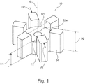
- FIG 1 shows a detailed view of an impeller 10 of a centrifugal pump 20 which is shown in Figure 2 .
- the impeller 10 comprises a central spindle 12 having a central hole 12a through which a drive shaft 22 (see Figure 2 ) may be disposed to rotatably mount the impeller 10 thereon.
- the impeller 10 has a central axis 16 which is parallel to the drive shaft 22 when rotatably mounted thereon.
- the central spindle 12 has a diameter D1 and an axial height H1.
- the impeller 10 has a plurality of circumferentially spaced blades 14 extending radially from the central spindle 12.
- the impellor has six blades 14 that each extend in a radial direction without any circumferential bend.
- other configurations of blades are envisaged, such as blades that do extend radially with a circumferential bend (e.g. "spiral" blades).
- the blades 14 define an outer diameter D2 of the impeller 10 and have an axial height dimension, H2.
- the axial height H2 of the blades 14 is greater than the axial height H1 of the central spindle 12, although this need not necessarily be the case in other arrangements.
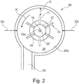
- the impeller 10 when assembled as part of the centrifugal pump 20, the impeller 10 is rotatably mounted on a driveshaft 22 within a pump chamber 26.
- the driveshaft 22 is connected to driving means (not shown), such as a motor, to rotate the driveshaft 22 and, in turn, rotate the impeller 10 in the direction indicated in Figure 2 by arrow R.
- the pump chamber 26 is generally cylindrical and is defined by a pump chamber wall 26a.
- the pump chamber wall 26a has an inner diameter D3 that is greater than the outer diameter D2 of the impeller 10 so as to completely envelope the impeller 10.
- the pump chamber 26 is fluidly connected to a fluid inlet 24 and a fluid outlet 28, where the fluid inlet is centered on and substantially parallel to the central axis 16 of the impeller 10.
- the fluid outlet 28 is arranged perpendicularly relative to the fluid inlet 24 and is radially aligned with said impeller 10 such that fluid flowing into the pump chamber 26 through fluid inlet 24 is accelerated by rotating blades 14 of the impeller 10 and passes out of the fluid outlet 28.
- the rotating impeller 10 experiences fluidic drag as it rotates in the fluid within the pump chamber 26.
- a result of fluidic drag is that more current (i.e. more electrical power) is required to rotate the impeller 10 to produce a certain pumping pressure as compared to an ideal, drag free system that is otherwise identical. Thus, more electrical power is consumed than would be if fluidic drag was non-existent or of less effect.
- the ratio of the outer diameter D2 of the impeller 10 relative to the inner diameter D3 of the pump chamber 26 is such that fluidic drag is reduced but the required pumping pressure can still be achieved (through acceleration of the fluid by the impeller 10).
- the fluidic drag is reduced such that the pump can be powered by a single portable power source, such as a battery pack, without the requirement of charging or replacing the power source for a desired period of time, such as seven days or more.
- the pump 20 may be required to pump 500 ml of liquid vertically upward through a vertical tube of 1.5 m in 1 minute or less so that a user of a urinary leg bag can empty the contents of the bag without the need to bend down and open a tap or valve to allow gravity-driven expulsion of fluid.
- the pumping pressure for achieving these desirable conditions can be met using a power source, such as a battery, that does not require charging or replacing within a period of less than seven days.
- the inner diameter D3 of the pump chamber 26 may be substantially equal to or greater than 1.40 times the outer diameter D2 of the impeller 10.
- the inner diameter D3 of the pump chamber 26 is preferably between 12 and 16 mm, and is further preferably 14 mm. In a preferable embodiment, the inner diameter D3 of the pump chamber 26 is substantially equal to or less than 1.50 times the outer diameter D2 of the impeller 10.
- the inner diameter D3 of the pump chamber 26 is substantially equal to or greater than 1.42 times the outer diameter D2 of the impeller 10, and is preferably between 1.42 and 1.45 times the outer diameter D2 of the impeller 10, or further preferably between 1.42 and 1.43 times the outer diameter D2 of the impeller 10.
- the inner diameter D3 of the pump chamber 26 may be 14 mm and the outer diameter D2 of the impeller 10 may be between 9.80 and 9.86 mm, inclusive.
- the central spindle 12 has a diameter D1 of about 4.89 mm and an axial height H1 of about 2.76 mm and/or the blades 14 have an axial height H2 of about 4.21 mm.
- the pump 20 may have a clearance C such that fluidic drag is reduced thereby reducing the electrical demands of the pump 20, without impairing the pump's pumping ability below the threshold for correct operation as part of a urinary leg bag system.
- the fluid inlet 24 of the pump 20 may be connected to a fluid reservoir (not shown) and the fluid outlet 28 is connected to an outlet conduit (not shown) which may be tubing which can be held, manipulated and directed by a user to control the expulsion of fluid whilst the pump is operating.
- the outlet conduit may be about 1.5 m in length and may be oriented substantially vertically upwards relative to the pump 20, in use.
- the system may additionally comprise any features of known leg bag systems, such as the features described in WO-A-03/055423 (Wills, Trevor).
- additional features may include fluid detection means to measure the level of fluid within the bag, processor means for processing data from the detection means, and signal means for alerting the user when the detected level of fluid reaches or exceeds a predetermined level.
- the bag and/or pump 20 may be disposable such that it can be thrown away after a given time interval, such as seven days, to reduce infection risk. This supports a system where a battery can provide the required electrical power to the system over a seven day period. Variations of pump dimensions within the scope of the present invention permit pumps that can be supported over different time periods by a single portable power source to be realized.
- the battery may be conveniently recharged or replaced at the same time as changing the bag and/or pump 20.
- the pump 20 may be integral with the bag such that the two are disposable together.
- the battery is rechargeable so as to reduce the disposal of hazardous materials commonly found in batteries.
- the pump 20 may be cleanable so that hygiene can be maintained without the need to regularly dispose of the pump 20.
- an improved fluid detection system for use on or in a fluid reservoir.
- the fluid reservoir forms part of a portable fluid collection apparatus for receiving fluid produced by a person, such as a urinary leg bag system, although the improved detection system may be equally applicable to other fluid reservoirs.
- Detection means are provided for detecting a property of fluid within the fluid reservoir, where the detection means has means for measuring a property of fluid between a first position and a second position spaced from said first position.
- the detection means further has means for measuring a property of fluid between the first position and a third position. The distance between the first position and the third position is less than the distance between the first position and the second position.
- Processor means are provided that are configured to receive data from the detection means and determine the level of fluid within the fluid reservoir.
- the processor means may be further configured to calibrate measured data corresponding to a property of the fluid between the first position and the second position using measured data corresponding to a property of the fluid between the first position and the third position in order to determine the level of fluid within the fluid reservoir.
- the first position is located at a lower part of the fluid reservoir, such as proximate to an outlet of the reservoir.
- the second position is chosen to be at a level that is equal to the level of fluid when the fluid reaches a threshold volume within the reservoir (i.e. a "threshold level"), above which reflux and infection become a significant possibility.
- a threshold volume within the reservoir i.e. a "threshold level”
- a fluid reservoir filled with fluid to a volume of 66% of the maximum capacity of the reservoir is considered to be a suitable threshold level which should not be exceeded if reflux and infections are to be avoided.
- the detection means measure a property of fluid between the first and second positions. This may be done using electrodes or other suitable measurement apparatus, such as emitters and receivers, located at each of the first and second positions.
- the measurement between the first and second positions should change depending on whether the first and second positions are connected to one another by fluid or not. That is, there should be a measurable difference between the first and second positions when the volume of fluid is such that it covers the first and second positions, and when it covers only one or neither of the positions.
- measureable properties of fluids in particular urine, depend upon the given fluid's composition and concentration. In the case of urine, measurable electrical resistance will depend upon what the individual has had to eat or drink prior to passing the urine, among other variables.
- the measurable difference between the case where urine does not link the first and second positions and the case where it does may, in some cases, be slight, and possibly not defined enough to reliably and repeatedly determine that the urine has filled the reservoir enough to reach the second position.
- measurement between the first and third position is used to improve the accuracy of the determination of fluid level from data of measurements between the first and second positions, by calibration.
- the first and third positions are spaced closer to one another than the first and second positions. Therefore, the amount of fluid required to connect the first position to the third position will be less than the amount of fluid required to connect the first position to the second position. Over a smaller distance, measureable changes between a fluidly linked condition and a non-fluidly linked condition are more pronounced and reliable.
- first and second positions should be located close to one another close to the desired threshold level (e.g. around 66% of maximum capacity), however use of close first and second positions may give rise to false readings if fluid within the reservoir was to slosh around and fluidly connect the positions despite the volume of fluid being below the desired threshold level. This is not a problem for the first and third positions if they are located such that it is highly likely that they will both be submerged in fluid, even at low volumes. Indeed, if the first and third positions are close to the bottom of the reservoir, gravity will ensure that even low volumes of fluid are able to fluidly connect the first and third positions so as to be measurable.
- the desired threshold level e.g. around 66% of maximum capacity
- the processor means can determine what sensitivity to operate at when attempting to establish whether measurements of the fluid between the first and second position are indicative of fluid connection or not (i.e. whether the volume of fluid within the reservoir is at the threshold level or not).
- the detection means may measure an electrical or optical property of the fluid which may be one or more properties selected from the non-exhaustive list comprising electrical resistance, capacitance, electrical resonance and optical transmittance of the fluid.
- first, second and third electrodes are located at the first, second and third positions, respectively, to take measurements therebetween. If a fluid has a high resistivity, the measured resistance will be less compared with a fluid having a lower resistivity. By first measuring the resistance between the first and third electrodes, the relative resistance of the fluid can be determined. If the fluid has a high resistivity, the change in resistance between the first and second electrodes will be small when the first and second electrodes change from being not fluidly connected to fluidly connected. However, the measurement between the first and third electrodes calibrates the measurement between the first and second electrodes such that the processor means can more accurately determine when the fluid connects the first and second electrodes (i.e. the fluid level reaches the second electrode).
- the measurement between the first and third electrodes can determine the size of change required between the first and second electrodes for the processor means to determine that the fluid level has reached the second electrode (i.e. the predetermined threshold level has been met or exceeded).
- this is not exclusive to resistance measurements and electrodes. Other measurements of properties utilizing other detection means can make use of this arrangement, within the scope of the present invention.
- the location of the second position determines what volume of fluid corresponds to the threshold level. This is preferably set so that reflux in a urinary leg bag system is unlikely or cannot occur, thereby minimizing the risk of infection to the user.
- the second position is located so as to come into contact with fluid when the fluid reservoir contains a volume of fluid that is between 55% and 75% of its maximum capacity, and preferably between 60% and 70% of its maximum capacity, and further preferably between 64% and 68% of its maximum capacity.
- the second position is located so as to come into contact with fluid when the fluid reservoir contains a volume of fluid that is substantially equal to 66% of its maximum capacity.
- Signal means are provided for producing an audible, visual, or tactile signal, wherein the processor means are configured to activate the signal means to produce said signal when the determined level of fluid within the fluid reservoir exceeds a predetermined threshold.
- measurements between the first and third positions are used to indicate when the bag is empty or close to empty. This measurement may then be used to automatically switch off the pump (either immediately or after a set time period) when emptying the fluid reservoir. This arrangement will avoid unnecessary usage of the power source and pump and will help prolong the operable usage lifetime of the system.
- a holder for the detection means is shown in Figure 4 as an elongate strip 40.
- a front side 40a of the strip 40 and a rear side 40b of the strip 40 are shown in Figure 4 .
- the strip 40 has a lower aperture 42 to allow the passage of electrical wires therethrough.
- the strip 40 has a first slotted peg on the rear side 40b, and a second slotted peg 46 and a third slotted peg 48 on the front side 40a.
- the first 44, second 46 and third slotted pegs 48 each allow an electrical wire to be secured thereabout so as to provide means to make measurements at each of the second and third positions, relative to the first position.
- a separating element 50 has channels for ensuring that electrical wires remain separate from one another along the strip 40, thereby avoiding short circuits.
- the strip 40 is disposed in the fluid reservoir so that the second slotted peg 46 (which corresponds to the second position) is at the predetermined fluid level threshold.
- the slotted pegs 44, 46, 48 may all be on the same side of the strip 40 or may be in alternative arrangements.
- the strip 40 may take on other shapes to that shown in Figure 4 and may be used to hold other detection means, which may include sensors, probes, wires or other measurement apparatus.
- measurements are taken between the first and second positions a plurality of times per second to produce a data packet for each measurement that is sent to the processor means.
- the processor means then activates the signal means to produce a signal when the processor means determines that the level of fluid within the fluid reservoir exceeds the predetermined threshold level over a predetermined number of successive data packets, or a predetermined number of times within a particular time interval.
- This arrangement may be used when there are only first and second positions for measurement or first, second and third measurement positions. It may also, although not necessarily, be combined with the above-described centrifugal pump 20.
- the purpose of this arrangement is to reduce the likelihood of false readings that may arise because of turbulence in the fluid within the fluid reservoir. Using many measurements increases the likelihood that a positive result indicates that the fluid level has reached the second position, i.e. the predetermined threshold level.
- the detection means operate in one of two states, which may be named "WET” and "DRY", for example. If the processor means determines that the level of fluid within the fluid reservoir exceeds the predetermined threshold level for each of a predetermined number of successive data packets, then the detection means are set to the WET state. If the processor means determines that the level of fluid within the fluid reservoir is below the predetermined threshold level for each of a predetermined number of successive data packets, then the detection means are set to the DRY state. After being set to the WET state following the predetermined number of successive data packets, the processor means then activates the signal means to produce a signal to indicate that the fluid level has reached the predetermined level. Fewer than the predetermined number of successive data packets will not result in a switching of the state of the detection means.
- a resistance above a predetermined resistance threshold indicates that the fluid within the fluid reservoir is below a predetermined threshold level
- a resistance above a predetermined resistance threshold indicates that the fluid within the fluid reservoir is at or above a predetermined threshold level
- the processor means are configured to receive a data packet from the detection means 15 times per second or more, 50 times per second or more, or 125 times per second or more. In an alternative embodiment, the processor means are configured to receive a data packet from the detection means 256 times per second or more. In one example of a preferred embodiment, the predetermined number of successive data packets required to switch the detection means between WET and DRY states is 30, where preferably the processor means are configured to receive a data packet from the detection means 15 times per second. In this specific example, consistent readings would be required over a minimum period of 2 seconds for the detection means to switch between WET and DRY states. This would ensure, or at least increase the likelihood that the results are genuinely representative of the actual volume of fluid within the reservoir.
- a predetermined measurement threshold (such as a resistance threshold) may be set using measurement between the first position and third positions to determine what value of measurement between the first position and second position is indicative of the predetermined threshold level of fluid within the fluid reservoir.
- the predetermined measurement threshold may be set each time the detection means is switched to the WET state following the processor means determining that the level of fluid within the fluid reservoir exceeds the predetermined threshold level for each of the predetermined number of successive data packets.
- any embodiment where electrical wires form part of the detection means there exists a challenge to assemble the system such that the wires can extend from the inside of the fluid reservoir where they may be connected to electrodes or other measuring apparatus, to the outside of the reservoir where they may be connected to the processor means and/or a power supply, without creating a path along which fluid can flow and undesirably exit the fluid reservoir.
- the available space is too small to use a moulded plug with connector pins.
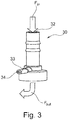
- One solution in accordance with the present invention is to use an outlet fitting 30 such as the one shown in Figure 3 .
- the outlet fitting 30 is attachable to an outlet of the fluid reservoir and has a central bore 32 through which fluid can flow in to the fitting (indicated by arrow Fin) and out (indicated by arrow Fout).
- the outlet fitting 30 additionally includes a branch 33 having a bore 34 in fluid communication with the central bore 32. Wires of the detection means may pass out of the inside of the reservoir into the fitting 30 through central bore 32 and out of the bore 34 of branch 33. The wires can then be sealed around the bore 34 of the branch 33 so that fluid can not exit the central bore 32 via the bore 34 of the branch 33.
- sealing is achieved using a small sleeve of heat shrinkable tubing that is partially filled with an epoxy resin that cures rapidly when heat is applied during shrinking of the sleeve.
- sealing is achieved by using wires that are sheathed in an elastomeric (e.g. rubber) tubing.
- the wires may be pre-moulded in the sheath, for example.
- the sheathed wires can then be inserted through the bore 34 of the branch 33 allowing the elastomeric nature of the sheath to provide a seal so that fluid cannot escape through the bore 34 of the branch 33.
- the pump 20 and strip 40 (complete with detection means) and outlet fitting 30 are provided in one assembled unit 60, as shown in Figure 5 .
- the assembled unit 60 can be inserted into an opening, such as the fluid outlet, of the fluid reservoir.
- the unit 60 may be treated as disposable or may be cleaned at regular intervals to maintain cleanliness.
Landscapes
- Health & Medical Sciences (AREA)
- Life Sciences & Earth Sciences (AREA)
- Engineering & Computer Science (AREA)
- Heart & Thoracic Surgery (AREA)
- Veterinary Medicine (AREA)
- General Health & Medical Sciences (AREA)
- Public Health (AREA)
- Animal Behavior & Ethology (AREA)
- Biomedical Technology (AREA)
- Vascular Medicine (AREA)
- Physics & Mathematics (AREA)
- Urology & Nephrology (AREA)
- Medical Informatics (AREA)
- Molecular Biology (AREA)
- Surgery (AREA)
- Biophysics (AREA)
- Pathology (AREA)
- Physiology (AREA)
- Orthopedic Medicine & Surgery (AREA)
- Nursing (AREA)
- Epidemiology (AREA)
- Anesthesiology (AREA)
- Hematology (AREA)
- Mechanical Engineering (AREA)
- General Engineering & Computer Science (AREA)
- General Physics & Mathematics (AREA)
- Fluid Mechanics (AREA)
- Signal Processing (AREA)
- External Artificial Organs (AREA)
- Sampling And Sample Adjustment (AREA)
- Loading And Unloading Of Fuel Tanks Or Ships (AREA)
- Structures Of Non-Positive Displacement Pumps (AREA)
- Infusion, Injection, And Reservoir Apparatuses (AREA)
- Orthopedics, Nursing, And Contraception (AREA)
- Measurement Of Levels Of Liquids Or Fluent Solid Materials (AREA)
Applications Claiming Priority (3)
| Application Number | Priority Date | Filing Date | Title |
|---|---|---|---|
| GB1119676.3A GB2496605A (en) | 2011-11-15 | 2011-11-15 | Pump for use with urine collection bag |
| EP12794454.4A EP2779965B1 (en) | 2011-11-15 | 2012-11-15 | Fluid collection and expulsion apparatus |
| PCT/GB2012/052835 WO2013072689A2 (en) | 2011-11-15 | 2012-11-15 | Fluid collection and expulsion apparatus |
Related Parent Applications (2)
| Application Number | Title | Priority Date | Filing Date |
|---|---|---|---|
| EP12794454.4A Division EP2779965B1 (en) | 2011-11-15 | 2012-11-15 | Fluid collection and expulsion apparatus |
| EP12794454.4A Division-Into EP2779965B1 (en) | 2011-11-15 | 2012-11-15 | Fluid collection and expulsion apparatus |
Publications (2)
| Publication Number | Publication Date |
|---|---|
| EP2987473A1 EP2987473A1 (en) | 2016-02-24 |
| EP2987473B1 true EP2987473B1 (en) | 2019-09-04 |
Family
ID=45444145
Family Applications (3)
| Application Number | Title | Priority Date | Filing Date |
|---|---|---|---|
| EP15185024.5A Not-in-force EP2987473B1 (en) | 2011-11-15 | 2012-11-15 | Fluid collection and expulsion apparatus |
| EP12794454.4A Not-in-force EP2779965B1 (en) | 2011-11-15 | 2012-11-15 | Fluid collection and expulsion apparatus |
| EP15185023.7A Active EP2985011B1 (en) | 2011-11-15 | 2012-11-15 | Fluid collection and expulsion apparatus |
Family Applications After (2)
| Application Number | Title | Priority Date | Filing Date |
|---|---|---|---|
| EP12794454.4A Not-in-force EP2779965B1 (en) | 2011-11-15 | 2012-11-15 | Fluid collection and expulsion apparatus |
| EP15185023.7A Active EP2985011B1 (en) | 2011-11-15 | 2012-11-15 | Fluid collection and expulsion apparatus |
Country Status (15)
| Country | Link |
|---|---|
| US (1) | US20140338764A1 (enExample) |
| EP (3) | EP2987473B1 (enExample) |
| JP (1) | JP2014534892A (enExample) |
| KR (1) | KR20140105755A (enExample) |
| CN (1) | CN104039279B (enExample) |
| AU (1) | AU2012338565B2 (enExample) |
| BR (1) | BR112014011756A2 (enExample) |
| CA (1) | CA2855569A1 (enExample) |
| DK (1) | DK2779965T3 (enExample) |
| ES (1) | ES2560233T3 (enExample) |
| GB (3) | GB2496605A (enExample) |
| IN (1) | IN2014CN04208A (enExample) |
| PT (1) | PT2779965E (enExample) |
| RU (1) | RU2014124169A (enExample) |
| WO (1) | WO2013072689A2 (enExample) |
Families Citing this family (6)
| Publication number | Priority date | Publication date | Assignee | Title |
|---|---|---|---|---|
| DE102013102083A1 (de) * | 2013-03-04 | 2014-09-04 | Andromeda Medizinische Systeme Gmbh | Druckmesssystem |
| US20170312403A1 (en) | 2016-04-27 | 2017-11-02 | Sarah Elizabeth Hagarty | Simple Closed Loop System for Direct Harvest and Transfer for High Volume Fat Grafting |
| WO2018204929A1 (en) * | 2017-05-05 | 2018-11-08 | Hagarty Sarah Elizabeth | A system for the harvest and transfer for high volume fat grafting using a centrifugal pump |
| KR101923954B1 (ko) * | 2018-01-25 | 2018-11-30 | 주식회사 유비콤테크놀로지 | 소비전력이 절감된 배터리형 초음파식 수도미터 |
| KR102433455B1 (ko) * | 2021-02-05 | 2022-08-19 | 양승현 | 소변 주머니 및 이를 이용한 원격지 소변 변화량 모니터링 시스템 |
| KR102766130B1 (ko) * | 2021-09-28 | 2025-02-12 | 린나이코리아 주식회사 | 스케일 제거장치를 구비하는 수위센서 |
Family Cites Families (26)
| Publication number | Priority date | Publication date | Assignee | Title |
|---|---|---|---|---|
| US4898518A (en) * | 1988-08-31 | 1990-02-06 | Minnesota Mining & Manufacturing Company | Shaft driven disposable centrifugal pump |
| US5135485A (en) * | 1991-02-25 | 1992-08-04 | Louis Cohen | Capacitance-type fluid level sensor for i.v. and catheter bags |
| EP0610638A1 (en) * | 1993-01-13 | 1994-08-17 | A.M.C. ADVANCED MEDICAL CONCEPTS Ltd. | An incontinence aid assembly |
| US5582604A (en) * | 1994-05-31 | 1996-12-10 | The Procter & Gamble Company | Disposable absorbent article having a pump and an inflatable component |
| US5586862A (en) * | 1995-06-15 | 1996-12-24 | Danner; Michael | Centrifugal pump having a slidable gate |
| US6074180A (en) * | 1996-05-03 | 2000-06-13 | Medquest Products, Inc. | Hybrid magnetically suspended and rotated centrifugal pumping apparatus and method |
| US5807313A (en) * | 1996-07-19 | 1998-09-15 | C. R. Bard, Inc. | Battery powered surgical irrigator |
| FI964551L (fi) * | 1996-11-13 | 1998-05-14 | Ahlstroem Pumput Oy | Keskipakopumppu |
| AU1794700A (en) * | 1998-12-22 | 2000-07-12 | Alcor Medical Instruments Ltd. | Method and device for monitoring fluid level |
| DK200000733A (da) * | 1999-05-05 | 2000-08-29 | Coloplast As | Urinopsamlingspose |
| JP2001112806A (ja) * | 1999-10-18 | 2001-04-24 | Niles Parts Co Ltd | 排泄物処理装置 |
| US6547530B2 (en) * | 2000-05-19 | 2003-04-15 | Ntn Corporation | Fluid pump apparatus |
| JP3576081B2 (ja) * | 2000-08-02 | 2004-10-13 | 太産工業株式会社 | 排水ポンプ |
| GB0130894D0 (en) | 2001-12-21 | 2002-02-06 | Wills Trevor | Fluid collection apparatus |
| US6706027B2 (en) * | 2002-02-26 | 2004-03-16 | Mark R. Harvie | Automatic bladder relief system |
| GB0424046D0 (en) * | 2004-10-29 | 2004-12-01 | Smith & Nephew | Apparatus |
| CN100582490C (zh) * | 2004-12-03 | 2010-01-20 | 清华大学 | 一种超小型离心泵叶轮 |
| CN100432439C (zh) * | 2005-01-20 | 2008-11-12 | 株式会社日立制作所 | 便携式真空泵 |
| TWI274105B (en) * | 2005-01-20 | 2007-02-21 | Hitachi Ltd | Portable vacuum pump and automatic urination treatment apparatus using thereof |
| US7739907B2 (en) * | 2006-11-29 | 2010-06-22 | Future Path Medical Llc | Container for physiological fluids |
| US7931630B2 (en) * | 2005-07-05 | 2011-04-26 | C. R. Bard, Inc. | Multi-functional and modular urine collection system |
| WO2008063160A2 (en) * | 2006-10-31 | 2008-05-29 | Vernon Robert D | Urine receptacle and apparatus for automated disposal of urine |
| CN200963221Y (zh) * | 2006-11-10 | 2007-10-24 | 刘霞 | 定量报警腰侧尿袋 |
| JP4976190B2 (ja) * | 2007-04-26 | 2012-07-18 | ユニ・チャーム株式会社 | 吸収性物品、吸収性物品システム及び介護システム |
| JP5358103B2 (ja) * | 2008-02-14 | 2013-12-04 | ユニ・チャーム株式会社 | 自動尿処理装置 |
| NO328037B1 (no) * | 2008-05-22 | 2009-11-23 | Knut Inge Bonvik | System for sanntids langtidsregulering og/eller sanntids spektroskopi av en avgitt urinmengde hos pasienter |
-
2011
- 2011-11-15 GB GB1119676.3A patent/GB2496605A/en not_active Withdrawn
- 2011-11-15 GB GB1314219.5A patent/GB2503822B/en not_active Expired - Fee Related
- 2011-11-15 GB GB1314223.7A patent/GB2503823B/en not_active Expired - Fee Related
-
2012
- 2012-11-15 DK DK12794454.4T patent/DK2779965T3/en active
- 2012-11-15 CA CA2855569A patent/CA2855569A1/en not_active Abandoned
- 2012-11-15 EP EP15185024.5A patent/EP2987473B1/en not_active Not-in-force
- 2012-11-15 JP JP2014541752A patent/JP2014534892A/ja active Pending
- 2012-11-15 ES ES12794454.4T patent/ES2560233T3/es active Active
- 2012-11-15 KR KR1020147016232A patent/KR20140105755A/ko not_active Withdrawn
- 2012-11-15 AU AU2012338565A patent/AU2012338565B2/en not_active Expired - Fee Related
- 2012-11-15 RU RU2014124169/14A patent/RU2014124169A/ru not_active Application Discontinuation
- 2012-11-15 BR BR112014011756A patent/BR112014011756A2/pt not_active IP Right Cessation
- 2012-11-15 PT PT127944544T patent/PT2779965E/pt unknown
- 2012-11-15 EP EP12794454.4A patent/EP2779965B1/en not_active Not-in-force
- 2012-11-15 WO PCT/GB2012/052835 patent/WO2013072689A2/en not_active Ceased
- 2012-11-15 CN CN201280066257.6A patent/CN104039279B/zh not_active Expired - Fee Related
- 2012-11-15 EP EP15185023.7A patent/EP2985011B1/en active Active
- 2012-11-15 US US14/358,113 patent/US20140338764A1/en not_active Abandoned
-
2014
- 2014-06-05 IN IN4208CHN2014 patent/IN2014CN04208A/en unknown
Non-Patent Citations (1)
| Title |
|---|
| None * |
Also Published As
Similar Documents
| Publication | Publication Date | Title |
|---|---|---|
| EP2987473B1 (en) | Fluid collection and expulsion apparatus | |
| US20240156633A1 (en) | Fluid collection systems sensing and notification and related methods | |
| US3661143A (en) | Medical apparatus for drainage, collection and monitoring of body fluids | |
| JP2019512672A (ja) | 自動尿採取器−分析器 | |
| EP2268341B1 (en) | Antegrade colonic instillation apparatus | |
| BR112014011659B1 (pt) | dispositivo e método para manipulação de produção de urina | |
| HK1196934B (en) | Fluid collection and expulsion apparatus | |
| NZ625698B2 (en) | Fluid collection and expulsion apparatus | |
| NZ717292B2 (en) | Fluid collection and expulsion apparatus | |
| NZ717294B2 (en) | Fluid collection and expulsion apparatus | |
| US11911548B2 (en) | Peritoneal dialysis system including manifold assembly and peristaltic pump | |
| CN208799240U (zh) | 流体实时监测装置及其监测系统 | |
| CN209996867U (zh) | 一种具有报警功能的脑室引流装置 | |
| CN113893393B (zh) | 肾内科用集尿装置 | |
| KR102737409B1 (ko) | 소변량 자동 측정 장치 | |
| KR20230162216A (ko) | 소변량 자동 측정 장치 | |
| CN110448317A (zh) | 流体实时监测装置及其监测系统 |
Legal Events
| Date | Code | Title | Description |
|---|---|---|---|
| PUAI | Public reference made under article 153(3) epc to a published international application that has entered the european phase |
Free format text: ORIGINAL CODE: 0009012 |
|
| AC | Divisional application: reference to earlier application |
Ref document number: 2779965 Country of ref document: EP Kind code of ref document: P |
|
| AK | Designated contracting states |
Kind code of ref document: A1 Designated state(s): AL AT BE BG CH CY CZ DE DK EE ES FI FR GB GR HR HU IE IS IT LI LT LU LV MC MK MT NL NO PL PT RO RS SE SI SK SM TR |
|
| 17P | Request for examination filed |
Effective date: 20160824 |
|
| RBV | Designated contracting states (corrected) |
Designated state(s): AL AT BE BG CH CY CZ DE DK EE ES FI FR GB GR HR HU IE IS IT LI LT LU LV MC MK MT NL NO PL PT RO RS SE SI SK SM TR |
|
| GRAP | Despatch of communication of intention to grant a patent |
Free format text: ORIGINAL CODE: EPIDOSNIGR1 |
|
| STAA | Information on the status of an ep patent application or granted ep patent |
Free format text: STATUS: GRANT OF PATENT IS INTENDED |
|
| RIC1 | Information provided on ipc code assigned before grant |
Ipc: A61B 5/20 20060101ALI20170830BHEP Ipc: A61F 5/44 20060101AFI20170830BHEP Ipc: A61M 1/00 20060101ALI20170830BHEP |
|
| INTG | Intention to grant announced |
Effective date: 20170929 |
|
| GRAS | Grant fee paid |
Free format text: ORIGINAL CODE: EPIDOSNIGR3 |
|
| GRAJ | Information related to disapproval of communication of intention to grant by the applicant or resumption of examination proceedings by the epo deleted |
Free format text: ORIGINAL CODE: EPIDOSDIGR1 |
|
| GRAL | Information related to payment of fee for publishing/printing deleted |
Free format text: ORIGINAL CODE: EPIDOSDIGR3 |
|
| STAA | Information on the status of an ep patent application or granted ep patent |
Free format text: STATUS: REQUEST FOR EXAMINATION WAS MADE |
|
| INTC | Intention to grant announced (deleted) | ||
| GRAP | Despatch of communication of intention to grant a patent |
Free format text: ORIGINAL CODE: EPIDOSNIGR1 |
|
| STAA | Information on the status of an ep patent application or granted ep patent |
Free format text: STATUS: GRANT OF PATENT IS INTENDED |
|
| INTG | Intention to grant announced |
Effective date: 20180726 |
|
| 19U | Interruption of proceedings before grant |
Effective date: 20170725 |
|
| 19W | Proceedings resumed before grant after interruption of proceedings |
Effective date: 20181001 |
|
| RAP1 | Party data changed (applicant data changed or rights of an application transferred) |
Owner name: MELIO MEDICAL LIMITED |
|
| GRAA | (expected) grant |
Free format text: ORIGINAL CODE: 0009210 |
|
| STAA | Information on the status of an ep patent application or granted ep patent |
Free format text: STATUS: THE PATENT HAS BEEN GRANTED |
|
| AC | Divisional application: reference to earlier application |
Ref document number: 2779965 Country of ref document: EP Kind code of ref document: P |
|
| AK | Designated contracting states |
Kind code of ref document: B1 Designated state(s): AL AT BE BG CH CY CZ DE DK EE ES FI FR GB GR HR HU IE IS IT LI LT LU LV MC MK MT NL NO PL PT RO RS SE SI SK SM TR |
|
| REG | Reference to a national code |
Ref country code: GB Ref legal event code: FG4D |
|
| REG | Reference to a national code |
Ref country code: CH Ref legal event code: EP |
|
| REG | Reference to a national code |
Ref country code: AT Ref legal event code: REF Ref document number: 1174312 Country of ref document: AT Kind code of ref document: T Effective date: 20190915 |
|
| REG | Reference to a national code |
Ref country code: DE Ref legal event code: R096 Ref document number: 602012063771 Country of ref document: DE |
|
| REG | Reference to a national code |
Ref country code: IE Ref legal event code: FG4D |
|
| REG | Reference to a national code |
Ref country code: NL Ref legal event code: MP Effective date: 20190904 |
|
| REG | Reference to a national code |
Ref country code: LT Ref legal event code: MG4D |
|
| PG25 | Lapsed in a contracting state [announced via postgrant information from national office to epo] |
Ref country code: FI Free format text: LAPSE BECAUSE OF FAILURE TO SUBMIT A TRANSLATION OF THE DESCRIPTION OR TO PAY THE FEE WITHIN THE PRESCRIBED TIME-LIMIT Effective date: 20190904 Ref country code: LT Free format text: LAPSE BECAUSE OF FAILURE TO SUBMIT A TRANSLATION OF THE DESCRIPTION OR TO PAY THE FEE WITHIN THE PRESCRIBED TIME-LIMIT Effective date: 20190904 Ref country code: BG Free format text: LAPSE BECAUSE OF FAILURE TO SUBMIT A TRANSLATION OF THE DESCRIPTION OR TO PAY THE FEE WITHIN THE PRESCRIBED TIME-LIMIT Effective date: 20191204 Ref country code: NO Free format text: LAPSE BECAUSE OF FAILURE TO SUBMIT A TRANSLATION OF THE DESCRIPTION OR TO PAY THE FEE WITHIN THE PRESCRIBED TIME-LIMIT Effective date: 20191204 Ref country code: SE Free format text: LAPSE BECAUSE OF FAILURE TO SUBMIT A TRANSLATION OF THE DESCRIPTION OR TO PAY THE FEE WITHIN THE PRESCRIBED TIME-LIMIT Effective date: 20190904 Ref country code: HR Free format text: LAPSE BECAUSE OF FAILURE TO SUBMIT A TRANSLATION OF THE DESCRIPTION OR TO PAY THE FEE WITHIN THE PRESCRIBED TIME-LIMIT Effective date: 20190904 |
|
| PG25 | Lapsed in a contracting state [announced via postgrant information from national office to epo] |
Ref country code: LV Free format text: LAPSE BECAUSE OF FAILURE TO SUBMIT A TRANSLATION OF THE DESCRIPTION OR TO PAY THE FEE WITHIN THE PRESCRIBED TIME-LIMIT Effective date: 20190904 Ref country code: GR Free format text: LAPSE BECAUSE OF FAILURE TO SUBMIT A TRANSLATION OF THE DESCRIPTION OR TO PAY THE FEE WITHIN THE PRESCRIBED TIME-LIMIT Effective date: 20191205 Ref country code: RS Free format text: LAPSE BECAUSE OF FAILURE TO SUBMIT A TRANSLATION OF THE DESCRIPTION OR TO PAY THE FEE WITHIN THE PRESCRIBED TIME-LIMIT Effective date: 20190904 Ref country code: AL Free format text: LAPSE BECAUSE OF FAILURE TO SUBMIT A TRANSLATION OF THE DESCRIPTION OR TO PAY THE FEE WITHIN THE PRESCRIBED TIME-LIMIT Effective date: 20190904 Ref country code: ES Free format text: LAPSE BECAUSE OF FAILURE TO SUBMIT A TRANSLATION OF THE DESCRIPTION OR TO PAY THE FEE WITHIN THE PRESCRIBED TIME-LIMIT Effective date: 20190904 |
|
| REG | Reference to a national code |
Ref country code: AT Ref legal event code: MK05 Ref document number: 1174312 Country of ref document: AT Kind code of ref document: T Effective date: 20190904 |
|
| PG25 | Lapsed in a contracting state [announced via postgrant information from national office to epo] |
Ref country code: AT Free format text: LAPSE BECAUSE OF FAILURE TO SUBMIT A TRANSLATION OF THE DESCRIPTION OR TO PAY THE FEE WITHIN THE PRESCRIBED TIME-LIMIT Effective date: 20190904 Ref country code: NL Free format text: LAPSE BECAUSE OF FAILURE TO SUBMIT A TRANSLATION OF THE DESCRIPTION OR TO PAY THE FEE WITHIN THE PRESCRIBED TIME-LIMIT Effective date: 20190904 Ref country code: PL Free format text: LAPSE BECAUSE OF FAILURE TO SUBMIT A TRANSLATION OF THE DESCRIPTION OR TO PAY THE FEE WITHIN THE PRESCRIBED TIME-LIMIT Effective date: 20190904 Ref country code: EE Free format text: LAPSE BECAUSE OF FAILURE TO SUBMIT A TRANSLATION OF THE DESCRIPTION OR TO PAY THE FEE WITHIN THE PRESCRIBED TIME-LIMIT Effective date: 20190904 Ref country code: IT Free format text: LAPSE BECAUSE OF FAILURE TO SUBMIT A TRANSLATION OF THE DESCRIPTION OR TO PAY THE FEE WITHIN THE PRESCRIBED TIME-LIMIT Effective date: 20190904 Ref country code: PT Free format text: LAPSE BECAUSE OF FAILURE TO SUBMIT A TRANSLATION OF THE DESCRIPTION OR TO PAY THE FEE WITHIN THE PRESCRIBED TIME-LIMIT Effective date: 20200106 Ref country code: RO Free format text: LAPSE BECAUSE OF FAILURE TO SUBMIT A TRANSLATION OF THE DESCRIPTION OR TO PAY THE FEE WITHIN THE PRESCRIBED TIME-LIMIT Effective date: 20190904 |
|
| PG25 | Lapsed in a contracting state [announced via postgrant information from national office to epo] |
Ref country code: SM Free format text: LAPSE BECAUSE OF FAILURE TO SUBMIT A TRANSLATION OF THE DESCRIPTION OR TO PAY THE FEE WITHIN THE PRESCRIBED TIME-LIMIT Effective date: 20190904 Ref country code: CZ Free format text: LAPSE BECAUSE OF FAILURE TO SUBMIT A TRANSLATION OF THE DESCRIPTION OR TO PAY THE FEE WITHIN THE PRESCRIBED TIME-LIMIT Effective date: 20190904 Ref country code: SK Free format text: LAPSE BECAUSE OF FAILURE TO SUBMIT A TRANSLATION OF THE DESCRIPTION OR TO PAY THE FEE WITHIN THE PRESCRIBED TIME-LIMIT Effective date: 20190904 Ref country code: IS Free format text: LAPSE BECAUSE OF FAILURE TO SUBMIT A TRANSLATION OF THE DESCRIPTION OR TO PAY THE FEE WITHIN THE PRESCRIBED TIME-LIMIT Effective date: 20200224 |
|
| REG | Reference to a national code |
Ref country code: DE Ref legal event code: R097 Ref document number: 602012063771 Country of ref document: DE |
|
| REG | Reference to a national code |
Ref country code: CH Ref legal event code: PL |
|
| PLBE | No opposition filed within time limit |
Free format text: ORIGINAL CODE: 0009261 |
|
| STAA | Information on the status of an ep patent application or granted ep patent |
Free format text: STATUS: NO OPPOSITION FILED WITHIN TIME LIMIT |
|
| PG2D | Information on lapse in contracting state deleted |
Ref country code: IS |
|
| PG25 | Lapsed in a contracting state [announced via postgrant information from national office to epo] |
Ref country code: CH Free format text: LAPSE BECAUSE OF NON-PAYMENT OF DUE FEES Effective date: 20191130 Ref country code: LI Free format text: LAPSE BECAUSE OF NON-PAYMENT OF DUE FEES Effective date: 20191130 Ref country code: LU Free format text: LAPSE BECAUSE OF NON-PAYMENT OF DUE FEES Effective date: 20191115 Ref country code: DK Free format text: LAPSE BECAUSE OF FAILURE TO SUBMIT A TRANSLATION OF THE DESCRIPTION OR TO PAY THE FEE WITHIN THE PRESCRIBED TIME-LIMIT Effective date: 20190904 Ref country code: MC Free format text: LAPSE BECAUSE OF FAILURE TO SUBMIT A TRANSLATION OF THE DESCRIPTION OR TO PAY THE FEE WITHIN THE PRESCRIBED TIME-LIMIT Effective date: 20190904 Ref country code: IS Free format text: LAPSE BECAUSE OF FAILURE TO SUBMIT A TRANSLATION OF THE DESCRIPTION OR TO PAY THE FEE WITHIN THE PRESCRIBED TIME-LIMIT Effective date: 20200105 |
|
| 26N | No opposition filed |
Effective date: 20200605 |
|
| REG | Reference to a national code |
Ref country code: BE Ref legal event code: MM Effective date: 20191130 |
|
| PG25 | Lapsed in a contracting state [announced via postgrant information from national office to epo] |
Ref country code: SI Free format text: LAPSE BECAUSE OF FAILURE TO SUBMIT A TRANSLATION OF THE DESCRIPTION OR TO PAY THE FEE WITHIN THE PRESCRIBED TIME-LIMIT Effective date: 20190904 |
|
| PG25 | Lapsed in a contracting state [announced via postgrant information from national office to epo] |
Ref country code: IE Free format text: LAPSE BECAUSE OF NON-PAYMENT OF DUE FEES Effective date: 20191115 |
|
| PG25 | Lapsed in a contracting state [announced via postgrant information from national office to epo] |
Ref country code: BE Free format text: LAPSE BECAUSE OF NON-PAYMENT OF DUE FEES Effective date: 20191130 |
|
| PG25 | Lapsed in a contracting state [announced via postgrant information from national office to epo] |
Ref country code: CY Free format text: LAPSE BECAUSE OF FAILURE TO SUBMIT A TRANSLATION OF THE DESCRIPTION OR TO PAY THE FEE WITHIN THE PRESCRIBED TIME-LIMIT Effective date: 20190904 |
|
| PG25 | Lapsed in a contracting state [announced via postgrant information from national office to epo] |
Ref country code: MT Free format text: LAPSE BECAUSE OF FAILURE TO SUBMIT A TRANSLATION OF THE DESCRIPTION OR TO PAY THE FEE WITHIN THE PRESCRIBED TIME-LIMIT Effective date: 20190904 Ref country code: HU Free format text: LAPSE BECAUSE OF FAILURE TO SUBMIT A TRANSLATION OF THE DESCRIPTION OR TO PAY THE FEE WITHIN THE PRESCRIBED TIME-LIMIT; INVALID AB INITIO Effective date: 20121115 |
|
| PGFP | Annual fee paid to national office [announced via postgrant information from national office to epo] |
Ref country code: DE Payment date: 20210531 Year of fee payment: 9 Ref country code: FR Payment date: 20210526 Year of fee payment: 9 |
|
| PGFP | Annual fee paid to national office [announced via postgrant information from national office to epo] |
Ref country code: GB Payment date: 20210527 Year of fee payment: 9 |
|
| PG25 | Lapsed in a contracting state [announced via postgrant information from national office to epo] |
Ref country code: TR Free format text: LAPSE BECAUSE OF FAILURE TO SUBMIT A TRANSLATION OF THE DESCRIPTION OR TO PAY THE FEE WITHIN THE PRESCRIBED TIME-LIMIT Effective date: 20190904 |
|
| REG | Reference to a national code |
Ref country code: DE Ref legal event code: R119 Ref document number: 602012063771 Country of ref document: DE |
|
| PG25 | Lapsed in a contracting state [announced via postgrant information from national office to epo] |
Ref country code: MK Free format text: LAPSE BECAUSE OF FAILURE TO SUBMIT A TRANSLATION OF THE DESCRIPTION OR TO PAY THE FEE WITHIN THE PRESCRIBED TIME-LIMIT Effective date: 20190904 |
|
| GBPC | Gb: european patent ceased through non-payment of renewal fee |
Effective date: 20211115 |
|
| PG25 | Lapsed in a contracting state [announced via postgrant information from national office to epo] |
Ref country code: GB Free format text: LAPSE BECAUSE OF NON-PAYMENT OF DUE FEES Effective date: 20211115 Ref country code: DE Free format text: LAPSE BECAUSE OF NON-PAYMENT OF DUE FEES Effective date: 20220601 |
|
| PG25 | Lapsed in a contracting state [announced via postgrant information from national office to epo] |
Ref country code: FR Free format text: LAPSE BECAUSE OF NON-PAYMENT OF DUE FEES Effective date: 20211130 |