EP2985904B1 - Procédé pour le diagnostic du décalage du résolveur d'une machine électrique - Google Patents
Procédé pour le diagnostic du décalage du résolveur d'une machine électrique Download PDFInfo
- Publication number
- EP2985904B1 EP2985904B1 EP15179948.3A EP15179948A EP2985904B1 EP 2985904 B1 EP2985904 B1 EP 2985904B1 EP 15179948 A EP15179948 A EP 15179948A EP 2985904 B1 EP2985904 B1 EP 2985904B1
- Authority
- EP
- European Patent Office
- Prior art keywords
- axis
- resolver
- current
- offset
- minimum reluctance
- Prior art date
- Legal status (The legal status is an assumption and is not a legal conclusion. Google has not performed a legal analysis and makes no representation as to the accuracy of the status listed.)
- Active
Links
- 238000000034 method Methods 0.000 title claims description 32
- 238000003745 diagnosis Methods 0.000 title claims description 7
- 230000005284 excitation Effects 0.000 claims description 32
- 230000001052 transient effect Effects 0.000 claims description 25
- 230000007547 defect Effects 0.000 claims description 8
- 238000002347 injection Methods 0.000 claims description 6
- 239000007924 injection Substances 0.000 claims description 6
- 238000004804 winding Methods 0.000 description 11
- 230000009466 transformation Effects 0.000 description 8
- 238000012795 verification Methods 0.000 description 4
- 230000006399 behavior Effects 0.000 description 3
- 230000006870 function Effects 0.000 description 3
- 230000004048 modification Effects 0.000 description 3
- 238000012986 modification Methods 0.000 description 3
- 238000010586 diagram Methods 0.000 description 2
- 239000011159 matrix material Substances 0.000 description 2
- 230000004044 response Effects 0.000 description 2
- 230000001133 acceleration Effects 0.000 description 1
- 230000000903 blocking effect Effects 0.000 description 1
- 238000006243 chemical reaction Methods 0.000 description 1
- 230000001419 dependent effect Effects 0.000 description 1
- 238000002405 diagnostic procedure Methods 0.000 description 1
- 230000000694 effects Effects 0.000 description 1
- 238000005516 engineering process Methods 0.000 description 1
- 230000014509 gene expression Effects 0.000 description 1
- 238000005259 measurement Methods 0.000 description 1
- 230000010363 phase shift Effects 0.000 description 1
- 238000012545 processing Methods 0.000 description 1
- 239000000243 solution Substances 0.000 description 1
- 239000007858 starting material Substances 0.000 description 1
- 238000000844 transformation Methods 0.000 description 1
- 230000007704 transition Effects 0.000 description 1
Images


Classifications
-
- B—PERFORMING OPERATIONS; TRANSPORTING
- B60—VEHICLES IN GENERAL
- B60L—PROPULSION OF ELECTRICALLY-PROPELLED VEHICLES; SUPPLYING ELECTRIC POWER FOR AUXILIARY EQUIPMENT OF ELECTRICALLY-PROPELLED VEHICLES; ELECTRODYNAMIC BRAKE SYSTEMS FOR VEHICLES IN GENERAL; MAGNETIC SUSPENSION OR LEVITATION FOR VEHICLES; MONITORING OPERATING VARIABLES OF ELECTRICALLY-PROPELLED VEHICLES; ELECTRIC SAFETY DEVICES FOR ELECTRICALLY-PROPELLED VEHICLES
- B60L15/00—Methods, circuits, or devices for controlling the traction-motor speed of electrically-propelled vehicles
- B60L15/02—Methods, circuits, or devices for controlling the traction-motor speed of electrically-propelled vehicles characterised by the form of the current used in the control circuit
- B60L15/025—Methods, circuits, or devices for controlling the traction-motor speed of electrically-propelled vehicles characterised by the form of the current used in the control circuit using field orientation; Vector control; Direct Torque Control [DTC]
-
- B—PERFORMING OPERATIONS; TRANSPORTING
- B60—VEHICLES IN GENERAL
- B60L—PROPULSION OF ELECTRICALLY-PROPELLED VEHICLES; SUPPLYING ELECTRIC POWER FOR AUXILIARY EQUIPMENT OF ELECTRICALLY-PROPELLED VEHICLES; ELECTRODYNAMIC BRAKE SYSTEMS FOR VEHICLES IN GENERAL; MAGNETIC SUSPENSION OR LEVITATION FOR VEHICLES; MONITORING OPERATING VARIABLES OF ELECTRICALLY-PROPELLED VEHICLES; ELECTRIC SAFETY DEVICES FOR ELECTRICALLY-PROPELLED VEHICLES
- B60L3/00—Electric devices on electrically-propelled vehicles for safety purposes; Monitoring operating variables, e.g. speed, deceleration or energy consumption
- B60L3/0023—Detecting, eliminating, remedying or compensating for drive train abnormalities, e.g. failures within the drive train
- B60L3/0038—Detecting, eliminating, remedying or compensating for drive train abnormalities, e.g. failures within the drive train relating to sensors
-
- B—PERFORMING OPERATIONS; TRANSPORTING
- B60—VEHICLES IN GENERAL
- B60L—PROPULSION OF ELECTRICALLY-PROPELLED VEHICLES; SUPPLYING ELECTRIC POWER FOR AUXILIARY EQUIPMENT OF ELECTRICALLY-PROPELLED VEHICLES; ELECTRODYNAMIC BRAKE SYSTEMS FOR VEHICLES IN GENERAL; MAGNETIC SUSPENSION OR LEVITATION FOR VEHICLES; MONITORING OPERATING VARIABLES OF ELECTRICALLY-PROPELLED VEHICLES; ELECTRIC SAFETY DEVICES FOR ELECTRICALLY-PROPELLED VEHICLES
- B60L3/00—Electric devices on electrically-propelled vehicles for safety purposes; Monitoring operating variables, e.g. speed, deceleration or energy consumption
- B60L3/0023—Detecting, eliminating, remedying or compensating for drive train abnormalities, e.g. failures within the drive train
- B60L3/0061—Detecting, eliminating, remedying or compensating for drive train abnormalities, e.g. failures within the drive train relating to electrical machines
-
- B—PERFORMING OPERATIONS; TRANSPORTING
- B60—VEHICLES IN GENERAL
- B60L—PROPULSION OF ELECTRICALLY-PROPELLED VEHICLES; SUPPLYING ELECTRIC POWER FOR AUXILIARY EQUIPMENT OF ELECTRICALLY-PROPELLED VEHICLES; ELECTRODYNAMIC BRAKE SYSTEMS FOR VEHICLES IN GENERAL; MAGNETIC SUSPENSION OR LEVITATION FOR VEHICLES; MONITORING OPERATING VARIABLES OF ELECTRICALLY-PROPELLED VEHICLES; ELECTRIC SAFETY DEVICES FOR ELECTRICALLY-PROPELLED VEHICLES
- B60L3/00—Electric devices on electrically-propelled vehicles for safety purposes; Monitoring operating variables, e.g. speed, deceleration or energy consumption
- B60L3/12—Recording operating variables ; Monitoring of operating variables
-
- G—PHYSICS
- G01—MEASURING; TESTING
- G01D—MEASURING NOT SPECIALLY ADAPTED FOR A SPECIFIC VARIABLE; ARRANGEMENTS FOR MEASURING TWO OR MORE VARIABLES NOT COVERED IN A SINGLE OTHER SUBCLASS; TARIFF METERING APPARATUS; MEASURING OR TESTING NOT OTHERWISE PROVIDED FOR
- G01D5/00—Mechanical means for transferring the output of a sensing member; Means for converting the output of a sensing member to another variable where the form or nature of the sensing member does not constrain the means for converting; Transducers not specially adapted for a specific variable
- G01D5/12—Mechanical means for transferring the output of a sensing member; Means for converting the output of a sensing member to another variable where the form or nature of the sensing member does not constrain the means for converting; Transducers not specially adapted for a specific variable using electric or magnetic means
- G01D5/14—Mechanical means for transferring the output of a sensing member; Means for converting the output of a sensing member to another variable where the form or nature of the sensing member does not constrain the means for converting; Transducers not specially adapted for a specific variable using electric or magnetic means influencing the magnitude of a current or voltage
- G01D5/20—Mechanical means for transferring the output of a sensing member; Means for converting the output of a sensing member to another variable where the form or nature of the sensing member does not constrain the means for converting; Transducers not specially adapted for a specific variable using electric or magnetic means influencing the magnitude of a current or voltage by varying inductance, e.g. by a movable armature
- G01D5/204—Mechanical means for transferring the output of a sensing member; Means for converting the output of a sensing member to another variable where the form or nature of the sensing member does not constrain the means for converting; Transducers not specially adapted for a specific variable using electric or magnetic means influencing the magnitude of a current or voltage by varying inductance, e.g. by a movable armature by influencing the mutual induction between two or more coils
- G01D5/2073—Mechanical means for transferring the output of a sensing member; Means for converting the output of a sensing member to another variable where the form or nature of the sensing member does not constrain the means for converting; Transducers not specially adapted for a specific variable using electric or magnetic means influencing the magnitude of a current or voltage by varying inductance, e.g. by a movable armature by influencing the mutual induction between two or more coils by movement of a single coil with respect to two or more coils
-
- G—PHYSICS
- G01—MEASURING; TESTING
- G01D—MEASURING NOT SPECIALLY ADAPTED FOR A SPECIFIC VARIABLE; ARRANGEMENTS FOR MEASURING TWO OR MORE VARIABLES NOT COVERED IN A SINGLE OTHER SUBCLASS; TARIFF METERING APPARATUS; MEASURING OR TESTING NOT OTHERWISE PROVIDED FOR
- G01D5/00—Mechanical means for transferring the output of a sensing member; Means for converting the output of a sensing member to another variable where the form or nature of the sensing member does not constrain the means for converting; Transducers not specially adapted for a specific variable
- G01D5/12—Mechanical means for transferring the output of a sensing member; Means for converting the output of a sensing member to another variable where the form or nature of the sensing member does not constrain the means for converting; Transducers not specially adapted for a specific variable using electric or magnetic means
- G01D5/244—Mechanical means for transferring the output of a sensing member; Means for converting the output of a sensing member to another variable where the form or nature of the sensing member does not constrain the means for converting; Transducers not specially adapted for a specific variable using electric or magnetic means influencing characteristics of pulses or pulse trains; generating pulses or pulse trains
- G01D5/24471—Error correction
- G01D5/2448—Correction of gain, threshold, offset or phase control
-
- H—ELECTRICITY
- H02—GENERATION; CONVERSION OR DISTRIBUTION OF ELECTRIC POWER
- H02K—DYNAMO-ELECTRIC MACHINES
- H02K11/00—Structural association of dynamo-electric machines with electric components or with devices for shielding, monitoring or protection
- H02K11/20—Structural association of dynamo-electric machines with electric components or with devices for shielding, monitoring or protection for measuring, monitoring, testing, protecting or switching
- H02K11/21—Devices for sensing speed or position, or actuated thereby
- H02K11/225—Detecting coils
-
- H—ELECTRICITY
- H02—GENERATION; CONVERSION OR DISTRIBUTION OF ELECTRIC POWER
- H02P—CONTROL OR REGULATION OF ELECTRIC MOTORS, ELECTRIC GENERATORS OR DYNAMO-ELECTRIC CONVERTERS; CONTROLLING TRANSFORMERS, REACTORS OR CHOKE COILS
- H02P21/00—Arrangements or methods for the control of electric machines by vector control, e.g. by control of field orientation
- H02P21/24—Vector control not involving the use of rotor position or rotor speed sensors
- H02P21/32—Determining the initial rotor position
-
- H—ELECTRICITY
- H02—GENERATION; CONVERSION OR DISTRIBUTION OF ELECTRIC POWER
- H02P—CONTROL OR REGULATION OF ELECTRIC MOTORS, ELECTRIC GENERATORS OR DYNAMO-ELECTRIC CONVERTERS; CONTROLLING TRANSFORMERS, REACTORS OR CHOKE COILS
- H02P6/00—Arrangements for controlling synchronous motors or other dynamo-electric motors using electronic commutation dependent on the rotor position; Electronic commutators therefor
- H02P6/14—Electronic commutators
- H02P6/16—Circuit arrangements for detecting position
- H02P6/18—Circuit arrangements for detecting position without separate position detecting elements
- H02P6/183—Circuit arrangements for detecting position without separate position detecting elements using an injected high frequency signal
-
- B—PERFORMING OPERATIONS; TRANSPORTING
- B60—VEHICLES IN GENERAL
- B60L—PROPULSION OF ELECTRICALLY-PROPELLED VEHICLES; SUPPLYING ELECTRIC POWER FOR AUXILIARY EQUIPMENT OF ELECTRICALLY-PROPELLED VEHICLES; ELECTRODYNAMIC BRAKE SYSTEMS FOR VEHICLES IN GENERAL; MAGNETIC SUSPENSION OR LEVITATION FOR VEHICLES; MONITORING OPERATING VARIABLES OF ELECTRICALLY-PROPELLED VEHICLES; ELECTRIC SAFETY DEVICES FOR ELECTRICALLY-PROPELLED VEHICLES
- B60L2220/00—Electrical machine types; Structures or applications thereof
- B60L2220/10—Electrical machine types
- B60L2220/14—Synchronous machines
-
- B—PERFORMING OPERATIONS; TRANSPORTING
- B60—VEHICLES IN GENERAL
- B60L—PROPULSION OF ELECTRICALLY-PROPELLED VEHICLES; SUPPLYING ELECTRIC POWER FOR AUXILIARY EQUIPMENT OF ELECTRICALLY-PROPELLED VEHICLES; ELECTRODYNAMIC BRAKE SYSTEMS FOR VEHICLES IN GENERAL; MAGNETIC SUSPENSION OR LEVITATION FOR VEHICLES; MONITORING OPERATING VARIABLES OF ELECTRICALLY-PROPELLED VEHICLES; ELECTRIC SAFETY DEVICES FOR ELECTRICALLY-PROPELLED VEHICLES
- B60L2220/00—Electrical machine types; Structures or applications thereof
- B60L2220/10—Electrical machine types
- B60L2220/16—DC brushless machines
-
- B—PERFORMING OPERATIONS; TRANSPORTING
- B60—VEHICLES IN GENERAL
- B60L—PROPULSION OF ELECTRICALLY-PROPELLED VEHICLES; SUPPLYING ELECTRIC POWER FOR AUXILIARY EQUIPMENT OF ELECTRICALLY-PROPELLED VEHICLES; ELECTRODYNAMIC BRAKE SYSTEMS FOR VEHICLES IN GENERAL; MAGNETIC SUSPENSION OR LEVITATION FOR VEHICLES; MONITORING OPERATING VARIABLES OF ELECTRICALLY-PROPELLED VEHICLES; ELECTRIC SAFETY DEVICES FOR ELECTRICALLY-PROPELLED VEHICLES
- B60L2240/00—Control parameters of input or output; Target parameters
- B60L2240/40—Drive Train control parameters
- B60L2240/42—Drive Train control parameters related to electric machines
- B60L2240/421—Speed
-
- B—PERFORMING OPERATIONS; TRANSPORTING
- B60—VEHICLES IN GENERAL
- B60L—PROPULSION OF ELECTRICALLY-PROPELLED VEHICLES; SUPPLYING ELECTRIC POWER FOR AUXILIARY EQUIPMENT OF ELECTRICALLY-PROPELLED VEHICLES; ELECTRODYNAMIC BRAKE SYSTEMS FOR VEHICLES IN GENERAL; MAGNETIC SUSPENSION OR LEVITATION FOR VEHICLES; MONITORING OPERATING VARIABLES OF ELECTRICALLY-PROPELLED VEHICLES; ELECTRIC SAFETY DEVICES FOR ELECTRICALLY-PROPELLED VEHICLES
- B60L2240/00—Control parameters of input or output; Target parameters
- B60L2240/40—Drive Train control parameters
- B60L2240/42—Drive Train control parameters related to electric machines
- B60L2240/427—Voltage
-
- B—PERFORMING OPERATIONS; TRANSPORTING
- B60—VEHICLES IN GENERAL
- B60L—PROPULSION OF ELECTRICALLY-PROPELLED VEHICLES; SUPPLYING ELECTRIC POWER FOR AUXILIARY EQUIPMENT OF ELECTRICALLY-PROPELLED VEHICLES; ELECTRODYNAMIC BRAKE SYSTEMS FOR VEHICLES IN GENERAL; MAGNETIC SUSPENSION OR LEVITATION FOR VEHICLES; MONITORING OPERATING VARIABLES OF ELECTRICALLY-PROPELLED VEHICLES; ELECTRIC SAFETY DEVICES FOR ELECTRICALLY-PROPELLED VEHICLES
- B60L2240/00—Control parameters of input or output; Target parameters
- B60L2240/40—Drive Train control parameters
- B60L2240/42—Drive Train control parameters related to electric machines
- B60L2240/429—Current
-
- H—ELECTRICITY
- H02—GENERATION; CONVERSION OR DISTRIBUTION OF ELECTRIC POWER
- H02P—CONTROL OR REGULATION OF ELECTRIC MOTORS, ELECTRIC GENERATORS OR DYNAMO-ELECTRIC CONVERTERS; CONTROLLING TRANSFORMERS, REACTORS OR CHOKE COILS
- H02P2203/00—Indexing scheme relating to controlling arrangements characterised by the means for detecting the position of the rotor
- H02P2203/11—Determination or estimation of the rotor position or other motor parameters based on the analysis of high frequency signals
-
- Y—GENERAL TAGGING OF NEW TECHNOLOGICAL DEVELOPMENTS; GENERAL TAGGING OF CROSS-SECTIONAL TECHNOLOGIES SPANNING OVER SEVERAL SECTIONS OF THE IPC; TECHNICAL SUBJECTS COVERED BY FORMER USPC CROSS-REFERENCE ART COLLECTIONS [XRACs] AND DIGESTS
- Y02—TECHNOLOGIES OR APPLICATIONS FOR MITIGATION OR ADAPTATION AGAINST CLIMATE CHANGE
- Y02T—CLIMATE CHANGE MITIGATION TECHNOLOGIES RELATED TO TRANSPORTATION
- Y02T10/00—Road transport of goods or passengers
- Y02T10/60—Other road transportation technologies with climate change mitigation effect
- Y02T10/64—Electric machine technologies in electromobility
Definitions
- the present invention relates in general to electric machines and, in particular, to a diagnostic methodology for the recognition of the mutual positioning of a rotor and a stator in an electric machine, specifically an electric motor without brushes (brushless) with internal magnets, such as for example a drive motor for a vehicle.
- the invention relates to a method for the diagnosis of the offset of the resolver of an electric machine according to the preamble of Claim 1.
- An electric machine such as an electric starter motor or a drive motor for an electric or hybrid vehicle, is conventionally equipped with a device for sensing the angular position or resolver, adapted to determine the mutual angular position between a rotary shaft and a stationary portion of the machine, which corresponds to the mutual angular position between a rotor and a stator.
- the information on angular position between rotor and stator is indispensible in the control of an electric motor, so that a unit for controlling the motor including an inverter circuit for generating the excitation currents of the motor is able to control the injection of current into the motor in the correct manner, controlling the rotation of the motor in the desired direction.
- the resolver is an analogue transducer of angular position, which comprises a mobile part, associated with the rotor or with the rotary shaft of the electric machine, and a fixed part, associated with the stator or with another stationary portion of the electric machine.
- the resolver comprises an excitation winding through which a sinusoidal excitation current flows (with an angular frequency ⁇ higher than the angular velocity), and two stationary windings (rigidly attached to the fixed part) in electrical phase quadrature.
- the excitation winding may be rigidly attached to the mobile part, or this may also be accommodated on the fixed part, if the mobile part has at least one pair of magnetic poles.
- the mobile part set in rotation induces in the fixed windings an e.m.f. composed of two components: a first component of transformer-type origin, due to the variations in an excitation voltage V r , and a second component due to the relative motion of the mobile part with respect to the fixed windings, which is proportional to the sine or to the cosine of the angle ⁇ identified by the position of the mobile part with respect to a predetermined reference.
- the sine and the cosine of the angular position of the mobile part modulate in amplitude the carrier with an angular frequency ⁇ present on the winding excitation. From the voltage signals V s1 and V s2 at ends of the fixed windings, by demodulation, it is possible to obtain an estimate of the angle ⁇ .
- the mobile part and the fixed part of the resolver are stably attached to the motor in a random, undetermined position or - as an alternative, if a controlled procedure for assembly of the resolver with respect to the stator of the motor is provided - in a position close to a nominal value, taking into account the assembly tolerances, whereby a difference is established between the reference position of the resolver and a reference position of minimum reluctance of the electric motor, commonly known as offset of the resolver.
- This position is measured at the end of the assembly line of an electric motor and is stored in memory within the control unit of the motor as the predetermined offset of the resolver.
- a method for calibrating the offset of the resolver is known from US 2014/015457 .
- control unit In normal operation of the electric motor, the control unit is capable of determining the correct angular position of the motor (the mutual angular position between stator and rotor) based on the output signal of the resolver knowing the offset of the resolver.
- anomalies During the normal operation of an electric motor, it is possible for anomalies to occur, for example on the rotor, in such a manner as to modify the offset of the resolver with respect to the predetermined one imposed at the production site.
- control unit of the motor does not recognize a modification of the offset of the resolver, the latter is no longer capable of determining the correct angular position of the motor or the position of minimum reluctance of the motor, which causes a lower torque to be provided or creates even serious drawbacks, such as unexpected behaviours in acceleration and deceleration when the vehicle is being driven, and - as a result of the erroneous control of the motor - the rupture of the rotor which determines the blocking of the motor drive shaft or the rupture of the pinion.
- the erroneous interpretation of the position of the rotor by the control unit may cause the inversion of the sign of the torque applied to the drive shaft with respect to that requested, causing the movement of the vehicle in the opposite direction to that desired, with consequent serious risks for the people on board the vehicle or around it.
- the aim of the present invention is thus to provide a satisfactory solution to the aforementioned problems, while avoiding the drawbacks of the known technology.
- the aim of the present invention is to provide a method that may be implemented on board an electric motor for recognizing a modification of the offset of the resolver, for example a modification of the offset of the resolver caused accidentally, i.e. for recognizing if the actual offset of the resolver corresponds to the predetermined offset of the resolver.
- the present invention is based on the principle of diagnosing the offset of the resolver of an electric machine, known a priori since determined at the production site, with the purpose of determining the correctness of information on angular position of the electric machine, i.e. of verifying the validity of the predetermined offset of the resolver, i.e. the correspondence between the predetermined offset of the resolver and the actual offset of the resolver.
- Diagnosis of the offset of the resolver of an electric machine means verification of the correct phasing between an angular position of the resolver and the mutual angular position between rotor and stator of the electric machine.
- the correctness of the assumed offset i.e. the correspondence of the actual offset of the resolver with the predetermined offset of the resolver, is verified by exciting the motor in pulsed mode in a preset configuration of assumed minimum reluctance determined as a function of the offset of the resolver known a priori, and in preset positions angularly displaced with respect to the position of assumed minimum reluctance by a calibratable value.
- the position of minimum reluctance of an electric machine is a known position (acquired from the resolver having a knowledge of the predetermined offset of the resolver) obtained from the phase-shift between the magnetic axis of the stator phases (typically that associated with the phase a) and the rotor axis coinciding with the magnetic path that more is opposed to the magnetic field lines.
- the configuration of minimum reluctance is a configuration for which voltages applied to the phases of an electric machine exclusively determine the excitation of a current on an axis aligned to a phase of the machine, whereby an electromagnetic drive torque is not generated.
- the reference system ABC is first of all convertible into a stationary reference system d-q (shown in the figure with apex s) in which the axes are located in a fixed reference, via the conversion matrix
- (where the current i c - i a - i b )
- the method for the diagnosis of the offset of the resolver of an electric motor that forms the subject of the present invention is carried out with the motor not in motion via the application of voltage pulses to the phases of the motor, having a sinusoidal waveform at a preset frequency, for example in the range between 400Hz and 1.2kHz, and preferably around 800Hz, in such a manner as to determine the injection of pulses of an exploring excitation current on an axis of minimum reluctance of the system (axis d) and evaluating the effects that these have on the current that is established on the axis of minimum reluctance (axis d) and on the axis in quadrature to it (axis q).
- a preset frequency for example in the range between 400Hz and 1.2kHz, and preferably around 800Hz
- the injection of the exploring current on the axis d of the system happens, without generating torque, by establishing voltages or injecting current onto the phases according to the aforementioned equations of the Park transforms.
- the current on the axis of minimum reluctance and on the axis in quadrature is determined by reading the currents on the phases of the motor and interpreted according to the aforementioned equations.
- the strategy for verifying the offset of the resolver comprises two phases.
- the injection of an exploring excitation current only on the axis d of the system corresponds to a current of maximum value, and proportional to the intensity of the injected exploring current, on this axis and to a current on the axis in quadrature theoretically zero.
- the exploring excitation current is injected into a non-correct reference system, but phase-shifted by an angle equal to the offset from the configuration of minimum reluctance.
- This offset corresponds to the errore on the offset of the resolver, i.e. to a condition where the predetermined offset of the resolver does not correspond to the actual offset of the resolver.
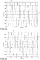
- a current on the axis d is obtained with a value less than the preceding value, and a current on the axis q with a value higher than that obtained by applying the exploring excitation current to the motor in the configuration of minimum reluctance.
- One further piece of information on the correctness of the offset of the resolver may be obtained by evaluating the phase of the currents d-q.
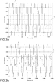
- Figures 3a, 3b , 3c show the possible conditions in the case of a correct offset of the resolver.
- the currents d-q are in phase opposition to each other ( figure 3b ), while in the case in which the reference system for application of the exploring excitation current is translated short of a value predetermined and calibratable with respect to the position of minimum reluctance, the currents d-q are in phase ( figure 3c ).
- the electric motor is indicated by 10, operationally controlled by a modulation module 12 of an inverter circuit, which receives at the input from a control module PI 14 voltage commands at each phase for the actuation of the motor, and from a block 16 for verification of the offset of the resolver, the control signals for an exploring current for each phase, indicated S A , S B , S C .
- These signals are produced from a current modulator 20 through a reference system transformation module 22.
- the block 16 for verification of the offset of the resolver furthermore comprises a processing module 30 for diagnosing the position of the rotor to whose input a module for calculating the mean 32 is coupled, which is disposed downstream of a reference system transformation module 34 coupled to the output of the electric motor.
- the method is implemented by the system in the figure as follows.
- the method is carried out with the motor not in motion, whereby the commands for actuation of the motor, generated by the control module PI 14, are temporarily inhibited or else the phase voltages for each phase are set to zero.
- a sinusoidal voltage waveform generated by the current modulator 20 is transformed from the rotating two-phase reference system d-q to the three-phase system A,B,C via the module 22 and supplied to the motor as a set of three control signals for an exploring excitation current for each phase, indicated S A , S B , S C , with an angle predetermined as a function of the phase of the strategy.
- the same offset angle of the resolver is used as is used in the normal operation of the vehicle.
- an angle is used whose value is varied with respect to the offset angle of the resolver by a predetermined and calibratable amount, preferably not greater than 20°, in such a manner as to evaluate the response of the motor in a different reference system.
- the diagnostic method subject of the invention is thus executed in a first transient (following a first pulse of exploring excitation current) considering the position of the rotor read by the resolver, in a second transient (following a second pulse of exploring excitation current) considering the position of the rotor read by the resolver phase-shifted by a predetermined extra angle, in a third transient (following a third pulse of exploring excitation current) considering the position of the rotor read by the resolver phase-shifted by a reduced predetermined angle.
- the current measured on the windings of the electric machine is transformed from the three-phase reference system A,B,C to the rotating two-phase reference system d-q in the module 34.
- a moving average is applied that is useful for obtaining a constant indicator that can be more easily analyzed for the transient in question, typically of 100ms duration for each of the three measurement transients.
- the moving average is carried out via an average of the values that each current assumes within a preset period corresponding to the transient or to its own internal interval.
- This procedure allows to evaluate which currents d-q the system applies with the position of the rotor used by the vehicle, and subsequently to assess whether this is the correct position (thus with minimum reluctance) by varying the reference system in which the exploring excitation current is applied.
- a second control is furthermore executed based on the phase of the currents d-q.
- the method subject of the invention is exclusively implemented when the motor is stationary, for example, in a currently preferred embodiment, before each start to movement of the electric motor, for example for a period of time of the order of 300ms, which is imperceptible by a user, such as the driver of a vehicle equipped with the aforementioned electric motor.
- the method subject of the present invention may, conveniently, be implemented in any other similar condition of stationary or stopped vehicle for which there is zero torque demand, for example when the vehicle is parked or stopped at traffic lights.
- the method subject of the invention is carried out without imposing a movement on the rotor of the electric machine, whereby it may also be implemented in vehicles in which electric drive motors are applied directly to the wheels of the vehicle, without causing an undesirable movement of these.
Claims (10)
- Procédé pour un diagnostic d'un décalage d'un résolveur d'une machine électrique (10), comprenant :l'acquisition d'un décalage prédéterminé d'un résolveur associé à ladite machine électrique (10) ;dans un premier état transitoire, la fourniture d'un courant d'excitation aux phases de ladite machine électrique (10) de manière à déterminer l'injection d'un courant d'excitation d'exploration sur un axe de réluctance minimale (d) de la machine électrique (10) dans un système de référence à deux phases rotatif (d-q) associé à un rotor de ladite machine électrique (10), dans lequel la position dudit axe de réluctance minimale (d) est déterminée en fonction dudit décalage prédéterminé du résolveur ;en conséquence dudit courant d'excitation, la détermination d'un courant (D) établi sur l'axe de réluctance minimale (d) et d'un courant (Q) établi sur un axe en quadrature de phase (q) par rapport à l'axe de réluctance minimale, en fonction du courant détecté sur les phases de ladite machine électrique (10) ;caractérisé en ce qu'il comprend en outre :dans des deuxième et troisième états transitoires, respectivement, la fourniture d'un courant d'excitation aux phases de ladite machine électrique (10) de manière à déterminer l'injection d'un courant d'excitation d'exploration sur ledit axe de réluctance minimale (d) de la machine électrique (10), dans lequel la position dudit axe de réluctance minimale (d) est déterminée en fonction d'un décalage modifié du résolveur, ledit décalage du résolveur étant modifié d'une quantité de déviation prédéterminée, en plus, respectivement en moins par rapport au décalage prédéterminé du résolveur ;le diagnostic de la correspondance d'un décalage réel du résolveur avec le décalage prédéterminé du résolveur si le courant (D) établi sur l'axe de réluctance minimale (d) dans le premier état transitoire est supérieur au courant (D) établi sur l'axe de réluctance minimale (d) dans le deuxième ou troisième état transitoire, ou si le courant (Q) établi sur l'axe en quadrature de phase (q) par rapport à l'axe de réluctance minimale dans le premier état transitoire est inférieur au courant (Q) établi sur l'axe en quadrature de phase (q) par rapport à l'axe de réluctance minimale dans le deuxième ou troisième état transitoire, oule diagnostic d'une erreur dans le décalage prédéterminé du résolveur si le courant (D) établi sur l'axe de réluctance minimale (d) dans le premier état transitoire est inférieur au courant (D) établi sur l'axe de réluctance minimale (d) dans le deuxième ou troisième état transitoire, ou si le courant (Q) établi sur l'axe en quadrature de phase (q) par rapport à l'axe de réluctance minimale dans le premier état transitoire est supérieur au courant (Q) établi sur l'axe en quadrature de phase (q) par rapport à l'axe de réluctance minimale dans le deuxième ou troisième état transitoire.
- Procédé selon la revendication 1, comprenant en outre les étapes de procédé supplémentaires de
diagnostic de la correspondance du décalage réel du résolveur avec le décalage prédéterminé du résolveur si le courant (D) établi sur l'axe de réluctance minimale (d) et le courant (Q) établi sur l'axe en quadrature de phase (q) par rapport à l'axe de réluctance minimale dans le deuxième état transitoire sont en opposition de phase lorsqu'un courant d'excitation d'exploration est injecté sur un axe de réluctance minimale déterminé en fonction d'un décalage du résolveur modifié d'une quantité de déviation prédéterminée en plus sur le décalage prédéterminé du résolveur, ou si le courant (D) établi sur l'axe de réluctance minimale (d) et le courant (Q) établi sur l'axe en quadrature de phase (q) par rapport à l'axe de réluctance minimale dans le troisième état transitoire sont en phase lorsqu'un courant d'excitation d'exploration est injecté sur un axe de réluctance minimale déterminé en fonction d'un décalage du résolveur modifié d'une quantité de déviation prédéterminée en moins par rapport au décalage prédéterminé du résolveur. - Procédé selon la revendication 1 ou 2, comprenant en outre l'étape supplémentaire de diagnostic d'une erreur dans le décalage prédéterminé du résolveur si le courant (D) établi sur l'axe de réluctance minimale (d) et le courant (Q) établi sur l'axe en quadrature de phase (q) par rapport à l'axe de réluctance minimale dans le deuxième état transitoire et dans le troisième état transitoire sont tous deux en phase ou en opposition de phase lorsqu'un courant d'excitation d'exploration est injecté sur un axe de réluctance minimale déterminé en fonction d'un décalage du résolveur modifié d'une quantité de déviation prédéterminée en plus ou en moins par rapport au décalage prédéterminé du résolveur.
- Procédé selon la revendication 2 ou 3, dans lequel ladite quantité de déviation prédéterminée du décalage n'est pas supérieure à 20°.
- Procédé selon l'une quelconque des revendications précédentes, dans lequel ledit courant d'excitation vers les phases de la machine électrique (10) est obtenu par l'application d'au moins une impulsion de tension (SA, SB, SC) qui ne génère aucun couple vers la machine électrique (10).
- Procédé selon la revendication 5, dans lequel ladite au moins une impulsion de tension (SA, SB, SC) présente une forme d'onde sinusoïdale à une fréquence prédéterminée.
- Procédé selon la revendication 6, dans lequel ladite fréquence prédéterminée est comprise entre 400 Hz et 1,2 kHz, et est de préférence de l'ordre de 800 Hz.
- Procédé selon l'une quelconque des revendications précédentes, comprenant le calcul (32) d'une moyenne des valeurs des courants établis sur l'axe de réluctance minimale (d) et sur un axe en quadrature de phase (q) par rapport à l'axe de réluctance minimale en conséquence dudit courant d'excitation, dans une période spécifique.
- Procédé selon l'une quelconque des revendications précédentes, caractérisé en ce qu'il est mis en oeuvre lorsque la machine électrique (10) ne se déplace pas.
- Procédé selon la revendication 9, caractérisé en ce qu'il est réalisé avant chaque début de mouvement de la machine électrique (10).
Applications Claiming Priority (1)
| Application Number | Priority Date | Filing Date | Title |
|---|---|---|---|
| ITTO20140654 | 2014-08-11 |
Publications (2)
| Publication Number | Publication Date |
|---|---|
| EP2985904A1 EP2985904A1 (fr) | 2016-02-17 |
| EP2985904B1 true EP2985904B1 (fr) | 2018-12-05 |
Family
ID=51703329
Family Applications (1)
| Application Number | Title | Priority Date | Filing Date |
|---|---|---|---|
| EP15179948.3A Active EP2985904B1 (fr) | 2014-08-11 | 2015-08-06 | Procédé pour le diagnostic du décalage du résolveur d'une machine électrique |
Country Status (4)
| Country | Link |
|---|---|
| US (1) | US9821679B2 (fr) |
| EP (1) | EP2985904B1 (fr) |
| JP (1) | JP6404190B2 (fr) |
| CN (1) | CN105375846B (fr) |
Cited By (1)
| Publication number | Priority date | Publication date | Assignee | Title |
|---|---|---|---|---|
| WO2023208272A1 (fr) * | 2022-04-28 | 2023-11-02 | Schaeffler Technologies AG & Co. KG | Procédé de détermination d'une position initiale de rotor d'un rotor, produit-programme informatique, unité de commande, machine électrique, procédé d'inspection et/ou d'essai et banc d'essai |
Families Citing this family (8)
| Publication number | Priority date | Publication date | Assignee | Title |
|---|---|---|---|---|
| CN109639209A (zh) * | 2017-10-09 | 2019-04-16 | 郑州宇通客车股份有限公司 | 一种电动汽车电机电角度调节方法及其装置 |
| KR102383373B1 (ko) * | 2017-11-21 | 2022-04-05 | 현대자동차주식회사 | 친환경 차량의 레졸버 옵셋 보정 장치 및 방법 |
| CN109327173A (zh) * | 2018-11-14 | 2019-02-12 | 苏州绿控传动科技股份有限公司 | 一种永磁同步电机旋转变压器零位自动识别方法 |
| DE102019111146A1 (de) * | 2019-04-30 | 2020-11-05 | Valeo Siemens Eautomotive Germany Gmbh | Verfahren zum Bestimmen eines Offsets eines Winkellagegebers an einer Rotorwelle einer elektrischen Maschine |
| KR102219185B1 (ko) * | 2019-11-29 | 2021-02-23 | 주식회사 브이씨텍 | 전기 자동차 제어 유닛의 실시간 전류 옵셋 보정 방법 |
| KR102403505B1 (ko) * | 2020-01-31 | 2022-05-27 | 국민대학교산학협력단 | 무부하 환경에서 영구자석 동기 전동기의 회전자의 초기 위치를 검출하는 방법 및 장치 |
| CN115189613A (zh) * | 2021-04-07 | 2022-10-14 | 日本电产艾莱希斯株式会社 | 电动机装置及车辆 |
| CN113271043B (zh) * | 2021-05-26 | 2022-12-23 | 永大电梯设备(中国)有限公司 | 旋转变压器转子同永磁同步电机转子角度偏差校正方法 |
Family Cites Families (18)
| Publication number | Priority date | Publication date | Assignee | Title |
|---|---|---|---|---|
| JP3675192B2 (ja) * | 1998-09-28 | 2005-07-27 | 株式会社日立製作所 | モータ制御装置および電気車用制御装置およびハイブリッド車用制御装置 |
| JP3789895B2 (ja) * | 2003-02-28 | 2006-06-28 | 三菱電機株式会社 | 巻線界磁型同期モータの制御装置および巻線界磁型同期モータの回転位置ずれ補正方法 |
| JP2005143256A (ja) * | 2003-11-10 | 2005-06-02 | Matsushita Electric Ind Co Ltd | モータ制御装置 |
| US7511448B2 (en) * | 2004-01-07 | 2009-03-31 | Mitsubishi Electric Corporation | Motor control device |
| DE102006028331B4 (de) * | 2005-06-27 | 2019-02-14 | Denso Corporation | Motorsteuervorrichtung |
| JP5055836B2 (ja) * | 2006-05-25 | 2012-10-24 | 日産自動車株式会社 | 同期モーター用磁極位置センサーの位相ズレ検出装置および検出方法 |
| DE102006025906A1 (de) * | 2006-06-02 | 2007-12-06 | Robert Bosch Gmbh | Verfahren zur Erkennung der Sensorzuordnung innerhalb einer elektrischen Maschine |
| US8018187B2 (en) * | 2009-01-05 | 2011-09-13 | GM Global Technology Operations LLC | Initial polarity detection for permanent magnet motor drives |
| WO2010137133A1 (fr) * | 2009-05-27 | 2010-12-02 | 三菱電機株式会社 | Dispositif d'estimation de position de pôle magnétique dans un moteur synchrone |
| GB201004049D0 (en) * | 2010-03-11 | 2010-04-28 | Trw Ltd | Electric motor control |
| FR2960358B1 (fr) * | 2010-05-21 | 2012-06-29 | Michelin Soc Tech | Installation et procede de mesure de decalage de l'angle d'un resolveur dans une machine electrique synchrone |
| FR2960357B1 (fr) * | 2010-05-21 | 2012-06-29 | Soc Tech Michelin | Procede de reglage automatique d'un resolveur d'une machine electrique |
| JP2010220472A (ja) * | 2010-05-31 | 2010-09-30 | Hitachi Automotive Systems Ltd | 同期モータ駆動装置 |
| JP5174205B2 (ja) * | 2011-04-01 | 2013-04-03 | ファナック株式会社 | 同期モータの磁極位置を検出する検出装置およびこれを備える制御装置 |
| CN103151982B (zh) * | 2011-12-07 | 2016-08-10 | 上海大郡动力控制技术有限公司 | 永磁电机旋转变压器检测零位补偿的自适应方法 |
| FR2990088B1 (fr) * | 2012-04-30 | 2014-05-09 | Renault Sa | Procede de determination du decalage angulaire entre le rotor et le stator d'une machine electrique d'un vehicule automobile |
| KR101382286B1 (ko) * | 2012-07-12 | 2014-04-08 | 기아자동차(주) | 차량 모터 위치센서의 옵셋 보정방법 |
| WO2014031166A1 (fr) * | 2012-08-21 | 2014-02-27 | Allison Transmission, Inc. | Système et procédé de correction d'erreurs dans des capteurs de position angulaire |
-
2015
- 2015-08-06 EP EP15179948.3A patent/EP2985904B1/fr active Active
- 2015-08-10 JP JP2015158296A patent/JP6404190B2/ja active Active
- 2015-08-11 US US14/823,601 patent/US9821679B2/en active Active
- 2015-08-11 CN CN201510490912.6A patent/CN105375846B/zh active Active
Non-Patent Citations (1)
| Title |
|---|
| None * |
Cited By (1)
| Publication number | Priority date | Publication date | Assignee | Title |
|---|---|---|---|---|
| WO2023208272A1 (fr) * | 2022-04-28 | 2023-11-02 | Schaeffler Technologies AG & Co. KG | Procédé de détermination d'une position initiale de rotor d'un rotor, produit-programme informatique, unité de commande, machine électrique, procédé d'inspection et/ou d'essai et banc d'essai |
Also Published As
| Publication number | Publication date |
|---|---|
| JP6404190B2 (ja) | 2018-10-10 |
| CN105375846A (zh) | 2016-03-02 |
| CN105375846B (zh) | 2019-10-11 |
| US20160043614A1 (en) | 2016-02-11 |
| US9821679B2 (en) | 2017-11-21 |
| EP2985904A1 (fr) | 2016-02-17 |
| JP2016038390A (ja) | 2016-03-22 |
Similar Documents
| Publication | Publication Date | Title |
|---|---|---|
| EP2985904B1 (fr) | Procédé pour le diagnostic du décalage du résolveur d'une machine électrique | |
| KR102034772B1 (ko) | 자동차의 전기 기계의 회전자와 고정자 사이의 각도 오프셋을 결정하는 방법 | |
| US8185342B2 (en) | Estimating rotor angular position and velocity and verifying accuracy of position sensor outputs | |
| EP2754998B1 (fr) | Dispositif d'acquisition de composante de fréquence d'erreur, dispositif d'acquisition d'angle de rotation, dispositif de commande de moteur et procédé d'acquisition d'angle de rotation | |
| JP5124483B2 (ja) | 同期機を駆動するための方法および装置 | |
| EP3026449B1 (fr) | Système et procédé de détection de pannes de moteur électrique | |
| EP1841056A1 (fr) | Contrôleur de moteur | |
| US10992245B2 (en) | Position estimation of permanent magnet synchronous machines through vibration induced saliency | |
| EP2930843B1 (fr) | Diagnostic de mesure de courant de phase | |
| JP5267843B2 (ja) | 電動パワーステアリング装置 | |
| KR101876064B1 (ko) | 영구자석 모터의 착자 불량 진단 방법 | |
| US20180054147A1 (en) | Method and system for sensorless determination of the orientation of the rotor of an ironless pmsm motor | |
| US6825646B2 (en) | Method for determining the position of the rotor of a synchronous alternating-current permanent-magnet machine | |
| US9441943B2 (en) | Method of determining the position and the speed of a rotor in a synchronous electric machine using state observers | |
| JP3707528B2 (ja) | 交流電動機の制御方法およびその制御装置 | |
| EP3273594A1 (fr) | Correction de signal de capteur de position de rotor | |
| US9184682B2 (en) | Control of a permanent-magnet electric machine | |
| EP1806835B1 (fr) | Appareil d excitation de moteur | |
| US20150214871A1 (en) | Method and System for Determining Motor Shaft Position | |
| EP2822175A1 (fr) | Dispositif de commande d'un moteur et procédé de commande associé | |
| US8922200B2 (en) | Method and device for determining a current angular position of a rotatable magnetic component in an electric drive | |
| EP3477846B1 (fr) | Procédé pour déterminer un décalage de mesure d'un capteur de position de rotor, unité de commande pour une machine électrique et machine électrique pour un véhicule | |
| JP2008086076A (ja) | 永久磁石同期電動機の制御装置 | |
| JP2009261102A (ja) | モータ制御装置 | |
| KR20200004634A (ko) | 차량용 모터 제어 장치 |
Legal Events
| Date | Code | Title | Description |
|---|---|---|---|
| PUAI | Public reference made under article 153(3) epc to a published international application that has entered the european phase |
Free format text: ORIGINAL CODE: 0009012 |
|
| AK | Designated contracting states |
Kind code of ref document: A1 Designated state(s): AL AT BE BG CH CY CZ DE DK EE ES FI FR GB GR HR HU IE IS IT LI LT LU LV MC MK MT NL NO PL PT RO RS SE SI SK SM TR |
|
| AX | Request for extension of the european patent |
Extension state: BA ME |
|
| 17P | Request for examination filed |
Effective date: 20160805 |
|
| RBV | Designated contracting states (corrected) |
Designated state(s): AL AT BE BG CH CY CZ DE DK EE ES FI FR GB GR HR HU IE IS IT LI LT LU LV MC MK MT NL NO PL PT RO RS SE SI SK SM TR |
|
| GRAP | Despatch of communication of intention to grant a patent |
Free format text: ORIGINAL CODE: EPIDOSNIGR1 |
|
| STAA | Information on the status of an ep patent application or granted ep patent |
Free format text: STATUS: GRANT OF PATENT IS INTENDED |
|
| RIC1 | Information provided on ipc code assigned before grant |
Ipc: H02P 21/32 20160101ALI20180524BHEP Ipc: G01D 5/244 20060101ALI20180524BHEP Ipc: B60L 3/00 20060101ALI20180524BHEP Ipc: B60L 15/02 20060101ALI20180524BHEP Ipc: B60L 3/12 20060101ALI20180524BHEP Ipc: H02P 6/18 20160101AFI20180524BHEP Ipc: G01D 5/20 20060101ALI20180524BHEP |
|
| INTG | Intention to grant announced |
Effective date: 20180619 |
|
| GRAS | Grant fee paid |
Free format text: ORIGINAL CODE: EPIDOSNIGR3 |
|
| GRAA | (expected) grant |
Free format text: ORIGINAL CODE: 0009210 |
|
| GRAA | (expected) grant |
Free format text: ORIGINAL CODE: 0009210 |
|
| STAA | Information on the status of an ep patent application or granted ep patent |
Free format text: STATUS: THE PATENT HAS BEEN GRANTED |
|
| AK | Designated contracting states |
Kind code of ref document: B1 Designated state(s): AL AT BE BG CH CY CZ DE DK EE ES FI FR GB GR HR HU IE IS IT LI LT LU LV MC MK MT NL NO PL PT RO RS SE SI SK SM TR |
|
| REG | Reference to a national code |
Ref country code: GB Ref legal event code: FG4D |
|
| REG | Reference to a national code |
Ref country code: CH Ref legal event code: EP |
|
| REG | Reference to a national code |
Ref country code: AT Ref legal event code: REF Ref document number: 1074318 Country of ref document: AT Kind code of ref document: T Effective date: 20181215 |
|
| REG | Reference to a national code |
Ref country code: IE Ref legal event code: FG4D |
|
| REG | Reference to a national code |
Ref country code: DE Ref legal event code: R096 Ref document number: 602015020747 Country of ref document: DE |
|
| REG | Reference to a national code |
Ref country code: NL Ref legal event code: MP Effective date: 20181205 |
|
| REG | Reference to a national code |
Ref country code: AT Ref legal event code: MK05 Ref document number: 1074318 Country of ref document: AT Kind code of ref document: T Effective date: 20181205 |
|
| REG | Reference to a national code |
Ref country code: LT Ref legal event code: MG4D |
|
| PG25 | Lapsed in a contracting state [announced via postgrant information from national office to epo] |
Ref country code: LT Free format text: LAPSE BECAUSE OF FAILURE TO SUBMIT A TRANSLATION OF THE DESCRIPTION OR TO PAY THE FEE WITHIN THE PRESCRIBED TIME-LIMIT Effective date: 20181205 Ref country code: HR Free format text: LAPSE BECAUSE OF FAILURE TO SUBMIT A TRANSLATION OF THE DESCRIPTION OR TO PAY THE FEE WITHIN THE PRESCRIBED TIME-LIMIT Effective date: 20181205 Ref country code: AT Free format text: LAPSE BECAUSE OF FAILURE TO SUBMIT A TRANSLATION OF THE DESCRIPTION OR TO PAY THE FEE WITHIN THE PRESCRIBED TIME-LIMIT Effective date: 20181205 Ref country code: NO Free format text: LAPSE BECAUSE OF FAILURE TO SUBMIT A TRANSLATION OF THE DESCRIPTION OR TO PAY THE FEE WITHIN THE PRESCRIBED TIME-LIMIT Effective date: 20190305 Ref country code: LV Free format text: LAPSE BECAUSE OF FAILURE TO SUBMIT A TRANSLATION OF THE DESCRIPTION OR TO PAY THE FEE WITHIN THE PRESCRIBED TIME-LIMIT Effective date: 20181205 Ref country code: FI Free format text: LAPSE BECAUSE OF FAILURE TO SUBMIT A TRANSLATION OF THE DESCRIPTION OR TO PAY THE FEE WITHIN THE PRESCRIBED TIME-LIMIT Effective date: 20181205 Ref country code: ES Free format text: LAPSE BECAUSE OF FAILURE TO SUBMIT A TRANSLATION OF THE DESCRIPTION OR TO PAY THE FEE WITHIN THE PRESCRIBED TIME-LIMIT Effective date: 20181205 Ref country code: BG Free format text: LAPSE BECAUSE OF FAILURE TO SUBMIT A TRANSLATION OF THE DESCRIPTION OR TO PAY THE FEE WITHIN THE PRESCRIBED TIME-LIMIT Effective date: 20190305 |
|
| PG25 | Lapsed in a contracting state [announced via postgrant information from national office to epo] |
Ref country code: GR Free format text: LAPSE BECAUSE OF FAILURE TO SUBMIT A TRANSLATION OF THE DESCRIPTION OR TO PAY THE FEE WITHIN THE PRESCRIBED TIME-LIMIT Effective date: 20190306 Ref country code: AL Free format text: LAPSE BECAUSE OF FAILURE TO SUBMIT A TRANSLATION OF THE DESCRIPTION OR TO PAY THE FEE WITHIN THE PRESCRIBED TIME-LIMIT Effective date: 20181205 Ref country code: SE Free format text: LAPSE BECAUSE OF FAILURE TO SUBMIT A TRANSLATION OF THE DESCRIPTION OR TO PAY THE FEE WITHIN THE PRESCRIBED TIME-LIMIT Effective date: 20181205 Ref country code: RS Free format text: LAPSE BECAUSE OF FAILURE TO SUBMIT A TRANSLATION OF THE DESCRIPTION OR TO PAY THE FEE WITHIN THE PRESCRIBED TIME-LIMIT Effective date: 20181205 |
|
| PG25 | Lapsed in a contracting state [announced via postgrant information from national office to epo] |
Ref country code: NL Free format text: LAPSE BECAUSE OF FAILURE TO SUBMIT A TRANSLATION OF THE DESCRIPTION OR TO PAY THE FEE WITHIN THE PRESCRIBED TIME-LIMIT Effective date: 20181205 |
|
| PG25 | Lapsed in a contracting state [announced via postgrant information from national office to epo] |
Ref country code: PL Free format text: LAPSE BECAUSE OF FAILURE TO SUBMIT A TRANSLATION OF THE DESCRIPTION OR TO PAY THE FEE WITHIN THE PRESCRIBED TIME-LIMIT Effective date: 20181205 Ref country code: PT Free format text: LAPSE BECAUSE OF FAILURE TO SUBMIT A TRANSLATION OF THE DESCRIPTION OR TO PAY THE FEE WITHIN THE PRESCRIBED TIME-LIMIT Effective date: 20190405 Ref country code: CZ Free format text: LAPSE BECAUSE OF FAILURE TO SUBMIT A TRANSLATION OF THE DESCRIPTION OR TO PAY THE FEE WITHIN THE PRESCRIBED TIME-LIMIT Effective date: 20181205 |
|
| PG25 | Lapsed in a contracting state [announced via postgrant information from national office to epo] |
Ref country code: SM Free format text: LAPSE BECAUSE OF FAILURE TO SUBMIT A TRANSLATION OF THE DESCRIPTION OR TO PAY THE FEE WITHIN THE PRESCRIBED TIME-LIMIT Effective date: 20181205 Ref country code: EE Free format text: LAPSE BECAUSE OF FAILURE TO SUBMIT A TRANSLATION OF THE DESCRIPTION OR TO PAY THE FEE WITHIN THE PRESCRIBED TIME-LIMIT Effective date: 20181205 Ref country code: IS Free format text: LAPSE BECAUSE OF FAILURE TO SUBMIT A TRANSLATION OF THE DESCRIPTION OR TO PAY THE FEE WITHIN THE PRESCRIBED TIME-LIMIT Effective date: 20190405 Ref country code: SK Free format text: LAPSE BECAUSE OF FAILURE TO SUBMIT A TRANSLATION OF THE DESCRIPTION OR TO PAY THE FEE WITHIN THE PRESCRIBED TIME-LIMIT Effective date: 20181205 Ref country code: RO Free format text: LAPSE BECAUSE OF FAILURE TO SUBMIT A TRANSLATION OF THE DESCRIPTION OR TO PAY THE FEE WITHIN THE PRESCRIBED TIME-LIMIT Effective date: 20181205 |
|
| REG | Reference to a national code |
Ref country code: DE Ref legal event code: R097 Ref document number: 602015020747 Country of ref document: DE |
|
| PLBE | No opposition filed within time limit |
Free format text: ORIGINAL CODE: 0009261 |
|
| STAA | Information on the status of an ep patent application or granted ep patent |
Free format text: STATUS: NO OPPOSITION FILED WITHIN TIME LIMIT |
|
| PG25 | Lapsed in a contracting state [announced via postgrant information from national office to epo] |
Ref country code: DK Free format text: LAPSE BECAUSE OF FAILURE TO SUBMIT A TRANSLATION OF THE DESCRIPTION OR TO PAY THE FEE WITHIN THE PRESCRIBED TIME-LIMIT Effective date: 20181205 Ref country code: SI Free format text: LAPSE BECAUSE OF FAILURE TO SUBMIT A TRANSLATION OF THE DESCRIPTION OR TO PAY THE FEE WITHIN THE PRESCRIBED TIME-LIMIT Effective date: 20181205 |
|
| 26N | No opposition filed |
Effective date: 20190906 |
|
| PG25 | Lapsed in a contracting state [announced via postgrant information from national office to epo] |
Ref country code: TR Free format text: LAPSE BECAUSE OF FAILURE TO SUBMIT A TRANSLATION OF THE DESCRIPTION OR TO PAY THE FEE WITHIN THE PRESCRIBED TIME-LIMIT Effective date: 20181205 |
|
| GBPC | Gb: european patent ceased through non-payment of renewal fee |
Effective date: 20190806 |
|
| PG25 | Lapsed in a contracting state [announced via postgrant information from national office to epo] |
Ref country code: LU Free format text: LAPSE BECAUSE OF NON-PAYMENT OF DUE FEES Effective date: 20190806 Ref country code: CH Free format text: LAPSE BECAUSE OF NON-PAYMENT OF DUE FEES Effective date: 20190831 Ref country code: MC Free format text: LAPSE BECAUSE OF FAILURE TO SUBMIT A TRANSLATION OF THE DESCRIPTION OR TO PAY THE FEE WITHIN THE PRESCRIBED TIME-LIMIT Effective date: 20181205 Ref country code: LI Free format text: LAPSE BECAUSE OF NON-PAYMENT OF DUE FEES Effective date: 20190831 |
|
| REG | Reference to a national code |
Ref country code: BE Ref legal event code: MM Effective date: 20190831 |
|
| PG25 | Lapsed in a contracting state [announced via postgrant information from national office to epo] |
Ref country code: IE Free format text: LAPSE BECAUSE OF NON-PAYMENT OF DUE FEES Effective date: 20190806 |
|
| PG25 | Lapsed in a contracting state [announced via postgrant information from national office to epo] |
Ref country code: BE Free format text: LAPSE BECAUSE OF NON-PAYMENT OF DUE FEES Effective date: 20190831 Ref country code: GB Free format text: LAPSE BECAUSE OF NON-PAYMENT OF DUE FEES Effective date: 20190806 |
|
| PG25 | Lapsed in a contracting state [announced via postgrant information from national office to epo] |
Ref country code: CY Free format text: LAPSE BECAUSE OF FAILURE TO SUBMIT A TRANSLATION OF THE DESCRIPTION OR TO PAY THE FEE WITHIN THE PRESCRIBED TIME-LIMIT Effective date: 20181205 |
|
| PG25 | Lapsed in a contracting state [announced via postgrant information from national office to epo] |
Ref country code: MT Free format text: LAPSE BECAUSE OF FAILURE TO SUBMIT A TRANSLATION OF THE DESCRIPTION OR TO PAY THE FEE WITHIN THE PRESCRIBED TIME-LIMIT Effective date: 20181205 Ref country code: HU Free format text: LAPSE BECAUSE OF FAILURE TO SUBMIT A TRANSLATION OF THE DESCRIPTION OR TO PAY THE FEE WITHIN THE PRESCRIBED TIME-LIMIT; INVALID AB INITIO Effective date: 20150806 |
|
| PG25 | Lapsed in a contracting state [announced via postgrant information from national office to epo] |
Ref country code: MK Free format text: LAPSE BECAUSE OF FAILURE TO SUBMIT A TRANSLATION OF THE DESCRIPTION OR TO PAY THE FEE WITHIN THE PRESCRIBED TIME-LIMIT Effective date: 20181205 |
|
| PGFP | Annual fee paid to national office [announced via postgrant information from national office to epo] |
Ref country code: IT Payment date: 20230720 Year of fee payment: 9 |
|
| PGFP | Annual fee paid to national office [announced via postgrant information from national office to epo] |
Ref country code: FR Payment date: 20230720 Year of fee payment: 9 Ref country code: DE Payment date: 20230720 Year of fee payment: 9 |