EP2985872A1 - Power supplying device, power receiving device, and power supplying system - Google Patents
Power supplying device, power receiving device, and power supplying system Download PDFInfo
- Publication number
- EP2985872A1 EP2985872A1 EP14773722.5A EP14773722A EP2985872A1 EP 2985872 A1 EP2985872 A1 EP 2985872A1 EP 14773722 A EP14773722 A EP 14773722A EP 2985872 A1 EP2985872 A1 EP 2985872A1
- Authority
- EP
- European Patent Office
- Prior art keywords
- power
- power supply
- vehicle
- coil
- power receiving
- Prior art date
- Legal status (The legal status is an assumption and is not a legal conclusion. Google has not performed a legal analysis and makes no representation as to the accuracy of the status listed.)
- Withdrawn
Links
Images


Classifications
-
- B—PERFORMING OPERATIONS; TRANSPORTING
- B60—VEHICLES IN GENERAL
- B60L—PROPULSION OF ELECTRICALLY-PROPELLED VEHICLES; SUPPLYING ELECTRIC POWER FOR AUXILIARY EQUIPMENT OF ELECTRICALLY-PROPELLED VEHICLES; ELECTRODYNAMIC BRAKE SYSTEMS FOR VEHICLES IN GENERAL; MAGNETIC SUSPENSION OR LEVITATION FOR VEHICLES; MONITORING OPERATING VARIABLES OF ELECTRICALLY-PROPELLED VEHICLES; ELECTRIC SAFETY DEVICES FOR ELECTRICALLY-PROPELLED VEHICLES
- B60L53/00—Methods of charging batteries, specially adapted for electric vehicles; Charging stations or on-board charging equipment therefor; Exchange of energy storage elements in electric vehicles
- B60L53/30—Constructional details of charging stations
-
- B—PERFORMING OPERATIONS; TRANSPORTING
- B60—VEHICLES IN GENERAL
- B60L—PROPULSION OF ELECTRICALLY-PROPELLED VEHICLES; SUPPLYING ELECTRIC POWER FOR AUXILIARY EQUIPMENT OF ELECTRICALLY-PROPELLED VEHICLES; ELECTRODYNAMIC BRAKE SYSTEMS FOR VEHICLES IN GENERAL; MAGNETIC SUSPENSION OR LEVITATION FOR VEHICLES; MONITORING OPERATING VARIABLES OF ELECTRICALLY-PROPELLED VEHICLES; ELECTRIC SAFETY DEVICES FOR ELECTRICALLY-PROPELLED VEHICLES
- B60L50/00—Electric propulsion with power supplied within the vehicle
- B60L50/10—Electric propulsion with power supplied within the vehicle using propulsion power supplied by engine-driven generators, e.g. generators driven by combustion engines
- B60L50/16—Electric propulsion with power supplied within the vehicle using propulsion power supplied by engine-driven generators, e.g. generators driven by combustion engines with provision for separate direct mechanical propulsion
-
- B—PERFORMING OPERATIONS; TRANSPORTING
- B60—VEHICLES IN GENERAL
- B60L—PROPULSION OF ELECTRICALLY-PROPELLED VEHICLES; SUPPLYING ELECTRIC POWER FOR AUXILIARY EQUIPMENT OF ELECTRICALLY-PROPELLED VEHICLES; ELECTRODYNAMIC BRAKE SYSTEMS FOR VEHICLES IN GENERAL; MAGNETIC SUSPENSION OR LEVITATION FOR VEHICLES; MONITORING OPERATING VARIABLES OF ELECTRICALLY-PROPELLED VEHICLES; ELECTRIC SAFETY DEVICES FOR ELECTRICALLY-PROPELLED VEHICLES
- B60L50/00—Electric propulsion with power supplied within the vehicle
- B60L50/50—Electric propulsion with power supplied within the vehicle using propulsion power supplied by batteries or fuel cells
- B60L50/52—Electric propulsion with power supplied within the vehicle using propulsion power supplied by batteries or fuel cells characterised by DC-motors
-
- B—PERFORMING OPERATIONS; TRANSPORTING
- B60—VEHICLES IN GENERAL
- B60L—PROPULSION OF ELECTRICALLY-PROPELLED VEHICLES; SUPPLYING ELECTRIC POWER FOR AUXILIARY EQUIPMENT OF ELECTRICALLY-PROPELLED VEHICLES; ELECTRODYNAMIC BRAKE SYSTEMS FOR VEHICLES IN GENERAL; MAGNETIC SUSPENSION OR LEVITATION FOR VEHICLES; MONITORING OPERATING VARIABLES OF ELECTRICALLY-PROPELLED VEHICLES; ELECTRIC SAFETY DEVICES FOR ELECTRICALLY-PROPELLED VEHICLES
- B60L50/00—Electric propulsion with power supplied within the vehicle
- B60L50/50—Electric propulsion with power supplied within the vehicle using propulsion power supplied by batteries or fuel cells
- B60L50/60—Electric propulsion with power supplied within the vehicle using propulsion power supplied by batteries or fuel cells using power supplied by batteries
- B60L50/66—Arrangements of batteries
-
- B—PERFORMING OPERATIONS; TRANSPORTING
- B60—VEHICLES IN GENERAL
- B60L—PROPULSION OF ELECTRICALLY-PROPELLED VEHICLES; SUPPLYING ELECTRIC POWER FOR AUXILIARY EQUIPMENT OF ELECTRICALLY-PROPELLED VEHICLES; ELECTRODYNAMIC BRAKE SYSTEMS FOR VEHICLES IN GENERAL; MAGNETIC SUSPENSION OR LEVITATION FOR VEHICLES; MONITORING OPERATING VARIABLES OF ELECTRICALLY-PROPELLED VEHICLES; ELECTRIC SAFETY DEVICES FOR ELECTRICALLY-PROPELLED VEHICLES
- B60L53/00—Methods of charging batteries, specially adapted for electric vehicles; Charging stations or on-board charging equipment therefor; Exchange of energy storage elements in electric vehicles
- B60L53/10—Methods of charging batteries, specially adapted for electric vehicles; Charging stations or on-board charging equipment therefor; Exchange of energy storage elements in electric vehicles characterised by the energy transfer between the charging station and the vehicle
- B60L53/12—Inductive energy transfer
- B60L53/126—Methods for pairing a vehicle and a charging station, e.g. establishing a one-to-one relation between a wireless power transmitter and a wireless power receiver
-
- B—PERFORMING OPERATIONS; TRANSPORTING
- B60—VEHICLES IN GENERAL
- B60L—PROPULSION OF ELECTRICALLY-PROPELLED VEHICLES; SUPPLYING ELECTRIC POWER FOR AUXILIARY EQUIPMENT OF ELECTRICALLY-PROPELLED VEHICLES; ELECTRODYNAMIC BRAKE SYSTEMS FOR VEHICLES IN GENERAL; MAGNETIC SUSPENSION OR LEVITATION FOR VEHICLES; MONITORING OPERATING VARIABLES OF ELECTRICALLY-PROPELLED VEHICLES; ELECTRIC SAFETY DEVICES FOR ELECTRICALLY-PROPELLED VEHICLES
- B60L53/00—Methods of charging batteries, specially adapted for electric vehicles; Charging stations or on-board charging equipment therefor; Exchange of energy storage elements in electric vehicles
- B60L53/30—Constructional details of charging stations
- B60L53/35—Means for automatic or assisted adjustment of the relative position of charging devices and vehicles
- B60L53/36—Means for automatic or assisted adjustment of the relative position of charging devices and vehicles by positioning the vehicle
-
- B—PERFORMING OPERATIONS; TRANSPORTING
- B60—VEHICLES IN GENERAL
- B60L—PROPULSION OF ELECTRICALLY-PROPELLED VEHICLES; SUPPLYING ELECTRIC POWER FOR AUXILIARY EQUIPMENT OF ELECTRICALLY-PROPELLED VEHICLES; ELECTRODYNAMIC BRAKE SYSTEMS FOR VEHICLES IN GENERAL; MAGNETIC SUSPENSION OR LEVITATION FOR VEHICLES; MONITORING OPERATING VARIABLES OF ELECTRICALLY-PROPELLED VEHICLES; ELECTRIC SAFETY DEVICES FOR ELECTRICALLY-PROPELLED VEHICLES
- B60L53/00—Methods of charging batteries, specially adapted for electric vehicles; Charging stations or on-board charging equipment therefor; Exchange of energy storage elements in electric vehicles
- B60L53/30—Constructional details of charging stations
- B60L53/35—Means for automatic or assisted adjustment of the relative position of charging devices and vehicles
- B60L53/38—Means for automatic or assisted adjustment of the relative position of charging devices and vehicles specially adapted for charging by inductive energy transfer
-
- B—PERFORMING OPERATIONS; TRANSPORTING
- B60—VEHICLES IN GENERAL
- B60L—PROPULSION OF ELECTRICALLY-PROPELLED VEHICLES; SUPPLYING ELECTRIC POWER FOR AUXILIARY EQUIPMENT OF ELECTRICALLY-PROPELLED VEHICLES; ELECTRODYNAMIC BRAKE SYSTEMS FOR VEHICLES IN GENERAL; MAGNETIC SUSPENSION OR LEVITATION FOR VEHICLES; MONITORING OPERATING VARIABLES OF ELECTRICALLY-PROPELLED VEHICLES; ELECTRIC SAFETY DEVICES FOR ELECTRICALLY-PROPELLED VEHICLES
- B60L53/00—Methods of charging batteries, specially adapted for electric vehicles; Charging stations or on-board charging equipment therefor; Exchange of energy storage elements in electric vehicles
- B60L53/60—Monitoring or controlling charging stations
- B60L53/65—Monitoring or controlling charging stations involving identification of vehicles or their battery types
-
- H—ELECTRICITY
- H02—GENERATION; CONVERSION OR DISTRIBUTION OF ELECTRIC POWER
- H02J—CIRCUIT ARRANGEMENTS OR SYSTEMS FOR SUPPLYING OR DISTRIBUTING ELECTRIC POWER; SYSTEMS FOR STORING ELECTRIC ENERGY
- H02J50/00—Circuit arrangements or systems for wireless supply or distribution of electric power
- H02J50/10—Circuit arrangements or systems for wireless supply or distribution of electric power using inductive coupling
-
- H—ELECTRICITY
- H02—GENERATION; CONVERSION OR DISTRIBUTION OF ELECTRIC POWER
- H02J—CIRCUIT ARRANGEMENTS OR SYSTEMS FOR SUPPLYING OR DISTRIBUTING ELECTRIC POWER; SYSTEMS FOR STORING ELECTRIC ENERGY
- H02J50/00—Circuit arrangements or systems for wireless supply or distribution of electric power
- H02J50/80—Circuit arrangements or systems for wireless supply or distribution of electric power involving the exchange of data, concerning supply or distribution of electric power, between transmitting devices and receiving devices
-
- H—ELECTRICITY
- H02—GENERATION; CONVERSION OR DISTRIBUTION OF ELECTRIC POWER
- H02J—CIRCUIT ARRANGEMENTS OR SYSTEMS FOR SUPPLYING OR DISTRIBUTING ELECTRIC POWER; SYSTEMS FOR STORING ELECTRIC ENERGY
- H02J50/00—Circuit arrangements or systems for wireless supply or distribution of electric power
- H02J50/90—Circuit arrangements or systems for wireless supply or distribution of electric power involving detection or optimisation of position, e.g. alignment
-
- B—PERFORMING OPERATIONS; TRANSPORTING
- B60—VEHICLES IN GENERAL
- B60L—PROPULSION OF ELECTRICALLY-PROPELLED VEHICLES; SUPPLYING ELECTRIC POWER FOR AUXILIARY EQUIPMENT OF ELECTRICALLY-PROPELLED VEHICLES; ELECTRODYNAMIC BRAKE SYSTEMS FOR VEHICLES IN GENERAL; MAGNETIC SUSPENSION OR LEVITATION FOR VEHICLES; MONITORING OPERATING VARIABLES OF ELECTRICALLY-PROPELLED VEHICLES; ELECTRIC SAFETY DEVICES FOR ELECTRICALLY-PROPELLED VEHICLES
- B60L2240/00—Control parameters of input or output; Target parameters
- B60L2240/10—Vehicle control parameters
- B60L2240/30—Parking brake position
-
- H—ELECTRICITY
- H02—GENERATION; CONVERSION OR DISTRIBUTION OF ELECTRIC POWER
- H02J—CIRCUIT ARRANGEMENTS OR SYSTEMS FOR SUPPLYING OR DISTRIBUTING ELECTRIC POWER; SYSTEMS FOR STORING ELECTRIC ENERGY
- H02J50/00—Circuit arrangements or systems for wireless supply or distribution of electric power
- H02J50/10—Circuit arrangements or systems for wireless supply or distribution of electric power using inductive coupling
- H02J50/12—Circuit arrangements or systems for wireless supply or distribution of electric power using inductive coupling of the resonant type
-
- Y—GENERAL TAGGING OF NEW TECHNOLOGICAL DEVELOPMENTS; GENERAL TAGGING OF CROSS-SECTIONAL TECHNOLOGIES SPANNING OVER SEVERAL SECTIONS OF THE IPC; TECHNICAL SUBJECTS COVERED BY FORMER USPC CROSS-REFERENCE ART COLLECTIONS [XRACs] AND DIGESTS
- Y02—TECHNOLOGIES OR APPLICATIONS FOR MITIGATION OR ADAPTATION AGAINST CLIMATE CHANGE
- Y02T—CLIMATE CHANGE MITIGATION TECHNOLOGIES RELATED TO TRANSPORTATION
- Y02T10/00—Road transport of goods or passengers
- Y02T10/60—Other road transportation technologies with climate change mitigation effect
- Y02T10/70—Energy storage systems for electromobility, e.g. batteries
-
- Y—GENERAL TAGGING OF NEW TECHNOLOGICAL DEVELOPMENTS; GENERAL TAGGING OF CROSS-SECTIONAL TECHNOLOGIES SPANNING OVER SEVERAL SECTIONS OF THE IPC; TECHNICAL SUBJECTS COVERED BY FORMER USPC CROSS-REFERENCE ART COLLECTIONS [XRACs] AND DIGESTS
- Y02—TECHNOLOGIES OR APPLICATIONS FOR MITIGATION OR ADAPTATION AGAINST CLIMATE CHANGE
- Y02T—CLIMATE CHANGE MITIGATION TECHNOLOGIES RELATED TO TRANSPORTATION
- Y02T10/00—Road transport of goods or passengers
- Y02T10/60—Other road transportation technologies with climate change mitigation effect
- Y02T10/7072—Electromobility specific charging systems or methods for batteries, ultracapacitors, supercapacitors or double-layer capacitors
-
- Y—GENERAL TAGGING OF NEW TECHNOLOGICAL DEVELOPMENTS; GENERAL TAGGING OF CROSS-SECTIONAL TECHNOLOGIES SPANNING OVER SEVERAL SECTIONS OF THE IPC; TECHNICAL SUBJECTS COVERED BY FORMER USPC CROSS-REFERENCE ART COLLECTIONS [XRACs] AND DIGESTS
- Y02—TECHNOLOGIES OR APPLICATIONS FOR MITIGATION OR ADAPTATION AGAINST CLIMATE CHANGE
- Y02T—CLIMATE CHANGE MITIGATION TECHNOLOGIES RELATED TO TRANSPORTATION
- Y02T90/00—Enabling technologies or technologies with a potential or indirect contribution to GHG emissions mitigation
- Y02T90/10—Technologies relating to charging of electric vehicles
- Y02T90/12—Electric charging stations
-
- Y—GENERAL TAGGING OF NEW TECHNOLOGICAL DEVELOPMENTS; GENERAL TAGGING OF CROSS-SECTIONAL TECHNOLOGIES SPANNING OVER SEVERAL SECTIONS OF THE IPC; TECHNICAL SUBJECTS COVERED BY FORMER USPC CROSS-REFERENCE ART COLLECTIONS [XRACs] AND DIGESTS
- Y02—TECHNOLOGIES OR APPLICATIONS FOR MITIGATION OR ADAPTATION AGAINST CLIMATE CHANGE
- Y02T—CLIMATE CHANGE MITIGATION TECHNOLOGIES RELATED TO TRANSPORTATION
- Y02T90/00—Enabling technologies or technologies with a potential or indirect contribution to GHG emissions mitigation
- Y02T90/10—Technologies relating to charging of electric vehicles
- Y02T90/14—Plug-in electric vehicles
-
- Y—GENERAL TAGGING OF NEW TECHNOLOGICAL DEVELOPMENTS; GENERAL TAGGING OF CROSS-SECTIONAL TECHNOLOGIES SPANNING OVER SEVERAL SECTIONS OF THE IPC; TECHNICAL SUBJECTS COVERED BY FORMER USPC CROSS-REFERENCE ART COLLECTIONS [XRACs] AND DIGESTS
- Y02—TECHNOLOGIES OR APPLICATIONS FOR MITIGATION OR ADAPTATION AGAINST CLIMATE CHANGE
- Y02T—CLIMATE CHANGE MITIGATION TECHNOLOGIES RELATED TO TRANSPORTATION
- Y02T90/00—Enabling technologies or technologies with a potential or indirect contribution to GHG emissions mitigation
- Y02T90/10—Technologies relating to charging of electric vehicles
- Y02T90/16—Information or communication technologies improving the operation of electric vehicles
- Y02T90/167—Systems integrating technologies related to power network operation and communication or information technologies for supporting the interoperability of electric or hybrid vehicles, i.e. smartgrids as interface for battery charging of electric vehicles [EV] or hybrid vehicles [HEV]
-
- Y—GENERAL TAGGING OF NEW TECHNOLOGICAL DEVELOPMENTS; GENERAL TAGGING OF CROSS-SECTIONAL TECHNOLOGIES SPANNING OVER SEVERAL SECTIONS OF THE IPC; TECHNICAL SUBJECTS COVERED BY FORMER USPC CROSS-REFERENCE ART COLLECTIONS [XRACs] AND DIGESTS
- Y04—INFORMATION OR COMMUNICATION TECHNOLOGIES HAVING AN IMPACT ON OTHER TECHNOLOGY AREAS
- Y04S—SYSTEMS INTEGRATING TECHNOLOGIES RELATED TO POWER NETWORK OPERATION, COMMUNICATION OR INFORMATION TECHNOLOGIES FOR IMPROVING THE ELECTRICAL POWER GENERATION, TRANSMISSION, DISTRIBUTION, MANAGEMENT OR USAGE, i.e. SMART GRIDS
- Y04S30/00—Systems supporting specific end-user applications in the sector of transportation
- Y04S30/10—Systems supporting the interoperability of electric or hybrid vehicles
- Y04S30/14—Details associated with the interoperability, e.g. vehicle recognition, authentication, identification or billing
Definitions
- the present invention relates to a power supply apparatus that supplies power to a power receiving coil provided on a vehicle using an electromagnetic force, and also relates to a power receiving apparatus and a power supply system.
- Patent Literature 1 (hereinafter, referred to as "PTL 1")
- the power supply apparatus in PTL 1 includes two units; a power transmission unit and a power receiving unit.
- the power transmission unit accommodates a true-circle power transmission coil and is provided on a road side of a parking space or the like at a position where the vehicle is parked.
- the power receiving unit accommodates a true-circle power receiving coil, and is provided on the bottom surface of the vehicle at a position opposite to the power transmission unit installed on the ground.
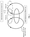
- FIG. 1 illustrates a relationship between the position of the power receiving coil (secondary coil shown by broken line or single-dot dashed line) with respect to the power supply coil (primary coil shown by solid line) and an interlinkage magnetic flux.
- the power supply coil and the power receiving coil have an identical shape.
- Position A the position of the power receiving coil where the central axis of the power supply coil (not shown) overlaps the central axis of the power receiving coil (not shown) is Position A
- Position B the position of the power receiving coil shifted by half the coil diameter from Position A.
- the orientation of the interlinking magnetic flux changes between a case where the power receiving coil that receives a magnetic flux generated from the power supply coil is located at Position A and a case where the power receiving coil is located at Position B.
- the magnetic flux is interlinked in such a way that the magnetic flux is canceled out, so that no current flows through the power receiving coil and the power supplied becomes 0 (null point).
- FIG. 2A illustrates a power supply characteristic with respect to a displacement between the power supply coil and the power receiving coil.
- the horizontal axis represents displacement d2 [cm] of the power receiving coil with respect to the power supply coil and the vertical axis represents the degree of coupling [dB].
- the power supply coil and the power receiving coil have the same coil diameter of 50 [cm].
- FIG. 2B shows that when the power receiving coil is located at Position B (that is, position shifted by half the coil diameter (25 [cm]) from Position A with respect to the power supply coil, the degree of coupling, that is, supplied power becomes 0 (null point), and power supply efficiency drastically decreases.
- An object of the present invention is to provide a power supply apparatus, a power receiving apparatus and a power supply system capable of preventing deterioration of power supply efficiency by increasing an allowable range of displacements of a power receiving coil with respect to a power supply coil, while facilitating mounting of the power receiving coil on the vehicle.
- a power supply apparatus supplies power to a vehicle including a power receiving coil, using an electromagnetic force, the power supply apparatus including a power supply coil that faces the power receiving coil and that supplies power, in which the power supply coil has a shape substantially identical to that of the power receiving coil, and has a first length longer than a second length, the first length being a length of the vehicle in a left and right direction of the vehicle, the second length being a length of the vehicle in a front and rear direction of the vehicle.
- a power receiving apparatus is provided on a vehicle and receives power supply from a power supply apparatus comprising a power supply coil, using an electromagnetic force, the power receiving apparatus including a power receiving coil that faces the power supply coil and receives power supply, in which the power receiving coil has a shape substantially identical to that of the power supply coil, and has a first length longer than a second length, the first length being a length of the vehicle in a left and right direction of the vehicle, the second length being a length of the vehicle in a front and rear direction of the vehicle.
- a power supply system includes: a power receiving apparatus provided on a vehicle; and a power supply apparatus that supplies power to the vehicle using an electromagnetic force, in which the power receiving apparatus comprises a power receiving coil that faces the power supply apparatus and receives power supply, the power supply apparatus includes a power supply coil that faces the power receiving coil and supplies power, and the power receiving coil and the power supply coil have shapes substantially identical with each other, and have lengths in a left and right direction of the vehicle, the lengths being longer than lengths of the power receiving coil and the power supply coil in a front and rear direction of the vehicle.
- the present invention it is possible to prevent deterioration of power supply efficiency by increasing the allowable range of displacements of the power receiving coil with respect to the power supply coil, while facilitating mounting of the power receiving coil on the vehicle.
- FIG. 3 is a block diagram illustrating a configuration of power supply system 10 according to the embodiment of the present invention.
- Power supply system 10 includes power supply apparatus 100, vehicle 130, power receiving apparatus 150 and storage battery 170.
- Power supply apparatus 100 is installed on or buried in the ground so that power supply section 103 is exposed from ground surface g. Power supply apparatus 100 is provided, for example, in a parking space, so as to face power receiving section 153, and supplies power to power receiving apparatus 150 (power receiving section 153) while vehicle 130 is parked.
- Vehicle 130 includes power receiving apparatus 150 and storage battery 170, and runs using storage battery 170 as a power source.
- Vehicle 130 is an automobile that runs on power of storage battery 170 such as a plug-in hybrid electric vehicle (PHEV) or an electric vehicle (EV).
- PHEV plug-in hybrid electric vehicle
- EV electric vehicle
- Power receiving apparatus 150 supplies the power supplied from power supply apparatus 100 to storage battery 170.
- Storage battery 170 stores the power supplied from power receiving apparatus 150.
- Power supply apparatus 100 includes power-supply-side communication section 101, power-supply-side control section 102 and power supply section 103.
- Power-supply-side communication section 101 receives a power-supply-start signal (charge-start signal) or a power-supply-stop signal (charge-stop signal) from vehicle-side communication section 152. Power-supply-side communication section 101 outputs the received power-supply-start signal or power-supply-stop signal to power-supply-side control section 102.
- Power-supply-side control section 102 controls power supply section 103 so as to start power supply according to the power-supply-start signal inputted from power-supply-side communication section 101.
- Power-supply-side control section 102 controls power supply section 103 so as to stop power supply according to the power-supply-stop signal inputted from power-supply-side communication section 101.
- Power supply section 103 includes power supply coil 103a.
- Power supply section 103 supplies a current at a predetermined frequency to power supply coil 103a under the control of power-supply-side control section 102, and thereby supplies power to power receiving section 153 using an electromagnetic force.
- This power supply is performed according to an electromagnetic induction scheme or a magnetic resonance scheme (magnetic field resonance scheme), for example. Note that details of the configuration of power supply coil 103a will be described later.
- Power receiving apparatus 150 includes vehicle-side control section 151, vehicle-side communication section 152 and power receiving section 153.
- Vehicle-side control section 151 controls vehicle-side communication section 152 and power receiving section 153 so as to perform various processes associated with starting of charging (power receiving), various processes associated with stopping of charging or various processes associated with power supply to storage battery 170.
- Vehicle-side communication section 152 generates a charge-start signal (power-supply-start signal) or a charge-stop signal (power-supply-stop signal) under the control of vehicle-side control section 151 and transmits the generated charge-start signal or charge-stop signal to power-supply-side communication section 101.
- Power receiving section 153 is provided at the bottom of vehicle 130, includes power receiving coil 153a and faces power supply section 103 in a wireless state when storage battery 170 is charged. Power receiving section 153 supplies the power supplied from power supply section 103 to power receiving coil 153a to storage battery 170 under the control of vehicle-side control section 151. Note that details of the configuration of power receiving coil 153a will be described later.
- FIG. 4 is a diagram illustrating a configuration of power supply coil 103a and power receiving coil 153a.
- FIG. 5 is a plan view illustrating, as an example, power supply system 10 when vehicle 130 is moving to a position to receive power supply in a parking space in which power supply apparatus 100 is installed.
- power supply coil 103a and power receiving coil 153a have a substantially identical shape (identical size) to achieve maximum power supply efficiency.
- power supply coil 103a and power receiving coil 153a are each a planar spiral coil.
- Length W is a length of power supply coil 103a in a length direction of the parking space and is a length of power receiving coil 153a in a moving direction (front and rear direction) of vehicle 130.
- Length L is a length of power supply coil 103a in a width direction of the parking space, and is a length of power receiving coil 153a in a direction (left and right direction) orthogonal to the front and rear direction of vehicle 130.
- L is longer than W. That is, power supply coil 103a and power receiving coil 153a each have a rectangular or elliptical shape, for example.
- FIG. 6 a position at which vehicle 130 is parked with car-stop 201 in contact with rear wheels of vehicle 130 (position shown by single-dot dashed line) is designated as a target stop position in the front and rear direction of vehicle 130 when power is supplied.
- FIG. 6 shows a state in which vehicle 130 is located at a position displaced from the target stop position (single-dot dashed line) by an allowable width of displacement (allowable displacement width in the front and rear direction; dotted line) in the front and rear direction of vehicle 130.
- Providing car-stop 201 in this way makes it easier to identify the stop position in the front and rear direction of vehicle 130.
- a displacement of power receiving coil 153a with respect to power supply coil 103a in the front and rear direction of vehicle 130 is generally assumed to be ⁇ 5 [cm] and a displacement of power receiving coil 153a with respect to power supply coil 103a in the left and right direction of vehicle 130 is generally assumed to be ⁇ 15 [cm].
- length L (coil length in the left and right direction) is 60 [cm] and length W (coil length in the front and rear direction) is 20 [cm], for example. That is, length L and length W are set to lengths four times the displacements assumed in the respective directions.
- a null point of supplied power is generated when a displacement in each direction becomes half the coil diameter.
- a displacement corresponding to a null point of supplied power is a length two times a maximum displacement (left and right direction: ⁇ 15 [cm], front and rear direction: ⁇ 5 [cm]) assumed in power receiving coil 153a.
- a maximum displacement assumed in power receiving coil 153a.
- the sizes of power supply coil 103a and power receiving coil 153a are set (here, four times the displacements assumed) so that the displacement corresponding to the null point of supplied power becomes sufficiently large (two times here). By so doing, it is possible to improve the power supply efficiency while preventing the supplied power from falling into a null point due to a displacement of power receiving coil 153a when vehicle 130 is parked.
- power supply coil 103a and power receiving coil 153a have an identical shape (that is, a symmetric shape), it is possible to increase power supply efficiency.
- true-circle power supply and power receiving coils are used (e.g., see PTL 1).
- the present embodiment uses landscape shaped (shape that satisfies L>W) power supply coil 103a and power receiving coil 153a.
- a displacement in the left and right direction of a vehicle is generally assumed to be larger than a displacement in the front and rear direction when the vehicle is parked.
- making length L in the left and right direction of vehicle 130 larger than length W in the front and rear direction as in the present embodiment rather than the conventional true-circle shape is more effective in preventing the above-described null point.
- adopting the landscape shape (L>W) as in the present embodiment is more appropriate than adopting a true-circle shape.
- the present embodiment can prevent deterioration of power supply efficiency by widening the allowable range of displacements of the power receiving coil with respect to the power supply coil, while facilitating mounting of the power receiving coil on the vehicle.
- the power supply apparatus, the power receiving apparatus and the power supply system according to the present invention are suitable for use in supplying power, in a wireless manner, to a power receiving section provided on the vehicle.
Landscapes
- Engineering & Computer Science (AREA)
- Power Engineering (AREA)
- Transportation (AREA)
- Mechanical Engineering (AREA)
- Computer Networks & Wireless Communication (AREA)
- Life Sciences & Earth Sciences (AREA)
- Sustainable Development (AREA)
- Sustainable Energy (AREA)
- Electric Propulsion And Braking For Vehicles (AREA)
- Charge And Discharge Circuits For Batteries Or The Like (AREA)
Abstract
Description
- The present invention relates to a power supply apparatus that supplies power to a power receiving coil provided on a vehicle using an electromagnetic force, and also relates to a power receiving apparatus and a power supply system.
- Conventionally, a wireless power supply apparatus is known which is installed on the ground and supplies power to a vehicle-mounted power receiving section (e.g., Patent Literature 1 (hereinafter, referred to as "PTL 1")).
- The power supply apparatus in PTL 1 includes two units; a power transmission unit and a power receiving unit. The power transmission unit accommodates a true-circle power transmission coil and is provided on a road side of a parking space or the like at a position where the vehicle is parked. The power receiving unit accommodates a true-circle power receiving coil, and is provided on the bottom surface of the vehicle at a position opposite to the power transmission unit installed on the ground.
- Japanese Patent Application Laid-Open No.
2011-10435 - A positional relationship between the power transmission coil (may also be called "power supply coil") and the power receiving coil during supply of power may cause deterioration of power supply efficiency. For example,
FIG. 1 illustrates a relationship between the position of the power receiving coil (secondary coil shown by broken line or single-dot dashed line) with respect to the power supply coil (primary coil shown by solid line) and an interlinkage magnetic flux. InFIG. 1 , it is assumed that the power supply coil and the power receiving coil have an identical shape. Suppose that the position of the power receiving coil where the central axis of the power supply coil (not shown) overlaps the central axis of the power receiving coil (not shown) is Position A, and the position of the power receiving coil shifted by half the coil diameter from Position A is Position B. As shown inFIG. 1 , the orientation of the interlinking magnetic flux changes between a case where the power receiving coil that receives a magnetic flux generated from the power supply coil is located at Position A and a case where the power receiving coil is located at Position B. When the power receiving coil is located at Position B, the magnetic flux is interlinked in such a way that the magnetic flux is canceled out, so that no current flows through the power receiving coil and the power supplied becomes 0 (null point). -
FIG. 2A illustrates a power supply characteristic with respect to a displacement between the power supply coil and the power receiving coil. InFIG. 2A , the horizontal axis represents displacement d2 [cm] of the power receiving coil with respect to the power supply coil and the vertical axis represents the degree of coupling [dB]. InFIG. 2A , suppose that the power supply coil and the power receiving coil have the same coil diameter of 50 [cm]. It is observed inFIG. 2B that when the power receiving coil is located at Position B (that is, position shifted by half the coil diameter (25 [cm]) from Position A with respect to the power supply coil, the degree of coupling, that is, supplied power becomes 0 (null point), and power supply efficiency drastically decreases. - In order to prevent deterioration of power supply efficiency and increase the allowable range of displacements of the power receiving coil with respect to the power supply coil, it is necessary to increase the coil diameters of the power supply coil and the power receiving coil to an extent that even when a displacement of the power receiving coil with respect to the power supply coil occurs, this will not result in a null point of supplied power. However, increasing the diameter of the power receiving coil in the same true-circle shape as disclosed in PTL 1 increases the size of the power receiving coil, resulting in a problem in that it is difficult to mount the power receiving coil on a vehicle having a limited mounting space.
- An object of the present invention is to provide a power supply apparatus, a power receiving apparatus and a power supply system capable of preventing deterioration of power supply efficiency by increasing an allowable range of displacements of a power receiving coil with respect to a power supply coil, while facilitating mounting of the power receiving coil on the vehicle.
- A power supply apparatus according to an aspect of the present invention supplies power to a vehicle including a power receiving coil, using an electromagnetic force, the power supply apparatus including a power supply coil that faces the power receiving coil and that supplies power, in which the power supply coil has a shape substantially identical to that of the power receiving coil, and has a first length longer than a second length, the first length being a length of the vehicle in a left and right direction of the vehicle, the second length being a length of the vehicle in a front and rear direction of the vehicle.
- A power receiving apparatus according to an aspect of the present invention is provided on a vehicle and receives power supply from a power supply apparatus comprising a power supply coil, using an electromagnetic force, the power receiving apparatus including a power receiving coil that faces the power supply coil and receives power supply, in which the power receiving coil has a shape substantially identical to that of the power supply coil, and has a first length longer than a second length, the first length being a length of the vehicle in a left and right direction of the vehicle, the second length being a length of the vehicle in a front and rear direction of the vehicle.
- A power supply system according to an aspect of the present invention includes: a power receiving apparatus provided on a vehicle; and a power supply apparatus that supplies power to the vehicle using an electromagnetic force, in which the power receiving apparatus comprises a power receiving coil that faces the power supply apparatus and receives power supply, the power supply apparatus includes a power supply coil that faces the power receiving coil and supplies power, and the power receiving coil and the power supply coil have shapes substantially identical with each other, and have lengths in a left and right direction of the vehicle, the lengths being longer than lengths of the power receiving coil and the power supply coil in a front and rear direction of the vehicle.
- According to the present invention, it is possible to prevent deterioration of power supply efficiency by increasing the allowable range of displacements of the power receiving coil with respect to the power supply coil, while facilitating mounting of the power receiving coil on the vehicle.
-
-
FIG. 1 is a diagram illustrating a relationship between a position of a power receiving coil and an interlinkage magnetic flux; -
FIGS. 2A and 2B are diagrams illustrating a power supply characteristic corresponding to a displacement of the power receiving coil with respect to the power supply coil; -
FIG. 3 is a block diagram illustrating a configuration of a power supply system according to an embodiment of the present invention; -
FIG. 4 is a diagram illustrating a power supply coil and a power receiving coil according to the embodiment of the present invention; -
FIG. 5 is a plan view of a vehicle guiding system according to the embodiment of the present invention when the vehicle is parked at a position for receiving power supply; and -
FIG. 6 is a diagram illustrating a case where a car-stop is provided in the power supply system according to the embodiment of the present invention. - Hereinafter, an embodiment of the present invention will be described in detail with reference to the accompanying drawings.
-
FIG. 3 is a block diagram illustrating a configuration ofpower supply system 10 according to the embodiment of the present invention. -
Power supply system 10 includespower supply apparatus 100,vehicle 130,power receiving apparatus 150 andstorage battery 170. -
Power supply apparatus 100 is installed on or buried in the ground so thatpower supply section 103 is exposed from ground surface g.Power supply apparatus 100 is provided, for example, in a parking space, so as to facepower receiving section 153, and supplies power to power receiving apparatus 150 (power receiving section 153) whilevehicle 130 is parked. -
Vehicle 130 includespower receiving apparatus 150 andstorage battery 170, and runs usingstorage battery 170 as a power source.Vehicle 130 is an automobile that runs on power ofstorage battery 170 such as a plug-in hybrid electric vehicle (PHEV) or an electric vehicle (EV). -
Power receiving apparatus 150 supplies the power supplied frompower supply apparatus 100 tostorage battery 170. -
Storage battery 170 stores the power supplied frompower receiving apparatus 150. -
Power supply apparatus 100 includes power-supply-side communication section 101, power-supply-side control section 102 andpower supply section 103. - Power-supply-
side communication section 101 receives a power-supply-start signal (charge-start signal) or a power-supply-stop signal (charge-stop signal) from vehicle-side communication section 152. Power-supply-side communication section 101 outputs the received power-supply-start signal or power-supply-stop signal to power-supply-side control section 102. - Power-supply-
side control section 102 controlspower supply section 103 so as to start power supply according to the power-supply-start signal inputted from power-supply-side communication section 101. Power-supply-side control section 102 controlspower supply section 103 so as to stop power supply according to the power-supply-stop signal inputted from power-supply-side communication section 101. -
Power supply section 103 includes power supply coil 103a.Power supply section 103 supplies a current at a predetermined frequency topower supply coil 103a under the control of power-supply-side control section 102, and thereby supplies power to power receivingsection 153 using an electromagnetic force. This power supply is performed according to an electromagnetic induction scheme or a magnetic resonance scheme (magnetic field resonance scheme), for example. Note that details of the configuration ofpower supply coil 103a will be described later. -
Power receiving apparatus 150 includes vehicle-side control section 151, vehicle-side communication section 152 andpower receiving section 153. - Vehicle-
side control section 151 controls vehicle-side communication section 152 andpower receiving section 153 so as to perform various processes associated with starting of charging (power receiving), various processes associated with stopping of charging or various processes associated with power supply tostorage battery 170. - Vehicle-
side communication section 152 generates a charge-start signal (power-supply-start signal) or a charge-stop signal (power-supply-stop signal) under the control of vehicle-side control section 151 and transmits the generated charge-start signal or charge-stop signal to power-supply-side communication section 101. -
Power receiving section 153 is provided at the bottom ofvehicle 130, includespower receiving coil 153a and facespower supply section 103 in a wireless state whenstorage battery 170 is charged.Power receiving section 153 supplies the power supplied frompower supply section 103 to power receivingcoil 153a tostorage battery 170 under the control of vehicle-side control section 151. Note that details of the configuration ofpower receiving coil 153a will be described later. -
FIG. 4 is a diagram illustrating a configuration ofpower supply coil 103a andpower receiving coil 153a.FIG. 5 is a plan view illustrating, as an example,power supply system 10 whenvehicle 130 is moving to a position to receive power supply in a parking space in whichpower supply apparatus 100 is installed. - Here, the more magnetic fluxes interlink with both the power supply coil (primary coil) and the power receiving coil (secondary coil), the higher the power supply efficiency becomes. Therefore, when the power supply coil and the power receiving coil are in an asymmetric shape (that is, having different shapes), this may result in deterioration of power supply efficiency, and so the power supply coil and the power receiving coil are preferably in a symmetric shape (that is, having an identical shape). Thus, as shown in
FIG. 4 andFIG. 5 ,power supply coil 103a andpower receiving coil 153a have a substantially identical shape (identical size) to achieve maximum power supply efficiency. - For example, as shown in
FIG. 4 ,power supply coil 103a andpower receiving coil 153a are each a planar spiral coil. - In
FIG. 5 , whenvehicle 130 is stopped at a position (target stop position) where the vehicle is supposed, in a design stage, to receive power supply,power supply coil 103a andpower receiving coil 153a are installed in the parking space and on the bottom surface invehicle 130 respectively so thatpower supply coil 103a andpower receiving coil 153a overlap each other in a plan view. In other words, at the target stop position ofvehicle 130 when power is supplied, whenpower supply coil 103a is projected ontopower receiving section 153 toward the direction ofpower receiving coil 153a,power supply coil 103a andpower receiving coil 153a substantially overlap each other. - Length W is a length of
power supply coil 103a in a length direction of the parking space and is a length ofpower receiving coil 153a in a moving direction (front and rear direction) ofvehicle 130. Length L is a length ofpower supply coil 103a in a width direction of the parking space, and is a length ofpower receiving coil 153a in a direction (left and right direction) orthogonal to the front and rear direction ofvehicle 130. - In
power supply coil 103a andpower receiving coil 153a, L is longer than W. That is,power supply coil 103a andpower receiving coil 153a each have a rectangular or elliptical shape, for example. - Next, a relationship between length L and length W will be described.
- A case will be described below as an example where a car-stop (wheel stopper) member is installed in the parking space as shown in
FIG. 6 . - More specifically, as shown in
FIG. 6 , a position at whichvehicle 130 is parked with car-stop 201 in contact with rear wheels of vehicle 130 (position shown by single-dot dashed line) is designated as a target stop position in the front and rear direction ofvehicle 130 when power is supplied. Note thatFIG. 6 shows a state in whichvehicle 130 is located at a position displaced from the target stop position (single-dot dashed line) by an allowable width of displacement (allowable displacement width in the front and rear direction; dotted line) in the front and rear direction ofvehicle 130. - Providing car-
stop 201 in this way makes it easier to identify the stop position in the front and rear direction ofvehicle 130. Thus, it is possible to reduce the displacement ofpower receiving coil 153a with respect topower supply coil 103a (displacement from the target stop position) in the front and rear direction ofvehicle 130 compared to the left and right direction. That is, it is possible to narrow the allowable range of displacement in the front and rear direction (allowable displacement width in the front and rear direction) ofvehicle 130 shown inFIG. 6 compared to the allowable displacement range in the left and right direction (allowable displacement width in the left and right direction). - Thus, the following description assumes a case where a displacement of
power receiving coil 153a in the front and rear direction of vehicle 130 (displacement from the target stop position in the front and rear direction) is smaller than a displacement ofpower receiving coil 153a in the left and right direction of vehicle 130 (displacement from the target stop position in the left and right direction). - For example, when
vehicle 130 is parked in the parking space in whichpower supply section 103 is installed, a displacement ofpower receiving coil 153a with respect topower supply coil 103a in the front and rear direction ofvehicle 130 is generally assumed to be ±5 [cm] and a displacement ofpower receiving coil 153a with respect topower supply coil 103a in the left and right direction ofvehicle 130 is generally assumed to be ±15 [cm]. - In this case, suppose length L (coil length in the left and right direction) is 60 [cm] and length W (coil length in the front and rear direction) is 20 [cm], for example. That is, length L and length W are set to lengths four times the displacements assumed in the respective directions.
- As described above, with reference to
FIGS. 1 and2 , a null point of supplied power is generated when a displacement in each direction becomes half the coil diameter. Thus, when L=60 [cm] and W=20 [cm], it is when the displacement is 30 [cm] that a null point of supplied power is generated in the left and right direction and it is when the displacement is 10 [cm] that a null point of supplied power is generated in the front and rear direction. - That is, a displacement corresponding to a null point of supplied power is a length two times a maximum displacement (left and right direction: ±15 [cm], front and rear direction: ±5 [cm]) assumed in
power receiving coil 153a. Thus, even when a maximum displacement is generated betweenpower supply coil 103a andpower receiving coil 153a, the supplied power does not fall into a null point in any direction. - A power supply characteristic at the maximum displacement assumed here (half the displacement corresponding to the null point) corresponds to, for example, a power supply characteristic (approximately -5 [dB]) near displacement d2=12.5 [cm] with a power supply characteristic in
FIG. 2 (coil diameter = 50 [cm], position corresponding to the null point d2=25 [cm]) (that is, half the displacement corresponding to the null point). That is, by setting L and W so that the assumed displacement ofpower receiving coil 153a becomes a length half the displacement where a null point of supplied power is generated (that is, to be sufficiently short), it is possible to avoid the system from falling into a low power supply characteristic near the null point (e.g., around 25 [cm] inFIG. 2 ) and achieve a high power supply characteristic. - In this way, the sizes of
power supply coil 103a andpower receiving coil 153a are set (here, four times the displacements assumed) so that the displacement corresponding to the null point of supplied power becomes sufficiently large (two times here). By so doing, it is possible to improve the power supply efficiency while preventing the supplied power from falling into a null point due to a displacement ofpower receiving coil 153a whenvehicle 130 is parked. - The size of
power supply coil 103a andpower receiving coil 153a in the left and right direction of vehicle 130 (width direction of the parking space) (e.g., L=60 [cm]) is larger than that in the front and rear direction of vehicle 130 (length direction of the parking space) (e.g., W=20 [cm]). It is thereby possible to increase the allowable range of displacement in the left and right direction where displacement is more likely to occur compared to the front and rear direction ofvehicle 130, thus avoiding a null point of supplied power due to a displacement in the left and right direction. - On the other hand, the size of
power supply coil 103a andpower receiving coil 153a in the front and rear direction of vehicle 130 (e.g., W=20 [cm]) is shorter than that in the left and right direction of vehicle 130 (e.g., L=60 [cm]). That is,vehicle 130 can be provided withpower receiving coil 153a that has a long axis in the left and right direction. In this way, even when the size ofpower receiving coil 153a is increased to widen the allowable range of displacement, it is possible to suppress an increase in the size in the front and rear direction ofvehicle 130. In the present embodiment, it is easier to mountpower receiving coil 153a on a vehicle having a limited mounting space for the power receiving coil compared to the related art. - Moreover, since
power supply coil 103a andpower receiving coil 153a have an identical shape (that is, a symmetric shape), it is possible to increase power supply efficiency. - Conventionally, true-circle power supply and power receiving coils are used (e.g., see PTL 1). In contrast, the present embodiment uses landscape shaped (shape that satisfies L>W)
power supply coil 103a andpower receiving coil 153a. As described above, a displacement in the left and right direction of a vehicle is generally assumed to be larger than a displacement in the front and rear direction when the vehicle is parked. For this reason, when a coil is formed using the same winding, making length L in the left and right direction ofvehicle 130 larger than length W in the front and rear direction as in the present embodiment rather than the conventional true-circle shape is more effective in preventing the above-described null point. Thus, if the same winding is used, adopting the landscape shape (L>W) as in the present embodiment is more appropriate than adopting a true-circle shape. - For the above reasons, the present embodiment can prevent deterioration of power supply efficiency by widening the allowable range of displacements of the power receiving coil with respect to the power supply coil, while facilitating mounting of the power receiving coil on the vehicle.
-
- [1] A case has been described in the above-described embodiment as an example where
power supply coil 103a andpower receiving coil 153a have sizes four times the displacement assumed in each direction (that is, a size whereby a displacement corresponding to the null point of supplied power becomes two times the displacement assumed). However, the sizes ofpower supply coil 103a andpower receiving coil 153a are not limited to the above-described sizes. That is, the sizes ofpower supply coil 103a andpower receiving coil 153a may be set such that the displacement corresponding to the null point of supplied power is not included in the assumed range of displacement. More specifically, the sizes (L and W) ofpower supply coil 103a andpower receiving coil 153a may be at least greater than two times the assumed range of displacement of the power receiving coil from the target stop position. That is, half the coil diameter (corresponding to the null point) may exceed the assumed range of displacement. By so doing, it is possible to at least avoid the null point of supplied power even when a displacement ofpower receiving coil 153a inpower supply system 10 takes any value within the assumed range.
For example, when a displacement ofpower receiving coil 153a with respect topower supply coil 103a is assumed to be within ±5 [cm] in the front and rear direction ofvehicle 130 and is assumed to be within ±15 [cm] in the left and right direction ofvehicle 130, W may be longer than 10 [cm] and L may be longer than 30 [cm]. For example, a combination of numerical values of W=20, 40 [cm] (>10 [cm]) and L=60, 80 [cm] (>30 [cm]) may be adopted as the sizes ofpower supply coil 103a andpower receiving coil 153a. These numerical values may be set according to a settable size (vehicle width or the like of vehicle 130) ofpower receiving coil 153a invehicle 130, for example. - [2] A case has been described in the above-described embodiment where car-
stop 201 is provided as shown inFIG. 6 , but without being limited to the car-stop, a structure may be provided instead, which facilitates identification of a target stop position in the front and rear direction ofvehicle 130. For example, at the target stop position in the front and rear direction of vehicle 130 (position at whichpower supply coil 103a andpower receiving coil 153a face each other), grooves in which tires of vehicle 130 (front wheels or rear wheels) are fitted may be formed in the parking space (ground surface g). These grooves also correspond to a car-stop member. - [3] When a parking operation (e.g., operation of pulling the hand brake lever) is performed after the rear wheels of
vehicle 130 come into contact with car-stop 201,vehicle 130 may actually stop after slightly passing the contact position. Thus, the installation position ofpower supply coil 103a in the front and rear direction of the parking space and the installation position ofpower receiving coil 153a in the front and rear direction ofvehicle 130 may be set so that the position at which the rear wheels ofvehicle 130 come into contact with car-stop 201 becomes a maximum value of displacement assumed in the front and rear direction. That is, the position at whichvehicle 130 completely stops after the parking operation may be a target stop position in the front and rear direction of vehicle 130 (position at whichpower supply coil 103a andpower receiving coil 153a overlap each other in a plan view). By so doing, it is possible to improve power supply efficiency at the target stop position to a maximum. - [4] Although
FIG. 6 is shown as an exemplary installation location ofpower receiving coil 153a, the installation location ofpower receiving coil 153a is not limited toFIG. 6 , but may be the bottom part between the rear wheels ofvehicle 130, the bottom part of the trunk provided in the rear ofvehicle 130 or the bottom part between the front wheels ofvehicle 130 or the like. As the installation location ofpower receiving coil 153a,power receiving coil 153a can be installed on the ceiling surface ofvehicle 130. In this case,power supply section 103 is installed at a place located abovevehicle 130 such as the ceiling of a garage whenvehicle 130 is parked. - [5] As shown in
FIG. 3 , whenpower supply section 103 is installed on or buried in the ground so that it is exposed from ground surface g, the width of a casing ofpower supply section 103 itself may be set to a length corresponding to the tire width of vehicle 130 (e.g., width between the left and right tires). By so doing, for example, whenvehicle 130 enters the parking space in whichpower supply section 103 is installed, if the vehicle does not stop at an appropriate stop position,vehicle 130 runs onpower supply section 103, thus making it possible to notify the driver that it is not an appropriate stop position. This allowsvehicle 130 to stop at a target stop position appropriately. - The disclosure of Japanese Patent Application No.
2013-063966, filled on March 26, 2013 - The power supply apparatus, the power receiving apparatus and the power supply system according to the present invention are suitable for use in supplying power, in a wireless manner, to a power receiving section provided on the vehicle.
-
- 10
- Power supply system
- 100
- Power supply apparatus
- 101
- Power-supply-side communication section
- 102
- Power-supply-side control section
- 103
- Power supply section
- 103a
- Power supply coil
- 130
- Vehicle
- 150
- Power receiving apparatus
- 151
- Vehicle-side control section
- 152
- Vehicle-side communication section
- 153
- Power receiving section
- 153a
- Power receiving coil
- 170
- Storage battery
- 201
- Bumping post
Claims (7)
- A power supply apparatus that supplies power to a vehicle including a power receiving coil, using an electromagnetic force, the power supply apparatus comprising a power supply coil that faces the power receiving coil and that supplies power, wherein
the power supply coil has a shape substantially identical to that of the power receiving coil, and has a first length longer than a second length, the first length being a length of the vehicle in a left and right direction of the vehicle, the second length being a length of the vehicle in a front and rear direction of the vehicle. - The power supply apparatus according to claim 1, wherein,
when the power supply coil is projected onto the power receiving coil toward a direction of the power receiving coil at a target stop position of the vehicle where the vehicle is supplied with power, the power supply coil and the power receiving coil substantially overlap each other, and
the target stop position of the vehicle in the front and rear direction is a position where the vehicle stops while a rear wheel of the vehicle is in contact with a car-stop member. - The power supply apparatus according to claim 1, wherein,
when an assumed range of displacements of the power receiving coil from the target stop position is equal to or less than a third length in the front and rear direction of the vehicle and is equal to or less than a fourth length in the left and right direction of the vehicle, the first length is greater than at least twice the third length, and the second length is greater than at least twice the fourth length. - The power supply apparatus according to claim 1, wherein the power supply coil is a spiral coil.
- A power receiving apparatus that is provided on a vehicle and that receives power supply from a power supply apparatus comprising a power supply coil, using an electromagnetic force, the power receiving apparatus comprising a power receiving coil that faces the power supply coil and receives power supply, wherein
the power receiving coil has a shape substantially identical to that of the power supply coil, and has a first length longer than a second length, the first length being a length of the vehicle in a left and right direction of the vehicle, the second length being a length of the vehicle in a front and rear direction of the vehicle. - The power receiving apparatus according to claim 5, wherein the power receiving coil is a spiral coil.
- A power supply system comprising:a power receiving apparatus provided on a vehicle; anda power supply apparatus that supplies power to the vehicle using an electromagnetic force, whereinthe power receiving apparatus comprises a power receiving coil that faces the power supply apparatus and receives power supply,the power supply apparatus comprises a power supply coil that faces the power receiving coil and supplies power, andthe power receiving coil and the power supply coil have shapes substantially identical with each other, and have lengths in a left and right direction of the vehicle, the lengths being longer than lengths of the power receiving coil and the power supply coil in a front and rear direction of the vehicle.
Applications Claiming Priority (2)
| Application Number | Priority Date | Filing Date | Title |
|---|---|---|---|
| JP2013063966A JP2014192939A (en) | 2013-03-26 | 2013-03-26 | Power supply apparatus, power receiver unit and power supply system |
| PCT/JP2014/001675 WO2014156107A1 (en) | 2013-03-26 | 2014-03-24 | Power supplying device, power receiving device, and power supplying system |
Publications (2)
| Publication Number | Publication Date |
|---|---|
| EP2985872A1 true EP2985872A1 (en) | 2016-02-17 |
| EP2985872A4 EP2985872A4 (en) | 2016-04-06 |
Family
ID=51623120
Family Applications (1)
| Application Number | Title | Priority Date | Filing Date |
|---|---|---|---|
| EP14773722.5A Withdrawn EP2985872A4 (en) | 2013-03-26 | 2014-03-24 | Power supplying device, power receiving device, and power supplying system |
Country Status (5)
| Country | Link |
|---|---|
| US (1) | US20160052406A1 (en) |
| EP (1) | EP2985872A4 (en) |
| JP (1) | JP2014192939A (en) |
| CN (1) | CN105052012A (en) |
| WO (1) | WO2014156107A1 (en) |
Families Citing this family (8)
| Publication number | Priority date | Publication date | Assignee | Title |
|---|---|---|---|---|
| JP6354565B2 (en) * | 2014-12-19 | 2018-07-11 | Tdk株式会社 | Power receiving device |
| JP2018064441A (en) * | 2016-10-11 | 2018-04-19 | 本田技研工業株式会社 | Non-contact power supply system and power transmission device, and design method and installation method of power transmission device |
| US10464442B2 (en) | 2016-10-11 | 2019-11-05 | Honda Motor Co., Ltd. | Non-contact power supply system and power transmission apparatus, and designing method and installing method of power transmission apparatus |
| JP2018121036A (en) * | 2017-01-27 | 2018-08-02 | 京セラ株式会社 | Non-contact power transmission device |
| WO2018195330A1 (en) | 2017-04-19 | 2018-10-25 | Chase Arnold | Intelligent vehicle charging equipment |
| US10988042B1 (en) | 2018-10-12 | 2021-04-27 | Arnold Chase | Vehicle charging system |
| US11485246B1 (en) | 2021-04-05 | 2022-11-01 | Arnold Chase | Individualized vehicular charging mat |
| US12024039B2 (en) | 2021-12-07 | 2024-07-02 | Arnold Chase | Vehicle self-centered charging system |
Family Cites Families (13)
| Publication number | Priority date | Publication date | Assignee | Title |
|---|---|---|---|---|
| US5703461A (en) * | 1995-06-28 | 1997-12-30 | Kabushiki Kaisha Toyoda Jidoshokki Seisakusho | Inductive coupler for electric vehicle charger |
| JPH09182212A (en) * | 1995-12-25 | 1997-07-11 | Toyota Autom Loom Works Ltd | Automatic charging device |
| JP5054113B2 (en) * | 2007-09-17 | 2012-10-24 | 秀雄 菊地 | Inductive power transmission circuit |
| US20100277121A1 (en) * | 2008-09-27 | 2010-11-04 | Hall Katherine L | Wireless energy transfer between a source and a vehicle |
| JP2011010435A (en) | 2009-06-25 | 2011-01-13 | Fujitsu Ten Ltd | Contactless power supply system and contactless power supply unit |
| JP5622518B2 (en) * | 2009-10-14 | 2014-11-12 | パナソニック株式会社 | Electric machine and battery system with battery pack |
| JP5506327B2 (en) * | 2009-10-27 | 2014-05-28 | 株式会社ヘッズ | Non-contact power supply device |
| JP2011106216A (en) * | 2009-11-20 | 2011-06-02 | Autonetworks Technologies Ltd | Wireless power feeder for vehicle |
| AU2011224345A1 (en) * | 2010-03-10 | 2012-11-01 | Witricity Corporation | Wireless energy transfer converters |
| US10343535B2 (en) * | 2010-04-08 | 2019-07-09 | Witricity Corporation | Wireless power antenna alignment adjustment system for vehicles |
| WO2012090612A1 (en) * | 2010-12-27 | 2012-07-05 | 日産自動車株式会社 | Non-contact charging device |
| JP2013002085A (en) * | 2011-06-14 | 2013-01-07 | Sumitomo Electric Ind Ltd | Parking system and car stop |
| JP2013211932A (en) * | 2012-03-30 | 2013-10-10 | Equos Research Co Ltd | Power transmission system |
-
2013
- 2013-03-26 JP JP2013063966A patent/JP2014192939A/en active Pending
-
2014
- 2014-03-24 US US14/779,411 patent/US20160052406A1/en not_active Abandoned
- 2014-03-24 EP EP14773722.5A patent/EP2985872A4/en not_active Withdrawn
- 2014-03-24 WO PCT/JP2014/001675 patent/WO2014156107A1/en active Application Filing
- 2014-03-24 CN CN201480017661.3A patent/CN105052012A/en active Pending
Also Published As
| Publication number | Publication date |
|---|---|
| CN105052012A (en) | 2015-11-11 |
| WO2014156107A1 (en) | 2014-10-02 |
| JP2014192939A (en) | 2014-10-06 |
| US20160052406A1 (en) | 2016-02-25 |
| EP2985872A4 (en) | 2016-04-06 |
Similar Documents
| Publication | Publication Date | Title |
|---|---|---|
| EP2985872A1 (en) | Power supplying device, power receiving device, and power supplying system | |
| JP6427873B2 (en) | Parking assistance device and system | |
| US10576842B2 (en) | Electricity supply apparatus and electricity reception apparatus | |
| US10279692B2 (en) | Electricity supply device and electricity reception device | |
| US9027723B2 (en) | Vehicle electric power supply system | |
| JP5506327B2 (en) | Non-contact power supply device | |
| CN105429250B (en) | Method and apparatus for wireless charging system | |
| US9577464B2 (en) | Wireless charging system | |
| EP2985163B1 (en) | Contactless power supply device | |
| EP3131174A1 (en) | Non-contact power supply coil | |
| US20140306655A1 (en) | Contactless battery charger | |
| US8970167B2 (en) | Vehicle charging induction loop incorporated into section of roadway in proximity to traffic stop locations | |
| JP2010035333A (en) | Traveling charging apparatus and traveling charging method | |
| US9979229B2 (en) | Power supply apparatus | |
| US20190319497A1 (en) | Power-feeding device | |
| EP3282556B1 (en) | Non-contact power-feeding system | |
| WO2013099222A1 (en) | Non-contact charging device | |
| CN205070484U (en) | A equipment for wireless charging system | |
| WO2013136787A1 (en) | Electricity supply device, electricity reception device, and electricity supply system | |
| US10286796B2 (en) | Vehicle, vehicle charging apparatus, vehicle charging system, and vehicle charging method | |
| JP2013009479A (en) | Power supply device, power receiving device, mobile, power charging system, and power supply method | |
| CN109664781B (en) | Method and apparatus for transmitting wireless power to electric vehicle and electric vehicle | |
| US20180099569A1 (en) | Power transmission apparatus | |
| US9748773B2 (en) | Contactless power supply device | |
| JP2011115017A (en) | Radio power supply system and method for designing the same |
Legal Events
| Date | Code | Title | Description |
|---|---|---|---|
| PUAI | Public reference made under article 153(3) epc to a published international application that has entered the european phase |
Free format text: ORIGINAL CODE: 0009012 |
|
| 17P | Request for examination filed |
Effective date: 20150921 |
|
| AK | Designated contracting states |
Kind code of ref document: A1 Designated state(s): AL AT BE BG CH CY CZ DE DK EE ES FI FR GB GR HR HU IE IS IT LI LT LU LV MC MK MT NL NO PL PT RO RS SE SI SK SM TR |
|
| AX | Request for extension of the european patent |
Extension state: BA ME |
|
| A4 | Supplementary search report drawn up and despatched |
Effective date: 20160308 |
|
| RIC1 | Information provided on ipc code assigned before grant |
Ipc: H02J 7/00 20060101ALI20160302BHEP Ipc: B60L 5/00 20060101ALI20160302BHEP Ipc: B60L 11/14 20060101ALI20160302BHEP Ipc: B60L 11/18 20060101ALI20160302BHEP Ipc: H02J 50/00 20160101AFI20160302BHEP |
|
| DAX | Request for extension of the european patent (deleted) | ||
| RIC1 | Information provided on ipc code assigned before grant |
Ipc: B60L 5/00 20060101ALI20160926BHEP Ipc: H02J 50/90 20160101ALI20160926BHEP Ipc: B60L 11/14 20060101ALI20160926BHEP Ipc: B60L 11/18 20060101ALI20160926BHEP Ipc: H02J 50/80 20160101ALI20160926BHEP Ipc: H02J 50/00 20160101AFI20160926BHEP Ipc: H02J 7/00 20060101ALI20160926BHEP Ipc: H02J 50/10 20160101ALI20160926BHEP |
|
| RIC1 | Information provided on ipc code assigned before grant |
Ipc: B60L 5/00 20060101ALI20161005BHEP Ipc: H02J 50/00 20160101AFI20161005BHEP Ipc: H02J 7/00 20060101ALI20161005BHEP Ipc: H02J 50/80 20160101ALI20161005BHEP Ipc: B60L 11/14 20060101ALI20161005BHEP Ipc: H02J 50/90 20160101ALI20161005BHEP Ipc: H02J 50/10 20160101ALI20161005BHEP Ipc: B60L 11/18 20060101ALI20161005BHEP |
|
| STAA | Information on the status of an ep patent application or granted ep patent |
Free format text: STATUS: THE APPLICATION HAS BEEN WITHDRAWN |
|
| 18W | Application withdrawn |
Effective date: 20180801 |