EP2985245B1 - Rollenangetriebene vorrichtung für rollenförderer - Google Patents
Rollenangetriebene vorrichtung für rollenförderer Download PDFInfo
- Publication number
- EP2985245B1 EP2985245B1 EP15175521.2A EP15175521A EP2985245B1 EP 2985245 B1 EP2985245 B1 EP 2985245B1 EP 15175521 A EP15175521 A EP 15175521A EP 2985245 B1 EP2985245 B1 EP 2985245B1
- Authority
- EP
- European Patent Office
- Prior art keywords
- roller
- flange
- ring
- wheel
- pulley
- Prior art date
- Legal status (The legal status is an assumption and is not a legal conclusion. Google has not performed a legal analysis and makes no representation as to the accuracy of the status listed.)
- Active
Links
Images


Classifications
-
- B—PERFORMING OPERATIONS; TRANSPORTING
- B65—CONVEYING; PACKING; STORING; HANDLING THIN OR FILAMENTARY MATERIAL
- B65G—TRANSPORT OR STORAGE DEVICES, e.g. CONVEYORS FOR LOADING OR TIPPING, SHOP CONVEYOR SYSTEMS OR PNEUMATIC TUBE CONVEYORS
- B65G39/00—Rollers, e.g. drive rollers, or arrangements thereof incorporated in roller-ways or other types of mechanical conveyors
- B65G39/02—Adaptations of individual rollers and supports therefor
-
- B—PERFORMING OPERATIONS; TRANSPORTING
- B65—CONVEYING; PACKING; STORING; HANDLING THIN OR FILAMENTARY MATERIAL
- B65G—TRANSPORT OR STORAGE DEVICES, e.g. CONVEYORS FOR LOADING OR TIPPING, SHOP CONVEYOR SYSTEMS OR PNEUMATIC TUBE CONVEYORS
- B65G39/00—Rollers, e.g. drive rollers, or arrangements thereof incorporated in roller-ways or other types of mechanical conveyors
-
- B—PERFORMING OPERATIONS; TRANSPORTING
- B23—MACHINE TOOLS; METAL-WORKING NOT OTHERWISE PROVIDED FOR
- B23K—SOLDERING OR UNSOLDERING; WELDING; CLADDING OR PLATING BY SOLDERING OR WELDING; CUTTING BY APPLYING HEAT LOCALLY, e.g. FLAME CUTTING; WORKING BY LASER BEAM
- B23K37/00—Auxiliary devices or processes, not specially adapted for a procedure covered by only one of the other main groups of this subclass
-
- B—PERFORMING OPERATIONS; TRANSPORTING
- B65—CONVEYING; PACKING; STORING; HANDLING THIN OR FILAMENTARY MATERIAL
- B65G—TRANSPORT OR STORAGE DEVICES, e.g. CONVEYORS FOR LOADING OR TIPPING, SHOP CONVEYOR SYSTEMS OR PNEUMATIC TUBE CONVEYORS
- B65G13/00—Roller-ways
- B65G13/02—Roller-ways having driven rollers
-
- B—PERFORMING OPERATIONS; TRANSPORTING
- B65—CONVEYING; PACKING; STORING; HANDLING THIN OR FILAMENTARY MATERIAL
- B65G—TRANSPORT OR STORAGE DEVICES, e.g. CONVEYORS FOR LOADING OR TIPPING, SHOP CONVEYOR SYSTEMS OR PNEUMATIC TUBE CONVEYORS
- B65G13/00—Roller-ways
- B65G13/02—Roller-ways having driven rollers
- B65G13/04—Roller-ways having driven rollers all rollers driven
-
- B—PERFORMING OPERATIONS; TRANSPORTING
- B65—CONVEYING; PACKING; STORING; HANDLING THIN OR FILAMENTARY MATERIAL
- B65G—TRANSPORT OR STORAGE DEVICES, e.g. CONVEYORS FOR LOADING OR TIPPING, SHOP CONVEYOR SYSTEMS OR PNEUMATIC TUBE CONVEYORS
- B65G13/00—Roller-ways
- B65G13/02—Roller-ways having driven rollers
- B65G13/06—Roller driving means
- B65G13/07—Roller driving means having endless driving elements
-
- B—PERFORMING OPERATIONS; TRANSPORTING
- B65—CONVEYING; PACKING; STORING; HANDLING THIN OR FILAMENTARY MATERIAL
- B65G—TRANSPORT OR STORAGE DEVICES, e.g. CONVEYORS FOR LOADING OR TIPPING, SHOP CONVEYOR SYSTEMS OR PNEUMATIC TUBE CONVEYORS
- B65G39/00—Rollers, e.g. drive rollers, or arrangements thereof incorporated in roller-ways or other types of mechanical conveyors
- B65G39/02—Adaptations of individual rollers and supports therefor
- B65G39/09—Arrangements of bearing or sealing means
Definitions
- the present invention concerns the technical field of the roller conveyor for transporting goods possibly supported by frames, slides or pallets and it refers to a roller driven device, in other words to a motorized roller, for roller conveyors.
- Roller driven device are known, each of them comprising a tubular cylindrical roller supported, through bearing, by an axis or by another kind of support; each end of the roller is provided with a respective wheel or bushing (in the following the latter element will be named "wheel").
- Said known devices further comprise a single or double pulley fixed to the external surface of the cylindrical roller adjacent to one of the side wheels; said pulley usually is a timing pulley for a timing belts, and it transmits to the device the motion for the rotation of the device around the axis of the roller provided by the belt engaged to the drive pulley of an engine.
- the pulley is fixed more possible close to the respective wheel and it is fixed to the roller by means of an annular welding made at the external end, in other word the end closed to the wheel, of the pulley whose opposite end is not welded to preserve the roller strength in its area more affected by flexion and stresses; said solution avoids weakening of the roller but because of the close distance between the pulley and the adjacent inner flange of the wheel, do not allow to weld said inner flange to the roller on the contrary to the inner flange of the opposite wheel of the device.
- a drawback of said known solution consists in that, in the event of abnormal and/or very high and/or with axial components stresses, acting on the wheel adjacent to the pulley, the connection between said wheel and the roller could be damaged.
- the document US2008/010831 discloses a roller driven device having the features of the preamble of claim 1 and claim 2.
- roller driven device for roller conveyors comprising a tubular roller, freely rotating around its geometric axis and having at each end a respective lateral wheel each comprising a tubular cylindrical element 12b having an external protruding flange and an internal flange where the tubular cylindrical element and the two flanges are integral.
- Said roller driven device comprises a timing pulley adjacent to a first lateral wheel and a sleeve inside the timing pulley and to the first lateral wheel and containing a respective end of the tubular roller. Said end of the tubular roller is welded to the inner surface of the sleeve.
- the end of the sleeve can be welded inside the inner cavity of the first wheel (as shown in figures 1A and 1B of document US2006/102451 ) or to the side external surface of the external protruding flange of the first wheel (as shown in figures 2A and 2B of document US2006/102451 ); in this latter case the end of the roller and the respective welding to the inner surface of the sleeve is quite deep inside the sleeve, at least to leave space for the bearings.
- a further drawback of both solutions consists in that no direct welding or direct fixing are carried out between the roller and the first wheel.
- Another drawback of both solutions consists in that provide only one (indirect) connection between the roller and the first wheel.
- a further drawback of both solutions consists in that the end of the sleeve opposed to the first wheel must be welded to the roller close to the median portion thereof increasing the risks to weak the roller in said critical position.
- a drawback of the first known solution consists in that the first wheel must be solid to provide the welding surface and must be complex and expensive because of the bearing housing carried out in the body of the first wheel.
- a drawback of the second known solution consists in that the fixing of the first wheel to the roller is made by two sequential and spaced welding increasing the risk of mispositioning and/or misalignment.
- An object of the following claim 1 and claim 2 is to overcome the drawback of the second mentioned document.
- An object of the present invention is to propose a device that can support very strong stresses. Further object is to propose a device easy to be manufactured. Another object is to propose a device provided with very light weight but with strong side wheels.
- the end portion of the roller means 3 opposed to the second wheel means 5 is fixed to the central hole of the second flange means 7 of the first wheel means 4.
- the fixing of the outer surface of the ring means 11 to the central hole of the first flange means 8 is carried out between said outer surface of the ring means 11 and the surface of the first flange means 8 around the respective hole and opposite to the second flange means 7.
- the fixing of the end portion of the roller means 3 to the central hole of the second flange means 7 is carried out between the outer surface of the end portion of the roller means 3 and the surface of the second flange means 7 around the respective hole and opposite the first flange means 8.
- the roller means 3, the ring means 11 and at least the flanges means 8, 7 are made of metal, preferably of iron, and the fixings of the end of the ring means 11 to the outer surface of the roller means 3, of the outer surface of the ring means 11 to the surface of the first flange means 8 around the respective hole and opposite to the second flange means 7 and of the outer surface of the end portion of the tubular roller means 3 to the surface of the second flange means 7 around the respective hole and opposite to the first flange means 8, are carried out by the welding of the kind that provides melting of the base metal and addition to the joint of a metal filler material.
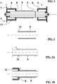
- the solution in object provides a double fixing of the first wheel to the roller means and one of said fixing is direct between the two parts and furthermore provides welded fixings only on the portion of the roller means 3 close to the first wheel means avoiding wildings in the most delicate portion of the roller means avoiding weakening of the latter.
- a further topic of the solution in object consists in that the wheel means can be made in a simple, light and cheap manner by welding to the each tubular cylindrical element 6 the two respective flange means. Furthermore the solution in object allows an adequate precision of the fixing without needs of special and expensive provisions.
- said annular means 11 is integral, or in other word in single body, with the pulley means 9 and protrudes outward an end of the latter.
- the roller means 3 is provided with an annulus shoulder, for instance carried out on the roller means by turning process; said annulus shoulder matches with the inner end portion of the pulley means opposed to the ring means centering, with reduced play, the pulley means in respect to the roller means 3.
- the pulley means 9 is timing type, preferably with two sets of teeth, for two not illustrated timing belts operated by an engine, for instance of electric kind.
- each tubular cylinder 6 of the wheel means 4, 5 is provided with a respective anti-slip synthetic coating and the second flange means 7 radially protrudes in respect to the respective tubular cylinder 6 to provide a guide or a side stopper for the load.
- the inner end portions of the roller means consist in a housing for respective bearings assigned to the free rotating support of the device.
- the ring means 11 consists in an independent tubular cylindrical element separated from the pulley means.
- the end of the pulley means 9 adjacent to the ring means 11 is fixed, by welding, to the outer surface of the roller means 3.
- the invention further provides that the ring means 11 is integral with the rolling means 3, in this case the ring means 11 can be carried out in the same phase and with the same tool for carrying out the annulus shoulder.
- the first flange means 8 of at least the first lateral wheel means 4 is concave shaped with the concavity facing the opposite second wheel means 5; consequently the central hole of the first flange means 8 is shifted toward the external end of the respective ring means 11.
- the welding between the first flange means 8 and the tubular cylindrical element 6 can be carried out at the inner end of the latter 6.
- This arrangement facilitates the welding of the first flange means 8 to the respective ring means 11 particularly when the latter 11 is integral with the pulley means 9 as illustrated in the figures 6 and 7 , and it facilitates the welding between the first flange means 8 and the respective tubular cylindrical element 6.
- the method to make the device provides:
Landscapes
- Engineering & Computer Science (AREA)
- Mechanical Engineering (AREA)
- Physics & Mathematics (AREA)
- Optics & Photonics (AREA)
- Rollers For Roller Conveyors For Transfer (AREA)
Claims (14)
- Rollengetriebene Vorrichtung für Rollenförderer, umfassend ein zylindrisches und ein rohrförmiges Rollenmittel (3), das um seine geometrische Achse rotiert und an jedem Ende ein entsprechendes erstes (4) und zweites (5) laterales Radmittel aufweist;
wobei zumindest das erste Radmittel ein rohrförmiges zylindrisches Element (6) aufweist, das an seinem dem zweiten Radmittel (5) zugewandten Ende ein erstes Flanschmittel (8) und an dem gegenüberliegenden Ende ein zweites Flanschmittel (7) aufweist, wobei beide Flanschmittel (8, 7) die Form eines Ringes aufweisen, wobei die Vorrichtung (1) ferner ein an der äußeren Oberfläche des Rollenmittels (3) benachbart zu dem ersten Radmittel (4) befestigtes Riemenscheibenmittel (9) aufweist, um über einen Riemen oder dergleichen eine axiale Rotationsbewegung auf die Vorrichtung zu übertragen;
und die Vorrichtung (1) ist dadurch gekennzeichnet, dass sie ein Ringmittel (11) umfasst, dessen axiale Länge zwei Drittel bis ein Zwanzigstel des axialen Abstands zwischen dem ersten (8) und dem zweiten Flanschmittel (7) des ersten Radmittels (4) beträgt, die äußere Oberfläche des Ringmittels (11) mit einem zentralen Loch des ersten Flanschmittels (8) in Eingriff steht und verschweißt ist, ein Ende des Ringmittels (11) zwischen dem ersten (8) und dem zweiten Flanschmittel (7) angeordnet ist und dieses Ende mit der äußeren Oberfläche des Rollenmittels (3) verschweißt ist, dessen Endbereich an dem zentralen Loch des zweiten Flanschmittels (7) befestigt ist. - Rollengetriebene Vorrichtung für Rollenförderer, umfassend ein zylindrisches und rohrförmiges Rollenmittel (3), das um seine geometrische Achse rotiert und an jedem Ende jeweils ein erstes (4) und ein zweites laterales Radmittel (5) aufweist;
wobei zumindest das erste Radmittel ein rohrförmiges zylindrisches Element (6) umfasst, das an seinem dem zweiten Radmittel (5) zugewandten Ende ein erstes Flanschmittel (8) und an dem gegenüberliegenden Ende ein zweites Flanschmittel (7) aufweist, wobei beide Flanschmittel (8, 7) die Form eines Ringes aufweisen, wobei die Vorrichtung (1) ferner ein an der äußeren Oberfläche des Rollenmittels (3) benachbart zu dem ersten Radmittel (4) befestigtes Riemenscheibenmittel (9) aufweist, um über einen Riemen oder dergleichen eine axiale Rotationsbewegung auf die Vorrichtung zu übertragen;
und die Vorrichtung (1) ist dadurch gekennzeichnet, dass sie ein Ringmittel (11) umfasst, das aus einem zylindrischen rohrförmigen Element besteht, das in einem einteiligen Körper mit dem Riemenscheibenmittel (9) realisiert ist und von dem Ende benachbart zu dem ersten Radmittel (4) vorsteht, wobei die axiale Länge des Ringmittels (11) zwei Drittel bis ein Zwanzigstel des axialen Abstands zwischen dem ersten (8) und dem zweiten Flanschmittel (7) des ersten Radmittels (4) beträgt, die äußere Oberfläche des Ringmittels (11) mit einem zentralen Loch des ersten Flanschmittels (8) in Eingriff steht und verschweißt ist, ein Ende des Ringmittels (11) zwischen dem ersten (8) und zweiten Flanschmittel (7) angeordnet ist und das Ende mit der äußeren Oberfläche des Rollenmittels (3) verschweißt ist, dessen Endbereich an dem zentralen Loch des zweiten Flanschmittels (7) befestigt ist. - Die Vorrichtung gemäß Anspruch 1 oder 2, dadurch gekennzeichnet, dass das Verschweißen der äußeren Oberfläche des Ringmittels (11) mit dem zentralen Loch des ersten Flanschmittels (8) zwischen der äußeren Oberfläche des Ringmittels (11) und der Oberfläche des ersten Flanschmittels (8) um das jeweilige Loch und entgegengesetzt zu dem zweiten Flanschmittel (7) durchgeführt wird.
- Die Vorrichtung gemäß einem der Ansprüche 1-3, dadurch gekennzeichnet, dass die Befestigung des Endbereichs des Rollenmittels (3) an dem zentralen Loch des zweiten Flanschmittels (7) zwischen der äußeren Oberfläche des Endbereichs des Rollenmittels (3) und der Oberfläche des zweiten Flanschmittels (7) um das jeweilige Loch und entgegengesetzt zu dem ersten Flanschmittel (8) durchgeführt wird.
- Die Vorrichtung gemäß einem der Ansprüche 1 bis 4, dadurch gekennzeichnet, dass das Rollenmittel (3), das Ringmittel (11) und zumindest das Flanschmittel (8, 7) aus Metall bestehen,
und die Schweißungen des Endes des Ringmittels (11) an der äußeren Oberfläche des Rollenmittels (3),
der äußeren Oberfläche des Ringmittels (11) zur Oberfläche des ersten Flanschmittels (8) um das jeweilige Loch und entgegengesetzt zu dem zweiten Flanschmittel (7) und
die Befestigung der äußeren Oberfläche des Endbereichs des Rollenmittels (3) an der Oberfläche des zweiten Flanschmittels (7) um das jeweilige Loch und entgegengesetzt zu dem ersten Flanschmittel (8),
werden durch ein solches Schweißen ausgeführt, das das Schmelzen des Grundmetalls und die Zugabe eines metallischen Füllwerkstoffes zur Schweißverbindung ermöglicht. - Die Vorrichtung gemäß Anspruch 1, dadurch gekennzeichnet, dass das dem Ringmittel (11) benachbarte Ende des Riemenscheibenmittels (9), bestehend aus einem unabhängigen, rohrförmigen zylindrischen Element, an der äußeren Oberfläche des Rollenmittels (3) befestigt ist.
- Die Vorrichtung gemäß Anspruch 1 oder 2, dadurch gekennzeichnet, dass der dem Ringmittel (11) gegenüberliegende innere Endbereich des Riemenscheibenmittels (9) mit dem Rollenmittel (3) mit einem reduzierten Spielraum fluchtet.
- Die Vorrichtung gemäß Anspruch 1 oder 2, dadurch gekennzeichnet, dass das Riemenscheibenmittel (9) eine Zahnriemenscheibe für Zahnriemen ist.
- Die Vorrichtung gemäß Anspruch 8, dadurch gekennzeichnet, dass das Riemenscheibenmittel (9) zwei Zahnsätze für zwei Riemen aufweist.
- Die Vorrichtung gemäß Anspruch 1 oder 2, dadurch gekennzeichnet, dass jedes rohrförmige zylindrische Element (6) des ersten und zweiten lateralen Radmittels (4, 5) jeweils mit einer rutschhemmenden Kunststoffbeschichtung ausgestattet ist.
- Die Vorrichtung gemäß Anspruch 1 oder 2, dadurch gekennzeichnet, dass das zweite Flanschmittel (7) in Bezug auf das jeweilige rohrförmige zylindrische Element (6) radial vorsteht.
- Die Vorrichtung gemäß Anspruch 1 oder 2, dadurch gekennzeichnet, dass die inneren Endbereiche des Rollenmittels (3) aus einem Gehäuse für jeweils frei rotierende Lager bestehen.
- Die Vorrichtung gemäß einem der vorhergehenden Ansprüche, dadurch gekennzeichnet, dass das erste Flanschmittel (8) zumindest des ersten lateralen Radmittels (4) konkav ausgebildet ist und die Konkavität dem gegenüberliegenden zweiten lateralen Radmittel (5) zugewandt ist.
- Verfahren zum Herstellen einer Vorrichtung gemäß den Ansprüchen 1 bis 14, gekennzeichnet durch:- das Riemenscheibenmittel (9) und das Ringmittel (11) auf das Rollenmittel (3) aufsetzen und diese (9, 11) mit dem Rollenmittel (3) verschweißen;- das erste laterale Radmittel (4) auf die jeweiligen Endbereiche des Rollenmittels (3) aufsetzen und das erste Flanschmittel (8) mit dem Ringmittel (11) verschweißen;- das verbleibende zweite Flanschmittel (7) des ersten lateralen Radmittels (4) mit dem Rollenmittel (3) verschweißen;- das zweite laterale Radmittel (5) an den Endbereich des Rollenmittels (3) entgegengesetzt zu dem ersten lateralen Radmittel (4) einsetzen und verschweißen.
Priority Applications (2)
| Application Number | Priority Date | Filing Date | Title |
|---|---|---|---|
| RS20181554A RS58513B1 (sr) | 2014-07-08 | 2015-07-06 | Valjkom pogonjen uređaj za konvejere sa valjcima |
| PL15175521T PL2985245T3 (pl) | 2014-07-08 | 2015-07-06 | Napędzane urządzenie rolkowe do przenośników rolkowych |
Applications Claiming Priority (1)
| Application Number | Priority Date | Filing Date | Title |
|---|---|---|---|
| ITBO20140380 | 2014-07-08 |
Publications (2)
| Publication Number | Publication Date |
|---|---|
| EP2985245A1 EP2985245A1 (de) | 2016-02-17 |
| EP2985245B1 true EP2985245B1 (de) | 2018-10-24 |
Family
ID=51628207
Family Applications (1)
| Application Number | Title | Priority Date | Filing Date |
|---|---|---|---|
| EP15175521.2A Active EP2985245B1 (de) | 2014-07-08 | 2015-07-06 | Rollenangetriebene vorrichtung für rollenförderer |
Country Status (5)
| Country | Link |
|---|---|
| US (1) | US9359145B2 (de) |
| EP (1) | EP2985245B1 (de) |
| ES (1) | ES2702633T3 (de) |
| PL (1) | PL2985245T3 (de) |
| RS (1) | RS58513B1 (de) |
Family Cites Families (6)
| Publication number | Priority date | Publication date | Assignee | Title |
|---|---|---|---|---|
| DE59902764D1 (de) * | 1998-04-17 | 2002-10-24 | Interroll Holding Ag San Anton | Antriebsrolle |
| DE19823430C2 (de) | 1998-05-26 | 2003-04-30 | Bleichert Foerderanlagen Gmbh | Transportrolle |
| ES2220851T3 (es) * | 2002-04-15 | 2004-12-16 | Rena Sondermaschinen Gmbh | Rodillo de transporte, dispositivo de retencion y sistema de transporte para material de transporte plano. |
| ITBO20040132A1 (it) * | 2004-03-09 | 2004-06-09 | Dugomrulli Srl | Rullo convogliatore perfezionato e relativo procedimento di realizzazione |
| ITBO20060192A1 (it) * | 2006-03-17 | 2007-09-18 | Digomrulli Srl | Procedimento per la realizzazione di un rullo convogliatore e corrispondente rullo convogliatore |
| US20080236998A1 (en) | 2007-03-30 | 2008-10-02 | Durr Systems, Inc. | Conveyor with accumulating slip rolls |
-
2015
- 2015-07-03 US US14/791,337 patent/US9359145B2/en active Active
- 2015-07-06 PL PL15175521T patent/PL2985245T3/pl unknown
- 2015-07-06 RS RS20181554A patent/RS58513B1/sr unknown
- 2015-07-06 ES ES15175521T patent/ES2702633T3/es active Active
- 2015-07-06 EP EP15175521.2A patent/EP2985245B1/de active Active
Non-Patent Citations (1)
| Title |
|---|
| None * |
Also Published As
| Publication number | Publication date |
|---|---|
| US9359145B2 (en) | 2016-06-07 |
| RS58513B1 (sr) | 2019-04-30 |
| ES2702633T3 (es) | 2019-03-04 |
| EP2985245A1 (de) | 2016-02-17 |
| PL2985245T3 (pl) | 2019-03-29 |
| US20160009499A1 (en) | 2016-01-14 |
Similar Documents
| Publication | Publication Date | Title |
|---|---|---|
| US8789686B2 (en) | Motorized conveyor roller for conveyor systems for conveying containers, pallets and the like | |
| EP3055232B1 (de) | Motorisierte förderrolle | |
| US9476493B2 (en) | Differential device and method of manufacturing the same | |
| US10514064B2 (en) | Bearing package and installation tool | |
| US9097333B2 (en) | Wear compensation device for a gear set with temporary angular pre-indexing, and associated mounting method | |
| US10132399B2 (en) | Pulley device for tensioner roller or winding roller | |
| KR20150083087A (ko) | 기어 장치 | |
| MX2019006373A (es) | Cubo para vehiculo de servicio pesado. | |
| CN110248881A (zh) | 具有锥形套插结构的输送辊 | |
| EP2985245B1 (de) | Rollenangetriebene vorrichtung für rollenförderer | |
| US20130283940A1 (en) | Wear compensation device for a gear set and associated mounting method | |
| CA2882530A1 (en) | Conveying roller having a head element | |
| US9096385B2 (en) | Agricultural conveyor with carriage roller attachment | |
| EP1767797B1 (de) | Servolenkung für ein Kraftfahrzeug | |
| DE60238473D1 (de) | Getriebewellenlagerung | |
| US20170130615A1 (en) | Camshaft | |
| CN207523819U (zh) | 一种托链轮的轮体和轮轴的连接结构 | |
| CN207523820U (zh) | 一种托链轮 | |
| EP3338932B1 (de) | System zur verbindung von zwei enden eines metallschneidseils für schneidmaschinen für stein-, holz- und metallprodukte und dergleichen | |
| US5759127A (en) | Method for constructing a pulley for conveyor belts | |
| JP2013217420A (ja) | 軸連結装置およびトルクリミッタ | |
| EP2860414B1 (de) | Kegelrollenlager | |
| KR101445595B1 (ko) | 이송캐스터의 축 지지 베어링 고정장치 | |
| JP5636197B2 (ja) | パイプ端部矯正装置 | |
| US20060102451A1 (en) | Conveyor roller and a process for making it |
Legal Events
| Date | Code | Title | Description |
|---|---|---|---|
| PUAI | Public reference made under article 153(3) epc to a published international application that has entered the european phase |
Free format text: ORIGINAL CODE: 0009012 |
|
| AK | Designated contracting states |
Kind code of ref document: A1 Designated state(s): AL AT BE BG CH CY CZ DE DK EE ES FI FR GB GR HR HU IE IS IT LI LT LU LV MC MK MT NL NO PL PT RO RS SE SI SK SM TR |
|
| AX | Request for extension of the european patent |
Extension state: BA ME |
|
| 17P | Request for examination filed |
Effective date: 20160817 |
|
| RBV | Designated contracting states (corrected) |
Designated state(s): AL AT BE BG CH CY CZ DE DK EE ES FI FR GB GR HR HU IE IS IT LI LT LU LV MC MK MT NL NO PL PT RO RS SE SI SK SM TR |
|
| GRAP | Despatch of communication of intention to grant a patent |
Free format text: ORIGINAL CODE: EPIDOSNIGR1 |
|
| STAA | Information on the status of an ep patent application or granted ep patent |
Free format text: STATUS: GRANT OF PATENT IS INTENDED |
|
| INTG | Intention to grant announced |
Effective date: 20180525 |
|
| RAP1 | Party data changed (applicant data changed or rights of an application transferred) |
Owner name: DUGOMRULLI S.P.A. |
|
| RIN1 | Information on inventor provided before grant (corrected) |
Inventor name: GAMBERINI, GIORGIO |
|
| GRAS | Grant fee paid |
Free format text: ORIGINAL CODE: EPIDOSNIGR3 |
|
| GRAA | (expected) grant |
Free format text: ORIGINAL CODE: 0009210 |
|
| STAA | Information on the status of an ep patent application or granted ep patent |
Free format text: STATUS: THE PATENT HAS BEEN GRANTED |
|
| AK | Designated contracting states |
Kind code of ref document: B1 Designated state(s): AL AT BE BG CH CY CZ DE DK EE ES FI FR GB GR HR HU IE IS IT LI LT LU LV MC MK MT NL NO PL PT RO RS SE SI SK SM TR |
|
| REG | Reference to a national code |
Ref country code: CH Ref legal event code: EP |
|
| REG | Reference to a national code |
Ref country code: IE Ref legal event code: FG4D |
|
| REG | Reference to a national code |
Ref country code: AT Ref legal event code: REF Ref document number: 1056416 Country of ref document: AT Kind code of ref document: T Effective date: 20181115 |
|
| REG | Reference to a national code |
Ref country code: DE Ref legal event code: R096 Ref document number: 602015018580 Country of ref document: DE |
|
| REG | Reference to a national code |
Ref country code: NL Ref legal event code: FP Ref country code: RO Ref legal event code: EPE |
|
| REG | Reference to a national code |
Ref country code: SE Ref legal event code: TRGR |
|
| REG | Reference to a national code |
Ref country code: ES Ref legal event code: FG2A Ref document number: 2702633 Country of ref document: ES Kind code of ref document: T3 Effective date: 20190304 |
|
| REG | Reference to a national code |
Ref country code: LT Ref legal event code: MG4D |
|
| REG | Reference to a national code |
Ref country code: AT Ref legal event code: MK05 Ref document number: 1056416 Country of ref document: AT Kind code of ref document: T Effective date: 20181024 |
|
| PG25 | Lapsed in a contracting state [announced via postgrant information from national office to epo] |
Ref country code: AT Free format text: LAPSE BECAUSE OF FAILURE TO SUBMIT A TRANSLATION OF THE DESCRIPTION OR TO PAY THE FEE WITHIN THE PRESCRIBED TIME-LIMIT Effective date: 20181024 Ref country code: FI Free format text: LAPSE BECAUSE OF FAILURE TO SUBMIT A TRANSLATION OF THE DESCRIPTION OR TO PAY THE FEE WITHIN THE PRESCRIBED TIME-LIMIT Effective date: 20181024 Ref country code: BG Free format text: LAPSE BECAUSE OF FAILURE TO SUBMIT A TRANSLATION OF THE DESCRIPTION OR TO PAY THE FEE WITHIN THE PRESCRIBED TIME-LIMIT Effective date: 20190124 Ref country code: LV Free format text: LAPSE BECAUSE OF FAILURE TO SUBMIT A TRANSLATION OF THE DESCRIPTION OR TO PAY THE FEE WITHIN THE PRESCRIBED TIME-LIMIT Effective date: 20181024 Ref country code: IS Free format text: LAPSE BECAUSE OF FAILURE TO SUBMIT A TRANSLATION OF THE DESCRIPTION OR TO PAY THE FEE WITHIN THE PRESCRIBED TIME-LIMIT Effective date: 20190224 Ref country code: HR Free format text: LAPSE BECAUSE OF FAILURE TO SUBMIT A TRANSLATION OF THE DESCRIPTION OR TO PAY THE FEE WITHIN THE PRESCRIBED TIME-LIMIT Effective date: 20181024 Ref country code: NO Free format text: LAPSE BECAUSE OF FAILURE TO SUBMIT A TRANSLATION OF THE DESCRIPTION OR TO PAY THE FEE WITHIN THE PRESCRIBED TIME-LIMIT Effective date: 20190124 Ref country code: LT Free format text: LAPSE BECAUSE OF FAILURE TO SUBMIT A TRANSLATION OF THE DESCRIPTION OR TO PAY THE FEE WITHIN THE PRESCRIBED TIME-LIMIT Effective date: 20181024 |
|
| PG25 | Lapsed in a contracting state [announced via postgrant information from national office to epo] |
Ref country code: PT Free format text: LAPSE BECAUSE OF FAILURE TO SUBMIT A TRANSLATION OF THE DESCRIPTION OR TO PAY THE FEE WITHIN THE PRESCRIBED TIME-LIMIT Effective date: 20190224 Ref country code: AL Free format text: LAPSE BECAUSE OF FAILURE TO SUBMIT A TRANSLATION OF THE DESCRIPTION OR TO PAY THE FEE WITHIN THE PRESCRIBED TIME-LIMIT Effective date: 20181024 Ref country code: GR Free format text: LAPSE BECAUSE OF FAILURE TO SUBMIT A TRANSLATION OF THE DESCRIPTION OR TO PAY THE FEE WITHIN THE PRESCRIBED TIME-LIMIT Effective date: 20190125 |
|
| REG | Reference to a national code |
Ref country code: SK Ref legal event code: T3 Ref document number: E 29885 Country of ref document: SK |
|
| REG | Reference to a national code |
Ref country code: DE Ref legal event code: R097 Ref document number: 602015018580 Country of ref document: DE |
|
| PG25 | Lapsed in a contracting state [announced via postgrant information from national office to epo] |
Ref country code: DK Free format text: LAPSE BECAUSE OF FAILURE TO SUBMIT A TRANSLATION OF THE DESCRIPTION OR TO PAY THE FEE WITHIN THE PRESCRIBED TIME-LIMIT Effective date: 20181024 |
|
| PG25 | Lapsed in a contracting state [announced via postgrant information from national office to epo] |
Ref country code: SM Free format text: LAPSE BECAUSE OF FAILURE TO SUBMIT A TRANSLATION OF THE DESCRIPTION OR TO PAY THE FEE WITHIN THE PRESCRIBED TIME-LIMIT Effective date: 20181024 Ref country code: EE Free format text: LAPSE BECAUSE OF FAILURE TO SUBMIT A TRANSLATION OF THE DESCRIPTION OR TO PAY THE FEE WITHIN THE PRESCRIBED TIME-LIMIT Effective date: 20181024 |
|
| PLBE | No opposition filed within time limit |
Free format text: ORIGINAL CODE: 0009261 |
|
| STAA | Information on the status of an ep patent application or granted ep patent |
Free format text: STATUS: NO OPPOSITION FILED WITHIN TIME LIMIT |
|
| 26N | No opposition filed |
Effective date: 20190725 |
|
| PG25 | Lapsed in a contracting state [announced via postgrant information from national office to epo] |
Ref country code: SI Free format text: LAPSE BECAUSE OF FAILURE TO SUBMIT A TRANSLATION OF THE DESCRIPTION OR TO PAY THE FEE WITHIN THE PRESCRIBED TIME-LIMIT Effective date: 20181024 |
|
| PG25 | Lapsed in a contracting state [announced via postgrant information from national office to epo] |
Ref country code: MC Free format text: LAPSE BECAUSE OF FAILURE TO SUBMIT A TRANSLATION OF THE DESCRIPTION OR TO PAY THE FEE WITHIN THE PRESCRIBED TIME-LIMIT Effective date: 20181024 |
|
| REG | Reference to a national code |
Ref country code: CH Ref legal event code: PL |
|
| REG | Reference to a national code |
Ref country code: SE Ref legal event code: EUG |
|
| REG | Reference to a national code |
Ref country code: BE Ref legal event code: MM Effective date: 20190731 |
|
| PG25 | Lapsed in a contracting state [announced via postgrant information from national office to epo] |
Ref country code: SE Free format text: LAPSE BECAUSE OF NON-PAYMENT OF DUE FEES Effective date: 20190707 |
|
| PG25 | Lapsed in a contracting state [announced via postgrant information from national office to epo] |
Ref country code: BE Free format text: LAPSE BECAUSE OF NON-PAYMENT OF DUE FEES Effective date: 20190731 Ref country code: LU Free format text: LAPSE BECAUSE OF NON-PAYMENT OF DUE FEES Effective date: 20190706 Ref country code: CH Free format text: LAPSE BECAUSE OF NON-PAYMENT OF DUE FEES Effective date: 20190731 Ref country code: LI Free format text: LAPSE BECAUSE OF NON-PAYMENT OF DUE FEES Effective date: 20190731 |
|
| PG25 | Lapsed in a contracting state [announced via postgrant information from national office to epo] |
Ref country code: IE Free format text: LAPSE BECAUSE OF NON-PAYMENT OF DUE FEES Effective date: 20190706 |
|
| PG25 | Lapsed in a contracting state [announced via postgrant information from national office to epo] |
Ref country code: CY Free format text: LAPSE BECAUSE OF FAILURE TO SUBMIT A TRANSLATION OF THE DESCRIPTION OR TO PAY THE FEE WITHIN THE PRESCRIBED TIME-LIMIT Effective date: 20181024 |
|
| PG25 | Lapsed in a contracting state [announced via postgrant information from national office to epo] |
Ref country code: MT Free format text: LAPSE BECAUSE OF FAILURE TO SUBMIT A TRANSLATION OF THE DESCRIPTION OR TO PAY THE FEE WITHIN THE PRESCRIBED TIME-LIMIT Effective date: 20181024 Ref country code: HU Free format text: LAPSE BECAUSE OF FAILURE TO SUBMIT A TRANSLATION OF THE DESCRIPTION OR TO PAY THE FEE WITHIN THE PRESCRIBED TIME-LIMIT; INVALID AB INITIO Effective date: 20150706 |
|
| PG25 | Lapsed in a contracting state [announced via postgrant information from national office to epo] |
Ref country code: MK Free format text: LAPSE BECAUSE OF FAILURE TO SUBMIT A TRANSLATION OF THE DESCRIPTION OR TO PAY THE FEE WITHIN THE PRESCRIBED TIME-LIMIT Effective date: 20181024 |
|
| PGFP | Annual fee paid to national office [announced via postgrant information from national office to epo] |
Ref country code: PL Payment date: 20250623 Year of fee payment: 11 |
|
| PGFP | Annual fee paid to national office [announced via postgrant information from national office to epo] |
Ref country code: RS Payment date: 20250623 Year of fee payment: 11 |
|
| PGFP | Annual fee paid to national office [announced via postgrant information from national office to epo] |
Ref country code: TR Payment date: 20250624 Year of fee payment: 11 Ref country code: SK Payment date: 20250624 Year of fee payment: 11 |
|
| PGFP | Annual fee paid to national office [announced via postgrant information from national office to epo] |
Ref country code: CZ Payment date: 20250627 Year of fee payment: 11 |
|
| PGFP | Annual fee paid to national office [announced via postgrant information from national office to epo] |
Ref country code: NL Payment date: 20250724 Year of fee payment: 11 |
|
| PGFP | Annual fee paid to national office [announced via postgrant information from national office to epo] |
Ref country code: ES Payment date: 20250812 Year of fee payment: 11 |
|
| PGFP | Annual fee paid to national office [announced via postgrant information from national office to epo] |
Ref country code: DE Payment date: 20250728 Year of fee payment: 11 |
|
| PGFP | Annual fee paid to national office [announced via postgrant information from national office to epo] |
Ref country code: IT Payment date: 20250714 Year of fee payment: 11 |
|
| PGFP | Annual fee paid to national office [announced via postgrant information from national office to epo] |
Ref country code: GB Payment date: 20250722 Year of fee payment: 11 |
|
| PGFP | Annual fee paid to national office [announced via postgrant information from national office to epo] |
Ref country code: FR Payment date: 20250725 Year of fee payment: 11 |
|
| PGFP | Annual fee paid to national office [announced via postgrant information from national office to epo] |
Ref country code: RO Payment date: 20250702 Year of fee payment: 11 |