EP2985189A1 - Bordnetz für ein kraftfahrzeug, insbesondere für ein nutzfahrzeug - Google Patents
Bordnetz für ein kraftfahrzeug, insbesondere für ein nutzfahrzeug Download PDFInfo
- Publication number
- EP2985189A1 EP2985189A1 EP15001573.3A EP15001573A EP2985189A1 EP 2985189 A1 EP2985189 A1 EP 2985189A1 EP 15001573 A EP15001573 A EP 15001573A EP 2985189 A1 EP2985189 A1 EP 2985189A1
- Authority
- EP
- European Patent Office
- Prior art keywords
- electrical system
- voltage
- vehicle
- voltage converter
- subnetwork
- Prior art date
- Legal status (The legal status is an assumption and is not a legal conclusion. Google has not performed a legal analysis and makes no representation as to the accuracy of the status listed.)
- Granted
Links
Images
Classifications
-
- B—PERFORMING OPERATIONS; TRANSPORTING
- B60—VEHICLES IN GENERAL
- B60R—VEHICLES, VEHICLE FITTINGS, OR VEHICLE PARTS, NOT OTHERWISE PROVIDED FOR
- B60R16/00—Electric or fluid circuits specially adapted for vehicles and not otherwise provided for; Arrangement of elements of electric or fluid circuits specially adapted for vehicles and not otherwise provided for
- B60R16/02—Electric or fluid circuits specially adapted for vehicles and not otherwise provided for; Arrangement of elements of electric or fluid circuits specially adapted for vehicles and not otherwise provided for electric constitutive elements
- B60R16/03—Electric or fluid circuits specially adapted for vehicles and not otherwise provided for; Arrangement of elements of electric or fluid circuits specially adapted for vehicles and not otherwise provided for electric constitutive elements for supply of electrical power to vehicle subsystems or for
Definitions
- the invention relates to a vehicle electrical system for a motor vehicle, in particular for a commercial vehicle, with an interface for connecting a trailer electrical system.
- Low-voltage electrical systems of commercial vehicles may have an interface in order to connect the vehicle electrical system of the commercial vehicle to an electrical system of a trailer coupled to the commercial vehicle.
- a trailer coupled to the commercial vehicle.
- city buses can be connected to a so-called passenger trailer to increase the capacity of the lines at peak times.
- passenger trailers have their own on-board electrical system to power the various electrical consumers of the passenger, such as air conditioning and heating system, lighting systems, etc., with electricity.
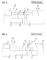
- FIG. 2 illustrating a typical on-board network topology of a vehicle with a trailer.
- the vehicle electrical system 24 has an interface 11 for connecting a trailer electrical system 20.
- An electrical energy store 9, a generator 23 (eg an alternator) and further electrical consumers 7, which form the load resistance of the vehicle electrical system 24, are connected to the vehicle electrical system 24 of the vehicle.
- the consumers 7 of the electrical system are in FIG. 2 as shown in the other figures as a load resistor.
- the consumers 7 of the electrical system 24 are connected in parallel via a supply line 12 and a grounded line 19 to the energy storage 9 and the generator 23.
- the on-board electrical system 20 in turn has one or more electrical consumers 22 and may optionally also have an electrical energy store 21.
- the onboard interface 20 can be electrically connected to the vehicle electrical system 24 via the interface 11.
- the interface 11 may further comprise terminals for further signal lines to control the individual consumers in the trailer. To simplify the illustration are in FIG. 2 these signal lines are not shown.
- FIG. 3 shows another known from the prior art vehicle electrical system 26 which is coupled to a trailer electrical system 20.
- the on-board electrical network 26 differs from the on-board electrical system of FIG. 2 essentially in that in the vehicle electrical system 26 a separate generator 25, z. B. in the form of another alternator, is provided, via which the trailer on-board network 20 is directly supplied.
- the electrical system trailer interface 11 is supplied directly by the additional generator 25 via a supply line 12a. This ensures a balanced charge balance.
- Vehicle wiring systems are also known from the prior art in which the vehicle electrical system is formed from a plurality of low-voltage sub-network, which are coupled to one another via a DC-DC converter.
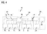
- FIG. 4 illustrates the topology of such a vehicle electrical system 41.
- the first low-voltage sub-network 43 in turn comprises an energy storage 9 and a plurality of electrical consumers 7, which form the load resistance of the electrical system 43. For example, a rated voltage of 24 volts may be applied to the first subnetwork.
- a second sub-board network 42 is provided on which, for example, a rated voltage of 48 volts is applied and in which a generator 10, for example a starter-generator, a second energy store 8 and optionally one or more consumers 6, preferably high-power consumers, are arranged.
- the second subnetwork 42 is coupled to the first subnetwork 43 via a DC / DC converter 44, so that the first subnetwork 43 can be supplied with power from the second subnetwork 42 via the DC / DC converter 44.
- a discrete connection 16 of the masses of the two subnetworks may be provided to form a mass connection. It is emphasized that this discrete connection to the mass coupling of the two subnetworks can also be effected by the DC-DC converter 44.
- a disadvantage of such an on-board network topology is the resulting increased load requirement on the DC-DC converter 44, the design of which must be adapted accordingly.
- a further disadvantage is that the additional load of the onboard electrical network 20 can be recognized only indirectly by increased power requirement from the subnetwork 43. It is also disadvantageous that no prioritization with respect to a power supply by the second subnetwork 42 from the vehicle on-board network 43 and the on-board electrical network 20 is possible unless additional switching elements are implemented in the system.
- the state of the onboard electrical system 20 for example, a state of charge of the battery 21 or the power requirement, only by additional introduction of other measuring points, such as voltage and current measuring points, are detected on the battery 21 of the trailer.
- the object of the invention is in particular to provide a vehicle electrical system with at least two coupled via a voltage transformer sub-board networks to which a trailer electrical system is connected and with a controlled power distribution and thus z. B. a prioritization between the vehicle and the on-board network is possible.
- the vehicle electrical system also has a first subnetwork in which a first nominal voltage is applied, and comprises a first energy store and a first load resistor formed by a plurality of consumers.
- the vehicle electrical system also has a second subnetwork, in which a second rated voltage is applied, and includes a generator and a second energy store.
- the first and the second subnetwork are coupled together via a first voltage converter.
- the second rated voltage is preferably higher than the first rated voltage. In the context of the invention, however, there is the possibility that the second rated voltage is the same as the first rated voltage, for example, to couple two 24V vehicle electrical systems with each other.
- a second voltage converter is further provided, wherein the interface for connecting the on-board electrical system via the second voltage converter is coupled to the second subnet.
- the interface for connecting the onboard electrical system is in particular an interface to Supplying the on-board electrical system with electrical energy, ie supplying the on-board electrical system with voltage and current.
- the voltage converter is designed in particular as a controlled or regulated voltage converter.
- the first voltage converter and the second voltage converter can be designed as a DC-DC converter (DC / DC converter).
- the on-board electrical network is thus supplied via the trailer interface via its own voltage converter from the part-board network having the generator.
- a conventional interface for connecting a trailer electrical system can be used with the vehicle on-board network topology according to the invention, so that conventional trailer systems can be connected and operated both with conventional vehicle on-board networks and with the vehicle electrical system according to the invention.
- On-board network topology is that disturbances, such as current ripple or voltage dips, can not spread from the on-board electrical system to the on-board electrical system and vice versa.
- the generator and the second energy store of the second subnetwork as well as the side of the first voltage converter connected to the second subnetwork and the side of the second voltage converter connected to the second subnetwork can be connected in parallel, so that, depending on the control of the voltage converter, optionally energy from the second subnetwork the first sub-network and / or the on-board network can be transferred.
- the first voltage converter and the second voltage converter are designed to convert an applied input voltage of the second subnet to the same output voltage in each case. Furthermore, the first voltage converter and the second voltage converter can be of identical construction.
- a particular advantage ofmaibordnetztopologie invention is thus that the DC-DC converter, which is used in a vehicle electrical system without trailer interface, for the operation of a corresponding electrical system with trailer interface does not need to be adjusted, but only an additional DC-DC converter of the same type can be used, so that a high proportion of identical parts is made possible.
- the first and the second subnet are ground-bound or ground-coupled.
- the second subnet is not designed as a low-voltage board subnet, but as a high-voltage network (rated voltage greater than 60V DC ) of a hybrid or electric vehicle and / or that the two subnets are galvanically separated from each other.
- a control device may be provided to control the operation of the first voltage converter and the second voltage converter.
- a control device is set up to control the first and second DC-DC converters such that energy is transferred from an energy store arranged in the onboard electrical network via the second subnetwork into the first subnetwork, if a state of charge of the energy accumulator in first subnet falls below a predetermined threshold.
- This can be a controlled or regulated energy transfer between the on-board electrical system and the two vehicle sub-board networks take place, so that, for example, a trailer can give the vehicle jump-start.
- control device can be set up to control the first and second DC voltage converters in such a way that energy is transferred from an energy store arranged in the vehicle electrical system via the second voltage converter into the trailer electrical system, if a state of charge of the energy accumulator in the onboard electrical system falls below a predetermined threshold, so that by means of the Vehicle on-board network of trailer energy storage can be specifically loaded and unloaded.
- the second voltage converter may comprise voltage and / or current measuring means on its output side facing the trailer interface.
- This offers the advantage that it is possible to use the (charge) state of the energy storage in the onboard electrical system and to control an energy transfer between the on-board electrical network and the second subnetwork depending on the detected state without the use of additional existing in the onboard electrical system monitoring stations.
- the means for voltage and / or current measurement can here directly on the output side be provided on the second voltage converter or in the line connection between the second voltage converter and the trailer interface.
- a further advantageous embodiment provides that the control device is set up during a stop phase of a start-stop operation of the vehicle to monitor the voltage applied to the interface for connecting the onboard electrical system voltage and to initiate a vehicle start, if the monitored voltage below a predetermined Threshold drops to avoid power failure in the trailer during extended periods of use.
- the generator in the second subsystem can be an electrical machine which is designed for generator operation or recuperation operation and for starting an internal combustion engine of the motor vehicle.
- the generator may be a crankshaft starter generator.
- the second energy store may be a supercapacitor memory or a Li-ion accumulator and may be configured to store electrical charge generated by the generator.
- the first voltage converter and the second voltage converter can be bidirectional, so that energy transfer from the vehicle electrical system to the on-board electrical system and energy transfer from the on-board electrical system to the vehicle electrical system are made possible.
- Another aspect relates to a bus, which is designed for coupling a passenger trailer and having an inventive electrical system, as disclosed herein.
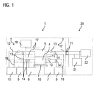
- FIG. 1 schematically illustrates an on-board network topology of a vehicle network from a bus with a passenger trailer.
- the trailer on-board network 20 is in conventional Carried out manner and includes an electrical energy storage and other electrical load 22, which form the load resistance of the electrical system 20 and which are supplied from the power storage 21 in the decoupled state of the trailer from the bus.
- the electrical system 1 of the bus comprises a first sub-network 3, in which a first rated voltage U1, z. B. 24 volts, is applied, and which comprises a first energy storage 9 and a load resistor 7.
- the load resistor 7 is formed by at least one, preferably by a plurality of consumers.
- the consumers in the first subnetwork 3 are preferably operated with a constant supply voltage.
- a sensor 14 for monitoring the voltage in the first subnetwork 3 and a sensor 13 for monitoring the current in the first subnetwork 3 are provided in the first subnetwork 3.
- a second subnet 2 is provided, in which a second mains voltage U2, z. B. 48 volts, is applied and in which a generator 10 is provided.
- a further energy store 8 is further provided, which is designed to store generated by the generator 10 electrical charge.
- the energy store 8 may be formed, for example, as a supercapacitor memory.
- one or more consumers 6 may optionally also be connected, which are preferably high current consumers.
- sensors 13, 14 are provided for current and voltage measurement.
- the solid black lines in FIG. 1 each denote the power lines by means of which the individual components of the vehicle electrical system are connected to each other.
- 12 denotes the electric supply line and the reference numeral 19, the earth-bound line.
- the electrical system 1 further comprises a DC-DC converter (DC / DC converter) 4, which bi-directionally couples the first subnetwork 3 to the second subnetwork 2 in a manner known per se.
- DC-DC converter DC / DC converter
- a second DC-DC converter 5 is provided, via which the second sub-network 2 can be connected to an interface 11 for connecting a trailer electrical system 20.
- the interface 11 is executed in a conventional manner and need not be described in detail. Via the interface 11, the trailer electrical system can be supplied with energy from the vehicle electrical system 1.
- the designated by the reference numeral 15 line is used for grounding the ground-based lines 19th
- the DC-DC converter 4 and 5 are designed to be identical.
- the generator 10, the second energy store 8 and the side of the first voltage converter connected to the second subnet 2 and the side of the second voltage converter 5 connected to the second subnet 2 are connected in parallel.
- the control unit 18 is configured, for example, to monitor the voltage applied to the output side of the second voltage converter 5 and the current flowing there by means of the sensors 13 and 14, wherein the output side is understood to be the side of the second DC-DC converter 5 facing the trailer interface 11. From the detected current and voltage measured values, the state of charge of the energy store 21 of the onboard electrical network 20 can be determined and monitored, if this is connected to the vehicle electrical system 1 via the interface 11.
- the control device 18 is further configured to control the first and second DC-DC converters 4, 5 such that energy is transferred from the energy storage 21 of the on-board electrical system 20 via the second subnetwork 2 into the first subnetwork 3, if a state of charge of the energy storage device 9 in the first subnetwork 3 is below falls a predetermined threshold. Further, during a stop phase of a start-stop operation of the vehicle, the control device is set up to monitor the voltage present at the interface 11 for connection of the onboard electrical network 20 and to initiate a vehicle start if the monitored voltage falls below a predetermined threshold value.
- connection 16 of the masses of the two subnetworks 2, 3, which allows a low-resistance connection between the two subnetworks to form the ground connection of the two subnetworks.
- the dashed line around the connection line 16 is intended to indicate that this line is optional, since such a connection can also be realized directly via the DC / DC converter.
Landscapes
- Engineering & Computer Science (AREA)
- Mechanical Engineering (AREA)
- Electric Propulsion And Braking For Vehicles (AREA)
Abstract
Description
- Die Erfindung betrifft ein Bordnetz für ein Kraftfahrzeug, insbesondere für ein Nutzfahrzeug, mit einer Schnittstelle zum Anschluss eines Anhängerbordnetzes.
- Niederspannungsbordnetze von Nutzfahrzeugen können eine Schnittstelle aufweisen, um das Bordnetz des Nutzfahrzeugs mit einem Bordnetz eines mit dem Nutzfahrzeug gekoppelten Anhängers zu verbinden. Beispielsweise können Stadtbusse mit einem sogenannten Personenanhänger verbunden werden, um die Kapazität der Linien in Stoßzeiten zu erhöhen. Derartige Personenanhänger verfügen über ein eigenes Anhängerbordnetz, um die verschiedenen elektrischen Verbraucher des Personenanhängers, wie beispielsweise Klima- und Heizanlage, Beleuchtungsanlagen etc., mit Strom zu versorgen.
- Dies ist beispielhaft anhand der
Figur 2 illustriert, die eine typische Bordnetztopologie eines Fahrzeugs mit Anhänger zeigt. Das Fahrzeugbordnetz 24 verfügt über eine Schnittstelle 11 zum Anschließen eines Anhängerbordnetzes 20. - An das Bordnetz 24 des Fahrzeugs sind ein elektrischer Energiespeicher 9, ein Generator 23 (z. B. eine Lichtmaschine) und weitere elektrische Verbraucher 7, die den Lastwiderstand des Bordnetzes 24 bilden, angeschlossenen. Die Verbraucher 7 des Bordnetzes werden in
Figur 2 wie auch in den anderen Figuren als ein Lastwiderstand dargestellt. Die Verbraucher 7 des Bordnetzes 24 sind über eine Versorgungsleitung 12 und eine massegebundene Leitung 19 mit dem Energiespeicher 9 und dem Generator 23 parallel verbunden. - Das Anhängerbordnetz 20 verfügt wiederum über einen oder mehrere elektrische Verbraucher 22 und kann optional auch über einen elektrischen Energiespeicher 21 verfügen. Über die Schnittstelle 11 kann somit das Anhängerbordnetz 20 mit dem Fahrzeugbordnetz 24 elektrisch verbunden werden. Neben den Anschlüssen für eine elektrische Versorgungsleitung 12 und eine massegebundene Leitung 19 kann die Schnittstelle 11 ferner Anschlüsse für weitere Signalleitungen aufweisen, um die einzelnen Verbraucher im Anhänger zu steuern. Zur Vereinfachung der Darstellung sind in
Figur 2 diese Signalleitungen nicht dargestellt. -
Figur 3 zeigt ein weiteres aus dem Stand der Technik bekanntes Fahrzeugbordnetz 26, das mit einem Anhängerbordnetz 20 koppelbar ist. Das Anhängerbordnetz 26 unterscheidet sich von dem Anhängerbordnetz derFigur 2 im Wesentlichen dadurch, dass im Fahrzeugbordnetz 26 ein separater Generator 25, z. B. in Form einer weiteren Lichtmaschine, vorgesehen ist, über den das Anhängerbordnetz 20 direkt versorgbar ist. Gemäß dieser Ausführungsvariante wird die Bordnetz-Anhängerschnittstelle 11 direkt über eine Versorgungsleitung 12a von dem zusätzlichen Generator 25 versorgt. Dadurch kann eine ausgeglichene Ladebilanz gewährleistet werden. - Aus dem Stand der Technik sind ferner Fahrzeugbordnetze bekannt, bei denen das Fahrzeugbordnetz aus mehreren Niederspannungs-Teilbordnetzen gebildet wird, die über einen Gleichspannungswandler miteinander gekoppelt werden.
Figur 4 illustriert die Topologie eines derartigen Fahrzeugbordnetzes 41. Das erste Niederspannungs-Teilnetz 43 umfasst wiederum einen Energiespeicher 9 und mehrere elektrische Verbraucher 7, die den Lastwiderstand des Bordnetzes 43 bilden. An dem ersten Teilnetz kann beispielsweise eine Nennspannung von 24 Volt anliegen. Ferner ist ein zweites Teilbordnetz 42 vorgesehen, an dem beispielsweise eine Nennspannung von 48 Volt anliegt und in dem ein Generator 10, beispielsweise ein Starter-Generator, ein zweiter Energiespeicher 8 und optional ein oder mehrere Verbraucher 6, vorzugsweise Hochleistungsverbraucher, angeordnet sind. Das zweite Teilnetz 42 ist über einen Gleichspannungswandler (DC/DC-Wandler) 44 mit dem ersten Teilnetz 43 gekoppelt, so dass das erste Teilnetz 43 mit Energie aus dem zweitem Teilnetz 42 über den Gleichspannungswandler 44 versorgt werden kann. - Ferner kann optional eine diskrete Verbindung 16 der Massen der beiden Teilnetze zur Ausbildung einer Massenverbindung vorgesehen sein. Es wird betont, dass diese diskrete Verbindung zur Massenkopplung der beiden Teilnetze auch durch den Gleichspannungswandler 44 erfolgen kann.
- Zur Ankopplung eines Anhängerbordnetzes wäre es nun denkbar, an dem Fahrzeugbordnetz 41 im ersten Teilnetz 43 wiederum die bekannte Schnittstelle 11 zur Ankopplung des Anhängerbordnetzes 20 vorzusehen, um das bekannte Bordnetz 41 für den Anhängerbetrieb zu erweitern.
- Nachteilig an einer derartigen Bordnetztopologie ist jedoch die dadurch resultierende erhöhte Lastanforderung an den Gleichspannungswandler 44, dessen Auslegung entsprechend angepasst werden muss. Ein weiterer Nachteil ist, dass die zusätzliche Last des Anhängerbordnetzes 20 nur indirekt durch erhöhten Leistungsbedarf aus dem Teilnetz 43 erkennbar ist. Es ist ferner nachteilig, dass keine Priorisierung in Bezug auf eine Energieversorgung durch das zweite Teilnetz 42 von dem Fahrzeugbordnetz 43 und dem Anhängerbordnetz 20 möglich ist, außer es werden zusätzliche Schaltelemente in das System implementiert. Schließlich kann der Zustand des Anhängerbordnetzes 20, beispielsweise ein Ladezustand der Batterie 21 oder der Leistungsbedarf, nur durch zusätzliches Einbringen weiterer Messstellen, beispielsweise Spannungs- und Strommessstellen, an der Batterie 21 des Anhängers erkannt werden.
- Es ist somit eine Aufgabe der Erfindung, ein verbessertes Bordnetz für ein Fahrzeug, insbesondere für ein Nutzfahrzeug bereitzustellen, das mit einem Anhängerbordnetz verbindbar ist und mit dem Nachteile herkömmlicher Techniken vermieden werden können. Die Aufgabe der Erfindung ist es insbesondere, ein Fahrzeugbordnetz mit wenigstens zwei über einen Spannungswandler gekoppelten Teilbordnetzen bereitzustellen, an dem ein Anhängerbordnetz anschließbar ist und mit dem eine kontrollierte Leistungsverteilung und damit z. B. eine Priorisierung zwischen dem Fahrzeug- und dem Anhängerbordnetz ermöglicht wird.
- Diese Aufgaben werden durch ein Bordnetz für ein Fahrzeug mit den Merkmalen des Hauptanspruchs gelöst. Vorteilhafte Ausführungen und Anwendungen der Erfindung sind Gegenstand der abhängigen Ansprüche und werden in der folgenden Beschreibung unter teilweiser Bezugnahme auf die Figuren näher erläutert.
- Das erfindungsgemäße Bordnetz für ein Kraftfahrzeug, insbesondere für ein Nutzfahrzeug, weist in Übereinstimmung mit dem Stand der Technik eine Schnittstelle zum Anschluss eines Anhängerbordnetzes auf. Das Bordnetz weist ferner ein erstes Teilnetz auf, in dem eine erste Nennspannung anliegt, und umfasst einen ersten Energiespeicher und einen ersten, durch mehrere Verbraucher gebildeten Lastwiderstand. Das Bordnetz weist ferner ein zweites Teilnetz auf, in dem eine zweite Nennspannung anliegt, und umfasst einen Generator und einen zweiten Energiespeicher. Das erste und das zweite Teilnetz sind über einen ersten Spannungswandler miteinander gekoppelt. Die zweite Nennspannung ist vorzugsweise höher als die erste Nennspannung. Im Rahmen der Erfindung besteht jedoch die Möglichkeit, dass die zweite Nennspannung die gleiche ist wie die erste Nennspannung, beispielsweise um zwei 24V-Bordnetze miteinander zu koppeln.
- Gemäß allgemeinen Gesichtspunkten der Erfindung ist ferner ein zweiter Spannungswandler vorgesehen, wobei die Schnittstelle zum Anschluss des Anhängerbordnetzes über den zweiten Spannungswandler mit dem zweiten Teilnetz gekoppelt ist. Bei der Schnittstelle zum Anschluss des Anhängerbordnetzes handelt es sich insbesondere um eine Schnittstelle zur Versorgung des Anhängerbordnetzes mit elektrischer Energie, d. h. zur Versorgung des Anhängerbordnetzes mit Spannung und Strom.
- Der Spannungswandler ist insbesondere als gesteuerter oder geregelter Spannungswandler ausgeführt. Der erste Spannungswandler und der zweite Spannungswandler können als Gleichspannungswandler (DC/DC-Wandler) ausgeführt sein.
- Erfindungsgemäß wird somit das Anhängerbordnetz über die Anhänger-Schnittstelle über einen eigenen Spannungswandler aus dem den Generator aufweisenden Teilbordnetz versorgt. Dadurch ergibt sich der Vorteil, dass durch den Einsatz des zusätzlichen zweiten Spannungswandlers eine kontrollierte Leistungsverteilung und damit beispielsweise eine Priorisierung zwischen dem Fahrzeug- und dem Anhängerbordnetz in Bezug auf eine Energieversorgung aus dem zweiten Teilnetz ermöglicht wird. Ferner kann eine herkömmliche Schnittstelle zum Anschluss eines Anhängerbordnetzes mit der erfindungsgemäßen Fahrzeugbordnetztopologie verwendet werden, so dass herkömmliche Anhängerbordnetze sowohl mit herkömmlichen Fahrzeugbordnetzen als auch mit dem erfindungsgemäßen Bordnetz verbindbar und betreibbar sind. Ein weiterer Vorteil der vorgeschlagenen. Bordnetztopologie ist, dass Störeinflüsse, beispielsweise Stromrippel oder Spannungseinbrüche, sich nicht vom Anhängerbordnetz auf das Fahrzeugbordnetz ausbreiten können und vice versa.
- Der Generator und der zweite Energiespeicher des zweiten Teilnetzes sowie die mit dem zweiten Teilnetz verbundene Seite des ersten Spannungswandlers und die mit dem zweiten Teilnetz verbundene Seite des zweiten Spannungswandlers können parallel geschaltet sein, so dass je nach Ansteuerung der Spannungswandler wahlweise Energie aus dem zweiten Teilnetz in das erste Teilnetz und/oder das Anhängerbordnetz transferiert werden kann.
- Gemäß einer bevorzugten Ausgestaltungsform der Erfindung sind der erste Spannungswandler und der zweite Spannungswandler ausgelegt, eine anliegende Eingangsspannung des zweiten Teilnetzes jeweils auf die gleiche Ausgangsspannung zu wandeln. Ferner können der erste Spannungswandler und der zweite Spannungswandler baugleich ausgeführt sein.
- Ein besonderer Vorzug der erfindungsgemäßen Fahrzeugbordnetztopologie liegt somit darin, dass der Gleichspannungswandler, der in einem Fahrzeugbordnetz ohne Anhängerschnittstelle eingesetzt wird, für den Betrieb eines entsprechenden Bordnetzes mit Anhängerschnittstelle nicht angepasst werden muss, sondern lediglich ein zusätzlicher Gleichspannungswandler gleicher Bauart eingesetzt werden kann, so dass ein hoher Anteil an Gleichteilen ermöglicht wird.
- Eine Möglichkeit der erfindungsgemäßen Realisierung sieht ferner vor, dass das erste und das zweite Teilnetz massegebunden bzw. massegekoppelt sind. Im Rahmen der Erfindung besteht jedoch auch die Möglichkeit, dass das zweite Teilnetz nicht als Niederspannungs-Bordteilnetz, sondern als Hochspannungsnetz (Nennspannung größer 60VDC) eines Hybridoder Elektrofahrzeugs ausgebildet ist und/oder dass die beiden Teilnetze galvanisch voneinander getrennt sind.
- Ferner kann eine Steuereinrichtung vorgesehen sein, um den Betrieb des ersten Spannungswandlers und des zweiten Spannungswandlers zu steuern. Eine Möglichkeit der erfindungsgemäßen Realisierung sieht hierbei insbesondere vor, dass eine derartige Steuereinrichtung eingerichtet ist, die ersten und zweiten Gleichspannungswandler derart anzusteuern, dass Energie von einem im Anhängerbordnetz angeordneten Energiespeicher über das zweite Teilnetz in das erste Teilnetz transferiert wird, falls ein Ladezustand des Energiespeichers im ersten Teilnetz unter einen vorbestimmten Schwellenwert fällt.
- Damit kann ein gesteuerter oder geregelter Energietransfer zwischen dem Anhängerbordnetz und den beiden Fahrzeug-Teilbordnetzen stattfinden, so dass beispielsweise ein Anhänger dem Fahrzeug Starthilfe gewähren kann.
- Ferner kann die Steuereinrichtung eingerichtet sein, die ersten und zweiten Gleichspannungswandler derart anzusteuern, dass Energie von einem im Fahrzeugbordnetz angeordneten Energiespeicher über den zweiten Spannungswandler in das Anhängerbordnetz transferiert wird, falls ein Ladezustand des Energiespeichers im Anhängerbordnetz unter einen vorbestimmten Schwellenwert fällt, so dass mittels des Fahrzeugbordnetzes der Anhänger-Energiespeicher gezielt geladen und entladen werden kann.
- Gemäß einer weiteren bevorzugten Ausführungsform kann der zweite Spannungswandler an seiner der Anhängerschnittstelle zugewandten Ausgangsseite Mittel zur Spannungs- und/oder Strommessung umfassen. Dies bietet den Vorteil, dass es ohne Einsatz zusätzlicher im Anhängerbordnetz vorhandener Messstellen möglich ist, den (Lade-)Zustand des Energiespeichers im Anhängerbordnetz zu erkennen und in Abhängigkeit von dem erfassten Zustand einen Energietransfer zwischen dem Anhängerbordnetz und dem zweiten Teilnetz zu steuern. Die Mittel zur Spannungs- und/oder Strommessung können hierbei direkt ausgangsseitig am zweiten Spannungswandler vorgesehen sein oder in der Leitungsverbindung zwischen dem zweiten Spannungswandler und der Anhängerschnittstelle.
- Eine weitere vorteilhafte Ausführungsvariante sieht vor, dass die Steuereinrichtung eingerichtet ist, während einer Stopp-Phase eines Start-Stopp-Betriebs des Fahrzeugs die an der Schnittstelle zum Anschluss des Anhängerbordnetzes anliegende Spannung zu überwachen und einen Fahrzeugstart einzuleiten, falls die überwachte Spannung unter einen vorbestimmten Schwellenwert fällt, um einen Ausfall der Stromversorgung im Anhänger während längerer Standzeiten zu vermeiden.
- Gemäß einem weiteren Aspekt der Erfindung kann der Generator im zweiten Teilnetz eine elektrische Maschine sein, die zum Generatorbetrieb bzw. Rekuperationsbetrieb und zum Starten eines Verbrennungsmotors des Kraftfahrzeugs ausgebildet ist. Beispielsweise kann der Generator ein Kurbelwellenstartergenerator sein. Der zweite Energiespeicher kann ein Superkondensatorspeicher oder ein Li-Ionen-Akkumulator sein und ausgebildet sein, von dem Generator erzeugte elektrische Ladung zu speichern. Der erste Spannungswandler und der zweite Spannungswandler können bidirektional ausgeführt sein, so dass ein Energietransfer vom Fahrzeugbordnetz in das Anhängerbordnetz und ein Energietransfer vom Anhängerbordnetz in das Fahrzeugbordnetz ermöglicht werden.
- Ein weiterer Aspekt betrifft einen Omnibus, der zur Ankopplung eines Personenanhängers ausgeführt ist und der ein erfindungsgemäßes Bordnetz, wie hierin offenbart, aufweist.
- Die zuvor beschriebenen bevorzugten Ausführungsformen und Merkmale der Erfindung sind beliebig miteinander kombinierbar. Weitere Einzelheiten und Vorteile der Erfindung werden im Folgenden unter Bezug auf die beigefügte
Figur 1 beschrieben. Es zeigen: - Figur 1
- eine Bordnetztopologie eines Nutzfahrzeugs mit einem Anhänger gemäß einer Ausführungsform der Erfindung;
- Figur 2
- eine aus dem Stand der Technik bekannte Bordnetztopologie;
- Figur 3
- eine aus dem Stand der Technik bekannte Bordnetztopologie; und
- Figur 4
- eine weitere Bordnetztopologie.
-
Figur 1 illustriert schematisch eine Bordnetztopologie eines Fahrzeugverbunds aus einem Omnibus mit einem Personenanhänger. Das Anhängerbordnetz 20 ist dabei in herkömmlicher Weise ausgeführt und umfasst einen elektrischen Energiespeicher und weitere elektrische Verbraucher 22, die den Lastwiderstand des Bordnetzes 20 bilden und die im abgekoppelten Zustand des Anhängers vom Omnibus von dem Energiespeicher 21 versorgbar sind. - Das Bordnetz 1 des Omnibusses umfasst ein erstes Teilnetz 3, in dem eine erste Nennspannung U1, z. B. 24 Volt, anliegt, und das einen ersten Energiespeicher 9 und einen Lastwiderstand 7 umfasst. Der Lastwiderstand 7 ist durch wenigstens einen, vorzugsweise durch mehrere Verbraucher gebildet. Die Verbraucher in dem ersten Teilnetz 3 werden vorzugsweise mit einer konstanten Versorgungsspannung betrieben. Ferner sind im ersten Teilnetz 3 ein Sensor 14 zur Überwachung der Spannung im ersten Teilnetz 3 und ein Sensor 13 zur Überwachung des Stromes im ersten Teilnetz 3 vorgesehen.
- Ferner ist ein zweites Teilnetz 2 vorgesehen, in dem eine zweite Netzspannung U2, z. B. 48 Volt, anliegt und in dem ein Generator 10 vorgesehen ist. Im zweiten Teilnetz 2 ist ferner ein weiterer Energiespeicher 8 vorgesehen, der ausgebildet ist, vom Generator 10 erzeugte elektrische Ladung zu speichern. Der Energiespeicher 8 kann beispielsweise als Superkondensatorspeicher ausgebildet sein. Im zweiten Teilnetz 2 können optional ferner ebenfalls ein oder mehrere Verbraucher 6 angeschlossen sein, die vorzugsweise Hochstromverbraucher sind. Im zweiten Teilnetz sind ebenfalls Sensoren 13, 14 zur Strom- und Spannungsmessung vorgesehen.
- Die durchgezogenen schwarzen Linien in
Figur 1 bezeichnen jeweils die Stromleitungen, mittels derer die einzelnen Komponenten der Bordnetze miteinander verbunden sind. Hierbei bezeichnet 12 die elektrische Versorgungsleitung und das Bezugszeichen 19 die massegebundene Leitung. Das Bordnetz 1 umfasst ferner einen Gleichspannungswandler (DC/DC-Wandler) 4, der das erste Teilnetz 3 mit dem zweiten Teilnetz 2 bidirektional in an sich bekannter Weise koppelt. - Ferner ist ein zweiter Gleichspannungswandler 5 vorgesehen, über den das zweite Teilnetz 2 mit einer Schnittstelle 11 zum Anschluss eines Anhängerbordnetzes 20 verbindbar ist.
- Die Schnittstelle 11 ist in an sich bekannter Weise ausgeführt und muss nicht näher beschrieben werden. Über die Schnittstelle 11 kann das Anhängerbordnetz mit Energie aus dem Fahrzeugbordnetz 1 versorgt werden. Die mit dem Bezugszeichen 15 gekennzeichnete Leitung dient zur Massekopplung der massegebundenen Leitungen 19.
- Im vorliegenden Ausführungsbeispiel sind die Gleichspannungswandler 4 und 5 baugleich ausgeführt. Der Generator 10, der zweite Energiespeicher 8 sowie die mit dem zweiten Teilnetz 2 verbundene Seite des ersten Spannungswandlers und die mit dem zweiten Teilnetz 2 verbundene Seite des zweiten Spannungswandlers 5 sind parallel geschaltet.
- Ein- und ausgangsseitig des zweiten Spannungswandlers 5 sind wiederum Strom- und Spannungssensoren 13, 14 vorgesehen. Die Steuerung des Bordnetzes 1 wird durch eine Steuerung 18 vorgenommen, die über entsprechende Signal- und Messleitungen 17 (sie sind in den Figuren zur Unterscheidung von stromführenden Leitungen gestrichelt dargestellt) mit den entsprechenden Komponenten des Bordnetzes 1 verbunden sind, insbesondere mit dem ersten Spannungswandler 4 und mit dem zweiten Spannungswandler 5. Zur Vereinfachung der Darstellung sind die übrigen Signalleitungen zu den anderen Komponenten des Bordnetzes in
Figur 1 nicht eingezeichnet. - Die Steuereinheit 18 ist beispielsweise ausgebildet, die ausgangsseitig am zweiten Spannungswandler 5 anliegende Spannung und den dort fließenden Strom mittels der Sensoren 13 und 14 zu überwachen, wobei unter Ausgangsseite die Seite des zweiten Gleichspannungswandlers 5 verstanden wird, die der Anhängerschnittstelle 11 zugewandt ist. Aus den erfassten Strom- und Spannungsmesswerten kann der Ladezustand des Energiespeichers 21 des Anhängerbordnetzes 20 ermittelt und überwacht werden, falls dieses am Fahrzeugbordnetz 1 über die Schnittstelle 11 angeschlossen ist.
- Die Steuereinrichtung 18 ist ferner eingerichtet, die ersten und zweiten Gleichspannungswandler 4, 5 derart anzusteuern, dass Energie vom Energiespeicher 21 des Anhängerbordnetzes 20 über das zweite Teilnetz 2 in das erste Teilnetz 3 transferiert wird, falls ein Ladezustand des Energiespeichers 9 im ersten Teilnetz 3 unter einen vorbestimmten Schwellenwert fällt. Ferner ist die Steuereinrichtung eingerichtet, während einer Stopp-Phase eines Start-Stopp-Betriebs des Fahrzeugs die an der Schnittstelle 11 zum Anschluss des Anhängerbordnetzes 20 anliegende Spannung zu überwachen und einen Fahrzeugstart einzuleiten, falls die überwachte Spannung unter einen vorbestimmten Schwellenwert fällt.
- Ferner ist in
Figur 1 eine diskrete Verbindung 16 der Massen der beiden Teilnetze 2, 3 dargestellt, die eine niederohmige Verbindung zwischen den beiden Teilnetzen zur Ausbildung der Masseverbindung der beiden Teilnetze ermöglicht. Die gestrichelte Linie um die Verbindungsleitung 16 soll anzeigen, dass diese Leitung optional ist, da eine derartige Verbindung auch direkt über den DC/DC-Wandler realisiert werden kann. - Obwohl die Erfindung unter Bezugnahme auf bestimmte Ausführungsbeispiele beschrieben worden ist, ist es für einen Fachmann ersichtlich, dass verschiedene Änderungen ausgeführt werden können und Äquivalente als Ersatz verwendet werden können, ohne den Bereich der Erfindung zu verlassen. Zusätzlich können viele Modifikationen ausgeführt werden, ohne den zugehörigen Bereich zu verlassen. Folglich soll die Erfindung nicht auf die offenbarten Ausführungsbeispiele begrenzt sein, sondern die Erfindung soll alle Ausführungsbeispiele umfassen, die in den Bereich der beigefügten Patentansprüche fallen.
-
- 1
- Fahrzeugbordnetz
- 2, 3
- Teilbordnetze des Fahrzeugbordnetzes
- 4, 5
- Spannungswandler
- 6
- Verbraucher im zweiten Teilnetz
- 7
- Verbraucher im ersten Teilnetz
- 8, 9
- Energiespeicher
- 10
- Generator
- 11
- Anhängerschnittstelle
- 12, 12a
- Versorgungsleitung
- 13
- Stromsensor
- 14
- Spannungssensor
- 15
- Masseleitung
- 16
- Verbindungsleitung der Massen
- 17
- Signalleitungen
- 18
- Steuereinrichtung
- 19
- Massegebundene Leitung
- 20
- Anhängerbordnetz
- 21
- Energiespeicher
- 22
- Verbraucher im Anhängerbordnetz
- 23
- Generator (Lichtmaschine)
- 24
- Fahrzeugbordnetz
- 25
- Generator (Lichtmaschine)
- 26, 41
- Fahrzeugbordnetz
- 42, 43
- Teilnetze des Fahrzeugbordnetzes
- 44
- Gleichspannungswandler
Claims (10)
- Bordnetz (1) für ein Kraftfahrzeug, insbesondere für ein Nutzfahrzeug, aufweisend
eine Schnittstelle (11) zum Anschluss eines Anhängerbordnetzes (20);
ein erstes Teilnetz (3), in dem eine erste Nennspannung anliegt, umfassend einen ersten Energiespeicher (9) und einen ersten, durch mehrere Verbraucher gebildeten Lastwiderstand (7);
ein zweites Teilnetz (2), in dem eine zweite Nennspannung anliegt, umfassend einen Generator (10) und einen zweiten Energiespeicher (8);
wobei das erste und das zweite Teilnetz (3, 2) über einen ersten Spannungswandler (4) miteinander gekoppelt sind; und
wobei die Schnittstelle (11) zum Anschluss des Anhängerbordnetzes (20) über einen zweiten Spannungswandler (5) mit dem zweiten Teilnetz (2) gekoppelt ist. - Bordnetz (1) nach Anspruch 1, dadurch gekennzeichnet, dass der Generator (10) und der zweite Energiespeicher (8) des zweiten Teilnetzes (2) sowie die mit dem zweiten Teilnetz (2) verbundene Seite des ersten Spannungswandlers (4) und die mit dem zweiten Teilnetz (2) verbundene Seite des zweiten Spannungswandlers (5) parallel geschaltet sind.
- Bordnetz (1) nach Anspruch 1 oder 2, dadurch gekennzeichnet, dass der erste Spannungswandler (4) und der zweite Spannungswandler (5) als Gleichspannungswandler ausgeführt sind.
- Bordnetz (1) nach einem der vorhergehenden Ansprüche, dadurch gekennzeichnet,(a) dass der erste Spannungswandler (4) und der zweite Spannungswandler (5) ausgeführt sind, eine anliegende Eingangsspannung des zweiten Teilnetzes (2) auf die gleiche Ausgangsspannung zu wandeln; und/oder(b) dass der erste Spannungswandler (4) und der zweite Spannungswandler (5) baugleich ausgeführt sind.
- Bordnetz (1) nach einem der vorhergehenden Ansprüche, dadurch gekennzeichnet, dass das erste und das zweite Teilnetz (2, 3) massegebunden sind.
- Bordnetz (1) nach einem der vorhergehenden Ansprüche, dadurch gekennzeichnet, dass der zweite Spannungswandler (5) an seiner der Anhängerschnittstelle (11) zugewandten Ausgangsseite Mittel zur Spannungs- und Strommessung umfasst.
- Bordnetz (1) nach einem der vorhergehenden Ansprüche, gekennzeichnet durch eine Steuereinrichtung (18), die eingerichtet ist, die ersten und zweiten Spannungswandler (4, 5) derart anzusteuern, dass Energie von einem im Anhängerbordnetz (20) angeordneten Energiespeicher (21) über das zweite Teilnetz (2) in das erste Teilnetz (3) transferiert wird, falls ein Ladezustand des Energiespeichers (9) im ersten Teilnetz (3) unter einen vorbestimmten Schwellenwert fällt.
- Bordnetz (1) nach einem der vorhergehenden Ansprüche, gekennzeichnet durch eine Steuereinrichtung (18), die eingerichtet ist, während einer Stopp-Phase eines Start-Stopp-Betriebs des Fahrzeugs die an der Schnittstelle (11) zum Anschluss des Anhängerbordnetzes (20) anliegende Spannung zu überwachen und einen Fahrzeugstart einzuleiten, falls die überwachte Spannung unter einen vorbestimmten Schwellenwert fällt.
- Bordnetz (1) nach einem der vorhergehenden Ansprüche, dadurch gekennzeichnet,(a) dass der Generator (10) eine elektrischen Maschine ist, die zum Generatorbetrieb bzw. Rekuperationsbetrieb und zum Starten eines Verbrennungsmotors des Kraftfahrzeugs ausgebildet ist; und/oder(b) dass der Generator (10) ein Kurbelwellenstartergenerator ist; und/oder(c) dass der zweite Energiespeicher (8), vorzugsweise ein Superkondensatorspeicher oder Li-Ionen-Akkumulator, ausgebildet ist, von dem Generator (10) erzeugte elektrische Ladung zu speichern; und/oder(d) dass der erste Spannungswandler (4) und der zweite Spannungswandler (5) bidirektional ausgeführt sind; und/oder(e) dass die zweite Nennspannung höher als die erste Nennspannung ist.
- Omnibus, der zur Ankupplung eines Personenanhängers ausgeführt ist, umfassend ein Bordnetz (1) nach einem der vorhergehenden Ansprüche.
Priority Applications (1)
| Application Number | Priority Date | Filing Date | Title |
|---|---|---|---|
| PL15001573T PL2985189T3 (pl) | 2014-08-14 | 2015-05-23 | Pokładowa sieć dla pojazdu mechanicznego, w szczególności pojazdu użytkowego |
Applications Claiming Priority (1)
| Application Number | Priority Date | Filing Date | Title |
|---|---|---|---|
| DE102014012154.2A DE102014012154A1 (de) | 2014-08-14 | 2014-08-14 | Bordnetz für ein Kraftfahrzeug, insbesondere für ein Nutzfahrzeug |
Publications (2)
| Publication Number | Publication Date |
|---|---|
| EP2985189A1 true EP2985189A1 (de) | 2016-02-17 |
| EP2985189B1 EP2985189B1 (de) | 2018-09-19 |
Family
ID=53365698
Family Applications (1)
| Application Number | Title | Priority Date | Filing Date |
|---|---|---|---|
| EP15001573.3A Active EP2985189B1 (de) | 2014-08-14 | 2015-05-23 | Bordnetz für ein kraftfahrzeug, insbesondere für ein nutzfahrzeug |
Country Status (3)
| Country | Link |
|---|---|
| EP (1) | EP2985189B1 (de) |
| DE (1) | DE102014012154A1 (de) |
| PL (1) | PL2985189T3 (de) |
Cited By (2)
| Publication number | Priority date | Publication date | Assignee | Title |
|---|---|---|---|---|
| CN110325395A (zh) * | 2017-02-27 | 2019-10-11 | 罗伯特·博世有限公司 | 用于运行机动车的设备和方法,机动车 |
| FR3106096A1 (fr) * | 2020-01-15 | 2021-07-16 | Psa Automobiles Sa | Dispositif de distribution d’énergie électrique tout type, pour un véhicule pouvant tracter une remorque |
Families Citing this family (7)
| Publication number | Priority date | Publication date | Assignee | Title |
|---|---|---|---|---|
| WO2015137222A1 (ja) | 2014-03-12 | 2015-09-17 | 三菱電機株式会社 | 電源システム |
| DE102016113464A1 (de) * | 2016-07-21 | 2018-01-25 | Dr. Ing. H.C. F. Porsche Aktiengesellschaft | Bordnetz für ein Fahrzeug |
| DE102019125383A1 (de) * | 2019-09-20 | 2021-03-25 | Audi Ag | Kraftfahrzeug mit zwei elektrischen Bordnetzen und einem elektrischen Fremdgeräteanschluss |
| DE102020112835A1 (de) | 2020-05-12 | 2021-11-18 | Bayerische Motoren Werke Aktiengesellschaft | Vorrichtung zum Versorgen eines Fahrzeugzugs mit elektrischer Energie |
| DE102020112836A1 (de) | 2020-05-12 | 2021-11-18 | Bayerische Motoren Werke Aktiengesellschaft | Vorrichtung zum Versorgen eines Anhängers mit elektrischer Energie |
| DE102021209044A1 (de) | 2021-08-18 | 2023-02-23 | Robert Bosch Gesellschaft mit beschränkter Haftung | Fahrzeug mit einem Hochspannungs- und einem Niederspannungssystem |
| DE102023003685A1 (de) | 2023-09-09 | 2025-03-13 | Mercedes-Benz Group AG | Verfahren und Vorrichtung zum elektrischen Verbinden eines Zugfahrzeuges mit einem Anhängerfahrzeug |
Citations (7)
| Publication number | Priority date | Publication date | Assignee | Title |
|---|---|---|---|---|
| US6344985B1 (en) * | 2000-12-05 | 2002-02-05 | Heart Transverter S.A. | Multiple port bi-directional power converter |
| WO2002066293A1 (de) * | 2001-02-16 | 2002-08-29 | Siemens Aktiengesellschaft | Kraftfahrzeug-bordnetz |
| US6507506B1 (en) * | 1999-06-09 | 2003-01-14 | Lear Automotive (Eeds) Spain, S. L. | Dual voltage electrical distribution system |
| EP1422803A1 (de) * | 2001-08-08 | 2004-05-26 | Lear Automotive (EEDS) Spain, S.L. | Elektrisches verteilersystem und verfahren für ein fahrzeug mit zwei netzwerken mit verschiedenen spannungspegeln |
| WO2009047103A1 (de) * | 2007-10-09 | 2009-04-16 | Continental Automotive Gmbh | Bordnetz und verfahren zum betreiben eines bordnetzes |
| WO2010002644A1 (en) * | 2008-07-02 | 2010-01-07 | Jerry Lee Wordsworth | Intelligent power management system |
| US8004242B1 (en) * | 2009-03-13 | 2011-08-23 | PH Ingenuities, LLC | System and method for managing distribution of vehicle power in a multiple battery system |
-
2014
- 2014-08-14 DE DE102014012154.2A patent/DE102014012154A1/de not_active Withdrawn
-
2015
- 2015-05-23 EP EP15001573.3A patent/EP2985189B1/de active Active
- 2015-05-23 PL PL15001573T patent/PL2985189T3/pl unknown
Patent Citations (7)
| Publication number | Priority date | Publication date | Assignee | Title |
|---|---|---|---|---|
| US6507506B1 (en) * | 1999-06-09 | 2003-01-14 | Lear Automotive (Eeds) Spain, S. L. | Dual voltage electrical distribution system |
| US6344985B1 (en) * | 2000-12-05 | 2002-02-05 | Heart Transverter S.A. | Multiple port bi-directional power converter |
| WO2002066293A1 (de) * | 2001-02-16 | 2002-08-29 | Siemens Aktiengesellschaft | Kraftfahrzeug-bordnetz |
| EP1422803A1 (de) * | 2001-08-08 | 2004-05-26 | Lear Automotive (EEDS) Spain, S.L. | Elektrisches verteilersystem und verfahren für ein fahrzeug mit zwei netzwerken mit verschiedenen spannungspegeln |
| WO2009047103A1 (de) * | 2007-10-09 | 2009-04-16 | Continental Automotive Gmbh | Bordnetz und verfahren zum betreiben eines bordnetzes |
| WO2010002644A1 (en) * | 2008-07-02 | 2010-01-07 | Jerry Lee Wordsworth | Intelligent power management system |
| US8004242B1 (en) * | 2009-03-13 | 2011-08-23 | PH Ingenuities, LLC | System and method for managing distribution of vehicle power in a multiple battery system |
Cited By (3)
| Publication number | Priority date | Publication date | Assignee | Title |
|---|---|---|---|---|
| CN110325395A (zh) * | 2017-02-27 | 2019-10-11 | 罗伯特·博世有限公司 | 用于运行机动车的设备和方法,机动车 |
| CN110325395B (zh) * | 2017-02-27 | 2023-03-14 | 罗伯特·博世有限公司 | 用于运行机动车的设备和方法,机动车 |
| FR3106096A1 (fr) * | 2020-01-15 | 2021-07-16 | Psa Automobiles Sa | Dispositif de distribution d’énergie électrique tout type, pour un véhicule pouvant tracter une remorque |
Also Published As
| Publication number | Publication date |
|---|---|
| DE102014012154A1 (de) | 2016-02-18 |
| EP2985189B1 (de) | 2018-09-19 |
| PL2985189T3 (pl) | 2019-02-28 |
Similar Documents
| Publication | Publication Date | Title |
|---|---|---|
| EP2985189B1 (de) | Bordnetz für ein kraftfahrzeug, insbesondere für ein nutzfahrzeug | |
| EP2501588B1 (de) | Bordnetz und verfahren und vorrichtung zum betreiben des bordnetzes | |
| EP2953227B1 (de) | Bordnetz für ein kraftfahrzeug | |
| EP3027472B1 (de) | Überspannungsschutz für ein mehrspannungsbordnetz | |
| EP2721704B1 (de) | Vorrichtung und verfahren zur verbindung von mehrspannungsbordnetzen | |
| EP3022433B1 (de) | Schalteranordnung in kraftfahrzeugbordnetz | |
| DE102017009355A1 (de) | Verfahren zum Betreiben von elektrischen Bordnetzen | |
| DE102013200763A1 (de) | System und verfahren für das fahrzeugenergiemanagement | |
| EP3067240B1 (de) | Verfahren zur spannungsversorgung eines bordnetzes eines kraftfahrzeugs | |
| DE102016122184A1 (de) | Fahrzeugstromverteilung, die Relais mit integriertem Spannungswandler aufweist | |
| DE102012215542A1 (de) | Schutz- und/oder Diagnoseeinrichtung für Mehrspannungsbordnetz, Mehrspannungsbordnetz und Verfahren zum Betrieb eines Mehrspannungsbordnetzes | |
| DE102013013369A1 (de) | Elektronische Sicherheitsabschaltung für Kraftfahrzeuge | |
| WO2020178233A1 (de) | Energienetz für ein kraftfahrzeug und verfahren zum betreiben eines energienetzes für ein kraftfahrzeug | |
| DE102012206932A1 (de) | Kraftfahrzeugbordnetz mit wenigstens zwei Teilnetzen | |
| DE102020007868A1 (de) | Verfahren zum Laden eines elektrischen Energiespeichers eines elektrisch angetriebenen Fahrzeugs unter Berücksichtigung einer elektrischen Isolation einer Ladestation, sowie Ladevorrichtung und Fahrzeug | |
| WO2019166148A1 (de) | Batterieanschluss für fahrzeugbordnetz | |
| DE102016200097A1 (de) | Bordnetz | |
| EP2840253A1 (de) | Bordnetz für ein Kraftfahrzeug und Verfahren zum Betrieb eines Bordnetzes | |
| EP3380855B1 (de) | Verfahren zur ermittlung einer leistungsfähigkeitsinformation einer batterie eines kraftfahrzeugseitigen, an einen gleichspannungswandler angebundenen bordnetzes und kraftfahrzeug | |
| DE102020127262A1 (de) | Erfassungseinrichtung, Erfassungsanordnung, Kraftfahrzeug und Verfahren zum Erfassen zumindest eines Zellparameters | |
| DE102016224618A1 (de) | Fahrzeug-Bordnetz mit hoher Verfügbarkeit | |
| DE102012209453A1 (de) | Kraftfahrzeugbordnetz mit einer elektrischen Maschine und wenigstens zwei Energiespeichern mit unterschiedlichen Ladespannungen sowie Verfahren zum Betreiben desselben | |
| WO2013107560A1 (de) | Bordnetz mit gleichspannungswandler, steuereinrichtung und zugehöriges betriebsverfahren | |
| WO2017220233A1 (de) | Kraftfahrzeugbordnetz mit wenigstens zwei energiespeichern, verfahren zum betreiben eines kraftfahrzeugbordnetzes und mittel zu dessen implementierung | |
| DE102013002080A1 (de) | Elektrische Konvertierungseinrichtung für ein Elektro- oder Hybridfahrzeug |
Legal Events
| Date | Code | Title | Description |
|---|---|---|---|
| PUAI | Public reference made under article 153(3) epc to a published international application that has entered the european phase |
Free format text: ORIGINAL CODE: 0009012 |
|
| AK | Designated contracting states |
Kind code of ref document: A1 Designated state(s): AL AT BE BG CH CY CZ DE DK EE ES FI FR GB GR HR HU IE IS IT LI LT LU LV MC MK MT NL NO PL PT RO RS SE SI SK SM TR |
|
| AX | Request for extension of the european patent |
Extension state: BA ME |
|
| 17P | Request for examination filed |
Effective date: 20160808 |
|
| RIC1 | Information provided on ipc code assigned before grant |
Ipc: B60R 16/03 20060101AFI20180308BHEP |
|
| GRAP | Despatch of communication of intention to grant a patent |
Free format text: ORIGINAL CODE: EPIDOSNIGR1 |
|
| STAA | Information on the status of an ep patent application or granted ep patent |
Free format text: STATUS: GRANT OF PATENT IS INTENDED |
|
| INTG | Intention to grant announced |
Effective date: 20180420 |
|
| GRAS | Grant fee paid |
Free format text: ORIGINAL CODE: EPIDOSNIGR3 |
|
| GRAA | (expected) grant |
Free format text: ORIGINAL CODE: 0009210 |
|
| STAA | Information on the status of an ep patent application or granted ep patent |
Free format text: STATUS: THE PATENT HAS BEEN GRANTED |
|
| RIN1 | Information on inventor provided before grant (corrected) |
Inventor name: KRAFT, FERRY Inventor name: KIGIN, ERDOGAN Inventor name: FISCHER, DETLEF Inventor name: PFAU, STEFAN |
|
| AK | Designated contracting states |
Kind code of ref document: B1 Designated state(s): AL AT BE BG CH CY CZ DE DK EE ES FI FR GB GR HR HU IE IS IT LI LT LU LV MC MK MT NL NO PL PT RO RS SE SI SK SM TR |
|
| REG | Reference to a national code |
Ref country code: GB Ref legal event code: FG4D Free format text: NOT ENGLISH |
|
| REG | Reference to a national code |
Ref country code: CH Ref legal event code: EP |
|
| REG | Reference to a national code |
Ref country code: AT Ref legal event code: REF Ref document number: 1042890 Country of ref document: AT Kind code of ref document: T Effective date: 20181015 |
|
| REG | Reference to a national code |
Ref country code: IE Ref legal event code: FG4D Free format text: LANGUAGE OF EP DOCUMENT: GERMAN |
|
| REG | Reference to a national code |
Ref country code: DE Ref legal event code: R096 Ref document number: 502015005910 Country of ref document: DE |
|
| REG | Reference to a national code |
Ref country code: NL Ref legal event code: FP |
|
| REG | Reference to a national code |
Ref country code: SE Ref legal event code: TRGR |
|
| PG25 | Lapsed in a contracting state [announced via postgrant information from national office to epo] |
Ref country code: RS Free format text: LAPSE BECAUSE OF FAILURE TO SUBMIT A TRANSLATION OF THE DESCRIPTION OR TO PAY THE FEE WITHIN THE PRESCRIBED TIME-LIMIT Effective date: 20180919 Ref country code: NO Free format text: LAPSE BECAUSE OF FAILURE TO SUBMIT A TRANSLATION OF THE DESCRIPTION OR TO PAY THE FEE WITHIN THE PRESCRIBED TIME-LIMIT Effective date: 20181219 Ref country code: LT Free format text: LAPSE BECAUSE OF FAILURE TO SUBMIT A TRANSLATION OF THE DESCRIPTION OR TO PAY THE FEE WITHIN THE PRESCRIBED TIME-LIMIT Effective date: 20180919 Ref country code: GR Free format text: LAPSE BECAUSE OF FAILURE TO SUBMIT A TRANSLATION OF THE DESCRIPTION OR TO PAY THE FEE WITHIN THE PRESCRIBED TIME-LIMIT Effective date: 20181220 Ref country code: FI Free format text: LAPSE BECAUSE OF FAILURE TO SUBMIT A TRANSLATION OF THE DESCRIPTION OR TO PAY THE FEE WITHIN THE PRESCRIBED TIME-LIMIT Effective date: 20180919 Ref country code: BG Free format text: LAPSE BECAUSE OF FAILURE TO SUBMIT A TRANSLATION OF THE DESCRIPTION OR TO PAY THE FEE WITHIN THE PRESCRIBED TIME-LIMIT Effective date: 20181219 |
|
| REG | Reference to a national code |
Ref country code: LT Ref legal event code: MG4D |
|
| PG25 | Lapsed in a contracting state [announced via postgrant information from national office to epo] |
Ref country code: LV Free format text: LAPSE BECAUSE OF FAILURE TO SUBMIT A TRANSLATION OF THE DESCRIPTION OR TO PAY THE FEE WITHIN THE PRESCRIBED TIME-LIMIT Effective date: 20180919 Ref country code: AL Free format text: LAPSE BECAUSE OF FAILURE TO SUBMIT A TRANSLATION OF THE DESCRIPTION OR TO PAY THE FEE WITHIN THE PRESCRIBED TIME-LIMIT Effective date: 20180919 Ref country code: HR Free format text: LAPSE BECAUSE OF FAILURE TO SUBMIT A TRANSLATION OF THE DESCRIPTION OR TO PAY THE FEE WITHIN THE PRESCRIBED TIME-LIMIT Effective date: 20180919 |
|
| PG25 | Lapsed in a contracting state [announced via postgrant information from national office to epo] |
Ref country code: ES Free format text: LAPSE BECAUSE OF FAILURE TO SUBMIT A TRANSLATION OF THE DESCRIPTION OR TO PAY THE FEE WITHIN THE PRESCRIBED TIME-LIMIT Effective date: 20180919 Ref country code: IS Free format text: LAPSE BECAUSE OF FAILURE TO SUBMIT A TRANSLATION OF THE DESCRIPTION OR TO PAY THE FEE WITHIN THE PRESCRIBED TIME-LIMIT Effective date: 20190119 Ref country code: RO Free format text: LAPSE BECAUSE OF FAILURE TO SUBMIT A TRANSLATION OF THE DESCRIPTION OR TO PAY THE FEE WITHIN THE PRESCRIBED TIME-LIMIT Effective date: 20180919 Ref country code: CZ Free format text: LAPSE BECAUSE OF FAILURE TO SUBMIT A TRANSLATION OF THE DESCRIPTION OR TO PAY THE FEE WITHIN THE PRESCRIBED TIME-LIMIT Effective date: 20180919 Ref country code: EE Free format text: LAPSE BECAUSE OF FAILURE TO SUBMIT A TRANSLATION OF THE DESCRIPTION OR TO PAY THE FEE WITHIN THE PRESCRIBED TIME-LIMIT Effective date: 20180919 |
|
| PG25 | Lapsed in a contracting state [announced via postgrant information from national office to epo] |
Ref country code: SK Free format text: LAPSE BECAUSE OF FAILURE TO SUBMIT A TRANSLATION OF THE DESCRIPTION OR TO PAY THE FEE WITHIN THE PRESCRIBED TIME-LIMIT Effective date: 20180919 Ref country code: SM Free format text: LAPSE BECAUSE OF FAILURE TO SUBMIT A TRANSLATION OF THE DESCRIPTION OR TO PAY THE FEE WITHIN THE PRESCRIBED TIME-LIMIT Effective date: 20180919 Ref country code: PT Free format text: LAPSE BECAUSE OF FAILURE TO SUBMIT A TRANSLATION OF THE DESCRIPTION OR TO PAY THE FEE WITHIN THE PRESCRIBED TIME-LIMIT Effective date: 20190119 |
|
| REG | Reference to a national code |
Ref country code: DE Ref legal event code: R097 Ref document number: 502015005910 Country of ref document: DE |
|
| RAP2 | Party data changed (patent owner data changed or rights of a patent transferred) |
Owner name: MAN TRUCK & BUS SE |
|
| PLBE | No opposition filed within time limit |
Free format text: ORIGINAL CODE: 0009261 |
|
| STAA | Information on the status of an ep patent application or granted ep patent |
Free format text: STATUS: NO OPPOSITION FILED WITHIN TIME LIMIT |
|
| PG25 | Lapsed in a contracting state [announced via postgrant information from national office to epo] |
Ref country code: DK Free format text: LAPSE BECAUSE OF FAILURE TO SUBMIT A TRANSLATION OF THE DESCRIPTION OR TO PAY THE FEE WITHIN THE PRESCRIBED TIME-LIMIT Effective date: 20180919 |
|
| 26N | No opposition filed |
Effective date: 20190620 |
|
| REG | Reference to a national code |
Ref country code: DE Ref legal event code: R081 Ref document number: 502015005910 Country of ref document: DE Owner name: MAN TRUCK & BUS SE, DE Free format text: FORMER OWNER: MAN TRUCK & BUS AG, 80995 MUENCHEN, DE |
|
| PG25 | Lapsed in a contracting state [announced via postgrant information from national office to epo] |
Ref country code: SI Free format text: LAPSE BECAUSE OF FAILURE TO SUBMIT A TRANSLATION OF THE DESCRIPTION OR TO PAY THE FEE WITHIN THE PRESCRIBED TIME-LIMIT Effective date: 20180919 |
|
| REG | Reference to a national code |
Ref country code: CH Ref legal event code: PL |
|
| GBPC | Gb: european patent ceased through non-payment of renewal fee |
Effective date: 20190523 |
|
| PG25 | Lapsed in a contracting state [announced via postgrant information from national office to epo] |
Ref country code: LI Free format text: LAPSE BECAUSE OF NON-PAYMENT OF DUE FEES Effective date: 20190531 Ref country code: MC Free format text: LAPSE BECAUSE OF FAILURE TO SUBMIT A TRANSLATION OF THE DESCRIPTION OR TO PAY THE FEE WITHIN THE PRESCRIBED TIME-LIMIT Effective date: 20180919 Ref country code: CH Free format text: LAPSE BECAUSE OF NON-PAYMENT OF DUE FEES Effective date: 20190531 |
|
| REG | Reference to a national code |
Ref country code: BE Ref legal event code: MM Effective date: 20190531 |
|
| PG25 | Lapsed in a contracting state [announced via postgrant information from national office to epo] |
Ref country code: LU Free format text: LAPSE BECAUSE OF NON-PAYMENT OF DUE FEES Effective date: 20190523 |
|
| PG25 | Lapsed in a contracting state [announced via postgrant information from national office to epo] |
Ref country code: IE Free format text: LAPSE BECAUSE OF NON-PAYMENT OF DUE FEES Effective date: 20190523 Ref country code: GB Free format text: LAPSE BECAUSE OF NON-PAYMENT OF DUE FEES Effective date: 20190523 |
|
| PG25 | Lapsed in a contracting state [announced via postgrant information from national office to epo] |
Ref country code: BE Free format text: LAPSE BECAUSE OF NON-PAYMENT OF DUE FEES Effective date: 20190531 |
|
| PG25 | Lapsed in a contracting state [announced via postgrant information from national office to epo] |
Ref country code: CY Free format text: LAPSE BECAUSE OF FAILURE TO SUBMIT A TRANSLATION OF THE DESCRIPTION OR TO PAY THE FEE WITHIN THE PRESCRIBED TIME-LIMIT Effective date: 20180919 |
|
| REG | Reference to a national code |
Ref country code: AT Ref legal event code: MM01 Ref document number: 1042890 Country of ref document: AT Kind code of ref document: T Effective date: 20200523 |
|
| PG25 | Lapsed in a contracting state [announced via postgrant information from national office to epo] |
Ref country code: MT Free format text: LAPSE BECAUSE OF FAILURE TO SUBMIT A TRANSLATION OF THE DESCRIPTION OR TO PAY THE FEE WITHIN THE PRESCRIBED TIME-LIMIT Effective date: 20180919 |
|
| PG25 | Lapsed in a contracting state [announced via postgrant information from national office to epo] |
Ref country code: AT Free format text: LAPSE BECAUSE OF NON-PAYMENT OF DUE FEES Effective date: 20200523 |
|
| PG25 | Lapsed in a contracting state [announced via postgrant information from national office to epo] |
Ref country code: MK Free format text: LAPSE BECAUSE OF FAILURE TO SUBMIT A TRANSLATION OF THE DESCRIPTION OR TO PAY THE FEE WITHIN THE PRESCRIBED TIME-LIMIT Effective date: 20180919 |
|
| PGFP | Annual fee paid to national office [announced via postgrant information from national office to epo] |
Ref country code: NL Payment date: 20250526 Year of fee payment: 11 |
|
| PGFP | Annual fee paid to national office [announced via postgrant information from national office to epo] |
Ref country code: PL Payment date: 20250514 Year of fee payment: 11 Ref country code: DE Payment date: 20250528 Year of fee payment: 11 |
|
| PGFP | Annual fee paid to national office [announced via postgrant information from national office to epo] |
Ref country code: HU Payment date: 20250530 Year of fee payment: 11 |
|
| PGFP | Annual fee paid to national office [announced via postgrant information from national office to epo] |
Ref country code: IT Payment date: 20250522 Year of fee payment: 11 |
|
| PGFP | Annual fee paid to national office [announced via postgrant information from national office to epo] |
Ref country code: FR Payment date: 20250526 Year of fee payment: 11 |
|
| PGFP | Annual fee paid to national office [announced via postgrant information from national office to epo] |
Ref country code: TR Payment date: 20250512 Year of fee payment: 11 |
|
| PGFP | Annual fee paid to national office [announced via postgrant information from national office to epo] |
Ref country code: SE Payment date: 20250526 Year of fee payment: 11 |