EP2984520B1 - Optical filtering for cameras - Google Patents
Optical filtering for cameras Download PDFInfo
- Publication number
- EP2984520B1 EP2984520B1 EP14778580.2A EP14778580A EP2984520B1 EP 2984520 B1 EP2984520 B1 EP 2984520B1 EP 14778580 A EP14778580 A EP 14778580A EP 2984520 B1 EP2984520 B1 EP 2984520B1
- Authority
- EP
- European Patent Office
- Prior art keywords
- optical filter
- level
- image data
- camera
- processor
- Prior art date
- Legal status (The legal status is an assumption and is not a legal conclusion. Google has not performed a legal analysis and makes no representation as to the accuracy of the status listed.)
- Active
Links
Images






Classifications
-
- H—ELECTRICITY
- H04—ELECTRIC COMMUNICATION TECHNIQUE
- H04N—PICTORIAL COMMUNICATION, e.g. TELEVISION
- H04N23/00—Cameras or camera modules comprising electronic image sensors; Control thereof
- H04N23/70—Circuitry for compensating brightness variation in the scene
- H04N23/75—Circuitry for compensating brightness variation in the scene by influencing optical camera components
-
- G—PHYSICS
- G03—PHOTOGRAPHY; CINEMATOGRAPHY; ANALOGOUS TECHNIQUES USING WAVES OTHER THAN OPTICAL WAVES; ELECTROGRAPHY; HOLOGRAPHY
- G03B—APPARATUS OR ARRANGEMENTS FOR TAKING PHOTOGRAPHS OR FOR PROJECTING OR VIEWING THEM; APPARATUS OR ARRANGEMENTS EMPLOYING ANALOGOUS TECHNIQUES USING WAVES OTHER THAN OPTICAL WAVES; ACCESSORIES THEREFOR
- G03B11/00—Filters or other obturators specially adapted for photographic purposes
-
- G—PHYSICS
- G03—PHOTOGRAPHY; CINEMATOGRAPHY; ANALOGOUS TECHNIQUES USING WAVES OTHER THAN OPTICAL WAVES; ELECTROGRAPHY; HOLOGRAPHY
- G03B—APPARATUS OR ARRANGEMENTS FOR TAKING PHOTOGRAPHS OR FOR PROJECTING OR VIEWING THEM; APPARATUS OR ARRANGEMENTS EMPLOYING ANALOGOUS TECHNIQUES USING WAVES OTHER THAN OPTICAL WAVES; ACCESSORIES THEREFOR
- G03B7/00—Control of exposure by setting shutters, diaphragms or filters, separately or conjointly
-
- H—ELECTRICITY
- H04—ELECTRIC COMMUNICATION TECHNIQUE
- H04N—PICTORIAL COMMUNICATION, e.g. TELEVISION
- H04N23/00—Cameras or camera modules comprising electronic image sensors; Control thereof
- H04N23/50—Constructional details
- H04N23/51—Housings
-
- H—ELECTRICITY
- H04—ELECTRIC COMMUNICATION TECHNIQUE
- H04N—PICTORIAL COMMUNICATION, e.g. TELEVISION
- H04N23/00—Cameras or camera modules comprising electronic image sensors; Control thereof
- H04N23/50—Constructional details
- H04N23/54—Mounting of pick-up tubes, electronic image sensors, deviation or focusing coils
-
- H—ELECTRICITY
- H04—ELECTRIC COMMUNICATION TECHNIQUE
- H04N—PICTORIAL COMMUNICATION, e.g. TELEVISION
- H04N23/00—Cameras or camera modules comprising electronic image sensors; Control thereof
- H04N23/50—Constructional details
- H04N23/55—Optical parts specially adapted for electronic image sensors; Mounting thereof
-
- H—ELECTRICITY
- H04—ELECTRIC COMMUNICATION TECHNIQUE
- H04N—PICTORIAL COMMUNICATION, e.g. TELEVISION
- H04N23/00—Cameras or camera modules comprising electronic image sensors; Control thereof
- H04N23/70—Circuitry for compensating brightness variation in the scene
- H04N23/73—Circuitry for compensating brightness variation in the scene by influencing the exposure time
-
- G—PHYSICS
- G02—OPTICS
- G02B—OPTICAL ELEMENTS, SYSTEMS OR APPARATUS
- G02B2207/00—Coding scheme for general features or characteristics of optical elements and systems of subclass G02B, but not including elements and systems which would be classified in G02B6/00 and subgroups
- G02B2207/129—Coded aperture imaging
Definitions
- Motion picture film cameras expose film by allowing light to pass through a lens opening and then through a shutter aperture.
- a shutter rotates at a speed synchronous with that of passing film frames.
- Digital motion picture cameras expose an image sensor by electronically controlling an exposure time for each frame to achieve a similar effect.
- US 2012/062845 provides a system for and method of frequency prefiltering comprising a camera shutter capable of continuously variable illumination during a single exposure of the sensor, as well as a postfilter comprising a digital finite impulse response convolutional filter.
- a camera can include a camera housing, an image sensor within the camera housing, and a processor in communication with the image sensor.
- the image sensor can convert light entering the camera housing into digital image data.
- the light can pass through a variable opacity optical filter situated in the optical path prior to arriving at the image sensor.
- the processor can set operation settings for the optical filter at least in part according to a user input, generate control information that causes an opacity level of the optical filter to be controlled over an exposure period of each of a plurality of video image frames in accordance with the operation settings for the optical filter.
- the processor When the operation settings for the optical filter indicate a temporal filtering mode, the processor is configured to generate the control information so that over the exposure period the optical filter gradually increases its transmissivity to a first level and subsequently gradually decreases the transmissivity from the first level before the end of the exposure period.
- the processor When the operation settings for the optical filter indicate a global shutter mode, the processor is configured to generate the control information so that over the exposure period the optical filter maintains a second level of transmissivity, abruptly increases transmissivity from the second level to a third level, maintains the third level of transmissivity, and abruptly decreases transmissivity from the third level.
- the processor can modify values of the digital image data based at least on the operation settings for the optical filter to address color shifting in the digital image data introduced by the optical filter.
- the processor is configured to modify the values of the digital image data by reducing the values of the digital image data a greater amount when the operation settings for the optical filter indicate the temporal filtering mode than when the operation settings for the optical filter indicate the global shuttering
- the operation settings for the optical filter can include a neutral density setting, and the processor can maintain the opacity level of the optical filter over the exposure period at an opacity level corresponding to the neutral density setting.
- the processor can modify the values of the digital image data by applying a matrix to the digital image data to at least counteract an effect of the optical filter on the digital image data.
- the processor can modify the values of the digital image data by applying the matrix to the digital image data to at least perform colorimetry calibration associated with one or more components other than the optical filter.
- the digital image data can include first, second, and third colors, and the processor can modify values for the first color based at least on the operation settings for the optical filter.
- the first color can include blue image data.
- the processor can modify the values of the first color by reducing the values for the first color a greater amount when an opacity level of the optical filter is at a first level than when the opacity level of the optical filter is at a second level different from the first level.
- the processor can modify the values of the digital image data so as to counteract a color shift caused by the optical filter.
- the processor can modify the values of the digital image data so as to counteract a white point shift in the digital image data caused by the optical filter.
- the processor can modify the values of the digital image data so as to counteract a white point shift in the digital image data caused by the optical filter.
- the processor can modify the values of the digital image data in accordance with a first function to counteract a white point shift in the digital image data caused by the optical filter and in accordance with a second function to counteract a color shift caused by the optical filter, and the processor can modify the values of the digital image data in accordance with the first function before modifying the values of the digital image data in accordance with the second function.
- the optical filter can be a part of a lens mount releasably connected to the camera housing.
- the processor can modify the values of the digital image data based at least on a shutter angle associated with the optical filter.
- the processor can set the operation settings for the optical filter at least in part according to a user input.
- the optical filter can be included in a lens mount removably attached to the camera housing.
- the camera can further include the optical filter, which can be contained within the camera housing.
- the optical filter can include a liquid crystal panel.
- the processor can generate the control information so as to operate the optical filter in at least three different modes corresponding to: (i) the temporal filtering mode in which the optical filter gradually increases its transmissivity to a first level, and subsequently gradually decreases the transmissivity from the first level before the end of the exposure period; (ii) the global shutter mode wherein the optical filter (a) maintains a first level of transmissivity, (b) abruptly increases transmissivity from the first level to a second level, (c) maintains the second level of transmissivity, and (d) abruptly decreases transmissivity from the second level; and (iii) a neutral density mode wherein the opacity is maintained at a constant value over the exposure period.
- a method of operating a camera includes: setting operation settings for a variable opacity optical filter (102) at least in part according to a user input; controlling, with a processor, an opacity level of the optical filter over an exposure period of each of a plurality of video image frames in accordance with the operation settings for the optical filter; converting, with an image sensor within a camera housing, light entering the camera housing into digital image data, the light passing through the optical filter prior to arriving at the image sensor; and wherein when the operation settings for the optical filter indicate a temporal filtering mode, the processor generating the control information so that over the exposure period the optical filter gradually increases its transmissivity to a first level and subsequently gradually decreases the transmissivity from the first level before the end of the exposure period, wherein when the operation settings for the optical filter indicates a global shutter mode, the processor generating the control information so that over the exposure period the optical filter maintains a second level of transmissivity, abruptly increases transmissivity from the second level to a third level, maintains the third
- the operation settings for the optical filter can include a neutral density setting, and the method can further include maintaining an opacity level of the optical filter over the exposure period at a level that corresponds to the neutral density setting.
- the modifying can include applying a matrix to the digital image data to at least counteract an effect of the optical filter on the digital image data.
- the modifying can include modifying the digital image data in accordance with a first function to counteract a white point shift in the digital image data caused by the optical filter before modifying the digital image data in accordance with a second function to counteract a color shift caused by the optical filter.
- optical filtering e.g., using one or more variable-opacity optical filters.
- the optical filters can be integrated with an existing camera component, such as a lens mount or camera body.
- the filters can operate in one or more of multiple modes, including modes for neutral density filtering, temporal filtering, or global shuttering.
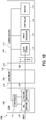
- Figs. 1A-C illustrate various configurations of camera systems 100a, 100b including one or more optical filters 102.
- the camera systems 100a, 100b can be used to detect and process video image data.
- the camera system 100a of Fig. 1A includes a camera housing 104, a lens mount 106, and a lens 108.
- the camera housing 104 is provided with a lens mount interface 110 for releasable attachment with a corresponding interface 112 of the lens mount 106.
- the lens mount 106 further includes a lens interface 114 configured to accept and support the lens 108.
- the camera system 100a may generally incorporate components or functionality of, or be otherwise similar to or the same as any of the cameras described in U.S. Patent No. 8,237,830, issued on August 7, 2012 , titled “VIDEO CAMERA” or U.S. Patent No. 8,525,925, issued on September 3, 2013 , titled “MODULAR DIGITAL CAMERA,”.
- the camera system 100a includes at least one image sensor 114, at least one memory 113, at least one controller 116, at least one image processor 119 within the camera housing 104.
- the controller 116 generally manages operation of the image sensor 114, and can be in communication with a lens mount controller 118 of the lens mount 106 so as to synchronize operation of the optical filter 102 and image sensor 114.
- the lens mount controller 118 in certain embodiments, communicates and controls operation of the lens 108, e.g., at the direction of the controller 116.
- the image processor 119 generally processes the image data output from the image sensor 114. Before or after the image processor 119 processes the image data, the image data can be stored to the memory 113.
- the image processor 119 can format the data stream from the image sensor 114 in any known manner and can separate green, red, and blue image data into separate data compilations. For example, the image processor 119 can separate the red data into one data element, the blue data into one blue data element, and the green data into one green data element.
- the controller 116 and image processor 119 are shown as a separate processor and controller in the illustrated embodiment of Fig. 1 , the controller 116 and image processor 119 can be implemented using the same processor or controller in other embodiments.
- the camera system 100a also includes one or more of a compression module (not shown) for compressing image data, display (not shown) for displaying images to a user of the camera system 100a, and display controller (not shown) for controlling the images shown by the display.
- the one or more of the compression module, display, and display controller can be in communication with the image sensor 114, the memory 113, the controller 116, and the image processor 119.
- the compression module can be incorporated within the image processor 119, for example.
- the image sensor 114 can be any type of image sensing device, including, for example, but without limitation, CCD, CMOS, vertically-stacked CMOS devices such as the Foveon® sensor, or a multi-sensor array using a prism to divide light between the sensors.
- the image sensor 114 can provide variable resolution by selectively outputting a predetermined portion of the image sensor 114, and the image sensor 114 and image processor 119 can allow a user to identify the resolution of the image data output.
- the sensor 114 can include a Bayer pattern filter. As such, the sensor 114, by way of its chipset (not shown) may output data representing magnitudes of red, green, or blue light detected by individual photocells of the image sensor 114.
- the chipset of the image sensor 114 can be used to read the charge on each element of the image sensor and thus output a stream of values in, for instance, RGB format output.
- the camera 100a can be configured to record and/or output video (e.g., compressed raw video) at "2k” (e.g., 2048 x 1152 pixels), "4k” (e.g., 4,096 x 2,540 pixels), "4.5k” horizontal resolution, "5k” horizontal resolution (e.g., 5120 x 2700 pixels), "6k” horizontal resolution (e.g., 6144 x 3160), or greater resolutions.
- the camera can be configured to record compressed raw image data having a horizontal resolution of between at least any of the above-recited resolutions.
- the resolution is between at least one of the aforementioned values (or some value between the aforementioned values) and about 6.5k, 7k, 8k, 9k, or 10k, or some value therebetween).
- xk such as 2k and 4k noted above
- the "x" quantity refers to the approximate horizontal resolution.
- “4k” resolution corresponds to about 4000 or more horizontal pixels and "2k” corresponds to about 2000 or more pixels.
- the senor can be as small as about 0.5 inches (8 mm), but it can be about 1.0 inches, or larger.
- the image sensor 114 can be configured to provide variable resolution by selectively outputting only a predetermined portion of the sensor 114.
- the sensor 114 and/or the image processing module can be configured to allow a user to identify the resolution of the image data output.
- the camera 100a can be configured to capture and/or record image data (e.g., compressed raw image data) at any of the above resolution levels at frame rates of These processes can also be applied to the processing of continuous video, e.g., at frame rates of greater than 23 frames per second, as well as frame rates of 20, 23.98, 24, 25, 29.97, 30, 47.96, 48, 50, 59.94, 60, 120, and 250 frames per second, or other frame rates between any of these frame rates or greater.
- image data e.g., compressed raw image data
- the lens 108 can be supported by the lens mount 106 and camera housing 104 in a manner that leaves the lens 108 exposed at the outer surface of the camera housing 104.
- the lens 108 can include one or more optics and focus incoming light onto a light-sensitive surface of the image sensor 114.
- the lens 108 can provide variable zoom, aperture, and focus functionality.
- the lens 108 can include an iris diaphragm 107 in the optical path between a point in front of the lens 108 and the image sensor 114.
- the iris diaphragm 107 can include a diaphragm mechanism configured to define an adjustable-size aperture stop or hole in the optical path.
- the lens 108 can include a focusing mechanism 109 disposed in the optical path and including at least one lens assembly configured to adjust a focus of light passing through the focusing mechanism 109 to the image sensor 114.
- the lens 108 can include a lens controller 111 that controls operations of the iris diaphragm 107 and focusing mechanism 109.
- the lens controller 111 can control the iris diaphragm 107 and focusing mechanism 109, in some cases, at the direction of the controller 116.
- the lens mount controller 118 can also control operation of the optical filter 102, e.g., at the direction of the controller 116.
- the optical filter 102 can be an electronically-controllable optical element.
- An opacity of the optical filter 102 can be controlled according to a desired function to provide, for example, temporal filtering (e.g., to reduce temporal aliasing as described in U.S. Patent Application Publication No. 2012/0062845, published on March 15, 2012 , titled "APPARATUS AND METHOD FOR IMPROVED MOTION PICTURE CAMERAS", global shuttering, or neutral density filtering.
- the optical filter 102 can include a liquid crystal element that can be controlled according to a drive voltage to vary the instantaneous illumination on the image sensor 114 over the course of one or more exposures.
- the liquid crystal element may be opaque when supplied with a voltage (e.g., a sinusoidal AC voltage signal) and transparent when not supplied with a voltage, and the root mean square (RMS) of the supplied voltage can be increased to increase the opacity of the liquid crystal element and decreased to decrease the opacity of the liquid crystal element.
- the liquid crystal element can be overdriven (e.g., driven at an AC voltage that may not be maintained in steady-state operation), in some cases, to increase the speed of transition from transparent to opaque.
- a polarizer can be included in the optical filter 102 in the optical path before or after the liquid crystal element, and by varying the supply of power to the liquid crystal element, the polarity of the liquid crystal element can be varied so as to control the illumination from opaque to transparent.
- the optical filter 102 can additionally or alternatively include one or more rotatable polarizers, an exposure control wafer including perforations, or one or more other optical filters usable to vary the instantaneous illumination on the image sensor 114 over the course of one or more exposures.
- the lens mount controller 118 and/or the optical filter 102 can include drive electronics for changing the opacity of or otherwise driving the optical filter 102.
- the lens mount 106 can at least in part take over shuttering duties for the camera system 100a.
- the lens mount 106 can be considered to take over shuttering duties for the camera system 100a when the camera system 100a may be operating in the temporal filtering or global shuttering modes.
- the optical filter 102 can generally be controlled to provide prefiltering functionality.
- the optical filter 102 can provide intensity or illumination filtering over time to generate an exposure window function that exhibits some transitional values other than 0 (fully opaque) and 1 (fully transparent), in certain modes of operation.
- the optical filter 102 functions as a prefilter to reduce temporal aliasing to provide an illumination that continuously varies and exhibits transitional values other than 0 (fully opaque) and 1 (fully transparent) during a single exposure.
- the plot 200 of Fig. 2 illustrates multiple example exposure window functions 1-6 producible by the optical filter 102 for achieving temporal filtering, e.g., to reduce temporal aliasing and other types of motion artifacts.
- the exposure window functions 1-6 show an exposure (e.g., opacity or transmissivity) of the optical filter 102 over time, where 1 may correspond to fully opaque and 0 may correspond to fully transparent.
- Compatible temporal filtering functions may, for example, gradually transition during a frame period from a "closed” state (e.g., at a fully opaque state or otherwise at a lowest level of transmissivity for the exposure period), to an "open” state (e.g., at a fully transparent or otherwise at a highest level of transmissivity for the exposure period), and then back to the closed state.
- the exposure window functions 1-4 illustrate example generally Gaussian-shaped exposure window functions for achieving temporal filtering, while the exposure window functions 5 and 6 respectively illustrate global shuttering and neutral density exposure window functions.
- the exposure window functions 1-6 are shown for a shutter speed or frame rate of 24 frames per second (fps), other shutter speeds or frame rates can be used in other cases, and exposure window functions having other shapes can be used in other cases.
- a camera system like the camera system 100a can enable different shutter angles to be selected and implemented.
- the exposure window functions 1-6 can be applied to expose an image sensor to light for a duration corresponding to the shutter angle for the camera system.
- the exposure of the optical filter 102 can vary over time and, in some cases, over a single frame.
- the exposure of the exposure window function 1 can begin at point 7 with an exposure level of about 0.08 at time 0.000 seconds, steadily increase to point 8 with an exposure level of about 0.52 at time 0.010 seconds, peak at point 9 with an exposure level of about 1.00 at time about 0.022 seconds, steadily decrease to point 10 with an exposure level of about 0.64 at time 0.030 seconds, and end at point 11 with the exposure level of about 0.08 at time about 0.043 seconds.
- the exposure window function 1 can be characterized over the course of a single frame by one or more of: (i) the initial exposure level, (ii) the rate of exposure level increase from the initial exposure level to the peak exposure level, (iii) the peak exposure level, (iv) the rate of exposure level decrease from the peak exposure level to the end exposure level, and (v) the end exposure level.
- the opacity of the optical filter 102 can vary gradually from an original opacity level to another opacity level and back to the original opacity level during a single frame, and the opacity level can transition through multiple intermediate opacity levels when adjusting between the original opacity level and the another opacity level.
- the exposure of the optical filter 102 can vary over time and, in some cases, over a single frame in a way that may be relatively abrupt and less gradual than the transitions of the exposure window function 1.
- exposure of the exposure window function 5 can begin at an exposure level of about 0.00 at time 0.000 seconds, remain at the exposure level of about 0.00 until an initial time of about 0.018 seconds, abruptly increase to an exposure level of about 1.00 after the initial time of about 0.018 seconds, remain at the exposure level of about 1.00 until a subsequent time of about 0.023 seconds, abruptly decrease to the exposure level of about 0.00 after the subsequent time of about 0.023 seconds, and remain at the exposure level of about 0.00 until time 0.043.
- the exposure window function 5 accordingly, can be characterized over the course of a single frame by one or more of: (i) the initial time when exposure level abruptly changes, (ii) the subsequent time when the exposure level again abruptly changes, (iii) a width period w between the initial time and subsequent time, and (iv) the exposure levels before and after the transitions.
- the illustrated waveform corresponding to exposure window function 5 corresponds to a global shutter mode having an associated shutter angle of about 42 degrees [(0.005s/0.043s) * 360 degrees)].
- the opacity of the optical filter 102 can vary abruptly from an original opacity level to another opacity level and back to the original opacity level once during a single frame.
- the optical filter 102 can be controlled to provide a global shuttering function.
- the opacity of the optical filter 102 can be controlled so that all of the image sensing elements of the image sensor 114 can be exposed to light at the same time or substantially the same time, for example, such as by generating the exposure window function 5 of plot 200.
- the optical filter 102 can be controlled to generate a relatively sharp transition from a "closed" state, where the filter 102 is at a maximum opacity level (or is at some other baseline level of opacity), to an "open” state, where the filter 102 is at its maximum level of transmissivity (or is at some other top-end level of opacity).
- the filter 102 is held at the open state for a pre-defined duration before sharply transitioning back to the closed state.
- the image sensing elements of the image sensor 114 may be exposed to light for a relatively limited duration.
- the global shuttering function can eliminate, for instance, rolling shutter artifacts like partial illumination caused by strobe lights. In some cases, this type of global shuttering function is referred to as implementing a "hard” global shutter, or a "square shutter” because of the sharp transition from closed to open and open to closed.
- the temporal filtering function described above can be referred to as a "soft" global shutter” or a “soft shutter”, because there is a similar transition from closed to open, and back to closed, but it is a gradual transition.
- the optical filter 102 can also be controlled to provide a neutral density filtering function.
- the lens mount controller 118 can provide a substantially constant amplitude signal to the liquid crystal so that the liquid crystal provides a desired constant opacity level throughout the entirety or the substantial entirety of the frame period.
- the amplitude of the signal can be controlled (e.g., based on a user-selected stop value) to achieve a desired opacity level and corresponding neutral density filtering effect. This is in contrast to the temporal filtering mode and the global shuttering modes, where the opacity level of the optical filter 102 changes during one or more frame periods according to a filtering function.
- the optical filter 102 can be operated in at least three modes, e.g., the temporal filtering mode, the global shuttering mode, or the neutral density filtering mode. In some embodiments, optical filter 102 can be operated in at least one or two of the three modes.
- a user interface (not shown) can be provided to allow a user to configure operation and modes of the optical filter 102. For instance, a graphical user interface provided on the display (not shown) of the camera system 100a. Alternatively, one or more knobs, buttons or other controls may be provided. Having multiple modes of operation can be particularly useful in adapting to various shooting conditions and in providing users with creative flexibility.
- a typical rolling shutter can provide a "film-like" look to the recorded video, and may be appropriate in many situations.
- the user can inactivate the optical filter 102 (or operate in neutral density mode) to capture data using the native rolling shutter of the image sensor 114.
- the square shutter, global shuttering mode (abrupt closed/open/closed) can be used where rolling shutter-induced motion artifacts are of particular concern, in order to provide a relatively accurate representation of motion.
- the global shutter mode can reduce striping or tearing artifacts from uncontrolled strobes or flashes, reduce the so called "jello" effect, so that fast-moving subjects are not angled or sheared, and can reduce blurring or wobbling due to rapid camera movements.
- the temporal filtering mode can generally provide the following benefits, among others:
- the user interface may provide a variety of different programming options for the optical filter 102.
- a mode selection option may be provided to select between a neutral density filtering mode, a temporal filtering mode, and a global shuttering mode.
- a combined temporal filtering and neutral density mode and a combined global shuttering and neutral density mode are also provided.
- Each mode may have corresponding user selectable options.
- the optical filter can change the effective sensitivity to light ("effective ISO") of the camera, such as in the neutral density filtering mode where the effective ISO is reduced because the optical filter 102 reduces light transmission to the image sensor 114.
- the user interface can optionally display an effective ISO for image data so as to enable a user to better understand the impact of the opacity of the optical filter 102 on the image data in view of one or more other camera settings.
- This user interface can provide both the effective ISO and the native ISO of the image sensor 114.
- the user interface can also allow the user to select a particular desired effective ISO, using a graphical slider or other type of control.
- adjusting the effective ISO actually adjusts the cameras native ISO, not the opacity of the optical filter 102, which may instead be controlled by adjusting the neutral density stop value, for example.
- the user interface can additionally allow the user to select a value for the native ISO directly, in addition to the indirect adjustment achieved via selection of the desired effective ISO.
- a user may be able to select an effective stop value.
- the user can interact with the user interface to program the optical filter 102 to behave as a neutral density filter, and can select a stop value from 1.5 to 9.0 in 1/10 stop increments.
- the neutral density filter has stop values from 0.01 to 9.0 in 1/100, 1/10, or 1 stop increments (e.g., 0.01, 1.0, 1.43, 2.0, 3.0, 4.0, 5.0, 6.0, 7.0, 8.0, 9.0).
- neutral density filtering can be always active when the lens mount 106 is connected to the camera housing 104 such the camera system 100a can operate in one of three select modes: (1) the neutral density filtering mode, (2) the combined temporal filtering and neutral density mode, and (3) the combined global shuttering and neutral density mode.
- the range of stop values for the camera system 100a can depend on the mode of operation. For example, when operating in the neutral density mode and not the temporal filtering or global shuttering modes, the allowable range of stop values for the optical filter 102 can be from 1.6 to 8.0 stops. On the other hand, when operating in the temporal filtering or global shuttering modes, the allowable range of stop values for the optical filter 102 can be from 1.6 to 4.0 stops.
- the interface may allow the user to select a shutter angle for the optical filter 102.
- the optical filter 102 may also behave as a neutral density filter.
- the user can select one of a group of temporal filtering functions, each of which provide a different result (e.g., a different amount or quality of aliasing reduction).
- a combined temporal filtering and neutral density mode and a combined global shuttering and neutral density mode may also be provided.
- a user may also be able to select a stop value for the neutral density function, similar to the stand-alone neutral density mode.
- the general shape of the function applied to the optical filter 102 may be similar to the exposure window function 1 shown in the plot 200 of Fig. 2 .
- the shape of the exposure window function may be Gaussian or otherwise substantially symmetric about a peak that is reached substantially mid-way through the frame period (or mid-way through a portion of the frame period corresponding to a selected shutter angle for the temporal filtering function).
- the exposure window function 1 or a portion thereof may be generally squashed or shifted down with increasing stop values, or be otherwise adjusted to further reduce the amount of light passing through the optical filter during the frame period.
- the exposure window function 1 can be generally reduced to become the exposure window function 2 of the plot 200.
- the exposure window function 2 or a portion thereof may generally shift upwards with decreasing stop values, or be otherwise adjusted to increase the average amount of light passing through the optical filter during the frame period.
- the exposure window function 2 can be generally increased to become the exposure window function 1 of the plot 200.
- the optical filter 102 can pass light through the optical filter 102 in a manner that results in an increase in the amount of infrared or other contamination incident on the image sensor 114.
- Such cases can include when operating the optical filter 102 in a neutral density filtering mode, when not operating the optical filter 102 in the neutral density filtering mode but with a high neutral density, or when operating the optical filter 102 in a temporal filtering mode or global shuttering mode.
- the optical filter 102 may act in operation as an infrared pass filter that allows a significant increase in the amount of infrared light to reach the image sensor 114.
- the camera system 100a may include one or more filters (not shown) placed in the optical path.
- the one or more filters can be an optical low pass filter (OLPF), anti-aliasing filter, IR cut-off filter, or heat-absorbing filter, for example, and can be considered one or more additional filters because the camera housing 104 may also additionally include a different OLPF, and the additional filter is used to block additional infrared or other contamination resulting from the use of the optical filter 102.
- the additional filter can include an optical coating or film adhered to or otherwise deposited on one or more surfaces of the optical filter 102. For instance, where the optical filter 102 is a liquid crystal display panel, an optical coating or film configured to pass visible light but block infrared light may be applied to a glass cover or other surface of the liquid crystal display panel (or be otherwise to appropriately applied to the liquid crystal display panel).
- the additional filter may comprise a physically separate panel or other optical component, not adhered to or otherwise forming a part of the optical filter 102. In such cases, the additional filter may be positioned at any appropriate point in the optical path.
- the optical filter 102 can also be selectively deactivated. For instance, where a liquid crystal is used, the liquid crystal can be controlled to exhibit a maximum level of transparency. However, in some cases, the liquid crystal or optical filter 102 has some minimal level of opacity or other optical effect that may be undesirable where filtering is not wanted. To address this, the optical filter 102 can be removed from the optical path in some cases. One such case is discussed further with respect to Figs. 5A-F .
- the optical filter 102 can be incorporated into the lens mount 106.
- users can enjoy the benefits of the optical filter 102 via standard installation of the lens mount 106, and without having to attach a separate, dedicated filtering component.
- signals for controlling the optical filter 102 can be routed along a communication pathway 117 directly from the camera housing 104 via the interface 112, e.g., without the use of an external cabling or external camera ports.
- This configuration provides seamless integration of the optical filter 102 into the system.
- decoupling the optical filter 102 functionality from the camera housing 104 provides system modularity.
- optical filter 102 can benefit from the use of the optical filter 102 by purchasing a relatively inexpensive lens mount 106 having the optical filter 102, without having to purchase a significantly more expensive camera housing 104 that includes the optical filter 102.
- upgrades to the optical filter 102 become available, users can benefit from the upgrades by purchasing a new lens mount 106 instead of a new camera housing 104.
- Other customers can opt to purchase a lower cost system by purchasing a standard lens mount that does not include the optical filter 102.
- the lens mount 106 incorporating the optical filter 102 and/or other implementations of optical filters 102 described herein can be incorporated into modular cameras such as the ones described in U.S. Patent No. 8,525,924, issued on September 3, 2013 , and titled "MODULAR MOTION CAMERA".
- the optical filter 102 is incorporated into the camera housing 104.
- Fig. 1B illustrates a camera system 100b similar to the camera system 100a of Fig. 1A where the optical filter 102 is provided within or is otherwise supported by the camera housing 104.
- the lens mount 106 may also not include the lens mount controller 118.
- This implementation can provide certain benefits. For example, because optical filter 102 may be more tightly coupled to the controller 116 and other electronics within the camera housing 104, communication with the optical filter 102 for synchronization and other control purposes may be more reliable, and design complexity may be reduced.
- multiple optical filters 102 can be employed. For instance, in one embodiment, at least a second optical filter 102 is positioned after the first optical filter 102 in the optical path.
- Each of the multiple optical filters 102 may of the same type (e.g., liquid crystal panels), or different types can be used.
- the multiple optical filters 102 can provide different functions. For instance, in one embodiment, one of the multiple optical filters 102 can be used to provide neutral density filtering, and the another of the multiple optical filters 102 is used to provide temporal filtering.
- Fig. 9 illustrates a camera system 900 similar to the camera system 100a of Fig. 1 that incorporates multiple optical filters 102.
- the camera system 900 includes multiple image sensors 114 and corresponding lenses 108.
- One or more of the multiple optical filters 102 can be included in the optical path between a corresponding lens 108 and image sensor 114. In some cases, one or more of the optical filters 102 may instead be positioned before the corresponding lens 108 in the optical path.
- the combination of the image sensor 114 and a corresponding lens 108 may be referred to as an imager.
- the optical filter 102 can be controlled so as to control exposure, such as an exposure level associated with digital image data captured by an image sensor114.
- the opacity of the optical filter 102 can be controlled so as to adjust the amount of light incident on the image sensor 114, thereby maintaining a constant or substantially constant exposure level (or maintaining an exposure level within a desired range).
- the optical filter 102 or other optical element can be positioned along an optical path between a point outside of the camera body and the image sensor 114.
- a user can, according to some aspects, select an exposure value (or exposure range), and the controller 116 can control the optical filter 102 to maintain or substantially maintain the selected exposure value (or range).
- the opacity of the optical filter 102 is adjusted to control the amount of light incident on the image sensor 114 instead of adjusting one or more of an aperture of the lens 108, a shutter speed (e.g., a digital shutter speed of the image sensor 114 and/or a mechanical shutter speed of the lens 108), and a light sensitivity of the image sensor 114 (e.g., ISO sensitivity).
- a shutter speed e.g., a digital shutter speed of the image sensor 114 and/or a mechanical shutter speed of the lens 108
- a light sensitivity of the image sensor 114 e.g., ISO sensitivity
- the image sensor 114 implements an electronic shutter, e.g., via controlled sensor pixel activation and de-activation.
- the camera system 100a, 100b, or 900 can include a mechanical shutter instead of, or in addition to an electronic shutter, positioned between a point outside the camera system 100a, 100b, or 900 and the image sensor 114 in the optical path.
- the camera system 100a, 100b, or 900 can include an exposure controller configured to adjust the exposure level at least partly by changing at least one optical characteristic (e.g., opacity) of the optical filter 102.
- the exposure controller can be implemented by one or more of the controller 116 within the camera housing 104 and the lens mount controller 118 within the lens mount 106.
- the exposure controller can be configured to adjust the at least one optical characteristic in response to changes in lighting conditions external to the camera system 100a, 100b, or 900.
- the exposure controller can adjust the optical characteristic in response to changes in lighting conditions in the current field of view of the camera system 100a, 100b, or 900.
- the adjustment can be in response to processing of the image data captured by the image sensor 114, for example. In such cases, scene lighting changes can be determined based an analysis of the image data, and the exposure controller adjusts the optical characteristic accordingly.
- the exposure controller controls the optical filter 102 based on an amount of light detected by the image sensor 114, e.g., based on an average light value or some other appropriate algorithm.
- a variety of different exposure metering techniques can be employed, including center-weighted average metering, spot metering (e.g., where exposure control is based on an analysis of image data corresponding to an area of between about 1%-5% or about 1%-10% of the image), partial area metering, (e.g., where exposure control is based on an analysis of image data corresponding to a partial image area of between about 10-15% of the image), multi-zone metering, and matrix metering, to name a few.
- the exposure controller controls the optical filter 102 based on an analysis of a pixel brightness histogram or exposure histogram.
- the exposure controller may track the location(s) of one or more peaks in the histogram (exposure values for which there are relatively high numbers of image sensor pixels having those exposure values). In one embodiment, if the peak(s) move toward an end of the histogram corresponding to darker exposure values, this is an indication that objects in the image scene are becoming under exposed, and the exposure controller adjusts the optical filter 102 (e.g., decreases opacity) to increase exposure.
- the exposure controller adjusts the optical element (e.g., increases opacity) to decrease exposure.
- the exposure controller is configured adjust the at least one optical characteristic in response to changes in lighting conditions detected by a second sensor that is separate than the image sensor 114.
- a second image sensor or other type of sensor may be used, which in some cases can be dedicated for use in detecting lighting conditions.
- the exposure controller may modulate the optical filter 102 to control exposure while the camera system 100a, 100b, or 900 maintains one or more other camera settings constant, substantially constant, or within a particular range.
- These other settings can include, without limitation: the size of the lens aperture or other aperture-stop, an adjustable shutter speed of the camera, adjustable sensitivity (e.g., ISO sensitivity value), a white balance setting, and depth of field.
- adjustable sensitivity e.g., ISO sensitivity value
- a white balance setting e.g., a white balance setting
- the exposure controller can adjust the at least one optical characteristic in order to maintain an exposure level at a desired level or within a desired range while maintaining some or all of the settings within a desired range of plus or minus no more than about 0.5%, 1%, 1.5%, 2%, 3%, 4%, 5%, 10%, 20% or more of an initial or baseline value, for example.
- the exposure controller can additionally adjust the at least one optical characteristic (e.g., opacity of the optical filter 102) in order to maintain an overall exposure level at a constant level, a substantially constant level, or within a particular range.
- the exposure controller can adjust the at least one optical characteristic in order to maintain an exposure level within a range of plus or minus no more than about 0.5%, 1%, 2%, 3%, 4%, 5%, 10%, 20%, 30%, 40%, 50%, or more of an initial or baseline (e.g., user selected) exposure level, for example.
- the exposure controller maintains the exposure level within plus or minus a particular (e.g., user selected) number of stops (e.g., 1, 2, 3, 4, or more stops) of an initial or baseline (e.g., user selected) stop value.
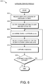
- Fig. 6 illustrates an exposure control process 600 performable by a camera system, such as the camera system 100a or 100b.
- a camera system such as the camera system 100a or 100b.
- the process 600 is described in the context of the camera system 100a but may instead be implemented by other systems described herein or other camera systems not shown.
- the process 600 provides one example approach by which the camera system 100a can control exposure using the optical element filter 102 while holding one or more other settings constant, substantially constant, or within a particular range of values.
- the controller 116 can receive a user input indicative of exposure settings for the camera system 100a.
- the user input for instance, can indicate one or more of a desired exposure level, size of the lens aperture, an adjustable shutter speed, adjustable sensitivity (e.g., ISO sensitivity value), a white balance setting, and depth of field.
- the controller 116 can receive the user input from a user interface (not shown) incorporated in the camera housing 104.
- the controller 116 can identify exposure settings for the camera system 100a to vary or keep constant based at least on the user input. For example, the controller 116 can determine to maintain a desired size of the lens aperture and shutter speed at a values or within ranges indicated by the user input, and the controller 116 can determine that the adjustable sensitivity, the white balance setting, and the depth of field may be varied.
- the controller 116 can determine a current exposure level for light entering the camera housing 104. For instance, the controller 116 can use an intensity of light detected by the image sensor 114 or another image sensor (e.g., a dedicated exposure level sensor) to determine the current exposure level.
- the controller 116 can use an intensity of light detected by the image sensor 114 or another image sensor (e.g., a dedicated exposure level sensor) to determine the current exposure level.
- the opacity of the optical filter 102 can at least be adjusted by the controller 116 to control the exposure level.
- the opacity of the optical filter 102 can be adjusted so as to bring the current exposure level closer to a desired exposure level indicated by the user input.
- the controller 116 can also adjust one or more of the exposure settings indicated to be variable based at least on the user input to control the exposure level.
- the controller 116 can maintain a level of the one or more exposure settings indicated to be kept constant based at least on the user input.
- the image sensor 114 can capture image data at the adjusted current exposure level.
- the controller 116 can determine whether to continue image data capture using the image sensor 114. If the controller 116 determines to continue image data capture, the process 600 moves to block 606, and the controller 116 can determine the current exposure level for light entering the camera housing 104. On the other hand, if the controller 116 determines not to continue image data capture, the process 600 ends.
- the image processor 119 process the image data generated by the image sensor 114 to account for certain optical effects caused by the optical filter 102. For instance, light passing through the optical filter 102 in some cases is color shifted.
- the optical filter 102 can include a liquid crystal panel that can pass more blue light than other colors of light as the opacity of the optical filter 102 increases. This effect may occur when the optical filter 102 is operating in the neutral density mode, for example, and relative amount of blue shift may generally increase with an increasing neutral density filtering stop value.
- the sensor can generate image data during capture that is biased towards blue such that blue values of the image data can be relatively higher than values for other colors of the image data.
- the white point of light passing through the optical filter 102 may shift, e.g., when the optical filter 102 is operating in a temporal filtering mode.
- the image processor 119 can modify the image data from the image sensor 114 in order to counteract or otherwise reduce the impact of such optical effects caused by the optical filter 102.
- the degree and type of modification can depend on a configuration (e.g., one or more settings) of the optical filter 102.
- the image processor 119 may reduce image data values for an appropriate color(s) (e.g., for blue image data) according to a pre-determined function.
- the function can be selected based on a selected neutral density stop value. For instance, since higher stop values can result in more color shift, a higher degree of reduction may be applied (e.g., to the blue color data) for increasing stop values in one implementations.
- the image processor 119 can adjust for a color shift or other effect resulting from use of the optical filter 102, such as a shift towards blue resulting from use of the optical filter 102 in a neutral density filtering mode, by applying an appropriate matrix operation to the image data from the image sensor 114.
- a colorimetry calibration involving application of a matrix may be applied to the image data.
- the colorimetry calibration can involve application of a white balance operation on the image data along with an RGB or other type of gain.
- the colorimetry calibration takes the image data from native values to XYZ, and can provide a calibration so that the white balance correlated color temperature in kelvin and tint (for colors above or below the Plankian locus) can be accurate.
- the colorimetry calibration can be different for different neutral density stop values, such as for each integer stop value.
- the calibration process can involve concatenating a matrix tailored to account for the effects of the optical filtering with the standard calibration of the camera system 100a, or can otherwise involve applying such a matrix together with the standard camera calibration.
- the colorimetry calibration that compensates for the optical filtering (e.g., neutral density filtering) and the standard camera color calibration can be applied together as a system. This is in contrast to applying a matrix to account for the neutral density or other optical filtering separately from the applying standard camera colorimetry calibration.
- a matrix tailored to account for the neutral density or other optical filtering is applied separately from the standard camera colorimetry calibration.
- the amount of data utilized to perform the colorimetry calibration can be advantageously reduced in certain implementations.
- in-between values can be interpolated.
- offsets into a neutral density table of calibrations can be used for the colorimetry calibration to account for the impact of individual shutter modes including temporal filtering and global shuttering modes.
- For the temporal filtering mode an offset increase of 0.67 stops relative to a neutral density associated with the temporal filtering mode can be used for the colorimetry calibration; while for the global shuttering mode, an offset increase of 0.00 stops relative to a neutral density associated with the global shuttering mode can be used for the colorimetry calibration.
- different offset increases can be used.
- a gain may be applied to the image data instead of or in addition to applying a matrix.
- an RGB gain or balance may be applied by the image processor 119 to the image data when the optical filter 102 is in use.
- the image processor 119 can vary the modification function applied to the image data depending on a shutter angle associated with the temporal filter function or a shutter angle (or effective shutter angle) associated with the image sensor 114.
- the modification function can generally act to return the image data for one or more of the colors (e.g., for red, green and blue image data) back to a desired white point.
- the image processor 119 can be configured to counteract multiple different types of optical effects caused by the optical filter 102.
- the optical filter 102 in some cases can cause both a color shift (e.g., a blue shift) and a white point shift, such as where the optical filter 102 provides both an effective neutral density function and a temporal filtering function.
- the image processor 119 can be configured in such cases to modify image data values to counteract both the color shift and the white point shift.
- the image processor 119 can beneficially apply a function for counteracting the white point shift before applying a function for counteracting the color shift.
- the image processor 119 can generally modify the image data values as part of the image processing pipeline, before the image data is written out to a file, e.g., before it is written out into a file on the memory 113 within the camera housing 104, or to some other storage device.
- the processing occurs additionally or alternatively in post-processing.
- the camera system 100a may incorporate image processing functionality such as compressed raw on-board image data handling disclosed in U.S. Patent No. 8,237,830, issued on August 7, 2012 , titled "VIDEO CAMERA,".
- Fig. 7 illustrates an image data modification process 700 performable by a camera system, such as the camera system 100a or 100b.
- a camera system such as the camera system 100a or 100b.
- the process 700 is described in the context of the camera system 100a but may instead be implemented by other systems described herein or other camera systems not shown.
- the process 700 provides one example approach by which the camera system 100a can counteract one or more different types of optical effects caused by the optical filter 102 on image data captured by the image sensor 114.
- the controller 116 can identify operation settings for the optical filter 102.
- the controller 116 can identify a neutral density setting (e.g., a neutral density stop value) or an operating mode (e.g., a temporal filtering or global shuttering modes) for the optical filter 102.
- the operation settings may have been set based at least on a user input received by the controller 116 from a user interface (not shown).
- the controller 116 can adjust the opacity of the optical filter 102 in accordance with the operation settings for the optical filter 102. For instance, if the operation settings indicate that the optical filter 102 should have a neutral density stop value of 2.5, the controller 116 can supply a signal to the optical filter 102 to cause the optical filter 102 to provide the neutral density stop value of 2.5. In another example, if the operation settings indicate that the optical filter 102 should operate in a temporal filtering mode, the controller 116 can supply a signal to the optical filter 102 that causes the optical filter 102 to generate an exposure window function to provide a temporal filtering functionality.
- the image sensor 114 can capture image data.
- the image processor 119 can modify values of the image data based at least on the operation settings for the optical filter 102. For example, the image processor 119 can modify the values based at least on the neutral density setting or operating mode for the optical filter 102. As a result, the image processor 119 can counteract one or more optical effects on the image data that are associated with the particular operation settings for the optical filter 102.
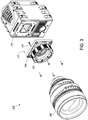
- Fig. 3 shows a camera system 300 that includes a lens mount 106 having an integrated optical filter 102, a lens 108, and a camera housing 104.
- the camera system 300 can be an example implementation of the camera system 100a of Fig. 1A .
- the camera housing 104 has a housing aperture.
- the optical filter 102 can include an electronically-controlled panel, such as a liquid crystal panel.
- Figs 4A-B respectively illustrate front and back perspective exploded views of the lens mount 106 of Fig. 3 .
- the lens mount 106 includes the optical filter 102, an electronics board 130, lens mounting components 132, an electrical connector 134, and camera mounting components 136.
- the lens mounting components 132 generally work together to provide a mechanism for fastening the lens 108 to the lens mount 106, while the camera mounting components 132 provide mechanism for mounting the lens mount 106 to the camera housing 104.
- the electronics board 130 includes electronics for controlling operation of the lens mount 106, the lens 108, and the optical filter 102.
- the electronics board 130 may include one or more application-specific integrated circuits (ASICs), field-programmable gate arrays (FPGAs), microprocessors, analog circuitry, and/or other custom circuitry, and the like.
- ASICs application-specific integrated circuits
- FPGAs field-programmable gate arrays
- microprocessors analog circuitry, and/or other custom circuitry, and the like.
- the electronics board 130 may comprise a printed circuit board, for example.
- the electrical connector 134 electronically couples the camera housing 104 to one or more of the lens mount 106 (e.g., to the electronics board 130 of the lens mount 106) and the lens 108 in certain embodiments.
- Fig. 3 shows the electrical connector 134 installed in an assembled lens mount 106.
- the optical filter 102 in the illustrated embodiment includes a rectangular, electronically-controllable, variable-opacity liquid crystal panel.
- a rectangular frame 142 holds the panel and defines a window (e.g., a hollow) for allowing the passage of light.
- a first set of contact strips 138 connect the optical filter 102 to the rear of one of the lens mounting components 132, while a second set of contact strips 140 connects the frame 140 to the electronics board 130.
- the first set of contact strips 138, the second set of contact strips 140, and the frame 142 are electrically conductive in one embodiment.
- drive signals from the electronics board 130 can be communicated to the liquid crystal panel via a signal path that is established from the electronics board 130 to the second set of contact strips 140, to the frame 142, to the first contact strips 138, and finally to electrodes on the periphery of the liquid crystal panel102.
- one or more of the components in the lens mount 106 generally can define an optical path through which light passes to an image sensor.
- each of the rear component of the lens mounting components 132, the optical filter 102, the frame 142, the electronics board 130, and the camera mount components 136 define substantially rectangular windows through which light can travel to the image sensor.
- the optical filter 102 can have a certain index of refraction, and insertion of the optical filter 102 can therefore change the overall focal length of a camera system. In particular, this can alter the optical distance from an image sensor plane to the back of the lens 108. In order to compensate for this effect, the overall length of the lens mount 106 can be increased as compared to a lens mount 106 not having the optical filter 102.
- the optical filter 102 includes a liquid crystal, and the length of the lens mount 106 can be greater by 0.898 millimeters as compared to a lens mount 106 not incorporating the optical filter 102 to compensate for the change in focal length due to the optical filter 102.
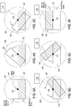
- Figs. 5A-F illustrates an embodiment of a mechanism for achieving this.
- the mechanism includes an optical filter 102, a substitute optical element 152, and a pivot point 154.
- Figs. 5A-F illustrate a front, simplified view, looking at the mechanism from in front of the camera, where an image sensor may lie behind the mechanism.
- the substitute optical element 154 can be made of a transmissive material (e.g., a glass panel) and can generally have the same shape and form factor as the optical filter 102.
- the optical filter 102 has a particular index of refraction, which affects the overall focal length of the camera system. Thus, removal of the optical filter 102 from the optical path will change the overall focal length of the camera system.
- the substitute optical element 154 can have the same or a substantially similar index of refraction as the optical filter 102. In this manner, the overall focal length of the camera system can remain constant or substantially constant, regardless of whether the optical filter 102 is in the optical path. In some other embodiments, a substitute optical element 154 is not used.
- the mechanism can be included in a lens mount, for example, and the dashed lines 150 can represent the perimeter of the lens mount.
- the mechanism could be included in a lens mount, such as the lens mounts 106 of Figs. 1A , 3 , and 4A-B .
- the mechanism may be provided in another location, such as within a camera housing.
- Figs. 5A-F sequentially illustrate movement of the substitute optical element 152 into the optical path, and the optical filter 102 out of the optical path.
- Figs. 5A-C show rotation of the substitute optical element 152 about the pivot point 154 and into the optical path
- Figs. 5D-F show rotation of the optical filter 102 out of the optical path.
- the substitute optical element 152 and the optical filter 102 can generally swap positions in the illustrated embodiment, which can minimize the real estate and foot print required to house the mechanism.
- the movement of the substitute optical element 152 and the optical filter 102 is shown as two separate steps for the purposes of illustration, the movement of the substitute optical element 152 and optical filter 102 may occur simultaneously, or may at least partially overlap in time.
- a similar process may be used to move the substitute optical element 152 back out of the optical path and to move the optical filter 102 back into the optical path.
- the process shown in Figs. 5A-F may be reversed to achieve this result, for example.
- Actuation of the mechanism is achieved via a mechanical control in certain embodiments.
- a lever or knob mechanically coupled to the mechanism can be provided on the outside of the lens mount, camera body, or other component housing the mechanism. Actuation of the lever or knob results in movement of the optical filter 102 into and out of the optical path, as desired.
- actuation of the mechanism is at least partially electronically or magnetically controlled, and can be initiated via user interaction with a GUI, button, or other camera control.
- the optical filter 102 can be connected to a controller, which may be the lens mount controller 118 described above with respect to Fig. 1A , for example, and may include drive electronics for driving the optical filter 102.
- An electronic connector connects the lens mount controller 118 to the optical filter 102.
- the electronic connector can have at least one flexible portion.
- the electronic connector in some embodiments includes at least two electrical conductors, both of which are connected to both the lens mount controller 118 at one end and to the variable opacity optical filter 102 at the other end.
- the connector can be flexible, it can bend or otherwise accommodate movement of the optical filter 102 into and out of the optical path. In some cases, it can be undesirable for components to move within the optical path of the system, e.g., to avoid contaminating the image sensor or to minimize disruption in image capture.
- the connector can be arranged such that no portion of connector passes through the optical path as the variable opacity optical filter 102 moves into and out of the optical path. This is shown in Fig. 5C-F .
- the mechanism can move the optical filter 102 out of the optical path by substantially reversing the movement shown in Figs. 5C-F .
- the optical filter 102 may move out of electrical and/or physical contact with control electronics when moved out of the optical path.
- the optical filter 102 can include a liquid crystal panel and be in communication with the electronics board 130 via the signal path established by the contacts 140, 138 and conducting frame 142.
- the liquid crystal panel 102 may be substantially irremovably coupled to one or more of the first set of contacts 138, the conducting frame 142, and the second set of contacts 140.
- any components that are irremovably coupled to the optical filter 102 move along with the optical filter 102, out of the optical path.
- the optical filter 102 and irremovably coupled components are temporarily electrically and physically decoupled from the electronics board 130 when it is out of the optical path.
- connectivity is re-established, e.g., via a friction fit.
- two, three, four or more optical filters 102 can be used.
- at least one of the optical filters 102 can operate in a temporal mode simultaneously with at least another optical filter 102 operating in a neutral density mode or global shuttering mode, etc.
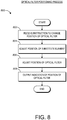
- Fig. 8 illustrates an optical filter positioning process 800 performable by a camera system, such as the camera system 100a or 100b.
- a camera system such as the camera system 100a or 100b.
- the process 800 is described in the context of the camera system 100a and the mechanism of Figs. 5A-F but may instead be implemented by other systems described herein or other camera systems not shown.
- the process 800 provides one example approach by which the camera system 100a can move the optical filter 102 into and out of the optical path of the image sensor 114, in conjunction with moving a substitute optical element into and out of the optical path.
- the controller 116 can receive an instruction to change the position of the optical filter 102.
- the instruction may be received by the controller 116 from a user interface (not shown), and the instruction can signify to move the optical filter 102 into the optical path of light entering the image sensor or to remove the optical filter 102 from the optical path.
- the controller 116 can adjust the position of the substitute element.
- the controller 116 can provide a signal to the lens mount controller 118 to cause the substitute element to be moved or removed from the optical path in accordance with the instruction.
- the substitute element and optical filter 102 may be positioned opposite from one another as illustrated in Figs. 5A and 5F . However, after the operation at block 804, the substitute element and optical filter 102 can be temporarily aligned with one another in or out of the optical path.
- the controller 116 can adjust the position of the optical filter 102.
- the controller 116 can, for instance, provide a signal to the lens mount controller 118 to cause the optical filter 102 to be moved or removed from the optical path in accordance with the instruction.
- the substitute element and optical filter 102 may again be not aligned with one another in or out of the optical path.
- the controller 116 can output an indication of the position of the optical filter 102 for display to a user of the camera system 100a. For example, since the movement or position of the optical filter 102 and substitute element may not be readily visible to the user, the controller 116 can output an indication of the position of the optical filter 102 for display on the user interface used to receive the instruction.
- acts, events, or functions of any of the methods described herein can be performed in a different sequence, can be added, merged, or left out altogether (e.g., not all described acts or events are necessary for the practice of the method). Moreover, in certain embodiments, acts or events can be performed concurrently, e.g., through multi-threaded processing, interrupt processing, or multiple processors or processor cores, rather than sequentially.
- the algorithms disclosed herein can be implemented as routines stored in a memory device. Additionally, a processor can be configured to execute the routines. In some embodiments, custom circuitry may be used.
- DSP digital signal processor
- ASIC application specific integrated circuit
- FPGA field programmable gate array
- a general purpose processor can be a microprocessor, but in the alternative, the processor can be any conventional processor, controller, microcontroller, or state machine.
- a processor can also be implemented as a combination of computing devices, e.g., a combination of a DSP and a microprocessor, a plurality of microprocessors, one or more microprocessors in conjunction with a DSP core, or any other such configuration.
- a software module can reside in RAM memory, flash memory, ROM memory, EPROM memory, EEPROM memory, registers, a hard disk, a removable disk, a CD-ROM, or any other form of computer-readable storage medium known in the art.
- An exemplary storage medium is coupled to a processor such that the processor can read information from, and write information to, the storage medium.
- the storage medium can be integral to the processor.
- the processor and the storage medium can reside in an ASIC.
- the ASIC can reside in a user terminal.
- the processor and the storage medium can reside as discrete components in a user terminal.
Landscapes
- Engineering & Computer Science (AREA)
- Multimedia (AREA)
- Signal Processing (AREA)
- Physics & Mathematics (AREA)
- General Physics & Mathematics (AREA)
- Blocking Light For Cameras (AREA)
- Studio Devices (AREA)
- Exposure Control For Cameras (AREA)
- Structure And Mechanism Of Cameras (AREA)
Description
- Motion picture film cameras expose film by allowing light to pass through a lens opening and then through a shutter aperture. In traditional motion picture cameras, a shutter rotates at a speed synchronous with that of passing film frames. Digital motion picture cameras, on the other hand, expose an image sensor by electronically controlling an exposure time for each frame to achieve a similar effect.
-
US 2012/062845 provides a system for and method of frequency prefiltering comprising a camera shutter capable of continuously variable illumination during a single exposure of the sensor, as well as a postfilter comprising a digital finite impulse response convolutional filter. - In an embodiment, a camera can include a camera housing, an image sensor within the camera housing, and a processor in communication with the image sensor. The image sensor can convert light entering the camera housing into digital image data. The light can pass through a variable opacity optical filter situated in the optical path prior to arriving at the image sensor. The processor can set operation settings for the optical filter at least in part according to a user input, generate control information that causes an opacity level of the optical filter to be controlled over an exposure period of each of a plurality of video image frames in accordance with the operation settings for the optical filter. When the operation settings for the optical filter indicate a temporal filtering mode, the processor is configured to generate the control information so that over the exposure period the optical filter gradually increases its transmissivity to a first level and subsequently gradually decreases the transmissivity from the first level before the end of the exposure period. When the operation settings for the optical filter indicate a global shutter mode, the processor is configured to generate the control information so that over the exposure period the optical filter maintains a second level of transmissivity, abruptly increases transmissivity from the second level to a third level, maintains the third level of transmissivity, and abruptly decreases transmissivity from the third level. The processor can modify values of the digital image data based at least on the operation settings for the optical filter to address color shifting in the digital image data introduced by the optical filter. The processor is configured to modify the values of the digital image data by reducing the values of the digital image data a greater amount when the operation settings for the optical filter indicate the temporal filtering mode than when the operation settings for the optical filter indicate the global shuttering mode.
- The operation settings for the optical filter can include a neutral density setting, and the processor can maintain the opacity level of the optical filter over the exposure period at an opacity level corresponding to the neutral density setting. The processor can modify the values of the digital image data by applying a matrix to the digital image data to at least counteract an effect of the optical filter on the digital image data. The processor can modify the values of the digital image data by applying the matrix to the digital image data to at least perform colorimetry calibration associated with one or more components other than the optical filter. The digital image data can include first, second, and third colors, and the processor can modify values for the first color based at least on the operation settings for the optical filter. The first color can include blue image data. The processor can modify the values of the first color by reducing the values for the first color a greater amount when an opacity level of the optical filter is at a first level than when the opacity level of the optical filter is at a second level different from the first level. The processor can modify the values of the digital image data so as to counteract a color shift caused by the optical filter. The processor can modify the values of the digital image data so as to counteract a white point shift in the digital image data caused by the optical filter. The processor can modify the values of the digital image data so as to counteract a white point shift in the digital image data caused by the optical filter. The processor can modify the values of the digital image data in accordance with a first function to counteract a white point shift in the digital image data caused by the optical filter and in accordance with a second function to counteract a color shift caused by the optical filter, and the processor can modify the values of the digital image data in accordance with the first function before modifying the values of the digital image data in accordance with the second function. The optical filter can be a part of a lens mount releasably connected to the camera housing. When the operation settings for the optical filter indicate a temporal filtering mode, the processor can modify the values of the digital image data based at least on a shutter angle associated with the optical filter. The processor can set the operation settings for the optical filter at least in part according to a user input. The optical filter can be included in a lens mount removably attached to the camera housing. The camera can further include the optical filter, which can be contained within the camera housing. The optical filter can include a liquid crystal panel. The processor can generate the control information so as to operate the optical filter in at least three different modes corresponding to: (i) the temporal filtering mode in which the optical filter gradually increases its transmissivity to a first level, and subsequently gradually decreases the transmissivity from the first level before the end of the exposure period; (ii) the global shutter mode wherein the optical filter (a) maintains a first level of transmissivity, (b) abruptly increases transmissivity from the first level to a second level, (c) maintains the second level of transmissivity, and (d) abruptly decreases transmissivity from the second level; and (iii) a neutral density mode wherein the opacity is maintained at a constant value over the exposure period.
- In an embodiment, a method of operating a camera includes: setting operation settings for a variable opacity optical filter (102) at least in part according to a user input; controlling, with a processor, an opacity level of the optical filter over an exposure period of each of a plurality of video image frames in accordance with the operation settings for the optical filter; converting, with an image sensor within a camera housing, light entering the camera housing into digital image data, the light passing through the optical filter prior to arriving at the image sensor; and wherein when the operation settings for the optical filter indicate a temporal filtering mode, the processor generating the control information so that over the exposure period the optical filter gradually increases its transmissivity to a first level and subsequently gradually decreases the transmissivity from the first level before the end of the exposure period, wherein when the operation settings for the optical filter indicates a global shutter mode, the processor generating the control information so that over the exposure period the optical filter maintains a second level of transmissivity, abruptly increases transmissivity from the second level to a third level, maintains the third level of transmissivity, and abruptly decreases transmissivity from the third level; modifying values of the digital image data based at least on the operation settings for the optical filter to address color shifting in the digital image data introduced by the optical filter; wherein said modifying comprises reducing the values of the digital image data a greater amount when the operation settings for the optical filter indicate the temporal filtering mode than when the operation settings for the optical filter indicate the global shuttering mode.
- The method of the preceding paragraph can include one or more of the following features: The operation settings for the optical filter can include a neutral density setting, and the method can further include maintaining an opacity level of the optical filter over the exposure period at a level that corresponds to the neutral density setting. The modifying can include applying a matrix to the digital image data to at least counteract an effect of the optical filter on the digital image data. The modifying can include modifying the digital image data in accordance with a first function to counteract a white point shift in the digital image data caused by the optical filter before modifying the digital image data in accordance with a second function to counteract a color shift caused by the optical filter.
- The drawings are provided to illustrate example embodiments described herein and are not intended to limit the scope of the disclosure. Throughout the drawings, reference numbers may be re-used to indicate general correspondence between referenced elements.
-
Fig. 1A illustrates a camera system including a lens mount having an optical filter. -
Fig. 1B illustrates a camera system having an optical filter within the camera housing. -
Fig. 2 is a plot of exposure window functions over a single frame. -
Fig. 3 shows a camera system including an embodiment of a lens mount having an integrated optical filter. -
Figs. 4A and4B respectively illustrate front and back perspective exploded views of the lens mount ofFigure 3 . -
Figs. 5A-F illustrate operation of an optical filter configured to move in and out of an optical path of a camera. -
Fig. 6 illustrates an exposure control process performable by a camera system. -
Fig. 7 illustrates an image data modification process performable by a camera system. -
Fig. 8 illustrates an optical filter positioning process performable by a camera system. -
Fig. 9 illustrates an embodiment of a camera system having a plurality of imagers and corresponding optical filters. - Various aspects of the disclosure will now be described with regard to certain examples and embodiments, which are intended to illustrate but not to limit the disclosure. Nothing in this disclosure is intended to imply that any particular feature or characteristic of the disclosed embodiments is essential. The scope of protection is defined by the claims that follow this description and not by any particular embodiment described herein.
- Systems, apparatus and methods are described herein for optical filtering, e.g., using one or more variable-opacity optical filters. The optical filters can be integrated with an existing camera component, such as a lens mount or camera body. The filters can operate in one or more of multiple modes, including modes for neutral density filtering, temporal filtering, or global shuttering.
-
Figs. 1A-C illustrate various configurations ofcamera systems optical filters 102. Thecamera systems camera system 100a ofFig. 1A includes acamera housing 104, alens mount 106, and alens 108. Thecamera housing 104 is provided with alens mount interface 110 for releasable attachment with acorresponding interface 112 of thelens mount 106. Thelens mount 106 further includes alens interface 114 configured to accept and support thelens 108. Thecamera system 100a may generally incorporate components or functionality of, or be otherwise similar to or the same as any of the cameras described inU.S. Patent No. 8,237,830, issued on August 7, 2012 , titled "VIDEO CAMERA" orU.S. Patent No. 8,525,925, issued on September 3, 2013 , titled "MODULAR DIGITAL CAMERA,". - The
camera system 100a includes at least oneimage sensor 114, at least onememory 113, at least onecontroller 116, at least oneimage processor 119 within thecamera housing 104. Thecontroller 116 generally manages operation of theimage sensor 114, and can be in communication with alens mount controller 118 of thelens mount 106 so as to synchronize operation of theoptical filter 102 andimage sensor 114. Thelens mount controller 118, in certain embodiments, communicates and controls operation of thelens 108, e.g., at the direction of thecontroller 116. Theimage processor 119 generally processes the image data output from theimage sensor 114. Before or after theimage processor 119 processes the image data, the image data can be stored to thememory 113. Theimage processor 119 can format the data stream from theimage sensor 114 in any known manner and can separate green, red, and blue image data into separate data compilations. For example, theimage processor 119 can separate the red data into one data element, the blue data into one blue data element, and the green data into one green data element. Although thecontroller 116 andimage processor 119 are shown as a separate processor and controller in the illustrated embodiment ofFig. 1 , thecontroller 116 andimage processor 119 can be implemented using the same processor or controller in other embodiments. - In some embodiments, the
camera system 100a also includes one or more of a compression module (not shown) for compressing image data, display (not shown) for displaying images to a user of thecamera system 100a, and display controller (not shown) for controlling the images shown by the display. The one or more of the compression module, display, and display controller can be in communication with theimage sensor 114, thememory 113, thecontroller 116, and theimage processor 119. The compression module can be incorporated within theimage processor 119, for example. - The
image sensor 114 can be any type of image sensing device, including, for example, but without limitation, CCD, CMOS, vertically-stacked CMOS devices such as the Foveon® sensor, or a multi-sensor array using a prism to divide light between the sensors. Theimage sensor 114 can provide variable resolution by selectively outputting a predetermined portion of theimage sensor 114, and theimage sensor 114 andimage processor 119 can allow a user to identify the resolution of the image data output. In addition, thesensor 114 can include a Bayer pattern filter. As such, thesensor 114, by way of its chipset (not shown) may output data representing magnitudes of red, green, or blue light detected by individual photocells of theimage sensor 114. The chipset of theimage sensor 114 can be used to read the charge on each element of the image sensor and thus output a stream of values in, for instance, RGB format output. In some configurations, thecamera 100a can be configured to record and/or output video (e.g., compressed raw video) at "2k" (e.g., 2048 x 1152 pixels), "4k" (e.g., 4,096 x 2,540 pixels), "4.5k" horizontal resolution, "5k" horizontal resolution (e.g., 5120 x 2700 pixels), "6k" horizontal resolution (e.g., 6144 x 3160), or greater resolutions. In some embodiments, the camera can be configured to record compressed raw image data having a horizontal resolution of between at least any of the above-recited resolutions. In further embodiments, the resolution is between at least one of the aforementioned values (or some value between the aforementioned values) and about 6.5k, 7k, 8k, 9k, or 10k, or some value therebetween). As used herein, in the terms expressed in the format of xk (such as 2k and 4k noted above), the "x" quantity refers to the approximate horizontal resolution. As such, "4k" resolution corresponds to about 4000 or more horizontal pixels and "2k" corresponds to about 2000 or more pixels. Using currently commercially available hardware, the sensor can be as small as about 0.5 inches (8 mm), but it can be about 1.0 inches, or larger. Additionally, theimage sensor 114 can be configured to provide variable resolution by selectively outputting only a predetermined portion of thesensor 114. For example, thesensor 114 and/or the image processing module can be configured to allow a user to identify the resolution of the image data output. Moreover, thecamera 100a can be configured to capture and/or record image data (e.g., compressed raw image data) at any of the above resolution levels at frame rates of These processes can also be applied to the processing of continuous video, e.g., at frame rates of greater than 23 frames per second, as well as frame rates of 20, 23.98, 24, 25, 29.97, 30, 47.96, 48, 50, 59.94, 60, 120, and 250 frames per second, or other frame rates between any of these frame rates or greater. - The
lens 108 can be supported by thelens mount 106 andcamera housing 104 in a manner that leaves thelens 108 exposed at the outer surface of thecamera housing 104. Thelens 108 can include one or more optics and focus incoming light onto a light-sensitive surface of theimage sensor 114. Thelens 108 can provide variable zoom, aperture, and focus functionality. Thelens 108 can include aniris diaphragm 107 in the optical path between a point in front of thelens 108 and theimage sensor 114. Theiris diaphragm 107 can include a diaphragm mechanism configured to define an adjustable-size aperture stop or hole in the optical path. Thelens 108 can include a focusingmechanism 109 disposed in the optical path and including at least one lens assembly configured to adjust a focus of light passing through the focusingmechanism 109 to theimage sensor 114. In addition, thelens 108 can include alens controller 111 that controls operations of theiris diaphragm 107 and focusingmechanism 109. Thelens controller 111 can control theiris diaphragm 107 and focusingmechanism 109, in some cases, at the direction of thecontroller 116. - The
lens mount controller 118 can also control operation of theoptical filter 102, e.g., at the direction of thecontroller 116. Theoptical filter 102 can be an electronically-controllable optical element. An opacity of theoptical filter 102 can be controlled according to a desired function to provide, for example, temporal filtering (e.g., to reduce temporal aliasing as described inU.S. Patent Application Publication No. 2012/0062845, published on March 15, 2012 , titled "APPARATUS AND METHOD FOR IMPROVED MOTION PICTURE CAMERAS", global shuttering, or neutral density filtering. For instance, theoptical filter 102 can include a liquid crystal element that can be controlled according to a drive voltage to vary the instantaneous illumination on theimage sensor 114 over the course of one or more exposures. In one implementation, the liquid crystal element may be opaque when supplied with a voltage (e.g., a sinusoidal AC voltage signal) and transparent when not supplied with a voltage, and the root mean square (RMS) of the supplied voltage can be increased to increase the opacity of the liquid crystal element and decreased to decrease the opacity of the liquid crystal element. The liquid crystal element can be overdriven (e.g., driven at an AC voltage that may not be maintained in steady-state operation), in some cases, to increase the speed of transition from transparent to opaque. In another implementation, a polarizer can be included in theoptical filter 102 in the optical path before or after the liquid crystal element, and by varying the supply of power to the liquid crystal element, the polarity of the liquid crystal element can be varied so as to control the illumination from opaque to transparent. In other instances, theoptical filter 102 can additionally or alternatively include one or more rotatable polarizers, an exposure control wafer including perforations, or one or more other optical filters usable to vary the instantaneous illumination on theimage sensor 114 over the course of one or more exposures. Thelens mount controller 118 and/or theoptical filter 102 can include drive electronics for changing the opacity of or otherwise driving theoptical filter 102. As a result, thelens mount 106 can at least in part take over shuttering duties for thecamera system 100a. For instance, thelens mount 106 can be considered to take over shuttering duties for thecamera system 100a when thecamera system 100a may be operating in the temporal filtering or global shuttering modes. - To provide temporal filtering, the
optical filter 102 can generally be controlled to provide prefiltering functionality. For example, theoptical filter 102 can provide intensity or illumination filtering over time to generate an exposure window function that exhibits some transitional values other than 0 (fully opaque) and 1 (fully transparent), in certain modes of operation. In one example, theoptical filter 102 functions as a prefilter to reduce temporal aliasing to provide an illumination that continuously varies and exhibits transitional values other than 0 (fully opaque) and 1 (fully transparent) during a single exposure. - The
plot 200 ofFig. 2 illustrates multiple example exposure window functions 1-6 producible by theoptical filter 102 for achieving temporal filtering, e.g., to reduce temporal aliasing and other types of motion artifacts. The exposure window functions 1-6 show an exposure (e.g., opacity or transmissivity) of theoptical filter 102 over time, where 1 may correspond to fully opaque and 0 may correspond to fully transparent. Compatible temporal filtering functions may, for example, gradually transition during a frame period from a "closed" state (e.g., at a fully opaque state or otherwise at a lowest level of transmissivity for the exposure period), to an "open" state (e.g., at a fully transparent or otherwise at a highest level of transmissivity for the exposure period), and then back to the closed state. The exposure window functions 1-4 illustrate example generally Gaussian-shaped exposure window functions for achieving temporal filtering, while the exposure window functions 5 and 6 respectively illustrate global shuttering and neutral density exposure window functions. Although the exposure window functions 1-6 are shown for a shutter speed or frame rate of 24 frames per second (fps), other shutter speeds or frame rates can be used in other cases, and exposure window functions having other shapes can be used in other cases. Moreover, in some modes of operation, a camera system like thecamera system 100a can enable different shutter angles to be selected and implemented. In such cases, the exposure window functions 1-6 can be applied to expose an image sensor to light for a duration corresponding to the shutter angle for the camera system. - As can be seen from the exposure window function 1 of
plot 200, for instance, the exposure of theoptical filter 102 can vary over time and, in some cases, over a single frame. The exposure of the exposure window function 1 can begin atpoint 7 with an exposure level of about 0.08 at time 0.000 seconds, steadily increase topoint 8 with an exposure level of about 0.52 at time 0.010 seconds, peak atpoint 9 with an exposure level of about 1.00 at time about 0.022 seconds, steadily decrease to point 10 with an exposure level of about 0.64 at time 0.030 seconds, and end atpoint 11 with the exposure level of about 0.08 at time about 0.043 seconds. Thus, the exposure window function 1 can be characterized over the course of a single frame by one or more of: (i) the initial exposure level, (ii) the rate of exposure level increase from the initial exposure level to the peak exposure level, (iii) the peak exposure level, (iv) the rate of exposure level decrease from the peak exposure level to the end exposure level, and (v) the end exposure level. In one example implementation, such as illustrated by the exposure window function 1, the opacity of theoptical filter 102 can vary gradually from an original opacity level to another opacity level and back to the original opacity level during a single frame, and the opacity level can transition through multiple intermediate opacity levels when adjusting between the original opacity level and the another opacity level. - As can be seen from the
exposure window function 5 ofplot 200, as another example, the exposure of theoptical filter 102 can vary over time and, in some cases, over a single frame in a way that may be relatively abrupt and less gradual than the transitions of the exposure window function 1. In particular, exposure of theexposure window function 5 can begin at an exposure level of about 0.00 at time 0.000 seconds, remain at the exposure level of about 0.00 until an initial time of about 0.018 seconds, abruptly increase to an exposure level of about 1.00 after the initial time of about 0.018 seconds, remain at the exposure level of about 1.00 until a subsequent time of about 0.023 seconds, abruptly decrease to the exposure level of about 0.00 after the subsequent time of about 0.023 seconds, and remain at the exposure level of about 0.00 until time 0.043. Theexposure window function 5, accordingly, can be characterized over the course of a single frame by one or more of: (i) the initial time when exposure level abruptly changes, (ii) the subsequent time when the exposure level again abruptly changes, (iii) a width period w between the initial time and subsequent time, and (iv) the exposure levels before and after the transitions. The illustrated waveform corresponding toexposure window function 5 corresponds to a global shutter mode having an associated shutter angle of about 42 degrees [(0.005s/0.043s) * 360 degrees)]. In one example implementation, such as illustrated by theexposure window function 5, the opacity of theoptical filter 102 can vary abruptly from an original opacity level to another opacity level and back to the original opacity level once during a single frame. - The
optical filter 102 can be controlled to provide a global shuttering function. For instance, the opacity of theoptical filter 102 can be controlled so that all of the image sensing elements of theimage sensor 114 can be exposed to light at the same time or substantially the same time, for example, such as by generating theexposure window function 5 ofplot 200. As shown, theoptical filter 102 can be controlled to generate a relatively sharp transition from a "closed" state, where thefilter 102 is at a maximum opacity level (or is at some other baseline level of opacity), to an "open" state, where thefilter 102 is at its maximum level of transmissivity (or is at some other top-end level of opacity). Thefilter 102 is held at the open state for a pre-defined duration before sharply transitioning back to the closed state. In this manner, the image sensing elements of theimage sensor 114 may be exposed to light for a relatively limited duration. The global shuttering function can eliminate, for instance, rolling shutter artifacts like partial illumination caused by strobe lights. In some cases, this type of global shuttering function is referred to as implementing a "hard" global shutter, or a "square shutter" because of the sharp transition from closed to open and open to closed. Conversely, the temporal filtering function described above can be referred to as a "soft" global shutter" or a "soft shutter", because there is a similar transition from closed to open, and back to closed, but it is a gradual transition. - The
optical filter 102 can also be controlled to provide a neutral density filtering function. For instance, where theoptical filter 102 is a liquid crystal, thelens mount controller 118 can provide a substantially constant amplitude signal to the liquid crystal so that the liquid crystal provides a desired constant opacity level throughout the entirety or the substantial entirety of the frame period. The amplitude of the signal can be controlled (e.g., based on a user-selected stop value) to achieve a desired opacity level and corresponding neutral density filtering effect. This is in contrast to the temporal filtering mode and the global shuttering modes, where the opacity level of theoptical filter 102 changes during one or more frame periods according to a filtering function. - In certain embodiments, the
optical filter 102 can be operated in at least three modes, e.g., the temporal filtering mode, the global shuttering mode, or the neutral density filtering mode. In some embodiments,optical filter 102 can be operated in at least one or two of the three modes. A user interface (not shown) can be provided to allow a user to configure operation and modes of theoptical filter 102. For instance, a graphical user interface provided on the display (not shown) of thecamera system 100a. Alternatively, one or more knobs, buttons or other controls may be provided. Having multiple modes of operation can be particularly useful in adapting to various shooting conditions and in providing users with creative flexibility. For many scenes, a typical rolling shutter can provide a "film-like" look to the recorded video, and may be appropriate in many situations. In such cases, the user can inactivate the optical filter 102 (or operate in neutral density mode) to capture data using the native rolling shutter of theimage sensor 114. - The square shutter, global shuttering mode (abrupt closed/open/closed) can be used where rolling shutter-induced motion artifacts are of particular concern, in order to provide a relatively accurate representation of motion. For instance, the global shutter mode can reduce striping or tearing artifacts from uncontrolled strobes or flashes, reduce the so called "jello" effect, so that fast-moving subjects are not angled or sheared, and can reduce blurring or wobbling due to rapid camera movements.
- On the other hand, where there is a desire to reduce temporal aliasing or other motion artifacts, while preserving a film-like look, the user can elect to put the
filter 102 in the soft-shutter, temporal filtering mode. The temporal filtering mode can generally provide the following benefits, among others: - Allow for proper capture of the direction of rotation of cyclical motion, such as a rotation propeller.
- Soften blur while preserving clarity.
- Reduce judder while panning.
- Render human movement relatively accurately and naturally.
- Reduce flickering without requiring continuous or synchronized lighting.
- Reduce striping or tearing artifacts from uncontrolled strobes and flashes.
- Reduce the "jello" effect.
- Reduce blurring and wobbling due to camera movement.
- The user interface may provide a variety of different programming options for the
optical filter 102. For example, a mode selection option may be provided to select between a neutral density filtering mode, a temporal filtering mode, and a global shuttering mode. In some embodiments, a combined temporal filtering and neutral density mode and a combined global shuttering and neutral density mode are also provided. Each mode may have corresponding user selectable options. For example, the optical filter can change the effective sensitivity to light ("effective ISO") of the camera, such as in the neutral density filtering mode where the effective ISO is reduced because theoptical filter 102 reduces light transmission to theimage sensor 114. To provide the user with a gauge as to the degree of this effect, the user interface can optionally display an effective ISO for image data so as to enable a user to better understand the impact of the opacity of theoptical filter 102 on the image data in view of one or more other camera settings. This user interface can provide both the effective ISO and the native ISO of theimage sensor 114. Moreover, the user interface can also allow the user to select a particular desired effective ISO, using a graphical slider or other type of control. In some embodiments, adjusting the effective ISO actually adjusts the cameras native ISO, not the opacity of theoptical filter 102, which may instead be controlled by adjusting the neutral density stop value, for example. The user interface can additionally allow the user to select a value for the native ISO directly, in addition to the indirect adjustment achieved via selection of the desired effective ISO. - For the neutral density filtering mode, a user may be able to select an effective stop value. In one embodiment, the user can interact with the user interface to program the
optical filter 102 to behave as a neutral density filter, and can select a stop value from 1.5 to 9.0 in 1/10 stop increments. In some embodiments, the neutral density filter has stop values from 0.01 to 9.0 in 1/100, 1/10, or 1 stop increments (e.g., 0.01, 1.0, 1.43, 2.0, 3.0, 4.0, 5.0, 6.0, 7.0, 8.0, 9.0). In particular embodiments, neutral density filtering can be always active when thelens mount 106 is connected to thecamera housing 104 such thecamera system 100a can operate in one of three select modes: (1) the neutral density filtering mode, (2) the combined temporal filtering and neutral density mode, and (3) the combined global shuttering and neutral density mode. - In some embodiments, the range of stop values for the
camera system 100a can depend on the mode of operation. For example, when operating in the neutral density mode and not the temporal filtering or global shuttering modes, the allowable range of stop values for theoptical filter 102 can be from 1.6 to 8.0 stops. On the other hand, when operating in the temporal filtering or global shuttering modes, the allowable range of stop values for theoptical filter 102 can be from 1.6 to 4.0 stops. - For the temporal filtering and global shuttering modes, the interface may allow the user to select a shutter angle for the
optical filter 102. When operating in the temporal filtering mode, theoptical filter 102 may also behave as a neutral density filter. In some embodiments, the user can select one of a group of temporal filtering functions, each of which provide a different result (e.g., a different amount or quality of aliasing reduction). - As discussed, a combined temporal filtering and neutral density mode and a combined global shuttering and neutral density mode may also be provided. In such cases, a user may also be able to select a stop value for the neutral density function, similar to the stand-alone neutral density mode. In the combined temporal filtering and neutral density mode, in one example, the general shape of the function applied to the
optical filter 102 may be similar to the exposure window function 1 shown in theplot 200 ofFig. 2 . For instance, the shape of the exposure window function may be Gaussian or otherwise substantially symmetric about a peak that is reached substantially mid-way through the frame period (or mid-way through a portion of the frame period corresponding to a selected shutter angle for the temporal filtering function). However, depending on the stop value, the average transparency (or opacity) of theoptical filter 102 over the duration of the frame may change. For instance, referring to theplot 200 ofFig. 2 , the exposure window function 1 or a portion thereof may be generally squashed or shifted down with increasing stop values, or be otherwise adjusted to further reduce the amount of light passing through the optical filter during the frame period. For example, the exposure window function 1 can be generally reduced to become theexposure window function 2 of theplot 200. Conversely, for instance, theexposure window function 2 or a portion thereof may generally shift upwards with decreasing stop values, or be otherwise adjusted to increase the average amount of light passing through the optical filter during the frame period. For example, theexposure window function 2 can be generally increased to become the exposure window function 1 of theplot 200. - In some cases, the
optical filter 102 can pass light through theoptical filter 102 in a manner that results in an increase in the amount of infrared or other contamination incident on theimage sensor 114. Such cases can include when operating theoptical filter 102 in a neutral density filtering mode, when not operating theoptical filter 102 in the neutral density filtering mode but with a high neutral density, or when operating theoptical filter 102 in a temporal filtering mode or global shuttering mode. As an example, theoptical filter 102 may act in operation as an infrared pass filter that allows a significant increase in the amount of infrared light to reach theimage sensor 114. To counteract such effects, thecamera system 100a may include one or more filters (not shown) placed in the optical path. The one or more filters can be an optical low pass filter (OLPF), anti-aliasing filter, IR cut-off filter, or heat-absorbing filter, for example, and can be considered one or more additional filters because thecamera housing 104 may also additionally include a different OLPF, and the additional filter is used to block additional infrared or other contamination resulting from the use of theoptical filter 102. In one embodiment, the additional filter can include an optical coating or film adhered to or otherwise deposited on one or more surfaces of theoptical filter 102. For instance, where theoptical filter 102 is a liquid crystal display panel, an optical coating or film configured to pass visible light but block infrared light may be applied to a glass cover or other surface of the liquid crystal display panel (or be otherwise to appropriately applied to the liquid crystal display panel). In other cases, an antireflection or other type of coating can be applied instead of or in addition to the additional filter. In yet other cases, the additional filter may comprise a physically separate panel or other optical component, not adhered to or otherwise forming a part of theoptical filter 102. In such cases, the additional filter may be positioned at any appropriate point in the optical path. - Where filtering is not desired, the
optical filter 102 can also be selectively deactivated. For instance, where a liquid crystal is used, the liquid crystal can be controlled to exhibit a maximum level of transparency. However, in some cases, the liquid crystal oroptical filter 102 has some minimal level of opacity or other optical effect that may be undesirable where filtering is not wanted. To address this, theoptical filter 102 can be removed from the optical path in some cases. One such case is discussed further with respect toFigs. 5A-F . - As shown in
Fig. 1A , theoptical filter 102 can be incorporated into thelens mount 106. Thus, users can enjoy the benefits of theoptical filter 102 via standard installation of thelens mount 106, and without having to attach a separate, dedicated filtering component. Moreover, signals for controlling theoptical filter 102 can be routed along acommunication pathway 117 directly from thecamera housing 104 via theinterface 112, e.g., without the use of an external cabling or external camera ports. This configuration provides seamless integration of theoptical filter 102 into the system. In addition, decoupling theoptical filter 102 functionality from thecamera housing 104 provides system modularity. For instance, existing customers can benefit from the use of theoptical filter 102 by purchasing a relativelyinexpensive lens mount 106 having theoptical filter 102, without having to purchase a significantly moreexpensive camera housing 104 that includes theoptical filter 102. Similarly, as upgrades to theoptical filter 102 become available, users can benefit from the upgrades by purchasing anew lens mount 106 instead of anew camera housing 104. Other customers can opt to purchase a lower cost system by purchasing a standard lens mount that does not include theoptical filter 102. Thelens mount 106 incorporating theoptical filter 102 and/or other implementations ofoptical filters 102 described herein can be incorporated into modular cameras such as the ones described inU.S. Patent No. 8,525,924, issued on September 3, 2013 , and titled "MODULAR MOTION CAMERA". - In other cases, the
optical filter 102 is incorporated into thecamera housing 104. For instance,Fig. 1B illustrates acamera system 100b similar to thecamera system 100a ofFig. 1A where theoptical filter 102 is provided within or is otherwise supported by thecamera housing 104. As a result, thelens mount 106 may also not include thelens mount controller 118. This implementation can provide certain benefits. For example, becauseoptical filter 102 may be more tightly coupled to thecontroller 116 and other electronics within thecamera housing 104, communication with theoptical filter 102 for synchronization and other control purposes may be more reliable, and design complexity may be reduced. - In some embodiments, multiple
optical filters 102 can be employed. For instance, in one embodiment, at least a secondoptical filter 102 is positioned after the firstoptical filter 102 in the optical path. Each of the multipleoptical filters 102 may of the same type (e.g., liquid crystal panels), or different types can be used. Moreover, the multipleoptical filters 102 can provide different functions. For instance, in one embodiment, one of the multipleoptical filters 102 can be used to provide neutral density filtering, and the another of the multipleoptical filters 102 is used to provide temporal filtering. -
Fig. 9 illustrates acamera system 900 similar to thecamera system 100a ofFig. 1 that incorporates multipleoptical filters 102. Thecamera system 900 includesmultiple image sensors 114 andcorresponding lenses 108. One or more of the multipleoptical filters 102 can be included in the optical path between acorresponding lens 108 andimage sensor 114. In some cases, one or more of theoptical filters 102 may instead be positioned before thecorresponding lens 108 in the optical path. The combination of theimage sensor 114 and acorresponding lens 108 may be referred to as an imager. - For conventional cameras, scene lighting changes are sometimes accounted for by manual or automatic adjustment of aperture, shutter speed, or both to maintain desired exposure. Such changes however, can alter the quality or character of a shot in an undesirable manner, by altering depth of field, desired motion effect, or the like. It can therefore be desirable to maintain constant or substantially constant certain camera settings, such as aperture, shutter speed, depth of field, sensitivity (ISO), color temperature, and the like, while maintaining an exposure at a desired level or within a desired range. This can be particularly true in shooting environments where lighting conditions often change dramatically, such as for outdoor exposures where clouds may move over the sun.
- In some embodiments, the
optical filter 102 can be controlled so as to control exposure, such as an exposure level associated with digital image data captured by an image sensor114. For example, the opacity of theoptical filter 102 can be controlled so as to adjust the amount of light incident on theimage sensor 114, thereby maintaining a constant or substantially constant exposure level (or maintaining an exposure level within a desired range). As shown, theoptical filter 102 or other optical element can be positioned along an optical path between a point outside of the camera body and theimage sensor 114. - A user can, according to some aspects, select an exposure value (or exposure range), and the
controller 116 can control theoptical filter 102 to maintain or substantially maintain the selected exposure value (or range). For instance, in some cases, the opacity of theoptical filter 102 is adjusted to control the amount of light incident on theimage sensor 114 instead of adjusting one or more of an aperture of thelens 108, a shutter speed (e.g., a digital shutter speed of theimage sensor 114 and/or a mechanical shutter speed of the lens 108), and a light sensitivity of the image sensor 114 (e.g., ISO sensitivity). Thus, using theoptical filter 102 to maintain exposure can provide the benefit of achieving desired exposure under changing lighting conditions, while also maintaining certain camera settings at desired levels (e.g., a desired aperture, shutter speed, light sensitivity, or color temperature). - In some cases, the
image sensor 114 implements an electronic shutter, e.g., via controlled sensor pixel activation and de-activation. Moreover, thecamera system camera system image sensor 114 in the optical path. - The
camera system optical filter 102. For instance, referring toFig. 1A , the exposure controller can be implemented by one or more of thecontroller 116 within thecamera housing 104 and thelens mount controller 118 within thelens mount 106. - The exposure controller can be configured to adjust the at least one optical characteristic in response to changes in lighting conditions external to the
camera system camera system image sensor 114, for example. In such cases, scene lighting changes can be determined based an analysis of the image data, and the exposure controller adjusts the optical characteristic accordingly. - In some cases, the exposure controller controls the
optical filter 102 based on an amount of light detected by theimage sensor 114, e.g., based on an average light value or some other appropriate algorithm. A variety of different exposure metering techniques can be employed, including center-weighted average metering, spot metering (e.g., where exposure control is based on an analysis of image data corresponding to an area of between about 1%-5% or about 1%-10% of the image), partial area metering, (e.g., where exposure control is based on an analysis of image data corresponding to a partial image area of between about 10-15% of the image), multi-zone metering, and matrix metering, to name a few. - In one implementation, the exposure controller controls the
optical filter 102 based on an analysis of a pixel brightness histogram or exposure histogram. As an example, the exposure controller may track the location(s) of one or more peaks in the histogram (exposure values for which there are relatively high numbers of image sensor pixels having those exposure values). In one embodiment, if the peak(s) move toward an end of the histogram corresponding to darker exposure values, this is an indication that objects in the image scene are becoming under exposed, and the exposure controller adjusts the optical filter 102 (e.g., decreases opacity) to increase exposure. If, on the other hand, the peak(s) move toward an end of the histogram corresponding to brighter exposure values, this can be an indication that objects in the image scene are becoming over exposed, and the exposure controller adjusts the optical element (e.g., increases opacity) to decrease exposure. - In some implementations, the exposure controller is configured adjust the at least one optical characteristic in response to changes in lighting conditions detected by a second sensor that is separate than the
image sensor 114. For instance, a second image sensor or other type of sensor may be used, which in some cases can be dedicated for use in detecting lighting conditions. - As indicated, it can be useful to control exposure using the
optical filter 102 while holding one or more settings constant, substantially constant, or within a particular range of values while adjusting the exposure. For example, the exposure controller may modulate theoptical filter 102 to control exposure while thecamera system - Moreover, while maintaining one or more of the above settings at a desired level in this manner, the exposure controller can additionally adjust the at least one optical characteristic (e.g., opacity of the optical filter 102) in order to maintain an overall exposure level at a constant level, a substantially constant level, or within a particular range. For instance, the exposure controller can adjust the at least one optical characteristic in order to maintain an exposure level within a range of plus or minus no more than about 0.5%, 1%, 2%, 3%, 4%, 5%, 10%, 20%, 30%, 40%, 50%, or more of an initial or baseline (e.g., user selected) exposure level, for example. In some cases, the exposure controller maintains the exposure level within plus or minus a particular (e.g., user selected) number of stops (e.g., 1, 2, 3, 4, or more stops) of an initial or baseline (e.g., user selected) stop value.
-
Fig. 6 illustrates anexposure control process 600 performable by a camera system, such as thecamera system process 600 is described in the context of thecamera system 100a but may instead be implemented by other systems described herein or other camera systems not shown. Theprocess 600 provides one example approach by which thecamera system 100a can control exposure using theoptical element filter 102 while holding one or more other settings constant, substantially constant, or within a particular range of values. - At
block 602, thecontroller 116 can receive a user input indicative of exposure settings for thecamera system 100a. The user input, for instance, can indicate one or more of a desired exposure level, size of the lens aperture, an adjustable shutter speed, adjustable sensitivity (e.g., ISO sensitivity value), a white balance setting, and depth of field. Thecontroller 116 can receive the user input from a user interface (not shown) incorporated in thecamera housing 104. - At
block 604, thecontroller 116 can identify exposure settings for thecamera system 100a to vary or keep constant based at least on the user input. For example, thecontroller 116 can determine to maintain a desired size of the lens aperture and shutter speed at a values or within ranges indicated by the user input, and thecontroller 116 can determine that the adjustable sensitivity, the white balance setting, and the depth of field may be varied. - At
block 606, thecontroller 116 can determine a current exposure level for light entering thecamera housing 104. For instance, thecontroller 116 can use an intensity of light detected by theimage sensor 114 or another image sensor (e.g., a dedicated exposure level sensor) to determine the current exposure level. - At
block 608, the opacity of theoptical filter 102 can at least be adjusted by thecontroller 116 to control the exposure level. For example, the opacity of theoptical filter 102 can be adjusted so as to bring the current exposure level closer to a desired exposure level indicated by the user input. Thecontroller 116 can also adjust one or more of the exposure settings indicated to be variable based at least on the user input to control the exposure level. Moreover, at the same time, thecontroller 116 can maintain a level of the one or more exposure settings indicated to be kept constant based at least on the user input. - At
block 610, theimage sensor 114 can capture image data at the adjusted current exposure level. Atblock 612, thecontroller 116 can determine whether to continue image data capture using theimage sensor 114. If thecontroller 116 determines to continue image data capture, theprocess 600 moves to block 606, and thecontroller 116 can determine the current exposure level for light entering thecamera housing 104. On the other hand, if thecontroller 116 determines not to continue image data capture, theprocess 600 ends. - When using the
optical filter 102, theimage processor 119 process the image data generated by theimage sensor 114 to account for certain optical effects caused by theoptical filter 102. For instance, light passing through theoptical filter 102 in some cases is color shifted. Theoptical filter 102 can include a liquid crystal panel that can pass more blue light than other colors of light as the opacity of theoptical filter 102 increases. This effect may occur when theoptical filter 102 is operating in the neutral density mode, for example, and relative amount of blue shift may generally increase with an increasing neutral density filtering stop value. Thus, the sensor can generate image data during capture that is biased towards blue such that blue values of the image data can be relatively higher than values for other colors of the image data. Depending on the type of theoptical filter 102 used, other types of color shifting may occur (e.g., a shift in red, green, a shift in two colors, etc.). As another example, the white point of light passing through theoptical filter 102 may shift, e.g., when theoptical filter 102 is operating in a temporal filtering mode. - The
image processor 119 can modify the image data from theimage sensor 114 in order to counteract or otherwise reduce the impact of such optical effects caused by theoptical filter 102. The degree and type of modification can depend on a configuration (e.g., one or more settings) of theoptical filter 102. For instance, in order to address the color shifting effect, theimage processor 119 may reduce image data values for an appropriate color(s) (e.g., for blue image data) according to a pre-determined function. The function can be selected based on a selected neutral density stop value. For instance, since higher stop values can result in more color shift, a higher degree of reduction may be applied (e.g., to the blue color data) for increasing stop values in one implementations. - In some cases, the
image processor 119 can adjust for a color shift or other effect resulting from use of theoptical filter 102, such as a shift towards blue resulting from use of theoptical filter 102 in a neutral density filtering mode, by applying an appropriate matrix operation to the image data from theimage sensor 114. For instance, a colorimetry calibration involving application of a matrix may be applied to the image data. The colorimetry calibration can involve application of a white balance operation on the image data along with an RGB or other type of gain. The colorimetry calibration, according to certain aspects, takes the image data from native values to XYZ, and can provide a calibration so that the white balance correlated color temperature in kelvin and tint (for colors above or below the Plankian locus) can be accurate. Moreover, the colorimetry calibration can be different for different neutral density stop values, such as for each integer stop value. The calibration process can involve concatenating a matrix tailored to account for the effects of the optical filtering with the standard calibration of thecamera system 100a, or can otherwise involve applying such a matrix together with the standard camera calibration. In this manner, the colorimetry calibration that compensates for the optical filtering (e.g., neutral density filtering) and the standard camera color calibration can be applied together as a system. This is in contrast to applying a matrix to account for the neutral density or other optical filtering separately from the applying standard camera colorimetry calibration. In some other cases, a matrix tailored to account for the neutral density or other optical filtering is applied separately from the standard camera colorimetry calibration. - The amount of data utilized to perform the colorimetry calibration can be advantageously reduced in certain implementations. In one example, in-between values can be interpolated. Alternatively or additionally, in another example, offsets into a neutral density table of calibrations can be used for the colorimetry calibration to account for the impact of individual shutter modes including temporal filtering and global shuttering modes. For the temporal filtering mode, an offset increase of 0.67 stops relative to a neutral density associated with the temporal filtering mode can be used for the colorimetry calibration; while for the global shuttering mode, an offset increase of 0.00 stops relative to a neutral density associated with the global shuttering mode can be used for the colorimetry calibration. In other examples, different offset increases can be used.
- The above-described approaches involving application of the matrix, e.g., to account for color shifting or other effects due to neutral density filtering can provide beneficial results. For example, such a technique can result in images having more accurate color over a range of neutral density stop values. In alternative embodiments, a gain may be applied to the image data instead of or in addition to applying a matrix. For instance, an RGB gain or balance may be applied by the
image processor 119 to the image data when theoptical filter 102 is in use. - To address the white point shift described above, the
image processor 119 can vary the modification function applied to the image data depending on a shutter angle associated with the temporal filter function or a shutter angle (or effective shutter angle) associated with theimage sensor 114. The modification function can generally act to return the image data for one or more of the colors (e.g., for red, green and blue image data) back to a desired white point. - In some cases, the
image processor 119 can be configured to counteract multiple different types of optical effects caused by theoptical filter 102. For instance, theoptical filter 102 in some cases can cause both a color shift (e.g., a blue shift) and a white point shift, such as where theoptical filter 102 provides both an effective neutral density function and a temporal filtering function. Theimage processor 119 can be configured in such cases to modify image data values to counteract both the color shift and the white point shift. In some embodiments, theimage processor 119 can beneficially apply a function for counteracting the white point shift before applying a function for counteracting the color shift. - The
image processor 119 can generally modify the image data values as part of the image processing pipeline, before the image data is written out to a file, e.g., before it is written out into a file on thememory 113 within thecamera housing 104, or to some other storage device. In some alternative embodiments, the processing occurs additionally or alternatively in post-processing. In certain embodiments, thecamera system 100a may incorporate image processing functionality such as compressed raw on-board image data handling disclosed inU.S. Patent No. 8,237,830, issued on August 7, 2012 , titled "VIDEO CAMERA,". -
Fig. 7 illustrates an imagedata modification process 700 performable by a camera system, such as thecamera system process 700 is described in the context of thecamera system 100a but may instead be implemented by other systems described herein or other camera systems not shown. Theprocess 700 provides one example approach by which thecamera system 100a can counteract one or more different types of optical effects caused by theoptical filter 102 on image data captured by theimage sensor 114. - At
block 702, thecontroller 116 can identify operation settings for theoptical filter 102. For example, thecontroller 116 can identify a neutral density setting (e.g., a neutral density stop value) or an operating mode (e.g., a temporal filtering or global shuttering modes) for theoptical filter 102. The operation settings may have been set based at least on a user input received by thecontroller 116 from a user interface (not shown). - At
block 704, thecontroller 116 can adjust the opacity of theoptical filter 102 in accordance with the operation settings for theoptical filter 102. For instance, if the operation settings indicate that theoptical filter 102 should have a neutral density stop value of 2.5, thecontroller 116 can supply a signal to theoptical filter 102 to cause theoptical filter 102 to provide the neutral density stop value of 2.5. In another example, if the operation settings indicate that theoptical filter 102 should operate in a temporal filtering mode, thecontroller 116 can supply a signal to theoptical filter 102 that causes theoptical filter 102 to generate an exposure window function to provide a temporal filtering functionality. - At
block 706, theimage sensor 114 can capture image data. Atblock 708, theimage processor 119 can modify values of the image data based at least on the operation settings for theoptical filter 102. For example, theimage processor 119 can modify the values based at least on the neutral density setting or operating mode for theoptical filter 102. As a result, theimage processor 119 can counteract one or more optical effects on the image data that are associated with the particular operation settings for theoptical filter 102. -
Fig. 3 shows acamera system 300 that includes alens mount 106 having an integratedoptical filter 102, alens 108, and acamera housing 104. Thecamera system 300 can be an example implementation of thecamera system 100a ofFig. 1A . Thecamera housing 104 has a housing aperture. Theoptical filter 102 can include an electronically-controlled panel, such as a liquid crystal panel.Figs 4A-B respectively illustrate front and back perspective exploded views of thelens mount 106 ofFig. 3 . Referring toFig. 4A , thelens mount 106 includes theoptical filter 102, anelectronics board 130,lens mounting components 132, anelectrical connector 134, andcamera mounting components 136. - The
lens mounting components 132 generally work together to provide a mechanism for fastening thelens 108 to thelens mount 106, while thecamera mounting components 132 provide mechanism for mounting thelens mount 106 to thecamera housing 104. - The
electronics board 130 includes electronics for controlling operation of thelens mount 106, thelens 108, and theoptical filter 102. For instance, theelectronics board 130 may include one or more application-specific integrated circuits (ASICs), field-programmable gate arrays (FPGAs), microprocessors, analog circuitry, and/or other custom circuitry, and the like. Theelectronics board 130 may comprise a printed circuit board, for example. - The
electrical connector 134 electronically couples thecamera housing 104 to one or more of the lens mount 106 (e.g., to theelectronics board 130 of the lens mount 106) and thelens 108 in certain embodiments.Fig. 3 shows theelectrical connector 134 installed in an assembledlens mount 106. - The
optical filter 102 in the illustrated embodiment includes a rectangular, electronically-controllable, variable-opacity liquid crystal panel. Arectangular frame 142 holds the panel and defines a window (e.g., a hollow) for allowing the passage of light. A first set of contact strips 138 connect theoptical filter 102 to the rear of one of thelens mounting components 132, while a second set of contact strips 140 connects theframe 140 to theelectronics board 130. The first set of contact strips 138, the second set of contact strips 140, and theframe 142 are electrically conductive in one embodiment. Thus, drive signals from theelectronics board 130 can be communicated to the liquid crystal panel via a signal path that is established from theelectronics board 130 to the second set of contact strips 140, to theframe 142, to the first contact strips 138, and finally to electrodes on the periphery of the liquid crystal panel102. - Referring again to
Fig. 4A , one or more of the components in thelens mount 106 generally can define an optical path through which light passes to an image sensor. For instance, in the illustrated embodiment, each of the rear component of thelens mounting components 132, theoptical filter 102, theframe 142, theelectronics board 130, and thecamera mount components 136 define substantially rectangular windows through which light can travel to the image sensor. - The
optical filter 102 can have a certain index of refraction, and insertion of theoptical filter 102 can therefore change the overall focal length of a camera system. In particular, this can alter the optical distance from an image sensor plane to the back of thelens 108. In order to compensate for this effect, the overall length of thelens mount 106 can be increased as compared to alens mount 106 not having theoptical filter 102. For instance, in one embodiment, theoptical filter 102 includes a liquid crystal, and the length of thelens mount 106 can be greater by 0.898 millimeters as compared to alens mount 106 not incorporating theoptical filter 102 to compensate for the change in focal length due to theoptical filter 102. - As discussed, it can be advantageous to move the
optical filter 102 out of the optical path when not in use.Figs. 5A-F illustrates an embodiment of a mechanism for achieving this. The mechanism includes anoptical filter 102, a substituteoptical element 152, and apivot point 154.Figs. 5A-F illustrate a front, simplified view, looking at the mechanism from in front of the camera, where an image sensor may lie behind the mechanism. - The substitute
optical element 154 can be made of a transmissive material (e.g., a glass panel) and can generally have the same shape and form factor as theoptical filter 102. As discussed above, theoptical filter 102 has a particular index of refraction, which affects the overall focal length of the camera system. Thus, removal of theoptical filter 102 from the optical path will change the overall focal length of the camera system. In order to address this, the substituteoptical element 154 can have the same or a substantially similar index of refraction as theoptical filter 102. In this manner, the overall focal length of the camera system can remain constant or substantially constant, regardless of whether theoptical filter 102 is in the optical path. In some other embodiments, a substituteoptical element 154 is not used. - The mechanism can be included in a lens mount, for example, and the dashed
lines 150 can represent the perimeter of the lens mount. For instance, the mechanism could be included in a lens mount, such as the lens mounts 106 ofFigs. 1A ,3 , and4A-B . In other embodiments, the mechanism may be provided in another location, such as within a camera housing. -
Figs. 5A-F sequentially illustrate movement of the substituteoptical element 152 into the optical path, and theoptical filter 102 out of the optical path. For instance,Figs. 5A-C show rotation of the substituteoptical element 152 about thepivot point 154 and into the optical path, andFigs. 5D-F show rotation of theoptical filter 102 out of the optical path. As shown, the substituteoptical element 152 and theoptical filter 102 can generally swap positions in the illustrated embodiment, which can minimize the real estate and foot print required to house the mechanism. - While the movement of the substitute
optical element 152 and theoptical filter 102 is shown as two separate steps for the purposes of illustration, the movement of the substituteoptical element 152 andoptical filter 102 may occur simultaneously, or may at least partially overlap in time. Moreover, while not shown, when use of theoptical filter 102 is desired, a similar process may be used to move the substituteoptical element 152 back out of the optical path and to move theoptical filter 102 back into the optical path. Or, the process shown inFigs. 5A-F may be reversed to achieve this result, for example. - Actuation of the mechanism is achieved via a mechanical control in certain embodiments. For instance, a lever or knob mechanically coupled to the mechanism can be provided on the outside of the lens mount, camera body, or other component housing the mechanism. Actuation of the lever or knob results in movement of the
optical filter 102 into and out of the optical path, as desired. In other embodiments, actuation of the mechanism is at least partially electronically or magnetically controlled, and can be initiated via user interaction with a GUI, button, or other camera control. - As shown, the
optical filter 102 can be connected to a controller, which may be thelens mount controller 118 described above with respect toFig. 1A , for example, and may include drive electronics for driving theoptical filter 102. An electronic connector connects thelens mount controller 118 to theoptical filter 102. The electronic connector can have at least one flexible portion. The electronic connector in some embodiments includes at least two electrical conductors, both of which are connected to both thelens mount controller 118 at one end and to the variable opacityoptical filter 102 at the other end. - As shown in
Figs. 5C-F , because the connector can be flexible, it can bend or otherwise accommodate movement of theoptical filter 102 into and out of the optical path. In some cases, it can be undesirable for components to move within the optical path of the system, e.g., to avoid contaminating the image sensor or to minimize disruption in image capture. As such, the connector can be arranged such that no portion of connector passes through the optical path as the variable opacityoptical filter 102 moves into and out of the optical path. This is shown inFig. 5C-F . To keep the connector out of the optical path when returning theoptical filter 102 into the optical path, the mechanism can move theoptical filter 102 out of the optical path by substantially reversing the movement shown inFigs. 5C-F . - Other mechanisms are possible for managing electrical connectivity when the
optical filter 102 is moved in and out of the optical path. For instance, instead of using a flexible connector, theoptical filter 102 may move out of electrical and/or physical contact with control electronics when moved out of the optical path. As an example, referring toFigs. 4A-B , theoptical filter 102 can include a liquid crystal panel and be in communication with theelectronics board 130 via the signal path established by thecontacts frame 142. The liquid crystal panel 102may be substantially irremovably coupled to one or more of the first set ofcontacts 138, the conductingframe 142, and the second set ofcontacts 140. When theoptical filter 102 is moved out of the optical path, any components that are irremovably coupled to theoptical filter 102 move along with theoptical filter 102, out of the optical path. As such, theoptical filter 102 and irremovably coupled components are temporarily electrically and physically decoupled from theelectronics board 130 when it is out of the optical path. Conversely, when theoptical filter 102 and any irremovably coupled components move back into the optical path, connectivity is re-established, e.g., via a friction fit. - In some other embodiments, two, three, four or more optical filters 102 (e.g., two or more liquid crystal display panels) can be used. In some such cases, at least one of the
optical filters 102 can operate in a temporal mode simultaneously with at least anotheroptical filter 102 operating in a neutral density mode or global shuttering mode, etc. -
Fig. 8 illustrates an opticalfilter positioning process 800 performable by a camera system, such as thecamera system process 800 is described in the context of thecamera system 100a and the mechanism ofFigs. 5A-F but may instead be implemented by other systems described herein or other camera systems not shown. Theprocess 800 provides one example approach by which thecamera system 100a can move theoptical filter 102 into and out of the optical path of theimage sensor 114, in conjunction with moving a substitute optical element into and out of the optical path. - At
block 802, thecontroller 116 can receive an instruction to change the position of theoptical filter 102. The instruction may be received by thecontroller 116 from a user interface (not shown), and the instruction can signify to move theoptical filter 102 into the optical path of light entering the image sensor or to remove theoptical filter 102 from the optical path. - At
block 804, thecontroller 116 can adjust the position of the substitute element. For example, thecontroller 116 can provide a signal to thelens mount controller 118 to cause the substitute element to be moved or removed from the optical path in accordance with the instruction. In one implementation, during normal operation of thecamera system 100a, the substitute element andoptical filter 102 may be positioned opposite from one another as illustrated inFigs. 5A and 5F . However, after the operation atblock 804, the substitute element andoptical filter 102 can be temporarily aligned with one another in or out of the optical path. - At
block 806, thecontroller 116 can adjust the position of theoptical filter 102. Thecontroller 116 can, for instance, provide a signal to thelens mount controller 118 to cause theoptical filter 102 to be moved or removed from the optical path in accordance with the instruction. After the operation atblock 806, the substitute element andoptical filter 102 may again be not aligned with one another in or out of the optical path. - At
block 808, thecontroller 116 can output an indication of the position of theoptical filter 102 for display to a user of thecamera system 100a. For example, since the movement or position of theoptical filter 102 and substitute element may not be readily visible to the user, thecontroller 116 can output an indication of the position of theoptical filter 102 for display on the user interface used to receive the instruction. - The preceding examples can be repeated with similar success by substituting generically or specifically described operating conditions of this disclosure for those used in the preceding examples.
- Although the disclosure has been described in detail with particular reference to these preferred embodiments, other embodiments can achieve the same results. Variations and modifications of the present disclosure will be obvious to those skilled in the art and it is intended to cover all such modifications and equivalents.
- Embodiments have been described in connection with the accompanying drawings. However, it should be understood that the figures are not drawn to scale. Distances, angles, etc. are merely illustrative and do not necessarily bear an exact relationship to actual dimensions and layout of the devices illustrated. In addition, the foregoing embodiments have been described at a level of detail to allow one of ordinary skill in the art to make and use the devices, systems, etc. described herein. A wide variety of variation is possible. Components, elements, and/or steps can be altered, added, removed, or rearranged. While certain embodiments have been explicitly described, other embodiments will become apparent to those of ordinary skill in the art based on this disclosure.
- Conditional language used herein, such as, among others, "can," "could," "might," "may," "e.g.," and the like, unless specifically stated otherwise, or otherwise understood within the context as used, is generally intended to convey that certain embodiments include, while other embodiments do not include, certain features, elements and/or states. Thus, such conditional language is not generally intended to imply that features, elements and/or states are in any way required for one or more embodiments or that one or more embodiments necessarily include logic for deciding, with or without author input or prompting, whether these features, elements and/or states are included or are to be performed in any particular embodiment. The terms "comprising," "including," "having," and the like are synonymous and are used inclusively, in an open-ended fashion, and do not exclude additional elements, features, acts, operations, and so forth. Also, the term "or" is used in its inclusive sense (and not in its exclusive sense) so that when used, for example, to connect a list of elements, the term "or" means one, some, or all of the elements in the list. Conjunctive language such as the phrase "at least one of X, Y and Z," unless specifically stated otherwise, is otherwise understood with the context as used in general to convey that an item, term, etc. may be either X, Y or Z. Thus, such conjunctive language is not generally intended to imply that certain embodiments require at least one of X, at least one of Y and at least one of Z to each be present.
- Depending on the embodiment, certain acts, events, or functions of any of the methods described herein can be performed in a different sequence, can be added, merged, or left out altogether (e.g., not all described acts or events are necessary for the practice of the method). Moreover, in certain embodiments, acts or events can be performed concurrently, e.g., through multi-threaded processing, interrupt processing, or multiple processors or processor cores, rather than sequentially. In some embodiments, the algorithms disclosed herein can be implemented as routines stored in a memory device. Additionally, a processor can be configured to execute the routines. In some embodiments, custom circuitry may be used.
- The various illustrative logical blocks, modules, circuits, and algorithm steps described in connection with the embodiments disclosed herein can be implemented as electronic hardware, computer software, or combinations of both. To clearly illustrate this interchangeability of hardware and software, various illustrative components, blocks, modules, circuits, and steps have been described above generally in terms of their functionality. Whether such functionality is implemented as hardware or software depends upon the particular application and design constraints imposed on the overall system. The described functionality can be implemented in varying ways for each particular application, but such implementation decisions should not be interpreted as causing a departure from the scope of the disclosure.
- The various illustrative logical blocks, modules, and circuits described in connection with the embodiments disclosed herein can be implemented or performed with a general purpose processor, a digital signal processor (DSP), an application specific integrated circuit (ASIC), a field programmable gate array (FPGA) or other programmable logic device, discrete gate or transistor logic, discrete hardware components, or any combination thereof designed to perform the functions described herein. A general purpose processor can be a microprocessor, but in the alternative, the processor can be any conventional processor, controller, microcontroller, or state machine. A processor can also be implemented as a combination of computing devices, e.g., a combination of a DSP and a microprocessor, a plurality of microprocessors, one or more microprocessors in conjunction with a DSP core, or any other such configuration.
- The blocks of the methods and algorithms described in connection with the embodiments disclosed herein can be embodied directly in hardware, in a software module executed by a processor, or in a combination of the two. A software module can reside in RAM memory, flash memory, ROM memory, EPROM memory, EEPROM memory, registers, a hard disk, a removable disk, a CD-ROM, or any other form of computer-readable storage medium known in the art. An exemplary storage medium is coupled to a processor such that the processor can read information from, and write information to, the storage medium. In the alternative, the storage medium can be integral to the processor. The processor and the storage medium can reside in an ASIC. The ASIC can reside in a user terminal. In the alternative, the processor and the storage medium can reside as discrete components in a user terminal.
- While the above detailed description has shown, described, and pointed out novel features as applied to various embodiments, it will be understood that various omissions, substitutions, and changes in the form and details of the devices or algorithms illustrated can be made. As will be recognized, certain embodiments of the inventions described herein can be embodied within a form that does not provide all of the features and benefits set forth herein, as some features can be used or practiced separately from others. The scope of certain inventions disclosed herein is indicated by the appended claims rather than by the foregoing description.
Claims (15)
- A camera (100a), comprising:a camera housing (104);an image sensor (114) within the camera housing (104) and configured to convert light entering the camera housing (104) into digital image data, the light passing through a variable opacity optical filter (102) situated in the optical path prior to arriving at the image sensor (114); anda processor (116, 119) in communication with the image sensor (114) and configured to:set operation settings for the optical filter (102) at least in part according to a user input,generate control information that causes an opacity level of the optical filter (102) to be controlled over an exposure period of each of a plurality of video image frames in accordance with the operation settings for the optical filter (102), andwherein when the operation settings for the optical filter (102) indicate a temporal filtering mode, the processor (116/119) is configured to generate the control information so that over the exposure period the optical filter (102) gradually increases its transmissivity to a first level and subsequently gradually decreases the transmissivity from the first level before the end of the exposure period,wherein when the operation settings for the optical filter (102) indicate a global shutter mode, the processor (116/119) is configured to generate the control information so that over the exposure period the optical filter (102) maintains a second level of transmissivity, abruptly increases transmissivity from the second level to a third level, maintains the third level of transmissivity, and abruptly decreases transmissivity from the third level;modify values of the digital image data based at least on the operation settings for the optical filter (102) to address color shifting in the digital image data introduced by the optical filter (102);wherein the processor (116/119) is configured to modify the values of the digital image data by reducing the values of the digital image data a greater amount when the operation settings for the optical filter (102) indicate the temporal filtering mode than when the operation settings for the optical filter (102) indicate the global shuttering mode.
- The camera (100a) of claim 1, wherein the processor (116/119) is configured to modify the values of the digital image data by applying a matrix to the digital image data to at least counteract an effect of the optical filter on the digital image data.
- The camera (100a) of claim 2, wherein the processor (116/119) is configured to modify the values of the digital image data by applying the matrix to the digital image data to at least perform colorimetry calibration associated with one or more components other than the optical filter (102).
- The camera (100a) of claim 1, wherein the digital image data comprises first, second, and third colors, and the processor (116/119) is configured to modify values for the first color a greater amount than values of the second color based at least on the operation settings for the optical filter (102), preferably wherein the first color comprises blue image data.
- The camera (100a) of claim 4, wherein the processor (116/119) is configured to modify the values of the first color by reducing the values for the first color a greater amount when the opacity level of the optical filter is at a fourth level than when the opacity level of the optical filter is at a fifth level different from the fourth level.
- The camera (100a) of claim 1, wherein the optical filter (102) is a part of a lens mount (106) releasably connected to the camera housing (104).
- The camera (100a) of claim 1, wherein when the operation settings for the optical filter (102) indicate the temporal filtering mode, the processor (116/119) is configured to modify the values of the digital image data based at least on a shutter angle associated with the optical filter (102).
- The camera (100a) of claim 1, wherein the optical filter (102) is included in a lens mount (106) removably attached to the camera housing (104).
- The camera (100a) of claim 1, further comprising the optical filter (102), which is contained within the camera housing (104).
- The camera (100a) of claim 1, wherein the optical filter (102) comprises a liquid crystal panel.
- The camera (100a) of claim 1, wherein when the operation settings for the optical filter (102) indicate a neutral density mode, the processor (116/119) is configured to generate the control information so that the opacity level is maintained at a constant value over the exposure period.
- The camera (100a) of claim 1, wherein the processor (116/119) is configured to set the operation settings for the optical filter (102) to indicate the temporal filtering mode or the global shuttering mode according to the user input.
- A method of operating a camera (100a), comprising:setting operation settings for a variable opacity optical filter (102) at least in part according to a user input;controlling, with a processor (116/119), an opacity level of the optical filter (102) over an exposure period of each of a plurality of video image frames in accordance with the operation settings for the optical filter;converting, with an image sensor (114) within a camera housing (104), light entering the camera housing into digital image data, the light passing through the optical filter prior to arriving at the image sensor; andwherein when the operation settings for the optical filter (102) indicate a temporal filtering mode, the processor (116/119) generating the control information so that over the exposure period the optical filter (102) gradually increases its transmissivity to a first level and subsequently gradually decreases the transmissivity from the first level before the end of the exposure period,wherein when the operation settings for the optical filter (102) indicates a global shutter mode, the processor (116/119) generating the control information so that over the exposure period the optical filter (102) maintains a second level of transmissivity, abruptly increases transmissivity from the second level to a third level, maintains the third level of transmissivity, and abruptly decreases transmissivity from the third level;modifying values of the digital image data based at least on the operation settings for the optical filter (102) to address color shifting in the digital image data introduced by the optical filter (102);wherein said modifying comprises reducing the values of the digital image data a greater amount when the operation settings for the optical filter (102) indicate the temporal filtering mode than when the operation settings for the optical filter (102) indicate the global shuttering mode.
- The method of claim 13, wherein the digital image data comprises first, second, and third colors, and said modifying comprises modifying values for the first color a greater amount than values of the second color based at least on the operation settings for the optical filter (102), preferably wherein the first color comprises blue image data.
- The method of claim 13, wherein said setting comprises setting the operation settings for the optical filter (102) to indicate the temporal filtering mode or the global shuttering mode according to the user input.
Applications Claiming Priority (4)
| Application Number | Priority Date | Filing Date | Title |
|---|---|---|---|
| US201361809260P | 2013-04-05 | 2013-04-05 | |
| US201361877459P | 2013-09-13 | 2013-09-13 | |
| US201361882575P | 2013-09-25 | 2013-09-25 | |
| PCT/US2014/032871 WO2014165698A1 (en) | 2013-04-05 | 2014-04-03 | Optical filtering for cameras |
Publications (3)
| Publication Number | Publication Date |
|---|---|
| EP2984520A1 EP2984520A1 (en) | 2016-02-17 |
| EP2984520A4 EP2984520A4 (en) | 2016-12-21 |
| EP2984520B1 true EP2984520B1 (en) | 2018-11-28 |
Family
ID=51654187
Family Applications (1)
| Application Number | Title | Priority Date | Filing Date |
|---|---|---|---|
| EP14778580.2A Active EP2984520B1 (en) | 2013-04-05 | 2014-04-03 | Optical filtering for cameras |
Country Status (7)
| Country | Link |
|---|---|
| US (3) | US9380220B2 (en) |
| EP (1) | EP2984520B1 (en) |
| JP (1) | JP6422942B2 (en) |
| KR (1) | KR102010628B1 (en) |
| CN (1) | CN105264880B (en) |
| ES (1) | ES2700733T3 (en) |
| WO (1) | WO2014165698A1 (en) |
Families Citing this family (56)
| Publication number | Priority date | Publication date | Assignee | Title |
|---|---|---|---|---|
| US10944917B2 (en) * | 2013-09-16 | 2021-03-09 | Kyle L. Baltz | Camera and image processing method |
| EP3062509B1 (en) * | 2013-12-06 | 2020-06-03 | Huawei Device Co., Ltd. | Terminal and image processing method |
| US9491373B2 (en) * | 2013-12-10 | 2016-11-08 | Sody Co., Ltd. | Light control apparatus for an image sensing optical device |
| JP6558362B2 (en) * | 2014-03-31 | 2019-08-14 | ソニー株式会社 | Control apparatus, control method, and imaging apparatus |
| JP2015198292A (en) * | 2014-03-31 | 2015-11-09 | ソニー株式会社 | Imaging apparatus, flicker correction method and program |
| US9602804B2 (en) * | 2015-03-26 | 2017-03-21 | Intel Corporation | Methods of forming integrated package structures with low Z height 3D camera |
| JP6671872B2 (en) * | 2015-06-22 | 2020-03-25 | キヤノン株式会社 | Adapter device, imaging device, and imaging system |
| US10440288B2 (en) * | 2015-09-02 | 2019-10-08 | Microsoft Technology Licensing, Llc | Methods and apparatuses for capturing image frames with interlaced exposure |
| JP2017054030A (en) * | 2015-09-10 | 2017-03-16 | ソニー株式会社 | Imaging device and shading correction method |
| JP2017062466A (en) * | 2015-09-25 | 2017-03-30 | キヤノン株式会社 | Optical apparatus and camera system using the same |
| US10139654B2 (en) * | 2015-09-25 | 2018-11-27 | Canon Kabushiki Kaisha | Optical apparatus that reduces driving noised by adjusting light transmissivity and camera system |
| US10067069B2 (en) * | 2016-03-11 | 2018-09-04 | Smart Vision Lights | Machine vision systems incorporating polarized electromagnetic radiation emitters |
| JP6862222B2 (en) * | 2016-04-12 | 2021-04-21 | キヤノン株式会社 | Adapter and camera system |
| US10142558B2 (en) * | 2016-04-12 | 2018-11-27 | Canon Kabushiki Kaisha | Adaptor and camera system |
| CN105959583A (en) * | 2016-04-28 | 2016-09-21 | 努比亚技术有限公司 | Mobile terminal and exposure method thereof |
| CN105872401A (en) * | 2016-04-29 | 2016-08-17 | 努比亚技术有限公司 | Light reduction device for adjusting transmittance and terminal thereof and transmittance control method |
| US10775605B2 (en) | 2016-06-16 | 2020-09-15 | Intel Corporation | Combined biometrics capture system with ambient free IR |
| WO2018057492A1 (en) * | 2016-09-23 | 2018-03-29 | Apple Inc. | Camera shades |
| US10713520B2 (en) * | 2016-10-27 | 2020-07-14 | Engineering Innovation, Inc. | Method of taking a picture without glare |
| US10291861B2 (en) * | 2016-12-05 | 2019-05-14 | Hubbell Incorporated | Privacy device and method for use with network enabled cameras |
| CN106603772B (en) * | 2017-01-26 | 2019-12-27 | Oppo广东移动通信有限公司 | Electronic device and image acquisition method |
| KR102057065B1 (en) | 2017-02-23 | 2019-12-18 | 동우 화인켐 주식회사 | Optical stack structure integrated with polarizer and touch sensor and display device including the same |
| EP4227728A1 (en) * | 2017-03-08 | 2023-08-16 | Meta Platforms Technologies, LLC | Wide angle variable neutral density filter |
| US11049898B2 (en) | 2017-04-01 | 2021-06-29 | Ningbo Sunny Opotech Co., Ltd. | Systems and methods for manufacturing semiconductor modules |
| KR102334464B1 (en) * | 2017-04-12 | 2021-12-02 | 닝보 써니 오포테크 코., 엘티디. | Camera module, molded photosensitive assembly and manufacturing method thereof, and electronic device |
| US11294113B2 (en) | 2017-07-17 | 2022-04-05 | Gary Sharp Innovations, Llc | Wide-angle compensation of uniaxial retarder stacks |
| CN111095910B (en) * | 2017-09-14 | 2021-01-12 | 富士胶片株式会社 | Imaging control device, imaging device, imaging control method, and recording medium |
| EP3746822A4 (en) | 2018-01-29 | 2022-01-12 | Gary Sharp Innovations, LLC | HOLLOW THREE-WAY OPTICAL ELEMENTS |
| US11249355B2 (en) | 2018-01-29 | 2022-02-15 | Gary Sharp Innovations, Llc | Color switch for reduced color cross-talk |
| JP7284182B2 (en) | 2018-03-02 | 2023-05-30 | メタ プラットフォームズ テクノロジーズ, リミテッド ライアビリティ カンパニー | Retarder Stack Pairs for Conversion of Polarization Basis Vectors |
| US12316939B2 (en) * | 2018-04-13 | 2025-05-27 | Panavision International, L.P. | Camera lens system filter |
| US11184510B2 (en) * | 2018-04-13 | 2021-11-23 | Panavision International, L.P. | Electronic camera filter |
| CN108955881A (en) * | 2018-06-28 | 2018-12-07 | 佛山市方垣机仪设备有限公司 | A kind of novel spectrometer |
| JP7173768B2 (en) * | 2018-07-04 | 2022-11-16 | キヤノン株式会社 | Electronic viewfinder and imaging device |
| US11199735B2 (en) * | 2019-03-28 | 2021-12-14 | Lumcolor | Smart optical filter for pixel-selectively adjusting light intensity |
| US10924690B2 (en) * | 2019-04-17 | 2021-02-16 | Google Llc | Electronically controlling optical transmission of a lens of a camera in variable lighting |
| CN110032022B (en) * | 2019-04-22 | 2020-12-11 | 嘉兴方沐能源科技有限公司 | A self-adjusting filter monitor |
| JP7348756B2 (en) | 2019-06-21 | 2023-09-21 | キヤノン株式会社 | Imaging device, control method and program |
| CN111193880B (en) * | 2020-01-13 | 2022-05-24 | 刘元哲 | Image sensor, optical filter and image sensor brightness adjusting method |
| US11516378B2 (en) | 2020-04-27 | 2022-11-29 | Qualcomm Incorporated | Methods and apparatus employing a phase detection autofocus (PDAF) optical system |
| US12189158B2 (en) * | 2020-06-18 | 2025-01-07 | Samsung Electronics Co., Ltd. | Optical multi-pass imaging device based on polarization elements and optical image capturing system for electronic mobile devices |
| CN113820879A (en) * | 2020-12-02 | 2021-12-21 | 法国圣戈班玻璃公司 | Liquid crystal projection layer for glass, vehicle and method for manufacturing glass |
| CN113163128B (en) * | 2021-05-08 | 2023-09-12 | 维沃移动通信(杭州)有限公司 | Image exposure method and electronic device |
| CN113542596B (en) * | 2021-06-29 | 2022-08-19 | 中国科学院长春光学精密机械与物理研究所 | Imaging control method of CCD imager |
| GB2611285A (en) * | 2021-09-09 | 2023-04-05 | Aptiv Tech Ltd | Camera assembly |
| US12529887B1 (en) | 2021-10-11 | 2026-01-20 | Bae Systems Space & Mission Systems Inc. | Optomechanical relay system and method for rapid filter switching |
| TW202331392A (en) * | 2021-11-29 | 2023-08-01 | 美商派納維景國際股份有限公司 | Electronic camera filter |
| CN116266880A (en) * | 2021-12-16 | 2023-06-20 | 三赢科技(深圳)有限公司 | Camera component, manufacturing method thereof, and terminal device |
| JP2023100417A (en) * | 2022-01-06 | 2023-07-19 | パナソニックIpマネジメント株式会社 | Imaging device |
| US11818465B2 (en) * | 2022-01-10 | 2023-11-14 | Gopro, Inc. | Systems, apparatus, and methods for stabilization and blending of exposures |
| US12513395B2 (en) | 2022-01-10 | 2025-12-30 | Gopro, Inc. | Systems, apparatus, and methods for stabilization and blending of exposures |
| DE102022107815A1 (en) * | 2022-04-01 | 2023-10-05 | Arnold & Richter Cine Technik Gmbh & Co. Betriebs Kg | Method for capturing a sequence of images |
| CN115185152A (en) * | 2022-06-24 | 2022-10-14 | 长春理工大学 | A catadioptric panoramic vision detection device with an anti-exposure system and an anti-exposure method |
| US12620067B2 (en) | 2023-03-23 | 2026-05-05 | Gopro, Inc. | Motion blur for multilayer motion |
| USD1096890S1 (en) * | 2023-11-10 | 2025-10-07 | SAM-Dimension GmbH | Camera |
| US12568312B2 (en) * | 2024-08-15 | 2026-03-03 | Adeia Imaging Llc | Mitigating rolling shutter effect using an adjustable transparency layer |
Family Cites Families (124)
| Publication number | Priority date | Publication date | Assignee | Title |
|---|---|---|---|---|
| US1800057A (en) | 1928-12-26 | 1931-04-07 | Radio Inventions Inc | Television |
| US2052960A (en) | 1930-04-22 | 1936-09-01 | Berggren Per Johan | Shutter for motion picture cameras |
| US2062960A (en) | 1934-11-30 | 1936-12-01 | Robert E Barclay | Means for and method of initiating and controlling electroical discharge in a gaseous conduction path |
| US2351932A (en) | 1940-01-08 | 1944-06-20 | Hans C Deckel | Shutter |
| US2514302A (en) | 1946-03-02 | 1950-07-04 | Aiken Thomas Mcg | Rotary blade shutter with flash lamp synchronizing switch |
| US3270646A (en) | 1964-04-14 | 1966-09-06 | Trenel Finance Corp | Camera attachment and camera |
| US4812911A (en) * | 1986-01-28 | 1989-03-14 | Canon Kabushiki Kaisha | Adapter with built-in shutter |
| US4889424A (en) | 1987-12-18 | 1989-12-26 | Panavision, Inc. | Movie camera shutter |
| US5063450A (en) | 1990-11-28 | 1991-11-05 | Eastman Kodak Company | Method and apparatus for preventing aliasing in an electronic still camera |
| JPH0591388A (en) * | 1991-09-20 | 1993-04-09 | Canon Inc | Mount conversion adapter and camera system with same |
| US5691830A (en) | 1991-10-11 | 1997-11-25 | International Business Machines Corporation | Holographic optical system including waveplate and aliasing suppression filter |
| US5371655A (en) | 1992-05-22 | 1994-12-06 | Panavision International, L.P. | System for varying light intensity such as for use in motion picture photography |
| US5956044A (en) | 1993-05-07 | 1999-09-21 | Eastman Kodak Company | Imaging device to media compatibility and color appearance matching with flare, luminance, and white point comparison |
| JPH07212639A (en) | 1994-01-25 | 1995-08-11 | Sony Corp | Electronic shutter device for television and camera |
| US20010012067A1 (en) | 1996-04-12 | 2001-08-09 | Stuart M. Spitzer | High definition television progressive scan broadcast camera |
| US5850277A (en) | 1996-05-30 | 1998-12-15 | Panavision, Inc. | Movie camera having adjustable shutter |
| JPH1010405A (en) | 1996-06-19 | 1998-01-16 | Canon Inc | Lens device and imaging device |
| US6115556A (en) | 1997-04-10 | 2000-09-05 | Reddington; Terrence P. | Digital camera back accessory and methods of manufacture |
| US6040857A (en) | 1997-05-27 | 2000-03-21 | Eastman Kodak Company | Phase-noise type broad spectral bandwidth optical low-pass anti-aliasing filter |
| US6088058A (en) | 1997-05-29 | 2000-07-11 | Foveon, Inc. | Capacitive coupled bipolar active pixel imager having overflow protection and electronic shutter |
| US20040201707A1 (en) | 1998-03-12 | 2004-10-14 | Kazuhiro Noguchi | Variable magnification lens having image stabilizing function |
| JP3997602B2 (en) | 1998-05-13 | 2007-10-24 | ソニー株式会社 | Light control device |
| JP4273372B2 (en) * | 1998-07-31 | 2009-06-03 | ソニー株式会社 | Imaging device |
| JP2000227618A (en) * | 1999-02-04 | 2000-08-15 | Canon Inc | Optical system with light intensity adjustment device |
| US6864916B1 (en) * | 1999-06-04 | 2005-03-08 | The Trustees Of Columbia University In The City Of New York | Apparatus and method for high dynamic range imaging using spatially varying exposures |
| US6930723B1 (en) | 1999-07-13 | 2005-08-16 | Canon Kabushiki Kaisha | Quantity-of-light adjusting apparatus |
| DE60035075T2 (en) | 1999-11-12 | 2008-01-24 | Sony Corp. | A light modulation device, image pickup device and method of its exposure time control |
| US7420585B2 (en) | 1999-11-30 | 2008-09-02 | Eastman Kodak Company | Image capture and display device |
| JP2001186401A (en) | 1999-12-24 | 2001-07-06 | Minolta Co Ltd | Digital camera |
| US6330400B1 (en) | 2000-01-28 | 2001-12-11 | Concord Camera-Corp. | Compact through-the-lens digital camera |
| US7245325B2 (en) * | 2000-03-17 | 2007-07-17 | Fujifilm Corporation | Photographing device with light quantity adjustment |
| JP2002082358A (en) | 2000-09-06 | 2002-03-22 | Sony Corp | Light control device and imaging device |
| JP2002122843A (en) | 2000-10-12 | 2002-04-26 | Sony Corp | Light control device, driving method thereof, and imaging device |
| JP4534340B2 (en) * | 2000-10-31 | 2010-09-01 | ソニー株式会社 | Color reproduction correction device |
| US6876412B2 (en) | 2001-04-06 | 2005-04-05 | Sony Corporation | Guest-host liquid crystal element with removable polarizer |
| WO2002086607A1 (en) | 2001-04-20 | 2002-10-31 | Sony Corporation | Electric dimming device and its driving method |
| US20030052989A1 (en) * | 2001-07-18 | 2003-03-20 | Bean Heather Noel | Non-polarizing shutter/CCD module |
| US7106377B2 (en) * | 2001-07-25 | 2006-09-12 | Hewlett-Packard Development Company, L.P. | Image capturing device capable of single pixel exposure duration control |
| US20030020958A1 (en) * | 2001-07-30 | 2003-01-30 | Bean Heather Noel | Non-polarizing shutter/CCD module |
| JP4439767B2 (en) * | 2001-08-09 | 2010-03-24 | キヤノン株式会社 | Imaging apparatus, white balance adjustment method, and operation processing program thereof |
| JP3918500B2 (en) * | 2001-10-24 | 2007-05-23 | ソニー株式会社 | Imaging device |
| JP3873739B2 (en) | 2001-12-18 | 2007-01-24 | ソニー株式会社 | A liquid crystal light amount adjusting device, a liquid crystal light amount adjusting device driving method, and a camera using the liquid crystal light amount adjusting device. |
| JP4028358B2 (en) | 2002-02-05 | 2007-12-26 | 株式会社リコー | Imaging apparatus, display control method, program, and recording medium |
| JP3577718B2 (en) | 2002-05-10 | 2004-10-13 | ソニー株式会社 | Light control device and imaging device |
| US20050046703A1 (en) | 2002-06-21 | 2005-03-03 | Cutler Ross G. | Color calibration in photographic devices |
| JP4599025B2 (en) * | 2002-08-08 | 2010-12-15 | キヤノン株式会社 | Imaging device |
| US7042662B2 (en) * | 2002-12-26 | 2006-05-09 | Canon Kabushiki Kaisha | Light amount adjusting device, and optical device using the light amount adjusting device |
| US20040130649A1 (en) | 2003-01-03 | 2004-07-08 | Chulhee Lee | Cameras |
| WO2004077819A1 (en) | 2003-02-25 | 2004-09-10 | Matsushita Electric Industrial Co., Ltd. | Optical sensor |
| CN100468181C (en) * | 2003-04-30 | 2009-03-11 | 佳能株式会社 | Light amount control apparatus photographing apparatus, and filter |
| US7453514B2 (en) * | 2003-05-07 | 2008-11-18 | Pure Digital Technologies, Inc. | Digital photography device having a rolling shutter |
| US20040233308A1 (en) | 2003-05-20 | 2004-11-25 | Elliott Candice Hellen Brown | Image capture device and camera |
| JP2005045648A (en) * | 2003-07-24 | 2005-02-17 | Sony Corp | Exposure control method for imaging apparatus |
| JP3922238B2 (en) * | 2003-10-22 | 2007-05-30 | ソニー株式会社 | Light amount control device and camera device |
| JP3856141B2 (en) | 2003-12-17 | 2006-12-13 | ソニー株式会社 | Lens barrel and imaging device |
| JP3841174B2 (en) | 2003-12-18 | 2006-11-01 | ソニー株式会社 | Imaging device |
| JP4033148B2 (en) | 2004-03-03 | 2008-01-16 | ソニー株式会社 | Lens barrel and imaging device |
| JP3951241B2 (en) | 2004-03-10 | 2007-08-01 | ソニー株式会社 | Lens barrel and imaging device |
| JP4264448B2 (en) | 2004-03-19 | 2009-05-20 | パナソニック株式会社 | Imaging device |
| US7564019B2 (en) | 2005-08-25 | 2009-07-21 | Richard Ian Olsen | Large dynamic range cameras |
| JP2006135770A (en) * | 2004-11-08 | 2006-05-25 | Denso Corp | Imaging device and monitoring device |
| JP2006238076A (en) | 2005-02-25 | 2006-09-07 | Fuji Photo Film Co Ltd | Imaging device |
| US7428378B1 (en) * | 2005-07-29 | 2008-09-23 | Pure Digital Technologies, Inc. | Controlling an exposure time for digital cameras |
| JP5156152B2 (en) * | 2005-10-17 | 2013-03-06 | アイ2アイシー コーポレイション | Combined video display and camera system |
| US7755678B2 (en) | 2005-10-28 | 2010-07-13 | Hewlett-Packard Development Company, L.P. | Programmable anti-aliasing systems and methods for cameras |
| US7705883B2 (en) | 2005-10-28 | 2010-04-27 | Hewlett-Packard Development Company, L.P. | Systems and methods of anti-aliasing with image stabilizing subsystems for cameras |
| JP5074204B2 (en) | 2005-12-07 | 2012-11-14 | パナソニック株式会社 | Camera system, camera body, interchangeable lens unit, and imaging method |
| US7733357B2 (en) * | 2006-01-13 | 2010-06-08 | Hewlett-Packard Development Company, L.P. | Display system |
| JP2007208610A (en) * | 2006-02-01 | 2007-08-16 | Auto Network Gijutsu Kenkyusho:Kk | Imaging device and vehicle periphery visual recognition device |
| JP2007251382A (en) | 2006-03-14 | 2007-09-27 | Sony Corp | Imaging device |
| JP3862740B2 (en) * | 2006-03-27 | 2006-12-27 | キヤノン株式会社 | Imaging device |
| JP4835235B2 (en) | 2006-04-05 | 2011-12-14 | ソニー株式会社 | OPTICAL ELEMENT, OPTICAL DEVICE, AND IMAGING DEVICE |
| JP2007292828A (en) * | 2006-04-21 | 2007-11-08 | Sony Corp | Light amount adjusting device and imaging device |
| JP4510783B2 (en) * | 2006-05-23 | 2010-07-28 | キヤノン株式会社 | Optical equipment |
| US8427557B2 (en) | 2006-05-25 | 2013-04-23 | I2Ic Corporation | System which alternates between displaying and capturing images |
| US7729607B2 (en) * | 2006-05-31 | 2010-06-01 | Technologies4All, Inc. | Camera glare reduction system and method |
| US7924517B2 (en) | 2006-06-21 | 2011-04-12 | Applied Materials Israel, Ltd. | Spatial filter, a system and method for collecting light from an object |
| US20080007748A1 (en) * | 2006-06-28 | 2008-01-10 | Borg Lars U | Compositing image data in a linear-light color space that preserves a desired look |
| US7764322B2 (en) | 2006-06-29 | 2010-07-27 | Motorola, Inc. | Liquid crystal testing apparatus and method for image capture devices |
| US7612805B2 (en) | 2006-07-11 | 2009-11-03 | Neal Solomon | Digital imaging system and methods for selective image filtration |
| JP4732264B2 (en) * | 2006-07-28 | 2011-07-27 | キヤノン株式会社 | Imaging device |
| KR20080048113A (en) | 2006-11-28 | 2008-06-02 | 엘지이노텍 주식회사 | Camera module |
| US20080158372A1 (en) | 2006-12-27 | 2008-07-03 | Palum Russell J | Anti-aliasing in an imaging device using an image stabilization system |
| US7978239B2 (en) | 2007-03-01 | 2011-07-12 | Eastman Kodak Company | Digital camera using multiple image sensors to provide improved temporal sampling |
| GB2448221B (en) | 2007-04-02 | 2012-02-01 | Samsung Electronics Co Ltd | Method and apparatus for providing composition information in digital image processing device |
| JP4720771B2 (en) | 2007-04-03 | 2011-07-13 | ソニー株式会社 | Imaging apparatus and imaging method |
| US8237830B2 (en) | 2007-04-11 | 2012-08-07 | Red.Com, Inc. | Video camera |
| JP4341691B2 (en) | 2007-04-24 | 2009-10-07 | ソニー株式会社 | Imaging apparatus, imaging method, exposure control method, program |
| GB0709026D0 (en) | 2007-05-10 | 2007-06-20 | Isis Innovation | High speed imaging with slow scan cameras using pixel level dynami shuttering |
| KR100833312B1 (en) * | 2007-05-10 | 2008-05-28 | 삼성전기주식회사 | Camera module |
| DE102007026337B4 (en) | 2007-06-06 | 2016-11-03 | Arnold & Richter Cine Technik Gmbh & Co. Betriebs Kg | Digital camera |
| US8786759B2 (en) | 2007-08-28 | 2014-07-22 | Motorola Mobility Llc | Method and apparatus for auto-focus using liquid crystal adaptive optics |
| JP2009094895A (en) * | 2007-10-10 | 2009-04-30 | Olympus Corp | Image signal processor and color conversion processing method |
| US20090096915A1 (en) | 2007-10-16 | 2009-04-16 | Kelly Sean C | Anti-aliasing spatial filter system |
| CN101493631B (en) | 2008-01-24 | 2012-01-25 | 鸿富锦精密工业(深圳)有限公司 | Mechanical shutter and camera module using the mechanical shutter |
| JP5211822B2 (en) * | 2008-04-18 | 2013-06-12 | 株式会社ニコン | Optical parts and photographing apparatus |
| JP5391789B2 (en) * | 2008-06-27 | 2014-01-15 | 株式会社Jvcケンウッド | Imaging apparatus and exposure control method used therefor |
| EP2200277A1 (en) | 2008-12-22 | 2010-06-23 | Thomson Licensing | Method and device to capture images by emulating a mechanical shutter |
| US8508646B2 (en) | 2008-12-22 | 2013-08-13 | Apple Inc. | Camera with internal polarizing filter |
| US8525925B2 (en) | 2008-12-29 | 2013-09-03 | Red.Com, Inc. | Modular digital camera |
| US8525924B2 (en) | 2008-12-29 | 2013-09-03 | Red.Com, Inc. | Modular motion camera |
| US8228418B2 (en) | 2009-03-20 | 2012-07-24 | Eastman Kodak Company | Anti-aliasing spatial filter system |
| US8520083B2 (en) | 2009-03-27 | 2013-08-27 | Canon Kabushiki Kaisha | Method of removing an artefact from an image |
| JP2011070150A (en) * | 2009-04-14 | 2011-04-07 | Nippon Hoso Kyokai <Nhk> | Nd filter, television camera, and method for manufacturing nd filter |
| JP5428504B2 (en) * | 2009-04-30 | 2014-02-26 | 株式会社Jvcケンウッド | LIGHT CONTROL DEVICE, IMAGING DEVICE, AND LIGHT CONTROL METHOD |
| JP2010271534A (en) | 2009-05-21 | 2010-12-02 | Canon Inc | Optical element and optical device having the same |
| JP2011017819A (en) | 2009-07-08 | 2011-01-27 | Sony Corp | Imaging optical system and imaging apparatus |
| US20120120282A1 (en) | 2009-08-14 | 2012-05-17 | Goris Andrew C | Reducing Temporal Aliasing |
| JP5568923B2 (en) * | 2009-08-25 | 2014-08-13 | 株式会社リコー | Imaging optical system, camera device, and portable information terminal device |
| WO2011028628A2 (en) | 2009-08-26 | 2011-03-10 | Tomophase Corporation | Optical tissue imaging based on optical frequency domain imaging |
| FR2951287B1 (en) | 2009-10-09 | 2011-12-16 | Activeyes | LIQUID CRYSTAL GOGGLES WITH ATTENUATED SWITCHING NOISE |
| US20110279689A1 (en) * | 2010-05-17 | 2011-11-17 | Maglaque Chad L | Integrated Display Camera Using Oscillating Display Elements |
| JP5731772B2 (en) * | 2010-08-30 | 2015-06-10 | キヤノン株式会社 | Imaging apparatus and control method thereof |
| ES2726775T3 (en) | 2010-09-09 | 2019-10-09 | Red Com Llc | Apparatus and method to reduce or avoid temporary aliasing in film cameras |
| JP2012098706A (en) | 2010-10-06 | 2012-05-24 | Nikon Corp | Camera system and interchangeable lens |
| JP2012142748A (en) * | 2010-12-28 | 2012-07-26 | Sony Corp | Imaging control device, imaging control method, imaging control program, and imaging apparatus |
| JP6091048B2 (en) * | 2011-02-09 | 2017-03-08 | キヤノン株式会社 | Light amount adjusting device and imaging device having the same |
| JP5732974B2 (en) * | 2011-03-31 | 2015-06-10 | ソニー株式会社 | Optical apparatus and imaging apparatus |
| CN103502885B (en) * | 2011-12-08 | 2017-09-29 | 松下知识产权经营株式会社 | Exposure-control device |
| JP2013150167A (en) * | 2012-01-19 | 2013-08-01 | Sony Corp | Imaging apparatus, color correction method, and color correction program |
| JP6264288B2 (en) * | 2012-09-03 | 2018-01-24 | 株式会社ニコン | Image processing apparatus and image processing method |
| EP2952959B1 (en) * | 2013-01-30 | 2020-03-11 | Canon Denshi Kabushiki Kaisha | Light quantity adjustment device and optical device |
| JP2015055737A (en) * | 2013-09-11 | 2015-03-23 | ソニー株式会社 | Transmitted light amount adjusting device and transmitted light amount adjusting method |
| JP6244063B2 (en) * | 2015-03-30 | 2017-12-06 | 富士フイルム株式会社 | Imaging apparatus, imaging apparatus main body, and imaging apparatus control method |
-
2014
- 2014-04-03 US US14/244,764 patent/US9380220B2/en active Active
- 2014-04-03 WO PCT/US2014/032871 patent/WO2014165698A1/en not_active Ceased
- 2014-04-03 CN CN201480030176.XA patent/CN105264880B/en not_active Expired - Fee Related
- 2014-04-03 JP JP2016506625A patent/JP6422942B2/en not_active Expired - Fee Related
- 2014-04-03 ES ES14778580T patent/ES2700733T3/en active Active
- 2014-04-03 EP EP14778580.2A patent/EP2984520B1/en active Active
- 2014-04-03 KR KR1020157031751A patent/KR102010628B1/en not_active Expired - Fee Related
-
2016
- 2016-05-25 US US15/164,574 patent/US9854180B2/en active Active
-
2017
- 2017-10-23 US US15/791,115 patent/US10187588B2/en not_active Expired - Fee Related
Non-Patent Citations (1)
| Title |
|---|
| None * |
Also Published As
| Publication number | Publication date |
|---|---|
| US10187588B2 (en) | 2019-01-22 |
| JP6422942B2 (en) | 2018-11-14 |
| EP2984520A1 (en) | 2016-02-17 |
| US20140300805A1 (en) | 2014-10-09 |
| CN105264880A (en) | 2016-01-20 |
| KR20150140742A (en) | 2015-12-16 |
| CN105264880B (en) | 2018-08-28 |
| US20180146125A1 (en) | 2018-05-24 |
| ES2700733T3 (en) | 2019-02-19 |
| US20160381270A1 (en) | 2016-12-29 |
| WO2014165698A1 (en) | 2014-10-09 |
| JP2016520859A (en) | 2016-07-14 |
| US9380220B2 (en) | 2016-06-28 |
| EP2984520A4 (en) | 2016-12-21 |
| KR102010628B1 (en) | 2019-08-13 |
| US9854180B2 (en) | 2017-12-26 |
Similar Documents
| Publication | Publication Date | Title |
|---|---|---|
| US10187588B2 (en) | Optical filtering for electronic devices | |
| US8040425B2 (en) | Imaging apparatus and imaging method using ND filters for color-temperature correction | |
| CN105830424B (en) | Image capture control method and device | |
| US8045009B2 (en) | Image-exposure systems and methods using detecting motion of a camera to terminate exposure | |
| US8045045B2 (en) | Image pickup apparatus, control method for the same, and program for implementing the control method | |
| CN103152519B (en) | Camera head and image capture method | |
| US20010038414A1 (en) | Brightness control for auto-focus in an optical system | |
| JP3943848B2 (en) | Imaging device | |
| US20070279512A1 (en) | Imaging apparatus | |
| JP2007243928A (en) | Gradation ND filter unit for TV camera, ND adapter and TV camera | |
| KR20090085261A (en) | Digital image processing device and control method thereof | |
| JP2011085699A (en) | Display device | |
| JP4449663B2 (en) | Imaging device | |
| JP4200270B2 (en) | Light amount adjustment device, lens barrel, imaging device | |
| JP6831473B2 (en) | Imaging device and its control method and control program | |
| US20230239578A1 (en) | Wireless charger for camera | |
| JP3863206B2 (en) | Display device | |
| JP3441799B2 (en) | Imaging device | |
| WO2026020279A1 (en) | Photographing apparatus and system, lens parameter adjustment apparatus, control method and apparatus for light adjustment assembly, and medium | |
| JP2026068248A (en) | Imaging device, control method, and program | |
| JPH07222043A (en) | Television camera equipment with liquid crystal shutter | |
| JPH0580386A (en) | Video camera | |
| JPH03262386A (en) | Image pickup device | |
| KR20090072507A (en) | Color temperature control device and method of image using color temperature control filter | |
| JP2006261988A (en) | Video intercom device |
Legal Events
| Date | Code | Title | Description |
|---|---|---|---|
| PUAI | Public reference made under article 153(3) epc to a published international application that has entered the european phase |
Free format text: ORIGINAL CODE: 0009012 |
|
| 17P | Request for examination filed |
Effective date: 20151030 |
|
| AK | Designated contracting states |
Kind code of ref document: A1 Designated state(s): AL AT BE BG CH CY CZ DE DK EE ES FI FR GB GR HR HU IE IS IT LI LT LU LV MC MK MT NL NO PL PT RO RS SE SI SK SM TR |
|
| AX | Request for extension of the european patent |
Extension state: BA ME |
|
| DAX | Request for extension of the european patent (deleted) | ||
| A4 | Supplementary search report drawn up and despatched |
Effective date: 20161121 |
|
| RIC1 | Information provided on ipc code assigned before grant |
Ipc: H04N 5/238 20060101ALI20161115BHEP Ipc: H04N 5/217 20060101ALI20161115BHEP Ipc: G03B 7/08 20060101AFI20161115BHEP Ipc: H04N 5/225 20060101ALI20161115BHEP Ipc: G03B 7/18 20060101ALI20161115BHEP Ipc: G03B 11/00 20060101ALI20161115BHEP |
|
| RAP1 | Party data changed (applicant data changed or rights of an application transferred) |
Owner name: RED.COM, LLC |
|
| RIC1 | Information provided on ipc code assigned before grant |
Ipc: H04N 5/238 20060101ALI20180319BHEP Ipc: G03B 7/08 20140101AFI20180319BHEP Ipc: H04N 5/225 20060101ALI20180319BHEP Ipc: H04N 5/217 20110101ALI20180319BHEP Ipc: G03B 7/18 20060101ALI20180319BHEP Ipc: G03B 11/00 20060101ALI20180319BHEP |
|
| GRAP | Despatch of communication of intention to grant a patent |
Free format text: ORIGINAL CODE: EPIDOSNIGR1 |
|
| STAA | Information on the status of an ep patent application or granted ep patent |
Free format text: STATUS: GRANT OF PATENT IS INTENDED |
|
| INTG | Intention to grant announced |
Effective date: 20180514 |
|
| GRAJ | Information related to disapproval of communication of intention to grant by the applicant or resumption of examination proceedings by the epo deleted |
Free format text: ORIGINAL CODE: EPIDOSDIGR1 |
|
| STAA | Information on the status of an ep patent application or granted ep patent |
Free format text: STATUS: REQUEST FOR EXAMINATION WAS MADE |
|
| GRAR | Information related to intention to grant a patent recorded |
Free format text: ORIGINAL CODE: EPIDOSNIGR71 |
|
| GRAS | Grant fee paid |
Free format text: ORIGINAL CODE: EPIDOSNIGR3 |
|
| STAA | Information on the status of an ep patent application or granted ep patent |
Free format text: STATUS: GRANT OF PATENT IS INTENDED |
|
| INTC | Intention to grant announced (deleted) | ||
| GRAA | (expected) grant |
Free format text: ORIGINAL CODE: 0009210 |
|
| STAA | Information on the status of an ep patent application or granted ep patent |
Free format text: STATUS: THE PATENT HAS BEEN GRANTED |
|
| INTG | Intention to grant announced |
Effective date: 20181017 |
|
| AK | Designated contracting states |
Kind code of ref document: B1 Designated state(s): AL AT BE BG CH CY CZ DE DK EE ES FI FR GB GR HR HU IE IS IT LI LT LU LV MC MK MT NL NO PL PT RO RS SE SI SK SM TR |
|
| REG | Reference to a national code |
Ref country code: CH Ref legal event code: EP |
|
| REG | Reference to a national code |
Ref country code: AT Ref legal event code: REF Ref document number: 1070931 Country of ref document: AT Kind code of ref document: T Effective date: 20181215 |
|
| REG | Reference to a national code |
Ref country code: DE Ref legal event code: R096 Ref document number: 602014037018 Country of ref document: DE |
|
| REG | Reference to a national code |
Ref country code: IE Ref legal event code: FG4D |
|
| REG | Reference to a national code |
Ref country code: ES Ref legal event code: FG2A Ref document number: 2700733 Country of ref document: ES Kind code of ref document: T3 Effective date: 20190219 |
|
| REG | Reference to a national code |
Ref country code: SE Ref legal event code: TRGR |
|
| REG | Reference to a national code |
Ref country code: NL Ref legal event code: MP Effective date: 20181128 |
|
| REG | Reference to a national code |
Ref country code: LT Ref legal event code: MG4D |
|
| REG | Reference to a national code |
Ref country code: AT Ref legal event code: MK05 Ref document number: 1070931 Country of ref document: AT Kind code of ref document: T Effective date: 20181128 |
|
| PG25 | Lapsed in a contracting state [announced via postgrant information from national office to epo] |
Ref country code: LV Free format text: LAPSE BECAUSE OF FAILURE TO SUBMIT A TRANSLATION OF THE DESCRIPTION OR TO PAY THE FEE WITHIN THE PRESCRIBED TIME-LIMIT Effective date: 20181128 Ref country code: BG Free format text: LAPSE BECAUSE OF FAILURE TO SUBMIT A TRANSLATION OF THE DESCRIPTION OR TO PAY THE FEE WITHIN THE PRESCRIBED TIME-LIMIT Effective date: 20190228 Ref country code: HR Free format text: LAPSE BECAUSE OF FAILURE TO SUBMIT A TRANSLATION OF THE DESCRIPTION OR TO PAY THE FEE WITHIN THE PRESCRIBED TIME-LIMIT Effective date: 20181128 Ref country code: LT Free format text: LAPSE BECAUSE OF FAILURE TO SUBMIT A TRANSLATION OF THE DESCRIPTION OR TO PAY THE FEE WITHIN THE PRESCRIBED TIME-LIMIT Effective date: 20181128 Ref country code: AT Free format text: LAPSE BECAUSE OF FAILURE TO SUBMIT A TRANSLATION OF THE DESCRIPTION OR TO PAY THE FEE WITHIN THE PRESCRIBED TIME-LIMIT Effective date: 20181128 Ref country code: IS Free format text: LAPSE BECAUSE OF FAILURE TO SUBMIT A TRANSLATION OF THE DESCRIPTION OR TO PAY THE FEE WITHIN THE PRESCRIBED TIME-LIMIT Effective date: 20190328 |
|
| PGFP | Annual fee paid to national office [announced via postgrant information from national office to epo] |
Ref country code: FR Payment date: 20190131 Year of fee payment: 6 Ref country code: FI Payment date: 20190104 Year of fee payment: 6 Ref country code: NO Payment date: 20190306 Year of fee payment: 6 |
|
| REG | Reference to a national code |
Ref country code: NO Ref legal event code: T2 Effective date: 20181128 |
|
| PG25 | Lapsed in a contracting state [announced via postgrant information from national office to epo] |
Ref country code: RS Free format text: LAPSE BECAUSE OF FAILURE TO SUBMIT A TRANSLATION OF THE DESCRIPTION OR TO PAY THE FEE WITHIN THE PRESCRIBED TIME-LIMIT Effective date: 20181128 Ref country code: PT Free format text: LAPSE BECAUSE OF FAILURE TO SUBMIT A TRANSLATION OF THE DESCRIPTION OR TO PAY THE FEE WITHIN THE PRESCRIBED TIME-LIMIT Effective date: 20190328 Ref country code: GR Free format text: LAPSE BECAUSE OF FAILURE TO SUBMIT A TRANSLATION OF THE DESCRIPTION OR TO PAY THE FEE WITHIN THE PRESCRIBED TIME-LIMIT Effective date: 20190301 Ref country code: AL Free format text: LAPSE BECAUSE OF FAILURE TO SUBMIT A TRANSLATION OF THE DESCRIPTION OR TO PAY THE FEE WITHIN THE PRESCRIBED TIME-LIMIT Effective date: 20181128 |
|
| PG25 | Lapsed in a contracting state [announced via postgrant information from national office to epo] |
Ref country code: NL Free format text: LAPSE BECAUSE OF FAILURE TO SUBMIT A TRANSLATION OF THE DESCRIPTION OR TO PAY THE FEE WITHIN THE PRESCRIBED TIME-LIMIT Effective date: 20181128 |
|
| PG25 | Lapsed in a contracting state [announced via postgrant information from national office to epo] |
Ref country code: CZ Free format text: LAPSE BECAUSE OF FAILURE TO SUBMIT A TRANSLATION OF THE DESCRIPTION OR TO PAY THE FEE WITHIN THE PRESCRIBED TIME-LIMIT Effective date: 20181128 Ref country code: PL Free format text: LAPSE BECAUSE OF FAILURE TO SUBMIT A TRANSLATION OF THE DESCRIPTION OR TO PAY THE FEE WITHIN THE PRESCRIBED TIME-LIMIT Effective date: 20181128 Ref country code: DK Free format text: LAPSE BECAUSE OF FAILURE TO SUBMIT A TRANSLATION OF THE DESCRIPTION OR TO PAY THE FEE WITHIN THE PRESCRIBED TIME-LIMIT Effective date: 20181128 |
|
| PGFP | Annual fee paid to national office [announced via postgrant information from national office to epo] |
Ref country code: CZ Payment date: 20190531 Year of fee payment: 6 Ref country code: IT Payment date: 20190415 Year of fee payment: 6 |
|
| REG | Reference to a national code |
Ref country code: DE Ref legal event code: R097 Ref document number: 602014037018 Country of ref document: DE |
|
| PG25 | Lapsed in a contracting state [announced via postgrant information from national office to epo] |
Ref country code: SM Free format text: LAPSE BECAUSE OF FAILURE TO SUBMIT A TRANSLATION OF THE DESCRIPTION OR TO PAY THE FEE WITHIN THE PRESCRIBED TIME-LIMIT Effective date: 20181128 Ref country code: SK Free format text: LAPSE BECAUSE OF FAILURE TO SUBMIT A TRANSLATION OF THE DESCRIPTION OR TO PAY THE FEE WITHIN THE PRESCRIBED TIME-LIMIT Effective date: 20181128 Ref country code: EE Free format text: LAPSE BECAUSE OF FAILURE TO SUBMIT A TRANSLATION OF THE DESCRIPTION OR TO PAY THE FEE WITHIN THE PRESCRIBED TIME-LIMIT Effective date: 20181128 Ref country code: RO Free format text: LAPSE BECAUSE OF FAILURE TO SUBMIT A TRANSLATION OF THE DESCRIPTION OR TO PAY THE FEE WITHIN THE PRESCRIBED TIME-LIMIT Effective date: 20181128 |
|
| PGFP | Annual fee paid to national office [announced via postgrant information from national office to epo] |
Ref country code: SE Payment date: 20190402 Year of fee payment: 6 |
|
| PLBE | No opposition filed within time limit |
Free format text: ORIGINAL CODE: 0009261 |
|
| STAA | Information on the status of an ep patent application or granted ep patent |
Free format text: STATUS: NO OPPOSITION FILED WITHIN TIME LIMIT |
|
| PG25 | Lapsed in a contracting state [announced via postgrant information from national office to epo] |
Ref country code: SI Free format text: LAPSE BECAUSE OF FAILURE TO SUBMIT A TRANSLATION OF THE DESCRIPTION OR TO PAY THE FEE WITHIN THE PRESCRIBED TIME-LIMIT Effective date: 20181128 |
|
| 26N | No opposition filed |
Effective date: 20190829 |
|
| REG | Reference to a national code |
Ref country code: CH Ref legal event code: PL |
|
| REG | Reference to a national code |
Ref country code: BE Ref legal event code: MM Effective date: 20190430 |
|
| PG25 | Lapsed in a contracting state [announced via postgrant information from national office to epo] |
Ref country code: LU Free format text: LAPSE BECAUSE OF NON-PAYMENT OF DUE FEES Effective date: 20190403 Ref country code: MC Free format text: LAPSE BECAUSE OF FAILURE TO SUBMIT A TRANSLATION OF THE DESCRIPTION OR TO PAY THE FEE WITHIN THE PRESCRIBED TIME-LIMIT Effective date: 20181128 |
|
| PG25 | Lapsed in a contracting state [announced via postgrant information from national office to epo] |
Ref country code: LI Free format text: LAPSE BECAUSE OF NON-PAYMENT OF DUE FEES Effective date: 20190430 Ref country code: CH Free format text: LAPSE BECAUSE OF NON-PAYMENT OF DUE FEES Effective date: 20190430 |
|
| PG25 | Lapsed in a contracting state [announced via postgrant information from national office to epo] |
Ref country code: BE Free format text: LAPSE BECAUSE OF NON-PAYMENT OF DUE FEES Effective date: 20190430 |
|
| PG25 | Lapsed in a contracting state [announced via postgrant information from national office to epo] |
Ref country code: TR Free format text: LAPSE BECAUSE OF FAILURE TO SUBMIT A TRANSLATION OF THE DESCRIPTION OR TO PAY THE FEE WITHIN THE PRESCRIBED TIME-LIMIT Effective date: 20181128 |
|
| PG25 | Lapsed in a contracting state [announced via postgrant information from national office to epo] |
Ref country code: IE Free format text: LAPSE BECAUSE OF NON-PAYMENT OF DUE FEES Effective date: 20190403 |
|
| PGFP | Annual fee paid to national office [announced via postgrant information from national office to epo] |
Ref country code: GB Payment date: 20200325 Year of fee payment: 7 |
|
| REG | Reference to a national code |
Ref country code: FI Ref legal event code: MAE |
|
| REG | Reference to a national code |
Ref country code: NO Ref legal event code: MMEP |
|
| PG25 | Lapsed in a contracting state [announced via postgrant information from national office to epo] |
Ref country code: FI Free format text: LAPSE BECAUSE OF NON-PAYMENT OF DUE FEES Effective date: 20200403 Ref country code: NO Free format text: LAPSE BECAUSE OF NON-PAYMENT OF DUE FEES Effective date: 20200430 Ref country code: FR Free format text: LAPSE BECAUSE OF NON-PAYMENT OF DUE FEES Effective date: 20200430 Ref country code: SE Free format text: LAPSE BECAUSE OF NON-PAYMENT OF DUE FEES Effective date: 20200404 |
|
| PG25 | Lapsed in a contracting state [announced via postgrant information from national office to epo] |
Ref country code: CY Free format text: LAPSE BECAUSE OF FAILURE TO SUBMIT A TRANSLATION OF THE DESCRIPTION OR TO PAY THE FEE WITHIN THE PRESCRIBED TIME-LIMIT Effective date: 20181128 |
|
| PG25 | Lapsed in a contracting state [announced via postgrant information from national office to epo] |
Ref country code: HU Free format text: LAPSE BECAUSE OF FAILURE TO SUBMIT A TRANSLATION OF THE DESCRIPTION OR TO PAY THE FEE WITHIN THE PRESCRIBED TIME-LIMIT; INVALID AB INITIO Effective date: 20140403 Ref country code: MT Free format text: LAPSE BECAUSE OF FAILURE TO SUBMIT A TRANSLATION OF THE DESCRIPTION OR TO PAY THE FEE WITHIN THE PRESCRIBED TIME-LIMIT Effective date: 20181128 |
|
| REG | Reference to a national code |
Ref country code: ES Ref legal event code: FD2A Effective date: 20210826 |
|
| PG25 | Lapsed in a contracting state [announced via postgrant information from national office to epo] |
Ref country code: IT Free format text: LAPSE BECAUSE OF NON-PAYMENT OF DUE FEES Effective date: 20200403 |
|
| GBPC | Gb: european patent ceased through non-payment of renewal fee |
Effective date: 20210403 |
|
| PG25 | Lapsed in a contracting state [announced via postgrant information from national office to epo] |
Ref country code: GB Free format text: LAPSE BECAUSE OF NON-PAYMENT OF DUE FEES Effective date: 20210403 |
|
| PG25 | Lapsed in a contracting state [announced via postgrant information from national office to epo] |
Ref country code: MK Free format text: LAPSE BECAUSE OF FAILURE TO SUBMIT A TRANSLATION OF THE DESCRIPTION OR TO PAY THE FEE WITHIN THE PRESCRIBED TIME-LIMIT Effective date: 20181128 |
|
| PG25 | Lapsed in a contracting state [announced via postgrant information from national office to epo] |
Ref country code: ES Free format text: LAPSE BECAUSE OF NON-PAYMENT OF DUE FEES Effective date: 20200404 |
|
| REG | Reference to a national code |
Ref country code: DE Ref legal event code: R081 Ref document number: 602014037018 Country of ref document: DE Owner name: RED DIGITAL CINEMA, INC., FOOTHILL RANCH, US Free format text: FORMER OWNER: RED.COM,LLC, IRVINE, CALIF., US Ref country code: DE Ref legal event code: R081 Ref document number: 602014037018 Country of ref document: DE Owner name: NIKON CORPORATION, JP Free format text: FORMER OWNER: RED.COM,LLC, IRVINE, CALIF., US |
|
| PGFP | Annual fee paid to national office [announced via postgrant information from national office to epo] |
Ref country code: DE Payment date: 20250429 Year of fee payment: 12 |
|
| REG | Reference to a national code |
Ref country code: DE Ref legal event code: R081 Ref document number: 602014037018 Country of ref document: DE Owner name: NIKON CORPORATION, JP Free format text: FORMER OWNER: RED DIGITAL CINEMA, INC., FOOTHILL RANCH, CA, US |
|
| REG | Reference to a national code |
Ref country code: DE Ref legal event code: R082 Ref document number: 602014037018 Country of ref document: DE Representative=s name: WESTPHAL, MUSSGNUG & PARTNER PATENTANWAELTE MI, DE |