EP2983992B1 - Bouclier d'orbite de transfert de génération thermique - Google Patents
Bouclier d'orbite de transfert de génération thermique Download PDFInfo
- Publication number
- EP2983992B1 EP2983992B1 EP14782713.3A EP14782713A EP2983992B1 EP 2983992 B1 EP2983992 B1 EP 2983992B1 EP 14782713 A EP14782713 A EP 14782713A EP 2983992 B1 EP2983992 B1 EP 2983992B1
- Authority
- EP
- European Patent Office
- Prior art keywords
- spacecraft
- panel
- solar
- extensible member
- coupled
- Prior art date
- Legal status (The legal status is an assumption and is not a legal conclusion. Google has not performed a legal analysis and makes no representation as to the accuracy of the status listed.)
- Active
Links
- 238000012546 transfer Methods 0.000 title claims description 21
- 239000000463 material Substances 0.000 claims description 20
- RTAQQCXQSZGOHL-UHFFFAOYSA-N Titanium Chemical compound [Ti] RTAQQCXQSZGOHL-UHFFFAOYSA-N 0.000 claims description 15
- 239000010936 titanium Substances 0.000 claims description 13
- 229910052719 titanium Inorganic materials 0.000 claims description 13
- PXHVJJICTQNCMI-UHFFFAOYSA-N Nickel Chemical compound [Ni] PXHVJJICTQNCMI-UHFFFAOYSA-N 0.000 claims description 12
- 229920003223 poly(pyromellitimide-1,4-diphenyl ether) Polymers 0.000 claims description 11
- 229910052759 nickel Inorganic materials 0.000 claims description 6
- 239000003973 paint Substances 0.000 claims description 6
- 238000007739 conversion coating Methods 0.000 claims description 5
- 239000000126 substance Substances 0.000 claims description 5
- 229910052790 beryllium Inorganic materials 0.000 claims description 4
- ATBAMAFKBVZNFJ-UHFFFAOYSA-N beryllium atom Chemical compound [Be] ATBAMAFKBVZNFJ-UHFFFAOYSA-N 0.000 claims description 4
- ZCDOYSPFYFSLEW-UHFFFAOYSA-N chromate(2-) Chemical compound [O-][Cr]([O-])(=O)=O ZCDOYSPFYFSLEW-UHFFFAOYSA-N 0.000 claims description 3
- 238000005516 engineering process Methods 0.000 description 27
- 238000003491 array Methods 0.000 description 13
- 238000010438 heat treatment Methods 0.000 description 4
- 238000004891 communication Methods 0.000 description 2
- 238000013461 design Methods 0.000 description 2
- 238000012986 modification Methods 0.000 description 2
- 230000004048 modification Effects 0.000 description 2
- 230000005855 radiation Effects 0.000 description 2
- 238000000926 separation method Methods 0.000 description 2
- VYZAMTAEIAYCRO-UHFFFAOYSA-N Chromium Chemical compound [Cr] VYZAMTAEIAYCRO-UHFFFAOYSA-N 0.000 description 1
- 230000004913 activation Effects 0.000 description 1
- 230000002411 adverse Effects 0.000 description 1
- 238000004458 analytical method Methods 0.000 description 1
- 229910052804 chromium Inorganic materials 0.000 description 1
- 239000011651 chromium Substances 0.000 description 1
- 239000011248 coating agent Substances 0.000 description 1
- 238000000576 coating method Methods 0.000 description 1
- 230000001419 dependent effect Effects 0.000 description 1
- 238000011161 development Methods 0.000 description 1
- 238000010586 diagram Methods 0.000 description 1
- 238000003780 insertion Methods 0.000 description 1
- 230000037431 insertion Effects 0.000 description 1
- 238000012423 maintenance Methods 0.000 description 1
- 230000007246 mechanism Effects 0.000 description 1
- 229910052751 metal Inorganic materials 0.000 description 1
- 239000002184 metal Substances 0.000 description 1
- 238000000034 method Methods 0.000 description 1
- 230000003287 optical effect Effects 0.000 description 1
- 238000011160 research Methods 0.000 description 1
- 230000004083 survival effect Effects 0.000 description 1
Images

Classifications
-
- B—PERFORMING OPERATIONS; TRANSPORTING
- B64—AIRCRAFT; AVIATION; COSMONAUTICS
- B64G—COSMONAUTICS; VEHICLES OR EQUIPMENT THEREFOR
- B64G1/00—Cosmonautic vehicles
- B64G1/22—Parts of, or equipment specially adapted for fitting in or to, cosmonautic vehicles
- B64G1/42—Arrangements or adaptations of power supply systems
- B64G1/44—Arrangements or adaptations of power supply systems using radiation, e.g. deployable solar arrays
-
- B—PERFORMING OPERATIONS; TRANSPORTING
- B64—AIRCRAFT; AVIATION; COSMONAUTICS
- B64G—COSMONAUTICS; VEHICLES OR EQUIPMENT THEREFOR
- B64G1/00—Cosmonautic vehicles
- B64G1/22—Parts of, or equipment specially adapted for fitting in or to, cosmonautic vehicles
- B64G1/46—Arrangements or adaptations of devices for control of environment or living conditions
- B64G1/50—Arrangements or adaptations of devices for control of environment or living conditions for temperature control
- B64G1/503—Radiator panels
-
- B—PERFORMING OPERATIONS; TRANSPORTING
- B64—AIRCRAFT; AVIATION; COSMONAUTICS
- B64G—COSMONAUTICS; VEHICLES OR EQUIPMENT THEREFOR
- B64G1/00—Cosmonautic vehicles
- B64G1/22—Parts of, or equipment specially adapted for fitting in or to, cosmonautic vehicles
- B64G1/222—Parts of, or equipment specially adapted for fitting in or to, cosmonautic vehicles for deploying structures between a stowed and deployed state
-
- Y—GENERAL TAGGING OF NEW TECHNOLOGICAL DEVELOPMENTS; GENERAL TAGGING OF CROSS-SECTIONAL TECHNOLOGIES SPANNING OVER SEVERAL SECTIONS OF THE IPC; TECHNICAL SUBJECTS COVERED BY FORMER USPC CROSS-REFERENCE ART COLLECTIONS [XRACs] AND DIGESTS
- Y02—TECHNOLOGIES OR APPLICATIONS FOR MITIGATION OR ADAPTATION AGAINST CLIMATE CHANGE
- Y02E—REDUCTION OF GREENHOUSE GAS [GHG] EMISSIONS, RELATED TO ENERGY GENERATION, TRANSMISSION OR DISTRIBUTION
- Y02E10/00—Energy generation through renewable energy sources
- Y02E10/50—Photovoltaic [PV] energy
Definitions
- the present inventions generally relate to spacecraft heating control systems and, in particular, to thermal insulative components for use during upper stage launch phase and transfer orbit.
- Spacecraft heating requirements can cause geosynchronous spacecraft battery depletion during the upper stage launch phase and transfer orbit when the spacecraft solar components are in a collapsed configuration. If the batteries become too depleted to power other critical systems, the spacecraft may be lost.
- thermal shields or produce some solar electrical energy to power onboard heaters while the solar array is in the collapsed configuration.
- thermal shields For those spacecraft using thermal shields, such configurations reduce radiative heat loss by attaching thermal shields to the spacecraft solar array or radiator panels.
- Solar energy generation in the collapsed configuration is performed by facing a stowed solar array panel in the outboard direction, thereby allowing the panel to collect solar energy.
- thermal shields are costly and add to the weight of the spacecraft without collecting solar energy for heating of the spacecraft.
- solar energy generation in the collapsed configuration is only possible for spacecraft using rigid solar panel arrays. Therefore, not all spacecraft can efficiently employ thermal shields, and not all solar panel arrays can be configured to generate solar energy while in the collapsed configuration.
- US 2008/257525 A1 discloses a thermal control apparatus which comprises a base plate associated with a target object in a heat-exchangeable manner therebetween, at least one heat-exchange paddle attached to the base plate in such a manner as to be selectively deployed and retracted.
- EP 1247741 A1 discloses a space vehicle including at least one deployable radiator having a stored position prior to deployment and an operational deployed position after deployment. Said radiator has two main faces comprising a first face which is stored towards the vehicle and an opposite, second face which faces towards space in the stored position.
- US 5 927 654 A relates to spacecraft which carry deployable active antenna arrays, and more particularly to communication spacecraft intended for extended operating durations.
- a spacecraft is defined by claim 1.
- Embodiments of the present invention are defined by the dependent claims.
- a spacecraft that has a flexible solar array which is an array that is fully enclosed and unable to generate solar energy while in the collapsed configuration, can incorporate a thermal control system that does not have the drawbacks of traditional thermal shields. Further, the thermal control system can also effectively minimize heat loss in spacecraft applications other than those that use a flexible solar array.
- the spacecraft comprises a side, an extensible member and a thermal control panel.
- the spacecraft side comprises an exposed area capable of permitting heat transfer between the spacecraft and the ambient environment, e.g., deep space.
- the extensible member is coupled to the spacecraft, for example, with a boom or truss.
- the extensible member is movable between a collapsed position in which a free end of the extensible member is positioned adjacent to the exposed area at a first distance and an extended position in which the free end is spaced apart from the exposed area at a second distance, greater than the first distance.
- the thermal control panel comprises first and second sides.
- the first side has an emissivity that is less than the emissivity of the second side.
- the first side can have an emissivity that is substantially less than the emissivity of the second side. Further, the first side can have an emissivity that is less than the spacecraft side, thereby minimizing heat loss from the spacecraft side when in the collapsed position.
- the panel can be coupled to the extensible member free end. Further, in the collapsed position, the panel can be configured to absorb incident solar energy and emit heat toward the exposed area thereby adding heat to the spacecraft side and minimizing or eliminating heater usage from the spacecraft batteries. In the collapsed position, the panel can also restrict heat loss from the panel to the environment, e.g., deep space. Additionally, in the extended position, heat transfer from the spacecraft side to deep space can tend not to be substantially restricted by the view factor blockage of the panel.
- the spacecraft extensible member can be coupled to the spacecraft side.
- the spacecraft extensible member can comprise or be coupled to a solar array, such as an extensible flexible solar array.
- the solar array can comprise a top panel having inner and outer surfaces.
- the inner surface can comprise at least one solar cell.
- the panel can be coupled to the outer surface.
- the spacecraft can also comprise a solar device, such as a solar array. In the collapsed configuration, solar cells of the solar device may not be exposed to ambient light.
- the solar device can be coupled to the spacecraft side adjacent to the exposed area.
- the solar device can comprise an extensible flexible solar array coupled to the spacecraft side, the thermal control panel being coupled to an outer surface of a top panel of the solar array.
- the thermal control panel second side faces toward the exposed area. Further, in the extended position, the thermal control panel second side can face away from the exposed area.
- the panel can comprise a periphery substantially equal in size to a periphery of the exposed area.
- the panel can comprise a substantially planar body. Additionally, in the collapsed position, the panel can be positioned substantially parallel relative to the exposed area, and in the extended position, the panel can be positioned substantially orthogonally relative to the exposed area.
- the first side of the thermal control panel has an absorptivity of at least 0.50 and an emissivity of less than 0.20. In some embodiments, for the first side, the ratio of absorbtance to emissivity can be at least 3.0.
- the second side has an absorptivity of at least 0.8 and an emissivity of at least 0.8.
- the panel body can comprise black Kapton, titanium foil, or a material deposited on the first side or second side.
- the material deposited can comprise nickel, titanium, or paint, such as black paint.
- the first or second side can comprise a chemical conversion coating.
- the panel body can comprise at least two materials.
- the first side can comprise bare titanium, anodized titanium, bare beryllium, and/or chromate black nickel.
- the second side can comprise black paint, Kapton tape, Kapton film, and/or a chemical conversion coating.
- control and communication with the spacecraft require battery power in order to ensure that a satellite is safely positioned in its final orbit.
- the spacecraft components such as the bus section, should be maintained at a temperature above -20°C in order to enable their full functionality while also maintaining non-operating components above their minimum survival temperature. Due to heat loss from the spacecraft, battery power and/or thermal panels are necessary to generate or maintain a threshold temperature for the spacecraft. Both of these options have limitations and consequences to their use.
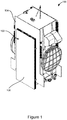
- FIGS 1-4 illustrate a general, traditional spacecraft 100 in a configuration for the transfer orbit phase of satellite insertion into a 22,000 mile geosynchronous orbit altitude.
- the spacecraft 100 comprises a pair of rigid solar arrays 102 in a stowed configuration and a pair of radiator panels 104 on opposing sides of the spacecraft 100.
- Each radiator panel 104 extends along a side of the spacecraft 100, and heat loss occurs primarily through these radiator panels 104.
- the radiator panels 104 are exposed only in an area adjacent to or surrounding a periphery of the solar array 102, which reduces, but does not prevent will heat loss. Therefore, in order to maintain a sufficient temperature of its components, the spacecraft 100 must expend battery energy to power onboard heaters and generate sufficient heat.
- the spacecraft 100 includes batteries that are specifically configured to power the bus section of the spacecraft 100 during the upper stage transfer prior to solar array deployment.
- these batteries are sized for on-orbit requirements and are well undersized to power onboard heaters without recharge during the 8-10 hours required during upper stage transfer (with launch vehicle fairing jettisoned), and the additional post-separation period prior to solar array deployment.
- the spacecraft 100 must utilize solar energy generation in order to meet the energy and heating requirements during the transfer orbit phase.
- the spacecraft can generate electrical energy to heat the spacecraft and compensate for the heat loss from the radiator panels 104.
- the electrical energy generation by the top panel 106 allows the spacecraft 100 to adequately preserve a "positive energy balance," i.e., the electrical energy generated is sufficient to recharge the spacecraft batteries and offset the electrical energy used to operate spacecraft bus equipment and heat the spacecraft 100.
- the spacecraft can generate sufficient solar electrical energy to permit activation of onboard heaters that otherwise place considerable load on the available battery power.
- the radiator panel can be covered by a thermal shield or a Transfer Orbit Thermal Shield (TOTS).
- TOTS minimizes radiative heat loss from the spacecraft radiator panels 104.
- TOTS can be used to cover all radiator panel areas, but does not totally restrict heat loss and battery heater drain.
- thermal control system that allows the generation or maintenance of heat for the spacecraft without draining electrical energy from the batteries or requiring the generation of solar electrical energy. Accordingly, spacecraft can use flexible solar arrays without the risk of exhausting available battery power and the resultant loss of the spacecraft during the upper stage launch phase.
- the thermal control system can comprise at least one extensible member coupled to the spacecraft and a thermal control panel coupled to the extensible member.
- the thermal control panel can collect and radiate solar energy toward the spacecraft radiator panels during the upper stage launch phase.
- the extensible member can be moved between a collapsed position in which a free end of the extensible member is positioned adjacent to an exposed, heat dissipating area of the spacecraft at a first distance, and an extended position in which the free end is spaced apart from the exposed area at a second distance, greater than the first distance.
- the thermal control panel can comprise one or more materials that collects incident solar energy and re-radiates it inboard toward the spacecraft radiator panels. For example, in some embodiments, the thermal control panel can collects between 50%-95% of incident solar energy.
- the thermal control panel does not need to cover all exposed radiator areas. Rather, the thermal control panel can be designed to generate enough heat for only a smaller area to be covered, thus minimizing cost and mass.
- a spacecraft 200 can comprise at least one side having an exposed area 202 capable of permitting heat transfer between the spacecraft 200 and the environment, e.g., deep space.
- the exposed area 202 can be a portion of a side panel 204.
- the side panel 204 can also be at least partially covered by one or more spacecraft components.
- the side panel 204 can be at least partially covered by a solar array panel box 210.
- the solar array panel box 210 can house a solar array, such as a flex solar array.
- the spacecraft 200 can comprise at least one movable portion or extensible member 208 that is coupled to the spacecraft 200.
- the extensible member 208 can be configured to move between a collapsed position and an extended position.
- the movable portion or extensible member 208 can be coupled to a thermal control panel or shield 212.
- the thermal control panel 212 can be actuated by movement of the extensible member 208 such that the thermal control panel 212 can be moved toward or from the spacecraft 200.
- the thermal control panel 212 can be moved between first and second positions in which the panel 212 is spaced apart from the spacecraft 200 at different distances.
- the movable portion or extensible member 208 can be a dedicated component used only for providing movement to the panel or shield 212. However, in some embodiments, the movable portion or extensible member 208 can comprise or be coupled to component of the spacecraft 200 that provides a primary usage other than as an actuating mechanism for the panel or shield 212.
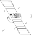
- Figures 5-8 illustrate an embodiment in which the extensible member 208 comprises or is coupled to the flex solar array 210, which is shown in the collapsed position 220.
- Figure 9 illustrates the flex solar array 210 in the extended position 222.
- the flex solar array 210 can comprise an accordion stack or accordion-fanfold configuration which can open or expand from the configuration shown in Figures 5-8 to the configuration shown in Figure 9 .
- the array 210 can comprise a boom or truss-like structure 224 configured to be coupled to the extensible member 208 to extend the array 210 outboard.
- the panel 212 can be mounted to an existing outer cover or component of a flexible solar array 210.
- the panel 212 can be coplanar with the top of the outer cover or box containing the flexible solar array.
- the panel 212 can also be mounted to one or edges of the panels of the solar array.
- the panel 212 can move along with the portion of the array to which the panel 212 is coupled (e.g., the top part of the cover). As such, as shown in Figure 9 , the panel 212 can end up at the very end of the solar array 210, spaced distally from the spacecraft.
- Figure 9 illustrates that two or more panels 212 mounted to the solar array 210 can be actuated by the solar array 210 when the solar array is deployed.
- the panel 212 in the collapsed or stowed configuration, can provide a heat radiation or generation function for the spacecraft 200.
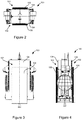
- Figure 6 illustrates direct light 240 that is incident upon the panel 212, as well as indirect light 242 that is reflected off of a portion of the spacecraft, such as the underlying side panel 204.
- This direct and indirect light 240, 242 can be absorbed by the panel 212 to heat the panel 212 to a temperature greater than that if fully exposed to deep space.
- the panel 212 can be configured to emit or radiate heat toward the underlying side panel 204. This heat radiation or generation can tend to reduce or eliminate the heater draw from the batteries due to heat loss of the spacecraft 200 from the side panel 204.
- the panel 212 in the collapsed or stowed configuration, can be mounted such that it is substantially parallel to an underlying radiator panel 204 of the spacecraft 200. However, in some embodiments, the panel 212 can be positioned skew or nonparallel relative to the underlying panel 204 or other components or portion of the spacecraft 200. In some embodiments, the panel 212 can be substantially planar. However, the panel 212 can also comprise a three-dimensional, nonplanar shape.
- the panel 212 When viewed in a side view (e.g., viewed orthogonal relative to the side panel 204), the panel 212 can comprise a periphery that is larger than or extends beyond the periphery of the side panel 204. In some embodiments, all of the periphery of the panel 212 can extend beyond or circumscribe the entire periphery of the side panel 204, thus allowing the panel 212 to be positioned over the entire exposed area 202 of the side panel 204. However, some embodiments can be configured such that only some portion or portions of the panel 212 extend beyond a portion of the side panel 204.
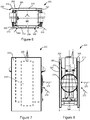
- Figure 7 illustrates depicts the panel 212 in side view being positioned over the entire exposed area 202 of the side panel 204 of the spacecraft 200
- the panel 212 can cover less than the entire exposed area 202.
- the panel 212 can comprise a perimeter, size, or shape that is about equal to the perimeter, size, or shape of the side panel 204.
- the panel 212 in side view, can cover at least about half of the exposed area 202 or at least about three-fourths of the exposed area 202.
- the panel 212 can be positioned over the entire side of the flex solar array 210. However, some embodiments can be configured such that only a portion of the side of the flex solar array 210 is covered or attached to the panel 212.
- the width of each panel of the flex solar array 210 can be between about a one-fifth to about one-half, and from about one-quarter to about one-fourth of the total width of the panel 212.
- the panel 212 can comprise a rigid or deflectable material.
- the panel 212 can comprise any of a variety of shapes.
- the periphery of the panel 212 can be rectangular, square, round, or combinations thereof.
- the panel 212 can comprise an outboard or first side or surface 260 (e.g., space facing) and an inboard or second side or surface 262 (e.g., spacecraft facing).
- the first and second sides 260, 262 can have different properties.
- the first and second sides 260, 262 can have different solar absorptivities and/or infra-red emissivities.
- the first side 260 of the panel 212 can comprise a material of high absorptivity. Further, the first side 260 can comprise a material that has a low emissivity. Additionally, in some embodiments, the first side 260 can comprise a material that has both a high absorptivity and a low emissivity. For example, in some embodiments, the first side 260 can have an absorptivity of at least about 0.40, at least about 0.50, at least about 0.60, at least about 0.70, or at least about 0.80. Further, the first side 260 can have an emissivity of less than 0.30, less than 0.20, less than 0.15, less than 0.10, or less than 0.05. In some embodiments, a ratio of absorbtance to emissivity for the first side can be at least about 2.0, at least about 3.0, at least about 5.0, at least about 8.0, or at least about 11.0.
- the first side 260 may be constructed, for example, of Kapton, titanium, nickel, beryllium, and their derivatives, such as titanium foil, bare titanium, anodized titanium, bare beryllium, chromate black nickel, or other advanced solar selective surface material or combinations thereof.
- the second side 262 can comprise a material having a high absorptivity. However, the second side 262 can also comprise a material having a high emissivity. In some embodiments, the second side 262 can comprise a material having a high absorptivity and a high emissivity. For example, in some embodiments, the second side 262 can have an absorptivity of at least about 0.70, at least about 0.80, at least about 0.85, at least about 0.90, or at least about 0.95. Furthermore, the second side 262 can have an emissivity of at least about 0.60, at least about 0.70, at least about 0.80, at least about 0.85, or at least about 0.90.
- the second side 262 can comprise a paint (such as a black paint), Kapton tape or film, metal deposits (such as a nickel deposit, a titanium deposit, a chromium deposit, etc.), chemical conversion coating, or their derivatives or combinations thereof.
- the second side 262 can be configured to radiate to an underlying high emissivity optical solar reflector radiator coating. With a high emissivity, the second side 262 can radiate heat from absorbed solar rays toward the spacecraft and, particularly, the side panels 204 of the spacecraft 200.
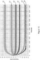
- Figure 10 depicts a graph having example spacecraft radiator panel temperature profiles for various outboard materials and light incident angles, according to some embodiments.
- the spacecraft is assumed to be rotating about its nadir-zenith axis in a passive thermal control mode as is typical during transfer orbit.
- the light incident angles are demonstrated as 0° and 60° relative to the spacecraft rotation axis, as illustrated in Figures 7-8 .
- the graph of Figure 10 illustrates that the panel 212 can achieve various ranges of temperatures over time based on the material and son angle used for the outboard or first side 260 of the panel 212.
- line 300 illustrates temperature ranges for anodized titanium at a 0° angle.
- Line 302 illustrates temperature ranges for anodized titanium at a 60° angle.
- line 310 illustrates temperature ranges for bare titanium at a 0° angle.
- Line 312 illustrates temperature ranges for bare titanium at a 60° angle.
- line 320 illustrates temperature ranges for aluminized Kapton at a 0° angle.
- Line 322 illustrates temperature ranges for aluminized Kapton at a 60° angle.
- Aluminized Kapton is conventionally used for TOTS configurations and the line 322 results illustrate that heater power is required to maintain required minimum operational temperature limits at the 2.3 hour point, well before the end of transfer orbit, or when solar array deployment occurs.
- the other two sample solar selective materials represented by lines 300, 302 and 310, 312 are able to maintain panel 202 temperatures above heater range, thus avoiding adverse battery heater drain.
- the panel 212 can comprise a thin sheet of material.
- the panel can have a thickness of between about 2 mm and about 10 mm.
- the panel can have a thickness of between about 3 mm and about 6 mm.
- the panel can have a thickness of between about 3 mm and about 4 mm, about 3 mm and about 5 mm, about 4 mm and about 5 mm, or other such ranges.
- a radiator panel 204 on one side of the spacecraft 200 can be 8' wide by 20' tall, with an undeployed flexible solar array 210 occupying a 3' by 15' area above the radiator panel.
- the exposed portions of the radiator panel 204 to the side and above the undeployed solar array 210 will continue to lose or radiate heat from the systems internal the spacecraft 200.
- onboard heaters may be activated and drain power from the batteries.
- the panel 212 can cover the exposed areas (e.g., 2-3' on each side), collects solar energy using the previously described outboard facing surface 260, and re-radiates the heat inward toward the exposed portions 202 of the radiator panels 204 to prevent heat loss and avoid battery electrical drain associated with radiator panel electrical heaters.
- duration of transfer orbit may be two or more weeks, whereas, the battery, without electrical recharge capability would last only about 8 hours.
- implementation of some embodiments disclosed herein can eliminate the need for heater power usage prior to solar array deployment and extend battery life to >20 hours, thus enabling acceptable operation prior to deployment of flex solar array 210.
- angles formed between the referenced components can be greater or less than 90 degrees in some embodiments.
- the phrase "at least one of' preceding a series of items, with the term “and” or “or” to separate any of the items, modifies the list as a whole, rather than each member of the list (i.e., each item).
- phrases “at least one of A, B, and C” or “at least one of A, B, or C” each refer to only A, only B, or only C; any combination of A, B, and C; and/or at least one of each of A, B, and C.
- a phrase such as an "aspect” does not imply that such aspect is essential to the subject technology or that such aspect applies to all configurations of the subject technology.
- a disclosure relating to an aspect may apply to all configurations, or one or more configurations.
- An aspect may provide one or more examples.
- a phrase such as an aspect may refer to one or more aspects and vice versa.
- a phrase such as an "embodiment” does not imply that such embodiment is essential to the subject technology or that such embodiment applies to all configurations of the subject technology.
- a disclosure relating to an embodiment may apply to all embodiments, or one or more embodiments.
- An embodiment may provide one or more examples.
- a phrase such an embodiment may refer to one or more embodiments and vice versa.
- a phrase such as a "configuration” does not imply that such configuration is essential to the subject technology or that such configuration applies to all configurations of the subject technology.
- a disclosure relating to a configuration may apply to all configurations, or one or more configurations.
- a configuration may provide one or more examples.
- a phrase such a configuration may refer to one or more configurations and vice versa.
Landscapes
- Engineering & Computer Science (AREA)
- Remote Sensing (AREA)
- Aviation & Aerospace Engineering (AREA)
- Life Sciences & Earth Sciences (AREA)
- General Health & Medical Sciences (AREA)
- Health & Medical Sciences (AREA)
- Environmental Sciences (AREA)
- Environmental & Geological Engineering (AREA)
- Biodiversity & Conservation Biology (AREA)
- Toxicology (AREA)
- Sustainable Development (AREA)
- Photovoltaic Devices (AREA)
- Housing For Livestock And Birds (AREA)
- Physics & Mathematics (AREA)
- Thermal Sciences (AREA)
- Critical Care (AREA)
- Emergency Medicine (AREA)
Claims (13)
- Astronef (200), comprenant :un côté présentant une zone exposée (202) capable de permettre un transfert de chaleur entre l'astronef (200) et l'espace lointain ;au moins un élément extensible (208) couplé à l'astronef (200), l'au moins un élément extensible (208) étant mobile entre une position repliée dans laquelle une extrémité libre de l'élément extensible (208) est positionnée de manière adjacente à la zone exposée (202) à une première distance et une position étendue dans laquelle l'extrémité libre est espacée de la zone exposée (202) à une deuxième distance supérieure à la première distance ; etun panneau de commande thermique (212) comprenant un premier et un deuxième côté (260, 262), le premier côté (260) ayant une émissivité inférieure à une émissivité du deuxième côté (262), le premier côté (260) ayant une absorptivité d'au moins 0,50 et une émissivité d'au moins 0,20, le deuxième côté (262) ayant une absorptivité d'au moins 0,80 et une émissivité d'au moins 0,80, le panneau (212) étant couplé à l'extrémité libre de l'élément extensible (208), le deuxième côté (262) faisant face à la zone exposée (202) lorsque l'élément extensible (208) est dans la position repliée ;sachant que dans la position repliée, le panneau (212) est configuré pour absorber de la lumière ambiante et émettre de la chaleur vers la zone exposée (202) en minimisant ainsi une perte de chaleur depuis le côté astronef, et sachant que dans la position étendue, un transfert de chaleur depuis le côté astronef n'est pas sensiblement restreint par le premier et le deuxième côté (260, 262) du panneau (212).
- L'astronef (200) de la revendication 1, sachant que l'au moins un élément extensible (208) est couplé au côté astronef.
- L'astronef (200) de la revendication 1, sachant que l'élément extensible (208) comprend un réseau solaire (210) flexible extensible, le réseau solaire (210) comprenant un panneau supérieur présentant des surfaces intérieure et extérieure, la surface intérieure comprenant au moins une cellule solaire, sachant que le panneau est couplé à la surface extérieure.
- L'astronef (200) de la revendication 1, comprenant en outre un dispositif solaire, et sachant que dans la configuration repliée, des cellules solaires du dispositif solaire ne sont pas exposées à la lumière ambiante.
- L'astronef (200) de la revendication 4, sachant que le dispositif solaire comprend un réseau solaire (210) flexible extensible couplé au côté astronef, le panneau de commande thermique (212) étant couplé à une surface extérieure d'un panneau supérieur du réseau solaire (210).
- L'astronef (200) de la revendication 1, sachant que dans la position étendue, le deuxième côté (262) du panneau de commande thermique (212) est tourné du côté opposé à la zone exposée (202).
- L'astronef (200) de la revendication 1, sachant que le panneau de commande thermique (212) comprend :
un corps de panneau qui comprend le premier et le deuxième côté (260, 262). - L'astronef (200) de la revendication 7, sachant que le corps de panneau comprend du Kapton.
- L'astronef (200) de la revendication 7, sachant que le corps de panneau comprend un matériau déposé sur le premier côté (260).
- L'astronef (200) de la revendication 7, sachant que le premier ou deuxième côté (262) comprend un revêtement de conversion chimique.
- L'astronef (200) de la revendication 7, sachant que le corps de panneau comprend au moins deux matériaux.
- L'astronef (200) de la revendication 11, sachant que le premier côté (260) comprend du titane nu, du titane anodisé, du béryllium nu, ou du nickel noir de chromate.
- L'astronef (200) de la revendication 11, sachant que le deuxième côté (262) comprend de la peinture noire, un ruban de Kapton, un film de Kapton, ou un revêtement de conversion chimique.
Applications Claiming Priority (3)
| Application Number | Priority Date | Filing Date | Title |
|---|---|---|---|
| US201361810225P | 2013-04-09 | 2013-04-09 | |
| US14/197,033 US9352855B2 (en) | 2013-04-09 | 2014-03-04 | Heat generating transfer orbit shield |
| PCT/US2014/033285 WO2014168923A2 (fr) | 2013-04-09 | 2014-04-08 | Bouclier d'orbite de transfert de génération thermique |
Publications (3)
| Publication Number | Publication Date |
|---|---|
| EP2983992A2 EP2983992A2 (fr) | 2016-02-17 |
| EP2983992A4 EP2983992A4 (fr) | 2016-11-30 |
| EP2983992B1 true EP2983992B1 (fr) | 2020-03-18 |
Family
ID=51653787
Family Applications (1)
| Application Number | Title | Priority Date | Filing Date |
|---|---|---|---|
| EP14782713.3A Active EP2983992B1 (fr) | 2013-04-09 | 2014-04-08 | Bouclier d'orbite de transfert de génération thermique |
Country Status (5)
| Country | Link |
|---|---|
| US (1) | US9352855B2 (fr) |
| EP (1) | EP2983992B1 (fr) |
| JP (1) | JP6643224B2 (fr) |
| ES (1) | ES2780851T3 (fr) |
| WO (1) | WO2014168923A2 (fr) |
Cited By (1)
| Publication number | Priority date | Publication date | Assignee | Title |
|---|---|---|---|---|
| CN112491350A (zh) * | 2020-11-27 | 2021-03-12 | 东南大学 | 一种空间薄膜电池阵的张拉装置 |
Families Citing this family (18)
| Publication number | Priority date | Publication date | Assignee | Title |
|---|---|---|---|---|
| US9352855B2 (en) * | 2013-04-09 | 2016-05-31 | Lockheed Martin Corporation | Heat generating transfer orbit shield |
| FR3030457B1 (fr) * | 2014-12-17 | 2018-06-01 | Airbus Defence And Space Sas | Engin spatial |
| FR3031969B1 (fr) * | 2015-01-27 | 2017-01-27 | Airbus Defence & Space Sas | Satellite artificiel et procede de remplissage d'un reservoir de gaz propulsif dudit satellite artificiel |
| EP3259189B1 (fr) * | 2015-06-02 | 2018-07-18 | Airbus Defence and Space SAS | Satellite artificiel |
| FR3040045B1 (fr) * | 2015-08-10 | 2017-09-08 | Airbus Defence & Space Sas | Satellite artificiel |
| FR3041608B1 (fr) * | 2015-09-25 | 2018-04-13 | Thales Sa | Ensemble deployable |
| NL2016677B1 (en) | 2016-04-26 | 2017-11-07 | Airbus Defence And Space Netherlands B V | Solar Panel and Flexible Radiator for a Spacecraft. |
| FR3051443A1 (fr) * | 2016-05-23 | 2017-11-24 | Airbus Defence & Space Sas | Engin spatial |
| CN105966640B (zh) * | 2016-06-15 | 2018-03-16 | 哈尔滨工业大学 | 一种可重复变构型桁架式航天器结构 |
| EP3556666B1 (fr) | 2016-12-19 | 2023-03-08 | Mitsubishi Electric Corporation | Radiateur déployable |
| EP3619116A4 (fr) * | 2017-04-21 | 2021-04-28 | Lockheed Martin Corporation | Réseau modulaire multi-mission |
| WO2019204463A1 (fr) * | 2018-04-17 | 2019-10-24 | Raytheon Company | Structures thermiquement améliorées et déployables |
| CN109625343B (zh) * | 2018-12-10 | 2022-03-29 | 上海卫星装备研究所 | 边缘补偿式外热流模拟装置 |
| CN111071499B (zh) * | 2019-12-31 | 2021-06-22 | 中国科学院空间应用工程与技术中心 | 一种材料舱外暴露装置 |
| US11760510B1 (en) * | 2020-03-09 | 2023-09-19 | Maxar Space Llc | Spacecraft design with semi-rigid solar array |
| US20240014894A1 (en) | 2020-09-28 | 2024-01-11 | Mitsubishi Electric Corporation | Satellite watching system, satellite information transmission system, ground equipment, communication satellite, monitoring system, constituent satellite, artificial satellite, communication satellite constellation, satellite constellation, and satellite |
| DE102021102331B4 (de) | 2021-02-02 | 2023-04-06 | Deutsches Zentrum für Luft- und Raumfahrt e.V. | Verfahren zur Thermalkontrolle und Raumfahrtobjekt |
| CN114039531B (zh) * | 2022-01-10 | 2022-03-29 | 南通快猛电源有限公司 | 一种车用蓄电池太阳能充电装置 |
Family Cites Families (33)
| Publication number | Priority date | Publication date | Assignee | Title |
|---|---|---|---|---|
| US3653942A (en) * | 1970-04-28 | 1972-04-04 | Us Air Force | Method of controlling temperature distribution of a spacecraft |
| US3768754A (en) * | 1971-01-26 | 1973-10-30 | Org Europ De Rech Spatiales | Louver system with sandwich type blades |
| US3817320A (en) * | 1971-03-02 | 1974-06-18 | Rca Corp | Passive cooler |
| DE2350972A1 (de) * | 1973-10-11 | 1975-04-24 | Bosch Gmbh Robert | Temperaturregulierende oberflaeche |
| JPS60206159A (ja) * | 1984-03-30 | 1985-10-17 | Toshiba Corp | 太陽電池パネル装置 |
| JPS61196899A (ja) * | 1985-02-26 | 1986-09-01 | 三菱電機株式会社 | 人工衛星 |
| JPS63145020A (ja) * | 1986-12-09 | 1988-06-17 | 三菱電機株式会社 | 宇宙飛翔体熱移動・熱制御積層複合材料 |
| JPH0365498A (ja) * | 1989-08-02 | 1991-03-20 | Toshiba Corp | 熱制御材料及びその製造方法 |
| JPH03114999A (ja) * | 1989-09-29 | 1991-05-16 | Toshiba Corp | 宇宙航行体の熱制御装置 |
| US5372183A (en) * | 1991-08-22 | 1994-12-13 | Strickberger; Harold P. | Thermal control arrangements for a geosynchronous spacecraft |
| US5337980A (en) * | 1992-09-21 | 1994-08-16 | General Electric Co. | Spacecraft-to-launch-vehicle transition |
| US5806800A (en) * | 1995-12-22 | 1998-09-15 | Caplin; Glenn N. | Dual function deployable radiator cover |
| US5732765A (en) * | 1995-12-22 | 1998-03-31 | Hughes Electronics | Adjustable heat rejection system |
| US5823477A (en) * | 1995-12-22 | 1998-10-20 | Hughes Electronics Corporation | Device and method for minimizing radiator area required for heat dissipation on a spacecraft |
| US5884868A (en) * | 1997-03-18 | 1999-03-23 | Hughes Electronics Corporation | Radiator using thermal control coating |
| US5927654A (en) * | 1997-05-16 | 1999-07-27 | Lockheed Martin Corp. | Spacecraft with active antenna array protected against temperature extremes |
| US6073887A (en) * | 1997-07-16 | 2000-06-13 | Space Systems/Loral, Inc. | High power spacecraft with full utilization of all spacecraft surfaces |
| US6102339A (en) * | 1998-04-17 | 2000-08-15 | Turbosat Technology, Inc. | Sun-synchronous sun ray blocking device for use in a spacecraft having a directionally controlled main body |
| US6073888A (en) * | 1998-12-02 | 2000-06-13 | Loral Space & Communications, Ltd. | Sequenced heat rejection for body stabilized geosynchronous satellites |
| US6394395B1 (en) * | 2000-03-15 | 2002-05-28 | Lockheed Martin Corporation | Combination solar array assembly and antenna for a satellite |
| FR2823182B1 (fr) * | 2001-04-05 | 2004-06-04 | Cit Alcatel | Radiateur deployable pour engin spatial |
| US6921050B2 (en) * | 2003-01-17 | 2005-07-26 | Northrop Grumman Corporation | Solar torque control using thin film directionally reflective, emissive, absorptive and transmissive surfaces |
| FR2889205B1 (fr) * | 2005-07-26 | 2007-11-30 | Eads Astrium Sas Soc Par Actio | Revetement pour dispositif externe de controle thermo-optique d'elements de vehicules spatiaux, son procede de formation par micro-arcs en milieu ionise, et dispositif recouvert de ce revetement |
| US7874520B2 (en) * | 2006-03-21 | 2011-01-25 | Lockheed Martin Corporation | Satellite with deployable, articulatable thermal radiators |
| JP2008265522A (ja) | 2007-04-20 | 2008-11-06 | Japan Aerospace Exploration Agency | 熱制御装置 |
| US7967256B2 (en) * | 2007-05-08 | 2011-06-28 | Lockheed Martin Corporation | Spacecraft battery thermal management system |
| US8460777B2 (en) * | 2008-10-07 | 2013-06-11 | Alliant Techsystems Inc. | Multifunctional radiation-hardened laminate |
| EP2411283A1 (fr) * | 2009-03-24 | 2012-02-01 | Lockheed Martin Corporation | Système de dissipation de chaleur pour vaisseau spatial |
| FR2963981A1 (fr) * | 2010-08-20 | 2012-02-24 | Astrium Sas | Coupole absorbante pour tube a collecteur rayonnant |
| FR2969985B1 (fr) * | 2010-12-30 | 2016-09-09 | Thales Sa | Générateur solaire plan deroulable |
| US8714492B2 (en) * | 2012-02-07 | 2014-05-06 | Lockheed Martin Corporation | Non-interfering deployable radiator arrangement for geo spacecraft |
| US8967547B2 (en) * | 2013-02-12 | 2015-03-03 | Lockheed Martin Corporation | Spacecraft east-west radiator assembly |
| US9352855B2 (en) * | 2013-04-09 | 2016-05-31 | Lockheed Martin Corporation | Heat generating transfer orbit shield |
-
2014
- 2014-03-04 US US14/197,033 patent/US9352855B2/en active Active
- 2014-04-08 JP JP2016507603A patent/JP6643224B2/ja active Active
- 2014-04-08 WO PCT/US2014/033285 patent/WO2014168923A2/fr active Application Filing
- 2014-04-08 ES ES14782713T patent/ES2780851T3/es active Active
- 2014-04-08 EP EP14782713.3A patent/EP2983992B1/fr active Active
Non-Patent Citations (1)
| Title |
|---|
| None * |
Cited By (1)
| Publication number | Priority date | Publication date | Assignee | Title |
|---|---|---|---|---|
| CN112491350A (zh) * | 2020-11-27 | 2021-03-12 | 东南大学 | 一种空间薄膜电池阵的张拉装置 |
Also Published As
| Publication number | Publication date |
|---|---|
| US9352855B2 (en) | 2016-05-31 |
| ES2780851T3 (es) | 2020-08-27 |
| WO2014168923A3 (fr) | 2014-12-18 |
| WO2014168923A2 (fr) | 2014-10-16 |
| EP2983992A4 (fr) | 2016-11-30 |
| US20140299714A1 (en) | 2014-10-09 |
| EP2983992A2 (fr) | 2016-02-17 |
| JP2016521225A (ja) | 2016-07-21 |
| JP6643224B2 (ja) | 2020-02-12 |
Similar Documents
| Publication | Publication Date | Title |
|---|---|---|
| EP2983992B1 (fr) | Bouclier d'orbite de transfert de génération thermique | |
| US10340843B2 (en) | Solar panel with flexible optical elements | |
| US9004410B1 (en) | Deployable boom for collecting electromagnetic energy | |
| US6394395B1 (en) | Combination solar array assembly and antenna for a satellite | |
| JP6640116B2 (ja) | 大規模宇宙太陽光発電所:効率的発電タイル | |
| US10737808B2 (en) | Solar panel and flexible radiator for a spacecraft | |
| US10992253B2 (en) | Compactable power generation arrays | |
| Kang et al. | On-orbit thermal design and validation of 1 U standardized CubeSat of STEP cube lab | |
| EP0822139B1 (fr) | Radiateurs déployables pour engins spatiaux | |
| US9276148B2 (en) | Thermally efficient power conversion modules for space solar power | |
| US8550407B2 (en) | Large rigid deployable structures and method of deploying and locking such structures | |
| US8960608B2 (en) | Deployable radiator having an increased view factor | |
| EP1174342A1 (fr) | Concentrateur solaire | |
| US9868551B2 (en) | Passive thermal system comprising combined heat pipe and phase change material and satellites incorporating same | |
| US10207824B2 (en) | Radiator deployable for a satellite stabilized on three axes | |
| WO2017027615A1 (fr) | Réseaux de génération d'énergie compactables | |
| Fatemi et al. | Qualification and production of Emcore ZTJ solar panels for space missions | |
| EP2956364B1 (fr) | Radiateur déployable à facteur de forme accru | |
| Stern et al. | Composite beam roll-out array-a multifunctional deployable structure for space power generation | |
| Simburger et al. | Multifunctional structures for the PowerSphere concept | |
| Landis et al. | Solar power system design for the solar probe+ mission | |
| Ogawa et al. | BepiColombo/MMO thermal control system | |
| Stramaccioni et al. | XMM-NEWTON thermal design and in-orbit performance | |
| Ohnishi et al. | Thermal Design of the MUSES-B Spacecraft | |
| Ercol et al. | The MESSENGER spacecraft power system: thermal performance through the first mercury flyby |
Legal Events
| Date | Code | Title | Description |
|---|---|---|---|
| PUAI | Public reference made under article 153(3) epc to a published international application that has entered the european phase |
Free format text: ORIGINAL CODE: 0009012 |
|
| 17P | Request for examination filed |
Effective date: 20151013 |
|
| AK | Designated contracting states |
Kind code of ref document: A2 Designated state(s): AL AT BE BG CH CY CZ DE DK EE ES FI FR GB GR HR HU IE IS IT LI LT LU LV MC MK MT NL NO PL PT RO RS SE SI SK SM TR |
|
| AX | Request for extension of the european patent |
Extension state: BA ME |
|
| DAX | Request for extension of the european patent (deleted) | ||
| A4 | Supplementary search report drawn up and despatched |
Effective date: 20161103 |
|
| RIC1 | Information provided on ipc code assigned before grant |
Ipc: B64G 1/22 20060101ALN20161027BHEP Ipc: B64G 1/44 20060101AFI20161027BHEP Ipc: B64G 1/50 20060101ALI20161027BHEP |
|
| STAA | Information on the status of an ep patent application or granted ep patent |
Free format text: STATUS: EXAMINATION IS IN PROGRESS |
|
| 17Q | First examination report despatched |
Effective date: 20190103 |
|
| REG | Reference to a national code |
Ref country code: DE Ref legal event code: R079 Ref document number: 602014062548 Country of ref document: DE Free format text: PREVIOUS MAIN CLASS: B64G0001580000 Ipc: B64G0001440000 |
|
| GRAP | Despatch of communication of intention to grant a patent |
Free format text: ORIGINAL CODE: EPIDOSNIGR1 |
|
| STAA | Information on the status of an ep patent application or granted ep patent |
Free format text: STATUS: GRANT OF PATENT IS INTENDED |
|
| RIC1 | Information provided on ipc code assigned before grant |
Ipc: B64G 1/44 20060101AFI20190828BHEP Ipc: B64G 1/22 20060101ALN20190828BHEP Ipc: B64G 1/50 20060101ALI20190828BHEP |
|
| INTG | Intention to grant announced |
Effective date: 20191002 |
|
| GRAS | Grant fee paid |
Free format text: ORIGINAL CODE: EPIDOSNIGR3 |
|
| GRAA | (expected) grant |
Free format text: ORIGINAL CODE: 0009210 |
|
| STAA | Information on the status of an ep patent application or granted ep patent |
Free format text: STATUS: THE PATENT HAS BEEN GRANTED |
|
| AK | Designated contracting states |
Kind code of ref document: B1 Designated state(s): AL AT BE BG CH CY CZ DE DK EE ES FI FR GB GR HR HU IE IS IT LI LT LU LV MC MK MT NL NO PL PT RO RS SE SI SK SM TR |
|
| REG | Reference to a national code |
Ref country code: GB Ref legal event code: FG4D |
|
| REG | Reference to a national code |
Ref country code: DE Ref legal event code: R096 Ref document number: 602014062548 Country of ref document: DE |
|
| REG | Reference to a national code |
Ref country code: AT Ref legal event code: REF Ref document number: 1245655 Country of ref document: AT Kind code of ref document: T Effective date: 20200415 Ref country code: IE Ref legal event code: FG4D |
|
| PG25 | Lapsed in a contracting state [announced via postgrant information from national office to epo] |
Ref country code: NO Free format text: LAPSE BECAUSE OF FAILURE TO SUBMIT A TRANSLATION OF THE DESCRIPTION OR TO PAY THE FEE WITHIN THE PRESCRIBED TIME-LIMIT Effective date: 20200618 Ref country code: FI Free format text: LAPSE BECAUSE OF FAILURE TO SUBMIT A TRANSLATION OF THE DESCRIPTION OR TO PAY THE FEE WITHIN THE PRESCRIBED TIME-LIMIT Effective date: 20200318 Ref country code: RS Free format text: LAPSE BECAUSE OF FAILURE TO SUBMIT A TRANSLATION OF THE DESCRIPTION OR TO PAY THE FEE WITHIN THE PRESCRIBED TIME-LIMIT Effective date: 20200318 |
|
| REG | Reference to a national code |
Ref country code: NL Ref legal event code: MP Effective date: 20200318 |
|
| REG | Reference to a national code |
Ref country code: ES Ref legal event code: FG2A Ref document number: 2780851 Country of ref document: ES Kind code of ref document: T3 Effective date: 20200827 |
|
| PG25 | Lapsed in a contracting state [announced via postgrant information from national office to epo] |
Ref country code: BG Free format text: LAPSE BECAUSE OF FAILURE TO SUBMIT A TRANSLATION OF THE DESCRIPTION OR TO PAY THE FEE WITHIN THE PRESCRIBED TIME-LIMIT Effective date: 20200618 Ref country code: GR Free format text: LAPSE BECAUSE OF FAILURE TO SUBMIT A TRANSLATION OF THE DESCRIPTION OR TO PAY THE FEE WITHIN THE PRESCRIBED TIME-LIMIT Effective date: 20200619 Ref country code: SE Free format text: LAPSE BECAUSE OF FAILURE TO SUBMIT A TRANSLATION OF THE DESCRIPTION OR TO PAY THE FEE WITHIN THE PRESCRIBED TIME-LIMIT Effective date: 20200318 Ref country code: LV Free format text: LAPSE BECAUSE OF FAILURE TO SUBMIT A TRANSLATION OF THE DESCRIPTION OR TO PAY THE FEE WITHIN THE PRESCRIBED TIME-LIMIT Effective date: 20200318 Ref country code: HR Free format text: LAPSE BECAUSE OF FAILURE TO SUBMIT A TRANSLATION OF THE DESCRIPTION OR TO PAY THE FEE WITHIN THE PRESCRIBED TIME-LIMIT Effective date: 20200318 |
|
| REG | Reference to a national code |
Ref country code: LT Ref legal event code: MG4D |
|
| PG25 | Lapsed in a contracting state [announced via postgrant information from national office to epo] |
Ref country code: NL Free format text: LAPSE BECAUSE OF FAILURE TO SUBMIT A TRANSLATION OF THE DESCRIPTION OR TO PAY THE FEE WITHIN THE PRESCRIBED TIME-LIMIT Effective date: 20200318 |
|
| PG25 | Lapsed in a contracting state [announced via postgrant information from national office to epo] |
Ref country code: IS Free format text: LAPSE BECAUSE OF FAILURE TO SUBMIT A TRANSLATION OF THE DESCRIPTION OR TO PAY THE FEE WITHIN THE PRESCRIBED TIME-LIMIT Effective date: 20200718 Ref country code: SK Free format text: LAPSE BECAUSE OF FAILURE TO SUBMIT A TRANSLATION OF THE DESCRIPTION OR TO PAY THE FEE WITHIN THE PRESCRIBED TIME-LIMIT Effective date: 20200318 Ref country code: RO Free format text: LAPSE BECAUSE OF FAILURE TO SUBMIT A TRANSLATION OF THE DESCRIPTION OR TO PAY THE FEE WITHIN THE PRESCRIBED TIME-LIMIT Effective date: 20200318 Ref country code: LT Free format text: LAPSE BECAUSE OF FAILURE TO SUBMIT A TRANSLATION OF THE DESCRIPTION OR TO PAY THE FEE WITHIN THE PRESCRIBED TIME-LIMIT Effective date: 20200318 Ref country code: CZ Free format text: LAPSE BECAUSE OF FAILURE TO SUBMIT A TRANSLATION OF THE DESCRIPTION OR TO PAY THE FEE WITHIN THE PRESCRIBED TIME-LIMIT Effective date: 20200318 Ref country code: SM Free format text: LAPSE BECAUSE OF FAILURE TO SUBMIT A TRANSLATION OF THE DESCRIPTION OR TO PAY THE FEE WITHIN THE PRESCRIBED TIME-LIMIT Effective date: 20200318 Ref country code: EE Free format text: LAPSE BECAUSE OF FAILURE TO SUBMIT A TRANSLATION OF THE DESCRIPTION OR TO PAY THE FEE WITHIN THE PRESCRIBED TIME-LIMIT Effective date: 20200318 Ref country code: PT Free format text: LAPSE BECAUSE OF FAILURE TO SUBMIT A TRANSLATION OF THE DESCRIPTION OR TO PAY THE FEE WITHIN THE PRESCRIBED TIME-LIMIT Effective date: 20200812 |
|
| REG | Reference to a national code |
Ref country code: AT Ref legal event code: MK05 Ref document number: 1245655 Country of ref document: AT Kind code of ref document: T Effective date: 20200318 |
|
| REG | Reference to a national code |
Ref country code: CH Ref legal event code: PL |
|
| REG | Reference to a national code |
Ref country code: DE Ref legal event code: R097 Ref document number: 602014062548 Country of ref document: DE |
|
| PG25 | Lapsed in a contracting state [announced via postgrant information from national office to epo] |
Ref country code: MC Free format text: LAPSE BECAUSE OF FAILURE TO SUBMIT A TRANSLATION OF THE DESCRIPTION OR TO PAY THE FEE WITHIN THE PRESCRIBED TIME-LIMIT Effective date: 20200318 |
|
| PLBE | No opposition filed within time limit |
Free format text: ORIGINAL CODE: 0009261 |
|
| STAA | Information on the status of an ep patent application or granted ep patent |
Free format text: STATUS: NO OPPOSITION FILED WITHIN TIME LIMIT |
|
| PG25 | Lapsed in a contracting state [announced via postgrant information from national office to epo] |
Ref country code: IT Free format text: LAPSE BECAUSE OF FAILURE TO SUBMIT A TRANSLATION OF THE DESCRIPTION OR TO PAY THE FEE WITHIN THE PRESCRIBED TIME-LIMIT Effective date: 20200318 Ref country code: LU Free format text: LAPSE BECAUSE OF NON-PAYMENT OF DUE FEES Effective date: 20200408 Ref country code: LI Free format text: LAPSE BECAUSE OF NON-PAYMENT OF DUE FEES Effective date: 20200430 Ref country code: DK Free format text: LAPSE BECAUSE OF FAILURE TO SUBMIT A TRANSLATION OF THE DESCRIPTION OR TO PAY THE FEE WITHIN THE PRESCRIBED TIME-LIMIT Effective date: 20200318 Ref country code: AT Free format text: LAPSE BECAUSE OF FAILURE TO SUBMIT A TRANSLATION OF THE DESCRIPTION OR TO PAY THE FEE WITHIN THE PRESCRIBED TIME-LIMIT Effective date: 20200318 Ref country code: CH Free format text: LAPSE BECAUSE OF NON-PAYMENT OF DUE FEES Effective date: 20200430 |
|
| REG | Reference to a national code |
Ref country code: BE Ref legal event code: MM Effective date: 20200430 |
|
| 26N | No opposition filed |
Effective date: 20201221 |
|
| PG25 | Lapsed in a contracting state [announced via postgrant information from national office to epo] |
Ref country code: PL Free format text: LAPSE BECAUSE OF FAILURE TO SUBMIT A TRANSLATION OF THE DESCRIPTION OR TO PAY THE FEE WITHIN THE PRESCRIBED TIME-LIMIT Effective date: 20200318 Ref country code: BE Free format text: LAPSE BECAUSE OF NON-PAYMENT OF DUE FEES Effective date: 20200430 |
|
| PG25 | Lapsed in a contracting state [announced via postgrant information from national office to epo] |
Ref country code: IE Free format text: LAPSE BECAUSE OF NON-PAYMENT OF DUE FEES Effective date: 20200408 |
|
| PG25 | Lapsed in a contracting state [announced via postgrant information from national office to epo] |
Ref country code: SI Free format text: LAPSE BECAUSE OF FAILURE TO SUBMIT A TRANSLATION OF THE DESCRIPTION OR TO PAY THE FEE WITHIN THE PRESCRIBED TIME-LIMIT Effective date: 20200318 |
|
| PG25 | Lapsed in a contracting state [announced via postgrant information from national office to epo] |
Ref country code: TR Free format text: LAPSE BECAUSE OF FAILURE TO SUBMIT A TRANSLATION OF THE DESCRIPTION OR TO PAY THE FEE WITHIN THE PRESCRIBED TIME-LIMIT Effective date: 20200318 Ref country code: MT Free format text: LAPSE BECAUSE OF FAILURE TO SUBMIT A TRANSLATION OF THE DESCRIPTION OR TO PAY THE FEE WITHIN THE PRESCRIBED TIME-LIMIT Effective date: 20200318 Ref country code: CY Free format text: LAPSE BECAUSE OF FAILURE TO SUBMIT A TRANSLATION OF THE DESCRIPTION OR TO PAY THE FEE WITHIN THE PRESCRIBED TIME-LIMIT Effective date: 20200318 |
|
| PG25 | Lapsed in a contracting state [announced via postgrant information from national office to epo] |
Ref country code: MK Free format text: LAPSE BECAUSE OF FAILURE TO SUBMIT A TRANSLATION OF THE DESCRIPTION OR TO PAY THE FEE WITHIN THE PRESCRIBED TIME-LIMIT Effective date: 20200318 Ref country code: AL Free format text: LAPSE BECAUSE OF FAILURE TO SUBMIT A TRANSLATION OF THE DESCRIPTION OR TO PAY THE FEE WITHIN THE PRESCRIBED TIME-LIMIT Effective date: 20200318 |
|
| PGFP | Annual fee paid to national office [announced via postgrant information from national office to epo] |
Ref country code: FR Payment date: 20230425 Year of fee payment: 10 Ref country code: ES Payment date: 20230503 Year of fee payment: 10 Ref country code: DE Payment date: 20230427 Year of fee payment: 10 |
|
| PGFP | Annual fee paid to national office [announced via postgrant information from national office to epo] |
Ref country code: GB Payment date: 20230427 Year of fee payment: 10 |