EP2983263A1 - Current-limiting/flow control device - Google Patents
Current-limiting/flow control device Download PDFInfo
- Publication number
- EP2983263A1 EP2983263A1 EP14779757.5A EP14779757A EP2983263A1 EP 2983263 A1 EP2983263 A1 EP 2983263A1 EP 14779757 A EP14779757 A EP 14779757A EP 2983263 A1 EP2983263 A1 EP 2983263A1
- Authority
- EP
- European Patent Office
- Prior art keywords
- current
- limiting
- power
- flow control
- control device
- Prior art date
- Legal status (The legal status is an assumption and is not a legal conclusion. Google has not performed a legal analysis and makes no representation as to the accuracy of the status listed.)
- Granted
Links
- 239000003990 capacitor Substances 0.000 claims abstract description 42
- 239000002887 superconductor Substances 0.000 claims abstract description 12
- 230000007704 transition Effects 0.000 abstract description 6
- 230000005540 biological transmission Effects 0.000 description 27
- 238000004088 simulation Methods 0.000 description 15
- 230000001939 inductive effect Effects 0.000 description 12
- 230000000694 effects Effects 0.000 description 8
- 238000011084 recovery Methods 0.000 description 4
- 230000008859 change Effects 0.000 description 3
- 238000010586 diagram Methods 0.000 description 3
- 238000011161 development Methods 0.000 description 2
- 238000009434 installation Methods 0.000 description 2
- 230000001052 transient effect Effects 0.000 description 2
- 238000012795 verification Methods 0.000 description 2
- 230000003247 decreasing effect Effects 0.000 description 1
- 238000002474 experimental method Methods 0.000 description 1
- 238000010304 firing Methods 0.000 description 1
- 238000003780 insertion Methods 0.000 description 1
- 230000037431 insertion Effects 0.000 description 1
- 238000012423 maintenance Methods 0.000 description 1
- 238000000034 method Methods 0.000 description 1
- 238000012986 modification Methods 0.000 description 1
- 230000004048 modification Effects 0.000 description 1
- 230000008569 process Effects 0.000 description 1
- 230000001629 suppression Effects 0.000 description 1
Images

Classifications
-
- H—ELECTRICITY
- H02—GENERATION; CONVERSION OR DISTRIBUTION OF ELECTRIC POWER
- H02H—EMERGENCY PROTECTIVE CIRCUIT ARRANGEMENTS
- H02H9/00—Emergency protective circuit arrangements for limiting excess current or voltage without disconnection
- H02H9/02—Emergency protective circuit arrangements for limiting excess current or voltage without disconnection responsive to excess current
- H02H9/023—Current limitation using superconducting elements
-
- H—ELECTRICITY
- H02—GENERATION; CONVERSION OR DISTRIBUTION OF ELECTRIC POWER
- H02H—EMERGENCY PROTECTIVE CIRCUIT ARRANGEMENTS
- H02H3/00—Emergency protective circuit arrangements for automatic disconnection directly responsive to an undesired change from normal electric working condition with or without subsequent reconnection ; integrated protection
- H02H3/08—Emergency protective circuit arrangements for automatic disconnection directly responsive to an undesired change from normal electric working condition with or without subsequent reconnection ; integrated protection responsive to excess current
-
- H—ELECTRICITY
- H02—GENERATION; CONVERSION OR DISTRIBUTION OF ELECTRIC POWER
- H02H—EMERGENCY PROTECTIVE CIRCUIT ARRANGEMENTS
- H02H9/00—Emergency protective circuit arrangements for limiting excess current or voltage without disconnection
- H02H9/02—Emergency protective circuit arrangements for limiting excess current or voltage without disconnection responsive to excess current
- H02H9/021—Current limitation using saturable reactors
-
- Y—GENERAL TAGGING OF NEW TECHNOLOGICAL DEVELOPMENTS; GENERAL TAGGING OF CROSS-SECTIONAL TECHNOLOGIES SPANNING OVER SEVERAL SECTIONS OF THE IPC; TECHNICAL SUBJECTS COVERED BY FORMER USPC CROSS-REFERENCE ART COLLECTIONS [XRACs] AND DIGESTS
- Y02—TECHNOLOGIES OR APPLICATIONS FOR MITIGATION OR ADAPTATION AGAINST CLIMATE CHANGE
- Y02E—REDUCTION OF GREENHOUSE GAS [GHG] EMISSIONS, RELATED TO ENERGY GENERATION, TRANSMISSION OR DISTRIBUTION
- Y02E40/00—Technologies for an efficient electrical power generation, transmission or distribution
- Y02E40/60—Superconducting electric elements or equipment; Power systems integrating superconducting elements or equipment
Definitions
- the present invention relates to a current-limiting and power-flow control device, and more specifically relates to a current-limiting and power-flow control device in which a superconductor is used.
- a parallel LC type power-flow control device installed in an electric power system has been known.
- operation of such a power-flow control device may be accompanied by an increase of the short-circuit capacity of the system having its impedance compensated for by the effect of insertion of a capacitor.
- the power-flow control device is applied to such a system having a large short-circuit capacity, it is desirable to equip the device with a current-limiting function for addressing a short-circuit fault in addition to power-flow control, to thereby address the short-circuit current.
- a device current-limiting and power-flow control device
- a current-limiting reactor is connected in series with a thyristor control series capacitor (TCSC) so as to equip the device with the current-limiting function
- TCSC thyristor control series capacitor
- NPD 1 Yuji Yamazaki et al., "Development of TCSC Application to Fault Current Limiters," IEEJ Transactions on Power and Energy, the Institute of Electrical Engineers of Japan, Vol. 121 (2001), No. 4, pp. 514-519
- the present invention has been made to solve the above-described problems, and an object of the present invention is to provide a current-limiting and power-flow control device having no complicated device configuration and having less restrictions in terms of control.
- a current-limiting and power-flow control device is a current-limiting and power-flow control device in which a superconductor is used and which includes a superconducting current-limiting element including the superconductor, a capacitor, and a parallel circuit.
- the capacitor is connected in series with the superconducting current-limiting element.
- the parallel circuit includes a reactor connected in parallel with a series circuit including the superconducting current-limiting element and the capacitor.
- overcurrent short-circuit current
- overcurrent causes transition of the superconductor of the superconducting current-limiting element to a normal conducting state and thereby causes the superconducting current-limiting element to automatically perform a current-limiting operation.
- an excessively large load due to the fault can surely be prevented from being applied across the terminals of the capacitor. It is therefore unnecessary, unlike the conventional device, to install an arrester for the sake of capacitor protection, and the configuration of the current-limiting and power-flow control device can be simplified. Further, because the arrester like that of the conventional device is not used, there is no restriction in terms of control due to the recovery time of the arrester. Further, because overcurrent causes automatic transition of the superconducting current-limiting element to the normal conducting state, a reliable current-limiting operation can be carried out.
- a current-limiting and power-flow control device having no complicated device configuration and having less restrictions in terms of control can be provided.
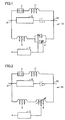
- a current-limiting and power-flow control device 10 of the present invention includes a series capacitor 1, a superconducting current-limiting element 8, reactors 2, 11, a bypass switch 3, a thyristor switch 4, and a control circuit 5.
- Superconducting current-limiting element 8 is connected with capacitor 1.
- a parallel circuit including thyristor switch 4 and reactor 2 is formed so that the parallel circuit is connected in parallel with a series circuit made up of series capacitor 1 and superconducting current-limiting element 8. This parallel circuit is connected, at connection points 21, 22, with the aforementioned series circuit made up of superconducting current-limiting element 8 and series capacitor 1.
- thyristor switch 4 is connected in series with reactor 2.
- control circuit 5 is connected to thyristor switch 4.
- Another parallel circuit including bypass switch 3 and reactor 11 is formed so that this parallel circuit is connected in parallel with the aforementioned series circuit.
- the other parallel circuit is connected, at connection points 21, 22, with the series circuit made up of superconducting current-limiting element 8 and series capacitor 1.
- bypass switch 3 is connected in series with reactor 11. Bypass switch 3 is provided for bypassing superconducting current-limiting element 8 for example when the device is inspected.
- FIG. 2 a second embodiment of the current-limiting and power-flow control device of the present invention will be described.
- current-limiting and power-flow control device 10 basically has a structure similar to that of current-limiting and power-flow control device 10 shown in Fig. 1 , the configuration of the parallel circuit is different from that of current-limiting and power-flow control device 10 shown in Fig. 1 . Namely, in current-limiting and power-flow control device 10 shown in Fig. 2 , thyristor switch 4 is not placed in the parallel circuit. Instead, a reactor 2 and a tapped reactor 9 are connected in series with each other in this parallel circuit. To tapped reactor 9, control circuit 5 is connected. Like current-limiting and power-flow control device 10 shown in Fig.
- current-limiting and power-flow control device 10 having such a structure also enables an overvoltage across the terminals of series capacitor 1 to be suppressed and enables simplification of the configuration of current-limiting and power-flow control device 10 to thereby eliminate restrictions in terms of control due to the arrester or the like.
- current-limiting and power-flow control device 10 shown in Fig. 2 has a larger inductance of the reactors of the parallel circuit that is necessary for the same power flow control as compared with the case where thyristor switch 4 shown in Fig. 1 is used, and therefore achieves a better effect of suppressing fault current relative to that of the device configuration shown in Fig. 1 .
- tapped reactor 9 of the configuration shown in Fig. 2 the rate of change of the inductance (L) is slower as compared with thyristor switch 4 shown in Fig. 1 .
- current-limiting and power-flow control device 10 configured as shown in Fig. 2 may be applied.
- Current-limiting and power-flow control device 10 is current-limiting and power-flow control device 10 in which a superconductor is used and which includes superconducting current-limiting element 8 including the superconductor, a capacitor (series capacitor 1), and a parallel circuit.
- Series capacitor 1 is connected in series with superconducting current-limiting element 8.
- the parallel circuit includes reactor 2 connected in parallel with a series circuit which includes superconducting current-limiting element 8 and series capacitor 1.
- overcurrent short-circuit current
- superconducting current-limiting element 8 causes transition of the superconductor of superconducting current-limiting element 8 to a normal conducting state and thereby causes superconducting current-limiting element 8 to autonomously perform a current-limiting operation.
- an excessively large load excessively large voltage
- the configuration of current-limiting and power-flow control device 10 can be simplified.
- the arrester like that of the conventional device is not used, there is no restriction in terms of control due to the recovery time of the arrester.
- overcurrent causes automatic transition of superconducting current-limiting element 8 to the normal conducting state, a reliable current-limiting operation can be carried out.
- reactor 2 included in the parallel circuit also functions as a current-limiting reactor.
- reactor 2 in this parallel circuit can perform the current-limiting operation.
- the parallel circuit may include a thyristor switch 4 connected in series with reactor 2.
- the autonomous operation of superconducting current-limiting element 8 immediately after occurrence of a fault prevents a load from being applied to series capacitor 1, and thyristor switch 4 can be operated (fully turned on) to surely cause current flowing in superconducting current-limiting element 8 to flow into the parallel circuit. Consequently, the fault current flowing in superconducting current-limiting element 8 can be reduced and superconducting current-limiting element 8 can immediately and surely be caused to recover.
- the parallel circuit may include tapped reactor 9 connected in series with reactor 2.
- the inductance in the parallel circuit is larger than that in the parallel circuit where thyristor switch 4 as described above is used, and therefore, the fault current can be suppressed to a greater extent relative to the case where thyristor switch 4 is used.
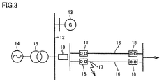
- a model system studied for the simulation is a system in which electric power is transmitted from a power supply 14 through a transformer 15, and it is assumed that a power supply 13 is newly installed on a secondary bus of transformer 15.
- the rated voltage of secondary bus 12 of the transformer was assumed to be 77 kV. It was assumed that three transformers having a rated capacity of 250 MVA were used as transformers 15. It was assumed that transformer 15 had a short-circuit impedance of 22% (based on the self capacity).
- Current-limiting and power-flow control device 10 is installed on a power transmission end of a line extending from bus 12 to a power transmission line 16. Namely, bus 12 and power transmission line 16 including two lines are connected to each other through current-limiting and power-flow control device 10.
- the transmission line had a relatively large capacity among those applied as power transmission lines for 77 kV, and it was assumed that the regular capacity of one line determined by thermal conditions was 170 MW.
- the transmitted power as an index for the sake of the stability should be 80 MW or less (per line). Power transmission of 160 MW is therefore possible even through a single line, as long as 50% of a line reactance X1 (50 km) is compensated for.
- Capacitive reactance Xc of series capacitor 1 of current-limiting and power-flow control device 10 and inductive reactance XL of reactor 2 thereof were studied in the following way.
- the steady-state current flowing in series capacitor 1 and reactor 2 in the case of the parallel LC type, the current flowing in series capacitor 1 and reactor 2 of current-limiting and power-flow control device 10 increases relative to the line current, which causes an increase of the device cost.
- the steady-state current flowing in series capacitor 1 and reactor 2 in the case of power transmission through the two lines was set to twice or less as high as the line current.
- inductive reactance XL of reactor 2 necessary for suppressing short-circuit current was studied.
- the study was conducted of suppression of fault current to 30 kA or less when three-phase short circuit occurs at a fault point 17 in Fig. 3 to thereby cause the current value to become maximum.
- the characteristics of current-limiting and power-flow control device 10 satisfying this condition were determined in the following way.
- Inductive reactance XL of reactor 2 is therefore 0.046 pu or more.
- the current at the start of operation of superconducting current-limiting element 8 in current-limiting and power-flow control device 10 was assumed to be 4800A rms (6.7 kAp). This value is twice as large as the steady-state current (2400A) flowing in the superconducting current-limiting element. Further, the current-limiting resistance in the normal conducting state of superconducting current-limiting element 8 was assumed to be 8 ⁇ .
- Figs. 4 to 6 show the results of a simulation to which current-limiting and power-flow control device 10 of the present invention is applied.
- the horizontal axis of each graph represents time.
- the vertical axis of the graph in Fig. 4 represents the fault current (passing current in the current-limiting and power-flow control device), and the unit of the fault current is kA.
- the vertical axis in Fig. 5 represents the voltage across the terminals of the series capacitor in current-limiting and power-flow control device 10, and the unit of the voltage is kV.
- the vertical axis in Fig. 6 represents the current-limiting resistance, and the unit of the resistance is ⁇ .
- Fig. 4 shows the results of a simulation to which current-limiting and power-flow control device 10 of the present invention is applied.
- the horizontal axis of each graph represents time.
- the vertical axis of the graph in Fig. 4 represents the fault current (passing current in the current-limiting and power-flow control device), and the unit of the fault current
- the magnitude of the voltage across the terminals of series capacitor 1 in current-limiting and power-flow control device 10 at the time of occurrence of a fault is an excessive voltage of approximately 3.2 pu at a half wave immediately after the fault, due to an influence of a slight operation delay of the current limiter for example.
- the voltage is thereafter suppressed to substantially the same extent as the steady-state voltage.
- superconducting current-limiting element 8 which exhibits an autonomous and rapid current-limiting effect is applied to current-limiting and power-flow control device 10 to thereby eliminate the need for installation of an arrester for the sake of protecting series capacitor 1 from an excessive voltage across the terminals, and also eliminate the need for a bypass switch operation for bypassing series capacitor 1 at the time of occurrence of a fault.
- the present invention is particularly advantageously applied to a current-limiting and power-flow control device including a superconducting current-limiting element.
Landscapes
- Engineering & Computer Science (AREA)
- Power Engineering (AREA)
- Emergency Protection Circuit Devices (AREA)
- Containers, Films, And Cooling For Superconductive Devices (AREA)
Abstract
Description
- The present invention relates to a current-limiting and power-flow control device, and more specifically relates to a current-limiting and power-flow control device in which a superconductor is used.
- A parallel LC type power-flow control device installed in an electric power system has been known. In some cases, operation of such a power-flow control device may be accompanied by an increase of the short-circuit capacity of the system having its impedance compensated for by the effect of insertion of a capacitor. In the case where the power-flow control device is applied to such a system having a large short-circuit capacity, it is desirable to equip the device with a current-limiting function for addressing a short-circuit fault in addition to power-flow control, to thereby address the short-circuit current. As one of such devices, a device (current-limiting and power-flow control device) has been proposed in which a current-limiting reactor is connected in series with a thyristor control series capacitor (TCSC) so as to equip the device with the current-limiting function (see for example Yuji Yamazaki et al., "Development of TCSC Application to Fault Current Limiters," IEEJ Transactions on Power and Energy, the Institute of Electrical Engineers of Japan, Vol. 121 (2001), No. 4, pp. 514-519 (NPD 1)).
- NPD 1: Yuji Yamazaki et al., "Development of TCSC Application to Fault Current Limiters," IEEJ Transactions on Power and Energy, the Institute of Electrical Engineers of Japan, Vol. 121 (2001), No. 4, pp. 514-519
- When the aforementioned conventional current-limiting and power-flow control device performs a current-limiting operation, however, a delay occurs before the thyristor switch is fully turned on, because of a time delay in the case where a fault current is detected by a control circuit. It has therefore been necessary to install a protection device such as an arrester in order to protect the capacitor of the TCSC. Installation of such an arrester complicates the device configuration of the current-limiting and power-flow control device, which causes an increase in cost. Further, because it takes a certain time for the arrester to recover, the TCSC has to be bypassed during this time, which may result in a restriction such as restriction on the transmission power of a power transmission line on which the device is installed.
- The present invention has been made to solve the above-described problems, and an object of the present invention is to provide a current-limiting and power-flow control device having no complicated device configuration and having less restrictions in terms of control.
- A current-limiting and power-flow control device according to the present invention is a current-limiting and power-flow control device in which a superconductor is used and which includes a superconducting current-limiting element including the superconductor, a capacitor, and a parallel circuit. The capacitor is connected in series with the superconducting current-limiting element. The parallel circuit includes a reactor connected in parallel with a series circuit including the superconducting current-limiting element and the capacitor.
- Accordingly, overcurrent (short-circuit current) at the time of occurrence of a fault causes transition of the superconductor of the superconducting current-limiting element to a normal conducting state and thereby causes the superconducting current-limiting element to automatically perform a current-limiting operation. Thus, an excessively large load (excessively large voltage) due to the fault can surely be prevented from being applied across the terminals of the capacitor. It is therefore unnecessary, unlike the conventional device, to install an arrester for the sake of capacitor protection, and the configuration of the current-limiting and power-flow control device can be simplified. Further, because the arrester like that of the conventional device is not used, there is no restriction in terms of control due to the recovery time of the arrester. Further, because overcurrent causes automatic transition of the superconducting current-limiting element to the normal conducting state, a reliable current-limiting operation can be carried out.
- In accordance with the present invention, a current-limiting and power-flow control device having no complicated device configuration and having less restrictions in terms of control can be provided.
-
-
Fig. 1 is a circuit diagram for illustrating a first embodiment of the current-limiting and power-flow control device according to the present invention. -
Fig. 2 is a circuit diagram for illustrating a second embodiment of the current-limiting and power-flow control device according to the present invention. -
Fig. 3 is a schematic diagram showing a studied model system. -
Fig. 4 is a graph showing results of a simulation regarding an example of the present invention. -
Fig. 5 is a graph showing results of a simulation regarding an example of the present invention. -
Fig. 6 is a graph showing results of a simulation regarding an example of the present invention. - Embodiments of the present invention will hereinafter be described based on the drawings. In the following drawings, the same or corresponding parts are denoted by the same reference numerals, and a description thereof will not be repeated.
- Referring to
Fig. 1 , a current-limiting and power-flow control device of the present invention will be described. A current-limiting and power-flow control device 10 of the present invention includes a series capacitor 1, a superconducting current-limitingelement 8,reactors bypass switch 3, athyristor switch 4, and acontrol circuit 5. Superconducting current-limiting element 8 is connected with capacitor 1. A parallel circuit includingthyristor switch 4 andreactor 2 is formed so that the parallel circuit is connected in parallel with a series circuit made up of series capacitor 1 and superconducting current-limitingelement 8. This parallel circuit is connected, atconnection points element 8 and series capacitor 1. In the parallel circuit,thyristor switch 4 is connected in series withreactor 2. Tothyristor switch 4,control circuit 5 is connected. Another parallel circuit includingbypass switch 3 andreactor 11 is formed so that this parallel circuit is connected in parallel with the aforementioned series circuit. The other parallel circuit is connected, atconnection points element 8 and series capacitor 1. In the other parallel circuit,bypass switch 3 is connected in series withreactor 11.Bypass switch 3 is provided for bypassing superconducting current-limitingelement 8 for example when the device is inspected. - Next, an operation of current-limiting and power-
flow control device 10 shown inFig. 1 will be described. When a normal operation is done, the superconductor included in superconducting current-limitingelement 8 is kept in a superconducting state. Thus, series capacitor 1,reactor 2, andthyristor switch 4 form a TCSC. For this TCSC, the control angle can be changed to thereby change its impedance characteristic almost continuously from a capacitive one to an inductive one. Thus, the impedance characteristic of the TCSC can be adjusted to thereby control the power flow of an electric power system to which current-limiting and power-flow control device 10 is connected. - In the case where a fault (short-circuit fault for example) occurs in the electric power system to which current-limiting and power-
flow control device 10 is connected, overcurrent due to the fault causes transition of superconducting current-limitingelement 8 to a normal conducting state. As a result, superconducting current-limitingelement 8 automatically performs a current-limiting operation.Thyristor switch 4 can be turned on to cause current flowing in superconducting current-limitingelement 8 to flow in the parallel circuit which includesreactor 2. As a result,reactor 2 functions as a current-limiting reactor and recovery of superconducting current-limitingelement 8 to the superconducting state can be ensured. Further, because it is unnecessary to separately install a protection device (arrester for example) for the sake of protection of series capacitor 1, the configuration of current-limiting and power-flow control device 10 can be simplified and restrictions in terms of control due to the arrester or the like can be eliminated. - Regarding current-limiting and power-
flow control device 10 shown inFig. 1 , in the case where excessively large current flows in current-limiting and power-flow control device 10 due to a fault or the like in the electric power system in which current-limiting and power-flow control device 10 is installed, superconducting current-limitingelement 8 is quenched to immediately and automatically perform a current-limiting operation. Therefore, an overvoltage can surely be prevented from being applied across the terminals of series capacitor 1. After this current-limiting operation, the parallel circuit includingthyristor switch 4 causes current to flow while bypassing superconducting current-limitingelement 8. Thus, the impedance (current-limiting impedance) atreactor 2 limits the overcurrent, and the process thermal energy generated at superconducting current-limitingelement 8 can be reduced. As a result, quick recovery of superconducting current-limitingelement 8 can be made. - Referring to
Fig. 2 , a second embodiment of the current-limiting and power-flow control device of the present invention will be described. - Referring to
Fig. 2 , while current-limiting and power-flow control device 10 basically has a structure similar to that of current-limiting and power-flow control device 10 shown inFig. 1 , the configuration of the parallel circuit is different from that of current-limiting and power-flow control device 10 shown inFig. 1 . Namely, in current-limiting and power-flow control device 10 shown inFig. 2 ,thyristor switch 4 is not placed in the parallel circuit. Instead, areactor 2 and a tappedreactor 9 are connected in series with each other in this parallel circuit. To tappedreactor 9,control circuit 5 is connected. Like current-limiting and power-flow control device 10 shown inFig. 1 , current-limiting and power-flow control device 10 having such a structure also enables an overvoltage across the terminals of series capacitor 1 to be suppressed and enables simplification of the configuration of current-limiting and power-flow control device 10 to thereby eliminate restrictions in terms of control due to the arrester or the like. - It should be noted that current-limiting and power-
flow control device 10 shown inFig. 2 has a larger inductance of the reactors of the parallel circuit that is necessary for the same power flow control as compared with the case wherethyristor switch 4 shown inFig. 1 is used, and therefore achieves a better effect of suppressing fault current relative to that of the device configuration shown inFig. 1 . Regarding tappedreactor 9 of the configuration shown inFig. 2 , the rate of change of the inductance (L) is slower as compared withthyristor switch 4 shown inFig. 1 . Therefore, in the case where there is no problem with the maintenance and/or the stability of the voltage particularly when power is transmitted through one transmission line after removal of a fault and where a decrease of the degree of compensation of the transmission line reactance during a tap operation time of tappedreactor 9 is allowed to a certain extent, current-limiting and power-flow control device 10 configured as shown inFig. 2 may be applied. - The following are characteristic features of the present invention given one by one. A part of them, however, may overlap those of the above-described embodiments.
- Current-limiting and power-
flow control device 10 according to the present invention is current-limiting and power-flow control device 10 in which a superconductor is used and which includes superconducting current-limitingelement 8 including the superconductor, a capacitor (series capacitor 1), and a parallel circuit. Series capacitor 1 is connected in series with superconducting current-limitingelement 8. The parallel circuit includesreactor 2 connected in parallel with a series circuit which includes superconducting current-limitingelement 8 and series capacitor 1. - Accordingly, overcurrent (short-circuit current) at the time of occurrence of a fault causes transition of the superconductor of superconducting current-limiting
element 8 to a normal conducting state and thereby causes superconducting current-limitingelement 8 to autonomously perform a current-limiting operation. Thus, an excessively large load (excessively large voltage) due to the fault can surely be prevented from being applied across the terminals of series capacitor 1. It is therefore unnecessary, unlike the conventional device, to install an arrester for the sake of protection of series capacitor 1, and the configuration of current-limiting and power-flow control device 10 can be simplified. Further, because the arrester like that of the conventional device is not used, there is no restriction in terms of control due to the recovery time of the arrester. Further, because overcurrent causes automatic transition of superconducting current-limitingelement 8 to the normal conducting state, a reliable current-limiting operation can be carried out. - In current-limiting and power-
flow control device 10,reactor 2 included in the parallel circuit also functions as a current-limiting reactor. In this case, when overcurrent at the time of occurrence of a fault causes superconducting current-limitingelement 8 to perform a current-limiting operation and accordingly current flows into the parallel circuit which is connected in parallel with the series circuit including superconducting current-limitingelement 8 and series capacitor 1,reactor 2 in this parallel circuit can perform the current-limiting operation. - In current-limiting and power-
flow control device 10, the parallel circuit may include athyristor switch 4 connected in series withreactor 2. In this case, the autonomous operation of superconducting current-limitingelement 8 immediately after occurrence of a fault prevents a load from being applied to series capacitor 1, andthyristor switch 4 can be operated (fully turned on) to surely cause current flowing in superconducting current-limitingelement 8 to flow into the parallel circuit. Consequently, the fault current flowing in superconducting current-limitingelement 8 can be reduced and superconducting current-limitingelement 8 can immediately and surely be caused to recover. - In current-limiting and power-
flow control device 10, the parallel circuit may include tappedreactor 9 connected in series withreactor 2. In this case, the inductance in the parallel circuit is larger than that in the parallel circuit wherethyristor switch 4 as described above is used, and therefore, the fault current can be suppressed to a greater extent relative to the case wherethyristor switch 4 is used. - A simulation was performed in order to confirm the effects of the present invention.
- Referring to
Fig. 3 , a model system studied for the simulation is a system in which electric power is transmitted from apower supply 14 through atransformer 15, and it is assumed that apower supply 13 is newly installed on a secondary bus oftransformer 15. The rated voltage ofsecondary bus 12 of the transformer was assumed to be 77 kV. It was assumed that three transformers having a rated capacity of 250 MVA were used astransformers 15. It was assumed thattransformer 15 had a short-circuit impedance of 22% (based on the self capacity). - As for the condition for newly installed
power supply 13, it was assumed that the power supply had a capacity of 300 MVA. It was also assumed that newly installedpower supply 13 had a transient reactance Xd' of 20% (based on the self capacity). - Current-limiting and power-
flow control device 10 is installed on a power transmission end of a line extending frombus 12 to apower transmission line 16. Namely,bus 12 andpower transmission line 16 including two lines are connected to each other through current-limiting and power-flow control device 10. - At the opposite ends of
power transmission line 16,breakers 18 are installed respectively. It was assumed that the reactance of eachpower transmission line 16 was an impedance L= 1 mH/km, and the R component and the C component were ignored. It was further assumed that eachtransmission line 16 had a length of 50 km and an applied frequency of 60 Hz. - It was assumed that the model system shown in
Fig. 3 had short-circuit current exceeding a rated breaking current of 31.5 kA of the breaker unless current-limiting and power-flow control device 10 was installed, as described later herein. Supposing that the backward impedance of the system determined from the short-circuit impedance oftransformer 15 is 29.33%@ 1000 MVA and the transient reactance of newly installedpower supply 13 is 66.7%@1000 MVA, the combined impedance of newly installedpower supply 13 and the backward system is 20.4%@1000 MVA. In this system, short-circuit current Is when three-phase short circuit occurs near the end ofbus 12 is 36.8 kA. - As the model system, a radial system was used which was relatively easy to study for verification of the current-limiting operation.
- It was also assumed that the configuration of current-limiting and power-
flow control device 10 was similar to that of current-limiting and power-flow control device 10 shown inFig. 1 . Regarding the following simulation, for the sake of easy verification of the current-limiting operation, the simulation was done under the condition that the two lines were compensated for together by current-limiting and power-flow control device 10 as shown inFig. 3 . - As to the power transmission capacity of
power transmission line 16, it was assumed that the transmission line had a relatively large capacity among those applied as power transmission lines for 77 kV, and it was assumed that the regular capacity of one line determined by thermal conditions was 170 MW. - Regarding this simulation, it was assumed that the load cannot be changed in the radial system. In this case, if one of the lines fails, all current flows in the sound line. The maximum power transmission capacity of the two lines is therefore 170 MW.
- Meanwhile, if it is assumed that the phase difference angle is 15° in terms of the stability of the power transmission line, the transmitted power as an index for the sake of the stability should be 80 MW or less (per line). Power transmission of 160 MW is therefore possible even through a single line, as long as 50% of a line reactance X1 (50 km) is compensated for.
- Based on the above-described study, it was assumed that the system used for the simulation had the conditions that the power transmission capacity was increased by 50% compensation (corresponding to 25 km) of X1 (50 km) of
power transmission line 16 and that the power transmitted by the two 77 kV power transmission lines was 160 MW. - Capacitive reactance Xc of series capacitor 1 of current-limiting and power-
flow control device 10 and inductive reactance XL ofreactor 2 thereof were studied in the following way. - It was assumed first that the reactance in a steady state was 50% compensation of the line reactance. In the two-line state, the line reactance is: line reactance X1 = co x 1 mH x 50 km / two lines = 9.42 Ω, and the reactance based on 77 kV and 1000 MVA is: X1= 1.59 pu. Thus, in the case of 50% compensation, reactance XFCL of current-limiting and power-
flow control device 10 is -j0.8 pu. Further, in the case of power transmission through one line after removal of a fault, the reactance is XFCL = -j1.6pu so that 50% compensation of transmission line reactance X (=3.18 pu) of a single line is provided. - As to the steady-state current flowing in series capacitor 1 and
reactor 2, in the case of the parallel LC type, the current flowing in series capacitor 1 andreactor 2 of current-limiting and power-flow control device 10 increases relative to the line current, which causes an increase of the device cost. In view of this, the steady-state current flowing in series capacitor 1 andreactor 2 in the case of power transmission through the two lines was set to twice or less as high as the line current. - Accordingly, for power transmission through the two lines, capacitive reactance Xc = -j0.4 pu and inductive reactance XL = j0.8 pu were used, and it was adjusted to XL= j0.53 pu in the case of power transmission through one line.
- It was assumed that these conditions could be achieved for current-limiting and power-
flow control device 10 shown inFig. 1 by a fixed reactance (X) of j0.2 pu and through use in a range of 30° ≤ firing angle β ≤ 40°, where β was an angle from a voltage peak. In this case, XL at the time whenthyristor switch 4 is fully turned on is the fixed reactance (X) of j0.2 pu. - Next, inductive reactance XL of
reactor 2 necessary for suppressing short-circuit current was studied. Regarding a model system as described above, the study was conducted of suppression of fault current to 30 kA or less when three-phase short circuit occurs at afault point 17 inFig. 3 to thereby cause the current value to become maximum. The characteristics of current-limiting and power-flow control device 10 satisfying this condition were determined in the following way. Specifically, from an inductive reactance (XL) ofreactor 2 functioning as a current-limiting reactor of current-limiting and power-flow control device 10 of an example and the aforementioned combined impedance ofpower supply 13 and the backward system of 20.4%@1000 MVA, fault current is: Is = 1/ (XL + 0.204) x 1000000 kVA / (√3 x 77 kV) ≤ 30 kA under the condition that XL is XL ≥ 0.046 pu. Inductive reactance XL ofreactor 2 is therefore 0.046 pu or more. - Inductive reactance XL = fixed reactance X = j0.2 pu when
thyristor switch 4 is fully turned on satisfies a condition of 0.046 pu or more. Namely, it is seen that the current-limiting effect whenthyristor switch 4 is fully turned on is satisfactory. - Further, as a model for analyzing superconducting current-limiting
element 8 in current-limiting and power-flow control device 10 shown inFig. 1, 4 .3.1 (an EMTP analysis simple model of an SN dislocation type superconducting current limiter) in Technical Report of the Institute of Electrical Engineers of Japan, No. 1088 was used. The current-limiting resistance after removal of a fault was set so that it linearly decreased from the removal of the fault to 200 ms. Then, with reference to the resistance occurrence waveform (a change with time of the generated resistance value) due to a superconducting coil for 6.6 kV 1.5 kA class quench-type current limiter, the operation time Top of superconducting current-limitingelement 8 was assumed to be 1 ms. - Further, the current at the start of operation of superconducting current-limiting
element 8 in current-limiting and power-flow control device 10 was assumed to be 4800A rms (6.7 kAp). This value is twice as large as the steady-state current (2400A) flowing in the superconducting current-limiting element. Further, the current-limiting resistance in the normal conducting state of superconducting current-limitingelement 8 was assumed to be 8 Ω. - As for an assumed type of the fault, it was assumed that three-phase short-circuit (3LS) occurred at the
fault point 17 shown inFig. 3 (near the power-supply-side end of the bus 3LS). As for a fault sequence, it was assumed that the three-phase short circuit occurred at time T = 0.3 sec,breaker 18 operates at time T = 0.4 sec (both ends of the CB were opened), and the fault line was broken. It was further assumed that at time T = 0.6 sec, the current limiter (superconducting current-limiting element 8) recovered to the steady state. -
Figs. 4 to 6 show the results of a simulation to which current-limiting and power-flow control device 10 of the present invention is applied. InFigs. 4 to 6 , the horizontal axis of each graph represents time. The vertical axis of the graph inFig. 4 represents the fault current (passing current in the current-limiting and power-flow control device), and the unit of the fault current is kA. The vertical axis inFig. 5 represents the voltage across the terminals of the series capacitor in current-limiting and power-flow control device 10, and the unit of the voltage is kV. The vertical axis inFig. 6 represents the current-limiting resistance, and the unit of the resistance is Ω. In the example of the present invention, as seen fromFig. 4 , the AC component of the short-circuit current from which the DC component is removed is suppressed to 30kA rms (= 42.4 kAp) or less and thus appropriate current limiting is achieved. InFigs. 4 to 6 , respective components of the three phases of the passing current in the current-limiting and power-flow control device are indicated as graph A, graph B, and graph C, respectively. - Further, as seen from
Fig. 5 , the magnitude of the voltage across the terminals of series capacitor 1 in current-limiting and power-flow control device 10 at the time of occurrence of a fault is an excessive voltage of approximately 3.2 pu at a half wave immediately after the fault, due to an influence of a slight operation delay of the current limiter for example. The voltage, however, is thereafter suppressed to substantially the same extent as the steady-state voltage. - Thus, superconducting current-limiting
element 8 which exhibits an autonomous and rapid current-limiting effect is applied to current-limiting and power-flow control device 10 to thereby eliminate the need for installation of an arrester for the sake of protecting series capacitor 1 from an excessive voltage across the terminals, and also eliminate the need for a bypass switch operation for bypassing series capacitor 1 at the time of occurrence of a fault. - Regarding the above-described simulation, the case where current-limiting and power-
flow control device 10 having the configuration shown inFig. 1 was used was studied. Similar effects, however, can also be obtained from use of the current-limiting and power-flow control device 10 having tappedreactor 9 as shown inFig. 2 . Specifically, it was assumed that capacitive reactance Xc of series capacitor 1, inductive reactance XL1 ofreactor 2, and inductive reactance XL2 of tappedreactor 9 in current-limiting and power-flow control device 10 shown inFig. 2 were: capacitive reactance Xc = -j0.4 pu, inductive reactance XL1 = j0.53 pu, and inductive reactance XL2 = 0 to j0.27 pu. It should be noted that the inductive reactance in the steady state with the two lines was assumed to be XL2 = j0.27 pu. At this time as well, XL = -j0.8 pu and thus the condition of 0.046 pu or more is satisfied. Even a simulation using such conditions provided similar effects to the case where current-limiting and power-flow control device 10 having the structure shown inFig. 1 is used. - It should be understood that the embodiments and examples disclosed herein are given by way of illustration in all respects, not by way of limitation. It is intended that the scope of the present invention is defined by claims, not by the description above, and encompasses all modifications and variations equivalent in meaning and scope to the claims.
- The present invention is particularly advantageously applied to a current-limiting and power-flow control device including a superconducting current-limiting element.
- 1 series capacitor; 2, 11 reactor; 3 bypass switch; 4 thyristor switch; 5 control circuit; 6 current-limiting reactor; 8 superconducting current-limiting element; 9 tapped reactor; 10, 100 current-limiting and power-flow control device; 12 substation bus; 16 power transmission line; 13 newly installed power supply; 14 power supply; 15 transformer; 17 fault point; 18 breaker; 21, 22 connection point
Claims (4)
- A current-limiting and power-flow control device in which a superconductor is used, comprising:a superconducting current-limiting element including said superconductor;a capacitor connected in series with said superconducting current-limiting element; anda parallel circuit including a reactor connected in parallel with a series circuit including said superconducting current-limiting element and said capacitor.
- The current-limiting and power-flow control device according to claim 1, wherein said reactor included in said parallel circuit functions as a current-limiting reactor.
- The current-limiting and power-flow control device according to claim 1 or 2, wherein said parallel circuit includes a thyristor switch connected in series with said reactor.
- The current-limiting and power-flow control device according to claim 1 or 2, wherein said parallel circuit includes a tapped reactor connected in series with said reactor.
Applications Claiming Priority (2)
| Application Number | Priority Date | Filing Date | Title |
|---|---|---|---|
| JP2013075938A JP2014204460A (en) | 2013-04-01 | 2013-04-01 | Current-limiting/current flow controller |
| PCT/JP2014/058535 WO2014162949A1 (en) | 2013-04-01 | 2014-03-26 | Current-limiting/flow control device |
Publications (3)
| Publication Number | Publication Date |
|---|---|
| EP2983263A1 true EP2983263A1 (en) | 2016-02-10 |
| EP2983263A4 EP2983263A4 (en) | 2017-01-11 |
| EP2983263B1 EP2983263B1 (en) | 2019-11-06 |
Family
ID=51658247
Family Applications (1)
| Application Number | Title | Priority Date | Filing Date |
|---|---|---|---|
| EP14779757.5A Active EP2983263B1 (en) | 2013-04-01 | 2014-03-26 | Current-limiting/flow control device |
Country Status (7)
| Country | Link |
|---|---|
| US (1) | US9762051B2 (en) |
| EP (1) | EP2983263B1 (en) |
| JP (1) | JP2014204460A (en) |
| KR (1) | KR20150136534A (en) |
| CN (1) | CN105103397B (en) |
| ES (1) | ES2759913T3 (en) |
| WO (1) | WO2014162949A1 (en) |
Families Citing this family (6)
| Publication number | Priority date | Publication date | Assignee | Title |
|---|---|---|---|---|
| JP6069073B2 (en) * | 2013-04-01 | 2017-01-25 | 住友電気工業株式会社 | Current limiting device |
| KR101622187B1 (en) * | 2014-05-13 | 2016-05-18 | 엘에스산전 주식회사 | Fault current limiter |
| KR102077528B1 (en) * | 2019-07-11 | 2020-02-14 | 아이에프텍(주) | Structure of generator and uninterruptible power system based on internet of things and control method thereof |
| CN111541231A (en) * | 2020-05-19 | 2020-08-14 | 中天集团上海超导技术有限公司 | Method for enhancing fault current resistance of three-phase coaxial superconducting cable |
| CN112165078B (en) * | 2020-06-15 | 2022-07-05 | 国网湖北省电力有限公司黄冈供电公司 | Resonant current limiter input control method utilizing short-circuit current change rate |
| CN121529460B (en) * | 2026-01-15 | 2026-04-10 | 杭州布雷科电气有限公司 | Discrete combinatorial optimization control method based on switchable series-parallel current limiting circuits using IGBTs and contactors |
Family Cites Families (22)
| Publication number | Priority date | Publication date | Assignee | Title |
|---|---|---|---|---|
| DE1932379C3 (en) * | 1969-06-26 | 1978-05-11 | Siemens Ag, 1000 Berlin Und 8000 Muenchen | Coil with variable inductance as a current limiting device for energy transmission systems |
| JP2901068B2 (en) | 1988-10-07 | 1999-06-02 | 株式会社東芝 | Current limiting device |
| JPH02116184A (en) * | 1988-10-26 | 1990-04-27 | Toshiba Corp | Pulse laser power source device |
| JP2941833B2 (en) | 1989-01-27 | 1999-08-30 | 株式会社東芝 | Superconducting current limiting device |
| JPH03245725A (en) | 1990-02-22 | 1991-11-01 | Takaoka Electric Mfg Co Ltd | Overcurrent limiter |
| JP2947927B2 (en) * | 1990-11-30 | 1999-09-13 | 東京電力株式会社 | Superconducting current limiting device |
| JPH07209371A (en) * | 1994-01-21 | 1995-08-11 | Fuji Electric Co Ltd | Cable AC withstanding voltage test apparatus and method |
| JPH0974682A (en) * | 1995-09-04 | 1997-03-18 | Hitachi Ltd | Series capacitor controller |
| JP2850810B2 (en) * | 1995-11-01 | 1999-01-27 | 日新電機株式会社 | Superconducting current limiting device |
| JPH11146555A (en) * | 1997-11-05 | 1999-05-28 | Toshiba Corp | Superconducting current limiting device |
| JP2000090788A (en) | 1998-09-09 | 2000-03-31 | Toshiba Corp | Current-limiting device and current-limiting device |
| JP2001078362A (en) * | 1999-09-07 | 2001-03-23 | Toshiba Corp | Power system stabilizer |
| DE19963181C2 (en) | 1999-12-27 | 2002-04-18 | Siemens Ag | Resistive current limiter device for direct or alternating current with at least one conductor track with high-T¶c¶ superconductor material |
| JP2004350337A (en) * | 2003-05-20 | 2004-12-09 | National Institute Of Advanced Industrial & Technology | Power flow control device with current limiting function |
| JP4851814B2 (en) * | 2006-03-01 | 2012-01-11 | 株式会社東芝 | Power system |
| KR100780706B1 (en) * | 2006-08-17 | 2007-11-30 | 엘에스산전 주식회사 | Hybrid Superconducting fault current limiter |
| US20080056327A1 (en) * | 2006-08-30 | 2008-03-06 | Hatch Ltd. | Method and system for predictive electrode lowering in a furnace |
| KR100888147B1 (en) | 2007-08-20 | 2009-03-13 | 한국전력공사 | Hybrid superconducting fault current limiter |
| CN101183129A (en) | 2007-11-26 | 2008-05-21 | 天津理工大学 | Fault detection system and detection method of a quench type superconducting fault current limiter |
| JP5187750B2 (en) * | 2008-07-04 | 2013-04-24 | 株式会社前川製作所 | Magnetic saturation type fault current limiter |
| CN102035196A (en) * | 2010-12-30 | 2011-04-27 | 东南大学 | Thyristor controlled series compensator-based fault current limiting device |
| CN102646968B (en) * | 2012-05-04 | 2015-03-18 | 中国科学院电工研究所 | Reactor type short-circuit fault current limiter |
-
2013
- 2013-04-01 JP JP2013075938A patent/JP2014204460A/en active Pending
-
2014
- 2014-03-26 ES ES14779757T patent/ES2759913T3/en active Active
- 2014-03-26 WO PCT/JP2014/058535 patent/WO2014162949A1/en not_active Ceased
- 2014-03-26 US US14/770,998 patent/US9762051B2/en not_active Expired - Fee Related
- 2014-03-26 CN CN201480019156.2A patent/CN105103397B/en not_active Expired - Fee Related
- 2014-03-26 EP EP14779757.5A patent/EP2983263B1/en active Active
- 2014-03-26 KR KR1020157031202A patent/KR20150136534A/en not_active Ceased
Also Published As
| Publication number | Publication date |
|---|---|
| CN105103397B (en) | 2019-01-11 |
| WO2014162949A1 (en) | 2014-10-09 |
| JP2014204460A (en) | 2014-10-27 |
| KR20150136534A (en) | 2015-12-07 |
| CN105103397A (en) | 2015-11-25 |
| US9762051B2 (en) | 2017-09-12 |
| US20160020604A1 (en) | 2016-01-21 |
| EP2983263A4 (en) | 2017-01-11 |
| EP2983263B1 (en) | 2019-11-06 |
| ES2759913T3 (en) | 2020-05-12 |
Similar Documents
| Publication | Publication Date | Title |
|---|---|---|
| EP2983263B1 (en) | Current-limiting/flow control device | |
| WO2019119886A1 (en) | Series compensator, and control method | |
| Liu et al. | Protection of single-phase fault at the transformer valve side of FB-MMC-based bipolar HVdc systems | |
| Wang et al. | Control and protection strategy for MMC MTDC system under converter-side AC fault during converter blocking failure | |
| US7605499B2 (en) | Systems and methods of dynamic reactive support for a power transmission system | |
| KR101673956B1 (en) | Superconducting fault current limiter for protrcting power system and circuit breaker system including the same | |
| US10218170B2 (en) | Current-limiting device utilizing a superconductor for a current-limiting operation | |
| Župan et al. | Transients caused by switching of 420 kV three-phase variable shunt reactor | |
| Jakka et al. | Protection design considerations of a 10 kV SiC MOSFET enabled mobile utilities support equipment based solid state transformer (muse-SST) | |
| CN101646985A (en) | Method and apparatus for mitigation of dynamic overvoltage | |
| Salcedo et al. | Long duration overvoltages due to current backfeeding in secondary networks | |
| Mohanty et al. | Current restrained undervoltage protection scheme of converter dominated microgrids | |
| Panasetsky et al. | On the problem of shunt reactor tripping during single-and three-phase auto-reclosing | |
| Ben-Ashour et al. | Transient overvoltages protection for series capacitors in compensated transmission lines | |
| Golshani et al. | Facts based fault current limiter utilization in HV grid | |
| Boribun et al. | Comparative study on a fault current limiter with thyristor-controlled impedances | |
| Zeng et al. | Investigation on Internal Overvoltage Performance of EHV Multi-Break Circuit Breaker | |
| Jannati et al. | A novel approach for optimizing dead time of extra high voltage transmission lines | |
| Patcharoen et al. | Inrush current analysis for switching large shunt capacitor bank in a 230 kV substation system | |
| An et al. | HVDC Scheme’s Dynamic/Transient Responses to AC and DC Faults | |
| Klucznik et al. | Resonance problems in UHV transmission lines | |
| Bahrami | An integrated control scheme for dynamic voltage restorer to limit downstream fault currents | |
| Neamt et al. | Some Considerations About Overvoltages During and After The Disconnection of a Photovoltaic Park | |
| Štumberger et al. | Medium-voltage distribution feeders in closed-loop arrangement–neutral point grounding | |
| Cuello-Reyna et al. | Transient Performance for a Series-Compensation in a High Voltage Transmission System |
Legal Events
| Date | Code | Title | Description |
|---|---|---|---|
| PUAI | Public reference made under article 153(3) epc to a published international application that has entered the european phase |
Free format text: ORIGINAL CODE: 0009012 |
|
| 17P | Request for examination filed |
Effective date: 20151021 |
|
| AK | Designated contracting states |
Kind code of ref document: A1 Designated state(s): AL AT BE BG CH CY CZ DE DK EE ES FI FR GB GR HR HU IE IS IT LI LT LU LV MC MK MT NL NO PL PT RO RS SE SI SK SM TR |
|
| AX | Request for extension of the european patent |
Extension state: BA ME |
|
| DAX | Request for extension of the european patent (deleted) | ||
| A4 | Supplementary search report drawn up and despatched |
Effective date: 20161209 |
|
| RIC1 | Information provided on ipc code assigned before grant |
Ipc: H02H 9/02 20060101AFI20161205BHEP Ipc: H02H 3/08 20060101ALI20161205BHEP |
|
| STAA | Information on the status of an ep patent application or granted ep patent |
Free format text: STATUS: EXAMINATION IS IN PROGRESS |
|
| 17Q | First examination report despatched |
Effective date: 20181019 |
|
| GRAP | Despatch of communication of intention to grant a patent |
Free format text: ORIGINAL CODE: EPIDOSNIGR1 |
|
| STAA | Information on the status of an ep patent application or granted ep patent |
Free format text: STATUS: GRANT OF PATENT IS INTENDED |
|
| INTG | Intention to grant announced |
Effective date: 20190606 |
|
| GRAS | Grant fee paid |
Free format text: ORIGINAL CODE: EPIDOSNIGR3 |
|
| GRAA | (expected) grant |
Free format text: ORIGINAL CODE: 0009210 |
|
| STAA | Information on the status of an ep patent application or granted ep patent |
Free format text: STATUS: THE PATENT HAS BEEN GRANTED |
|
| AK | Designated contracting states |
Kind code of ref document: B1 Designated state(s): AL AT BE BG CH CY CZ DE DK EE ES FI FR GB GR HR HU IE IS IT LI LT LU LV MC MK MT NL NO PL PT RO RS SE SI SK SM TR |
|
| REG | Reference to a national code |
Ref country code: GB Ref legal event code: FG4D |
|
| REG | Reference to a national code |
Ref country code: CH Ref legal event code: EP Ref country code: AT Ref legal event code: REF Ref document number: 1200094 Country of ref document: AT Kind code of ref document: T Effective date: 20191115 |
|
| REG | Reference to a national code |
Ref country code: DE Ref legal event code: R096 Ref document number: 602014056354 Country of ref document: DE |
|
| REG | Reference to a national code |
Ref country code: IE Ref legal event code: FG4D |
|
| REG | Reference to a national code |
Ref country code: NL Ref legal event code: MP Effective date: 20191106 |
|
| REG | Reference to a national code |
Ref country code: LT Ref legal event code: MG4D |
|
| PG25 | Lapsed in a contracting state [announced via postgrant information from national office to epo] |
Ref country code: PT Free format text: LAPSE BECAUSE OF FAILURE TO SUBMIT A TRANSLATION OF THE DESCRIPTION OR TO PAY THE FEE WITHIN THE PRESCRIBED TIME-LIMIT Effective date: 20200306 Ref country code: FI Free format text: LAPSE BECAUSE OF FAILURE TO SUBMIT A TRANSLATION OF THE DESCRIPTION OR TO PAY THE FEE WITHIN THE PRESCRIBED TIME-LIMIT Effective date: 20191106 Ref country code: LV Free format text: LAPSE BECAUSE OF FAILURE TO SUBMIT A TRANSLATION OF THE DESCRIPTION OR TO PAY THE FEE WITHIN THE PRESCRIBED TIME-LIMIT Effective date: 20191106 Ref country code: SE Free format text: LAPSE BECAUSE OF FAILURE TO SUBMIT A TRANSLATION OF THE DESCRIPTION OR TO PAY THE FEE WITHIN THE PRESCRIBED TIME-LIMIT Effective date: 20191106 Ref country code: BG Free format text: LAPSE BECAUSE OF FAILURE TO SUBMIT A TRANSLATION OF THE DESCRIPTION OR TO PAY THE FEE WITHIN THE PRESCRIBED TIME-LIMIT Effective date: 20200206 Ref country code: PL Free format text: LAPSE BECAUSE OF FAILURE TO SUBMIT A TRANSLATION OF THE DESCRIPTION OR TO PAY THE FEE WITHIN THE PRESCRIBED TIME-LIMIT Effective date: 20191106 Ref country code: LT Free format text: LAPSE BECAUSE OF FAILURE TO SUBMIT A TRANSLATION OF THE DESCRIPTION OR TO PAY THE FEE WITHIN THE PRESCRIBED TIME-LIMIT Effective date: 20191106 Ref country code: NO Free format text: LAPSE BECAUSE OF FAILURE TO SUBMIT A TRANSLATION OF THE DESCRIPTION OR TO PAY THE FEE WITHIN THE PRESCRIBED TIME-LIMIT Effective date: 20200206 Ref country code: GR Free format text: LAPSE BECAUSE OF FAILURE TO SUBMIT A TRANSLATION OF THE DESCRIPTION OR TO PAY THE FEE WITHIN THE PRESCRIBED TIME-LIMIT Effective date: 20200207 Ref country code: NL Free format text: LAPSE BECAUSE OF FAILURE TO SUBMIT A TRANSLATION OF THE DESCRIPTION OR TO PAY THE FEE WITHIN THE PRESCRIBED TIME-LIMIT Effective date: 20191106 |
|
| PGFP | Annual fee paid to national office [announced via postgrant information from national office to epo] |
Ref country code: IT Payment date: 20200221 Year of fee payment: 7 Ref country code: DE Payment date: 20200310 Year of fee payment: 7 Ref country code: GB Payment date: 20200318 Year of fee payment: 7 |
|
| REG | Reference to a national code |
Ref country code: ES Ref legal event code: FG2A Ref document number: 2759913 Country of ref document: ES Kind code of ref document: T3 Effective date: 20200512 |
|
| PG25 | Lapsed in a contracting state [announced via postgrant information from national office to epo] |
Ref country code: HR Free format text: LAPSE BECAUSE OF FAILURE TO SUBMIT A TRANSLATION OF THE DESCRIPTION OR TO PAY THE FEE WITHIN THE PRESCRIBED TIME-LIMIT Effective date: 20191106 Ref country code: IS Free format text: LAPSE BECAUSE OF FAILURE TO SUBMIT A TRANSLATION OF THE DESCRIPTION OR TO PAY THE FEE WITHIN THE PRESCRIBED TIME-LIMIT Effective date: 20200306 Ref country code: RS Free format text: LAPSE BECAUSE OF FAILURE TO SUBMIT A TRANSLATION OF THE DESCRIPTION OR TO PAY THE FEE WITHIN THE PRESCRIBED TIME-LIMIT Effective date: 20191106 |
|
| PG25 | Lapsed in a contracting state [announced via postgrant information from national office to epo] |
Ref country code: AL Free format text: LAPSE BECAUSE OF FAILURE TO SUBMIT A TRANSLATION OF THE DESCRIPTION OR TO PAY THE FEE WITHIN THE PRESCRIBED TIME-LIMIT Effective date: 20191106 |
|
| PG25 | Lapsed in a contracting state [announced via postgrant information from national office to epo] |
Ref country code: EE Free format text: LAPSE BECAUSE OF FAILURE TO SUBMIT A TRANSLATION OF THE DESCRIPTION OR TO PAY THE FEE WITHIN THE PRESCRIBED TIME-LIMIT Effective date: 20191106 Ref country code: DK Free format text: LAPSE BECAUSE OF FAILURE TO SUBMIT A TRANSLATION OF THE DESCRIPTION OR TO PAY THE FEE WITHIN THE PRESCRIBED TIME-LIMIT Effective date: 20191106 Ref country code: RO Free format text: LAPSE BECAUSE OF FAILURE TO SUBMIT A TRANSLATION OF THE DESCRIPTION OR TO PAY THE FEE WITHIN THE PRESCRIBED TIME-LIMIT Effective date: 20191106 Ref country code: CZ Free format text: LAPSE BECAUSE OF FAILURE TO SUBMIT A TRANSLATION OF THE DESCRIPTION OR TO PAY THE FEE WITHIN THE PRESCRIBED TIME-LIMIT Effective date: 20191106 |
|
| PGFP | Annual fee paid to national office [announced via postgrant information from national office to epo] |
Ref country code: ES Payment date: 20200401 Year of fee payment: 7 |
|
| REG | Reference to a national code |
Ref country code: DE Ref legal event code: R097 Ref document number: 602014056354 Country of ref document: DE |
|
| REG | Reference to a national code |
Ref country code: AT Ref legal event code: MK05 Ref document number: 1200094 Country of ref document: AT Kind code of ref document: T Effective date: 20191106 |
|
| PG25 | Lapsed in a contracting state [announced via postgrant information from national office to epo] |
Ref country code: SM Free format text: LAPSE BECAUSE OF FAILURE TO SUBMIT A TRANSLATION OF THE DESCRIPTION OR TO PAY THE FEE WITHIN THE PRESCRIBED TIME-LIMIT Effective date: 20191106 Ref country code: SK Free format text: LAPSE BECAUSE OF FAILURE TO SUBMIT A TRANSLATION OF THE DESCRIPTION OR TO PAY THE FEE WITHIN THE PRESCRIBED TIME-LIMIT Effective date: 20191106 |
|
| PLBE | No opposition filed within time limit |
Free format text: ORIGINAL CODE: 0009261 |
|
| STAA | Information on the status of an ep patent application or granted ep patent |
Free format text: STATUS: NO OPPOSITION FILED WITHIN TIME LIMIT |
|
| 26N | No opposition filed |
Effective date: 20200807 |
|
| PG25 | Lapsed in a contracting state [announced via postgrant information from national office to epo] |
Ref country code: MC Free format text: LAPSE BECAUSE OF FAILURE TO SUBMIT A TRANSLATION OF THE DESCRIPTION OR TO PAY THE FEE WITHIN THE PRESCRIBED TIME-LIMIT Effective date: 20191106 |
|
| REG | Reference to a national code |
Ref country code: CH Ref legal event code: PL |
|
| PG25 | Lapsed in a contracting state [announced via postgrant information from national office to epo] |
Ref country code: AT Free format text: LAPSE BECAUSE OF FAILURE TO SUBMIT A TRANSLATION OF THE DESCRIPTION OR TO PAY THE FEE WITHIN THE PRESCRIBED TIME-LIMIT Effective date: 20191106 Ref country code: SI Free format text: LAPSE BECAUSE OF FAILURE TO SUBMIT A TRANSLATION OF THE DESCRIPTION OR TO PAY THE FEE WITHIN THE PRESCRIBED TIME-LIMIT Effective date: 20191106 |
|
| REG | Reference to a national code |
Ref country code: BE Ref legal event code: MM Effective date: 20200331 |
|
| PG25 | Lapsed in a contracting state [announced via postgrant information from national office to epo] |
Ref country code: LU Free format text: LAPSE BECAUSE OF NON-PAYMENT OF DUE FEES Effective date: 20200326 |
|
| PG25 | Lapsed in a contracting state [announced via postgrant information from national office to epo] |
Ref country code: LI Free format text: LAPSE BECAUSE OF NON-PAYMENT OF DUE FEES Effective date: 20200331 Ref country code: FR Free format text: LAPSE BECAUSE OF NON-PAYMENT OF DUE FEES Effective date: 20200331 Ref country code: CH Free format text: LAPSE BECAUSE OF NON-PAYMENT OF DUE FEES Effective date: 20200331 Ref country code: IE Free format text: LAPSE BECAUSE OF NON-PAYMENT OF DUE FEES Effective date: 20200326 |
|
| PG25 | Lapsed in a contracting state [announced via postgrant information from national office to epo] |
Ref country code: BE Free format text: LAPSE BECAUSE OF NON-PAYMENT OF DUE FEES Effective date: 20200331 |
|
| REG | Reference to a national code |
Ref country code: DE Ref legal event code: R119 Ref document number: 602014056354 Country of ref document: DE |
|
| GBPC | Gb: european patent ceased through non-payment of renewal fee |
Effective date: 20210326 |
|
| PG25 | Lapsed in a contracting state [announced via postgrant information from national office to epo] |
Ref country code: GB Free format text: LAPSE BECAUSE OF NON-PAYMENT OF DUE FEES Effective date: 20210326 Ref country code: DE Free format text: LAPSE BECAUSE OF NON-PAYMENT OF DUE FEES Effective date: 20211001 |
|
| PG25 | Lapsed in a contracting state [announced via postgrant information from national office to epo] |
Ref country code: IT Free format text: LAPSE BECAUSE OF NON-PAYMENT OF DUE FEES Effective date: 20210326 |
|
| PG25 | Lapsed in a contracting state [announced via postgrant information from national office to epo] |
Ref country code: TR Free format text: LAPSE BECAUSE OF FAILURE TO SUBMIT A TRANSLATION OF THE DESCRIPTION OR TO PAY THE FEE WITHIN THE PRESCRIBED TIME-LIMIT Effective date: 20191106 Ref country code: MT Free format text: LAPSE BECAUSE OF FAILURE TO SUBMIT A TRANSLATION OF THE DESCRIPTION OR TO PAY THE FEE WITHIN THE PRESCRIBED TIME-LIMIT Effective date: 20191106 Ref country code: CY Free format text: LAPSE BECAUSE OF FAILURE TO SUBMIT A TRANSLATION OF THE DESCRIPTION OR TO PAY THE FEE WITHIN THE PRESCRIBED TIME-LIMIT Effective date: 20191106 |
|
| PG25 | Lapsed in a contracting state [announced via postgrant information from national office to epo] |
Ref country code: MK Free format text: LAPSE BECAUSE OF FAILURE TO SUBMIT A TRANSLATION OF THE DESCRIPTION OR TO PAY THE FEE WITHIN THE PRESCRIBED TIME-LIMIT Effective date: 20191106 |
|
| REG | Reference to a national code |
Ref country code: ES Ref legal event code: FD2A Effective date: 20220630 |
|
| PG25 | Lapsed in a contracting state [announced via postgrant information from national office to epo] |
Ref country code: ES Free format text: LAPSE BECAUSE OF NON-PAYMENT OF DUE FEES Effective date: 20210327 |