EP2983246B1 - Elektrische Verbindungsanordnung - Google Patents
Elektrische Verbindungsanordnung Download PDFInfo
- Publication number
- EP2983246B1 EP2983246B1 EP14179926.2A EP14179926A EP2983246B1 EP 2983246 B1 EP2983246 B1 EP 2983246B1 EP 14179926 A EP14179926 A EP 14179926A EP 2983246 B1 EP2983246 B1 EP 2983246B1
- Authority
- EP
- European Patent Office
- Prior art keywords
- circuit board
- connection
- semiconductor component
- accordance
- contact element
- Prior art date
- Legal status (The legal status is an assumption and is not a legal conclusion. Google has not performed a legal analysis and makes no representation as to the accuracy of the status listed.)
- Active
Links
Images
Classifications
-
- H—ELECTRICITY
- H01—ELECTRIC ELEMENTS
- H01R—ELECTRICALLY-CONDUCTIVE CONNECTIONS; STRUCTURAL ASSOCIATIONS OF A PLURALITY OF MUTUALLY-INSULATED ELECTRICAL CONNECTING ELEMENTS; COUPLING DEVICES; CURRENT COLLECTORS
- H01R12/00—Structural associations of a plurality of mutually-insulated electrical connecting elements, specially adapted for printed circuits, e.g. printed circuit boards [PCB], flat or ribbon cables, or like generally planar structures, e.g. terminal strips, terminal blocks; Coupling devices specially adapted for printed circuits, flat or ribbon cables, or like generally planar structures; Terminals specially adapted for contact with, or insertion into, printed circuits, flat or ribbon cables, or like generally planar structures
- H01R12/70—Coupling devices
- H01R12/7076—Coupling devices for connection between PCB and component, e.g. display
-
- H—ELECTRICITY
- H01—ELECTRIC ELEMENTS
- H01R—ELECTRICALLY-CONDUCTIVE CONNECTIONS; STRUCTURAL ASSOCIATIONS OF A PLURALITY OF MUTUALLY-INSULATED ELECTRICAL CONNECTING ELEMENTS; COUPLING DEVICES; CURRENT COLLECTORS
- H01R12/00—Structural associations of a plurality of mutually-insulated electrical connecting elements, specially adapted for printed circuits, e.g. printed circuit boards [PCB], flat or ribbon cables, or like generally planar structures, e.g. terminal strips, terminal blocks; Coupling devices specially adapted for printed circuits, flat or ribbon cables, or like generally planar structures; Terminals specially adapted for contact with, or insertion into, printed circuits, flat or ribbon cables, or like generally planar structures
- H01R12/70—Coupling devices
- H01R12/71—Coupling devices for rigid printing circuits or like structures
- H01R12/712—Coupling devices for rigid printing circuits or like structures co-operating with the surface of the printed circuit or with a coupling device exclusively provided on the surface of the printed circuit
- H01R12/714—Coupling devices for rigid printing circuits or like structures co-operating with the surface of the printed circuit or with a coupling device exclusively provided on the surface of the printed circuit with contacts abutting directly the printed circuit; Button contacts therefore provided on the printed circuit
-
- H—ELECTRICITY
- H01—ELECTRIC ELEMENTS
- H01R—ELECTRICALLY-CONDUCTIVE CONNECTIONS; STRUCTURAL ASSOCIATIONS OF A PLURALITY OF MUTUALLY-INSULATED ELECTRICAL CONNECTING ELEMENTS; COUPLING DEVICES; CURRENT COLLECTORS
- H01R12/00—Structural associations of a plurality of mutually-insulated electrical connecting elements, specially adapted for printed circuits, e.g. printed circuit boards [PCB], flat or ribbon cables, or like generally planar structures, e.g. terminal strips, terminal blocks; Coupling devices specially adapted for printed circuits, flat or ribbon cables, or like generally planar structures; Terminals specially adapted for contact with, or insertion into, printed circuits, flat or ribbon cables, or like generally planar structures
- H01R12/70—Coupling devices
- H01R12/71—Coupling devices for rigid printing circuits or like structures
- H01R12/75—Coupling devices for rigid printing circuits or like structures connecting to cables except for flat or ribbon cables
-
- H—ELECTRICITY
- H05—ELECTRIC TECHNIQUES NOT OTHERWISE PROVIDED FOR
- H05K—PRINTED CIRCUITS; CASINGS OR CONSTRUCTIONAL DETAILS OF ELECTRIC APPARATUS; MANUFACTURE OF ASSEMBLAGES OF ELECTRICAL COMPONENTS
- H05K1/00—Printed circuits
- H05K1/02—Details
- H05K1/0201—Thermal arrangements, e.g. for cooling, heating or preventing overheating
- H05K1/0203—Cooling of mounted components
- H05K1/0209—External configuration of printed circuit board adapted for heat dissipation, e.g. lay-out of conductors, coatings
-
- H—ELECTRICITY
- H05—ELECTRIC TECHNIQUES NOT OTHERWISE PROVIDED FOR
- H05K—PRINTED CIRCUITS; CASINGS OR CONSTRUCTIONAL DETAILS OF ELECTRIC APPARATUS; MANUFACTURE OF ASSEMBLAGES OF ELECTRICAL COMPONENTS
- H05K1/00—Printed circuits
- H05K1/02—Details
- H05K1/0213—Electrical arrangements not otherwise provided for
- H05K1/0263—High current adaptations, e.g. printed high current conductors or using auxiliary non-printed means; Fine and coarse circuit patterns on one circuit board
-
- H—ELECTRICITY
- H05—ELECTRIC TECHNIQUES NOT OTHERWISE PROVIDED FOR
- H05K—PRINTED CIRCUITS; CASINGS OR CONSTRUCTIONAL DETAILS OF ELECTRIC APPARATUS; MANUFACTURE OF ASSEMBLAGES OF ELECTRICAL COMPONENTS
- H05K1/00—Printed circuits
- H05K1/02—Details
- H05K1/11—Printed elements for providing electric connections to or between printed circuits
- H05K1/117—Pads along the edge of rigid circuit boards, e.g. for pluggable connectors
-
- H—ELECTRICITY
- H01—ELECTRIC ELEMENTS
- H01R—ELECTRICALLY-CONDUCTIVE CONNECTIONS; STRUCTURAL ASSOCIATIONS OF A PLURALITY OF MUTUALLY-INSULATED ELECTRICAL CONNECTING ELEMENTS; COUPLING DEVICES; CURRENT COLLECTORS
- H01R12/00—Structural associations of a plurality of mutually-insulated electrical connecting elements, specially adapted for printed circuits, e.g. printed circuit boards [PCB], flat or ribbon cables, or like generally planar structures, e.g. terminal strips, terminal blocks; Coupling devices specially adapted for printed circuits, flat or ribbon cables, or like generally planar structures; Terminals specially adapted for contact with, or insertion into, printed circuits, flat or ribbon cables, or like generally planar structures
- H01R12/70—Coupling devices
- H01R12/7088—Arrangements for power supply
-
- H—ELECTRICITY
- H01—ELECTRIC ELEMENTS
- H01R—ELECTRICALLY-CONDUCTIVE CONNECTIONS; STRUCTURAL ASSOCIATIONS OF A PLURALITY OF MUTUALLY-INSULATED ELECTRICAL CONNECTING ELEMENTS; COUPLING DEVICES; CURRENT COLLECTORS
- H01R12/00—Structural associations of a plurality of mutually-insulated electrical connecting elements, specially adapted for printed circuits, e.g. printed circuit boards [PCB], flat or ribbon cables, or like generally planar structures, e.g. terminal strips, terminal blocks; Coupling devices specially adapted for printed circuits, flat or ribbon cables, or like generally planar structures; Terminals specially adapted for contact with, or insertion into, printed circuits, flat or ribbon cables, or like generally planar structures
- H01R12/70—Coupling devices
- H01R12/82—Coupling devices connected with low or zero insertion force
- H01R12/85—Coupling devices connected with low or zero insertion force contact pressure producing means, contacts activated after insertion of printed circuits or like structures
- H01R12/88—Coupling devices connected with low or zero insertion force contact pressure producing means, contacts activated after insertion of printed circuits or like structures acting manually by rotating or pivoting connector housing parts
-
- H—ELECTRICITY
- H05—ELECTRIC TECHNIQUES NOT OTHERWISE PROVIDED FOR
- H05K—PRINTED CIRCUITS; CASINGS OR CONSTRUCTIONAL DETAILS OF ELECTRIC APPARATUS; MANUFACTURE OF ASSEMBLAGES OF ELECTRICAL COMPONENTS
- H05K1/00—Printed circuits
- H05K1/02—Details
- H05K1/0201—Thermal arrangements, e.g. for cooling, heating or preventing overheating
- H05K1/0203—Cooling of mounted components
- H05K1/0204—Cooling of mounted components using means for thermal conduction connection in the thickness direction of the substrate
-
- H—ELECTRICITY
- H05—ELECTRIC TECHNIQUES NOT OTHERWISE PROVIDED FOR
- H05K—PRINTED CIRCUITS; CASINGS OR CONSTRUCTIONAL DETAILS OF ELECTRIC APPARATUS; MANUFACTURE OF ASSEMBLAGES OF ELECTRICAL COMPONENTS
- H05K2201/00—Indexing scheme relating to printed circuits covered by H05K1/00
- H05K2201/06—Thermal details
- H05K2201/066—Heatsink mounted on the surface of the printed circuit board [PCB]
-
- H—ELECTRICITY
- H05—ELECTRIC TECHNIQUES NOT OTHERWISE PROVIDED FOR
- H05K—PRINTED CIRCUITS; CASINGS OR CONSTRUCTIONAL DETAILS OF ELECTRIC APPARATUS; MANUFACTURE OF ASSEMBLAGES OF ELECTRICAL COMPONENTS
- H05K2201/00—Indexing scheme relating to printed circuits covered by H05K1/00
- H05K2201/10—Details of components or other objects attached to or integrated in a printed circuit board
- H05K2201/10227—Other objects, e.g. metallic pieces
- H05K2201/10356—Cables
-
- H—ELECTRICITY
- H05—ELECTRIC TECHNIQUES NOT OTHERWISE PROVIDED FOR
- H05K—PRINTED CIRCUITS; CASINGS OR CONSTRUCTIONAL DETAILS OF ELECTRIC APPARATUS; MANUFACTURE OF ASSEMBLAGES OF ELECTRICAL COMPONENTS
- H05K2201/00—Indexing scheme relating to printed circuits covered by H05K1/00
- H05K2201/10—Details of components or other objects attached to or integrated in a printed circuit board
- H05K2201/10227—Other objects, e.g. metallic pieces
- H05K2201/10393—Clamping a component by an element or a set of elements
-
- H—ELECTRICITY
- H05—ELECTRIC TECHNIQUES NOT OTHERWISE PROVIDED FOR
- H05K—PRINTED CIRCUITS; CASINGS OR CONSTRUCTIONAL DETAILS OF ELECTRIC APPARATUS; MANUFACTURE OF ASSEMBLAGES OF ELECTRICAL COMPONENTS
- H05K2201/00—Indexing scheme relating to printed circuits covered by H05K1/00
- H05K2201/10—Details of components or other objects attached to or integrated in a printed circuit board
- H05K2201/10431—Details of mounted components
- H05K2201/10598—Means for fastening a component, a casing or a heat sink whereby a pressure is exerted on the component towards the PCB
-
- H—ELECTRICITY
- H05—ELECTRIC TECHNIQUES NOT OTHERWISE PROVIDED FOR
- H05K—PRINTED CIRCUITS; CASINGS OR CONSTRUCTIONAL DETAILS OF ELECTRIC APPARATUS; MANUFACTURE OF ASSEMBLAGES OF ELECTRICAL COMPONENTS
- H05K2201/00—Indexing scheme relating to printed circuits covered by H05K1/00
- H05K2201/10—Details of components or other objects attached to or integrated in a printed circuit board
- H05K2201/10613—Details of electrical connections of non-printed components, e.g. special leads
- H05K2201/10954—Other details of electrical connections
- H05K2201/10969—Metallic case or integral heatsink of component electrically connected to a pad on PCB
Definitions
- the invention relates to an electrical connection arrangement for electrically connecting a cable and a printed circuit board.
- the invention is based on the object of providing a connection system which, when the electrical resistance is low, electrically connects the lines of a cable set to the printed circuit board and the electrical components of a control unit located thereon.
- the connection system should support the cooling of the control unit.
- connection arrangement according to claim 1.
- a connection arrangement for transmitting large electrical currents for operating electric vehicles comprising a printed circuit board, a semiconductor component arranged on a first surface of a first side of the printed circuit board, a connecting means arranged on a second surface of a second side of the printed circuit board, a contact element contactable with the connecting means and a Electrical line of a cable set of an electric vehicle, the connecting means being arranged opposite the semiconductor component.
- Printed circuit boards used in technology use a structure in which a carrier material is provided with an electrically conductive coating. One side or both sides can be electrically coated. Areas that should not be conductive are usually removed from the carrier material.
- the position of the connecting means which is produced here from part of the conductive coating, is selected on the printed circuit board such that it is arranged opposite a semiconductor component.
- the term "opposite" is to be understood as follows.
- the connecting means is arranged on the printed circuit board in such a way that if the carrier material of the printed circuit board were removed, the semiconductor component would rest on the connecting means.
- a virtual axis that penetrates through the center of the semiconductor component and perpendicularly through the circuit board also penetrates the connecting means. This has the effect that the heat generated by the semiconductor component is conducted through the printed circuit board to the connecting means. From there, the heat can be emitted directly to the environment via the contact element and also conducted into the electrical conductor. This can remove some of the unwanted heat from the Control unit can be transported out into the cable set, from where it is released to the environment.
- the connecting means is formed from part of the conductive coating on the printed circuit board.
- the connecting means is already firmly connected to the circuit board after the manufacturing process of the circuit board.
- the geometry of the connection means can be easily adapted to the required current density and contact element geometry.
- a large area of the contact element is electrically connected to a large area of the conductive coating of the circuit board.
- a low contact resistance is achieved through the large-area connection of the two, electrically conductive, surfaces. Little heat is generated at this low contact resistance, even at higher current densities.
- the semiconductor component and the opposite connecting center are particularly preferably arranged at a distance from the edge of the printed circuit board.
- the connection arrangement enables optimal design freedom for the layout of the circuit board, since the plug connections no longer have to be on the sides of the circuit board.
- a second semiconductor component is preferably arranged on the first surface, the first side, of the printed circuit board and can be electrically connected to the contact element.
- the first semiconductor component can be cooled by the contact element which is located opposite the first semiconductor element.
- the second semiconductor component which is not located opposite, is supplied with current without being cooled. This simplifies the thermal planning of the control unit. Electrical and thermal issues can be considered separately.
- the semiconductor component is particularly preferably electrically connected to at least part of the conductive coating which extends between the semiconductor component and the carrier material of the printed circuit board. This makes it easier to plan the thermal and electrical behavior of the circuit.
- the first conductive coating is also used for heat conduction.
- the semiconductor device can quickly release the heat into the conductive coating. From there, the heat diffuses through the carrier material to the connecting means.
- the first conductive coating can be chosen to be larger than the dimensions of the semiconductor component. The larger the areas, the better the heat transport through the carrier material.
- the area of the connecting means is preferably larger than the area of the conductive coating of the printed circuit board, which is arranged between the semiconductor component and the carrier material. This increases the area with a higher thermal conductivity in the vicinity of the semiconductor component, as a result of which the area is cooled better.
- the circuit board preferably has at least one through-connection in the region between the semiconductor component and the contact element. This reduces the electrical and thermal resistance between the conductive coatings on the circuit board.
- the plated-through hole is usually carried out by fastening a rivet in a bore in the carrier material, the printed circuit board. The hole is usually perpendicular to the surfaces. This results in the shortest route for electricity and heat.
- the contact element particularly preferably has a flat surface which is designed to produce an electrical connection with the connecting means.
- a large area of the contact element becomes large Surface of the conductive coating of the circuit board electrically connected.
- a low contact resistance is achieved through the large-area connection of the two, electrically conductive, surfaces. Little heat is generated at this low contact resistance, even at higher current densities.
- the contact element preferably has cooling means.
- the contact element can be cooled by means of fluids. It can have cooling fins or be solid. In the case of a solid configuration, bores or channels can be provided through which a coolant can flow. Thermally conductive elements can also protrude from the contact element, which are connected to the housing of the control device or other elements used for cooling.
- a cooled contact element can additionally increase the cooling capacity for a semiconductor component.
- the connecting arrangement preferably has holding means which detachably hold the contact element and the connecting means together. All mechanical devices which are able to hold the contact element and the connecting means together can serve as holding means. Provided that a good electrical and thermal connection is guaranteed.
- the holding means is particularly preferably designed such that when the holding means is actuated, the contact element is pressed against the connecting means and part of the holding means is pressed against the semiconductor component. This ensures that the contact surfaces are close together and have a low resistance. In addition, the holding means additionally cools the semiconductor component.
- the holding means is preferably U-shaped in cross section and an eccentric is attached to one of the legs.
- the eccentric is in the room swiveling between the legs.
- the eccentric swings into the space between the legs and presses the material that is in between to the opposite leg. If the circuit board and the contact element are located between the legs, these parts are pressed by the eccentric against the second leg.
- a lever is attached to the eccentric with which the eccentric can be pivoted. This arrangement is easy to use and works reliably.
- the holding means preferably has means for cooling.
- the holding means can be cooled by means of fluids. It can have cooling fins or be solid. In the case of a solid configuration, bores or channels can be provided through which a coolant can flow. Thermally conductive elements can also protrude from the holding means, which are connected to the housing of the control device or other elements used for cooling.
- connection arrangement is preferably suitable for high-current applications.
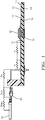
- Figure 1 shows a connection setup from the prior art in a sectional view.
- a semiconductor component 20 is arranged on a printed circuit board 10, the printed circuit board 10 is electrically connected to an electrical conductor 50 via a contact element 40.
- the printed circuit board 10 has a first conductive coating 15 on the first surface 13, a first side 11, and a second conductive coating 16 on a second surface 14, a second side 12.
- the semiconductor component 20 is connected via the electrical conductor 50 , the contact element 40, the conductive coatings 15, 16 with current provided.
- the electrical resistances that oppose the current flow are identified by the reference symbols Rwc, Rcp, Rp, Rpt and Rt. In this illustration it can be clearly seen that the electrical current has to overcome many partial resistances in order to reach the semiconductor components.
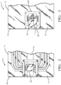
- Figure 2 shows the first page 11 of the inventive connection arrangement.
- a semiconductor component 20 is attached to the first surface 13 and is electrically connected to parts of the first conductive coating 15.
- Figure 3 shows the second side 12 of the inventive connection arrangement.
- the second conductive coating 16 is shown on the second surface 14.
- a connecting means 30 is produced from a portion of the second coating coating 16. This already occurs during the manufacture of the printed circuit board 10.
- the connecting means 30 is produced during the etching or milling of the conductor tracks.
- the shape of the connecting means 30 corresponds to the shape of a contact area 41 of the contact element 40.
- the shape and size of the contact area 41 should be chosen such that the surfaces do not substantially overlap when the contact area 41 is contacted with the connecting means 30. Only where the contact area 41 and the connecting means 30 are connected to one another is electricity and heat optimally transported.
- plated-through holes 17 are shown, which establish an electrical connection between the first electrically conductive coating 15 and the second electrically conductive coating 16.
- the vias 17 are in Figure 2 not visible since they are covered by the semiconductor components 20.
- a holding means 60 which will be explained in more detail later, is also shown in FIG Figure 3 shown.
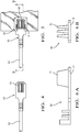
- Figure 4 shows the contact element 40 in a plan view.
- the electrical conductor 50 is connected to the contact element 40 by means of a crimp connection.
- Figure 5 shows the contact element 40 with the electrical conductors 50 attached to it.
- the holding means 60 comprises a clamping profile 61 and an eccentric 62 to which a lever 63 is attached.
- the operation of the holding means 60 is off Figure 7 derivable.
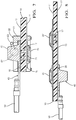
- Figure 6A and 6B show the contact element 40 in side views.
- the flat contact area 41 with which the contact element 40 contacts the connecting means 30 can be seen.
- the contact element 40 has coolant 70 in the form of cooling fins, which extend from the contact area 41, counter to the contact area 41.
- the electrical conductor 50 is attached by means of a crimp connection.
- any known connection technology such as screw connections, soldered or welded connections could be used.
- Figure 7 shows an embodiment of the invention in a sectional view.
- the contact element 40 with the electrical conductor 50 attached to it, is pressed onto the second conductive coating 16 of the circuit board 10 by means of the holding means 60 and is thus electrically contacted via the connecting means 30.
- the contact element 40 and the connecting means 30 are located on the second side 12 of the printed circuit board 10, opposite the semiconductor component 20, which is attached on the first side 11.
- the connecting means 30 has plated-through holes 17 which extend through the printed circuit board 10, from the first conductive coating 15 to the second conductive coating 16 and connect them to one another.
- the semiconductor device 20 has a contact region 21 on the side of the body facing the printed circuit board. The contact region 21 is electrically connected to the first conductive coating 15.
- This structure makes it possible to implement a current path with a low resistance starting from the electrical line 50 to the semiconductor components 20.
- this arrangement offers the possibility of using the contact element 40 and the electrical conductor 50 as cooling elements, since they are in the immediate vicinity, only separated by the printed circuit board, at the heat source (semiconductor component). Due to the close proximity, this arrangement can cool effectively.
- Figure 8 shows an embodiment in which two semiconductor components 20, 20 'are arranged on the first side 11 of the printed circuit board 10.
- the contact element 40 is fixed at a position opposite the first semiconductor component 20.
- the semiconductor component 20 is not intended to control the current that is transported via the electrical conductor 50.
- the contact element 40 is electrically connected to the second semiconductor component 20 ′ via the second conductive coating 16.
- the second semiconductor component 20 ′ controls the current that flows through the electrical conductor 50.
- a semiconductor component 20 is cooled by selecting the position relative to the connecting means 30 and thus the contact element 40, but is not supplied with current.
- the second semiconductor component 20 ′ is supplied with current, but is not cooled by the contact element 40, since it is not opposite the contact element 40. Small compensating heat flows in the conductive coatings 15, 16 are not taken into account here.
Landscapes
- Engineering & Computer Science (AREA)
- Microelectronics & Electronic Packaging (AREA)
- Coupling Device And Connection With Printed Circuit (AREA)
- Cooling Or The Like Of Electrical Apparatus (AREA)
- Multi-Conductor Connections (AREA)
Description
- Die Erfindung betrifft eine elektrische Verbindungsanordnung, zum elektrischen Verbinden eines Kabels und einer Leiterplatte.
- Bei modernen Kraftfahrzeugen, insbesondere Elektrofahrzeugen, sind zum Betrieb der Fahrzeuge große elektrische Ströme notwendig. Diese großen Ströme werden im Kabelsatz des Fahrzeugs durch entsprechend groß dimensionierte Leitungen, zwischen Batterie und Verbraucher, transportiert. Um die elektrischen Verluste, die durch den Widerstand der Leitungen, hervorgerufen werden gering zu halten, werden Leitungen mit großen Querschnitten eingesetzt. Der Einsatz von leichten Aluminiumleitungen erhöht die Leitungsquerschnitte zusätzlich. Die Ströme werden durch Halbleiterbauelemente, die sich in Steuergeräten (ECU) befinden, gesteuert. Der Begriff Steuergerät wird in der Fahrzeugtechnik allgemeinen als Sammelbegriff für, in Gehäusen verteilten, elektrischen Einheiten, verwendet. Die Halbleiterbauelemente sind üblicherweise auf Leiterplatten angeordnet, auf denen sich auch andere elektronische Bauteile befinden. Um die Leiterplatten und die darauf angeordneten Bauelemente mit dem Bordnetz zu verbinden sind üblicherweise Kontaktelemente an der Leiterplatte vorgesehen. Diese können mit Gegenkontakten, die an den Enden der Kabel, des Leitungssatzes angeordnet sind, verbunden werden. In Fahrzeugen ist der Bauraum naturgemäß knapp bemessen. Deshalb sind im Allgemeinen die Kontakte an den Rändern der Leiterplatte angebracht um ein flaches Design des Steuergerätes zu ermöglichen. Dieser Umstand erfordert es, dass die Steckkontakte so ausgeführt werden müssen, dass sie an der Gehäusewand für die Kontakt Teile des Kabelsatzes erreichbar sind. Die Kontaktteile weisen, zum Schutz, eine Umhüllung aus Kunststoff auf. Diese Buchse am Steuergerät wird im Allgemeinen als "Header" bezeichnet. Die Kontaktteile an den Kabelenden des Kabelsatzes sind in einem Steckergehäuse integriert. Diese Art der elektrischen Kontaktierung von Kabelsatz und Steuergerät hat sich in der Fahrzeugtechnik seit vielen Jahren bewährt. Allerdings gelang sie an ihre Grenzen, wenn die zu übertragenen Ströme in Größenordnungen vordringen, wie sie bei Elektrofahrzeugen standardmäßig auftreten. Die Übergangswiderstände an diesen Kontaktsystemen sind signifikant, sie verbrauchen elektrische Energie, die sie in Wärme umwandeln. Kontaktelemente für große Stromdichten weisen bei relativ niedrigen Widerstand großer Abmessungen auf, da der der Widerstand des Strompfads nicht zu groß werden darf. Große Kontaktelemente erfordern große Stecker und entsprechende Buchsen. Dieses vergrößert den Platzbedarf für die Steuergeräte. Ein weiteres Problem findet sich in den Steuergeräten selbst. Dort entsteht, durch die großen Ströme, die durch die elektrischen Bauteile fließen, eine nicht zu unterschätzende Wärmebelastung. Diese Wärme muss über thermisch gut leitfähige Elemente, die an den hitzeerzeugenden Elementen angebracht sind, an das Gehäuse und an die Umgebung geleitet werden. Dokument
DE102010062410A1 offenbart eine verbesserte Wärmesenke zum Abführen von übermäßiger Wärme, die durch die elektronischen Bauelemente auf einer Leiterplatte erzeugt wird. Oder es müssen passive und/oder aktive Lüftungssysteme vorgesehen werden, die Luft zum kühlen in das Gehäuse führen und die erhitzte Luft herausführen. Diese Notwendigkeit zu kühlen macht die Steuergeräte größer, schwerer und teurer. - Der Erfindung liegt die Aufgabe zu Grunde ein Verbindungssystem bereitzustellen, dass bei niedrigem elektrischem Widerstand, die Leitungen eines Kabelsatzes mit der Leiterplatte und den darauf befindlichen elektrischen Bauteilen eines Steuergerätes elektrisch verbindet. Zusätzlich sollte das Verbindungssystem die Kühlung des Steuergerätes unterstützen.
- Die Aufgabe wird durch eine Verbindungsanordnung nach Anspruch 1 gelöst.
- Eine Verbindungsanordnung zum Übertragen großer elektrischer Ströme zum Betrieb von Elektrofahrzeugen, umfassend eine Leiterplatte, ein Halbleiterbauelement angeordnet auf einer ersten Oberfläche einer ersten Seite der Leiterplatte, ein Verbindungsmittel angeordnet auf einer zweiten Oberfläche einer zweiten Seite der Leiterplatte, ein Kontaktelement kontaktierbar mit dem Verbindungsmittel und einer elektrischen Leitung eines Kabelsatzes eines Elektrofahrzeugs, wobei das Verbindungsmittel, gegenüber dem Halbleiterbauelement angeordnet ist. In der Technik verwendete Leiterplatten verwenden ein Aufbau bei dem ein Trägermaterial mit einer elektrisch leitfähigen Beschichtung versehen ist. Es kann eine Seite oder auch beide Seiten elektrisch beschichtet ein. Üblicherweise werden Bereiche die nicht leitfähig sein sollen vom Trägermaterial entfernt. Die Position des Verbindungmittels, das hier aus einem Teil der leitfähigen Beschichtung hergestellt wird, wird auf der Leiterplatte so gewählt, dass es, gegenüber einem Halbleiterbauelement angeordnet ist. Der Begriff "gegenüber", ist hier wie folgt zu verstehen. Das Verbindungsmittel ist so auf der Leiterplatte angeordnet, dass wenn das Trägermaterial der Leiterplatte entfernt werden würde, das Halbleiterbauelement auf dem Verbindungsmittel aufliegen würde. Oder anders ausgedrückt, eine virtuelle Achse, die durch den Mittelpunkt des Halbleiterbauelements und senkrecht durch die Leiterplatte dringt, durchdringt auch das Verbindungsmittel. Dieses hat den Effekt, dass die vom Halbleiterbauelement erzeugte Wärme, durch die Leiterplatte hindurch, auf das Verbindungsmittel geleitet wird. Von dort aus kann die Wärme über das Kontaktelement direkt an die Umgebung abgegeben und auch in den elektrischen Leiter geführt werden. Dadurch kann ein Teil der unerwünschten Wärme aus dem Steuergerät heraus in den Leitungssatz transportiert werden, von wo aus er an die Umwelt abgegeben wird.
- Erfindungsgemäß ist das Verbindungsmittel aus einem Teil der leitfähigen Beschichtung der Leiterplatte gebildet. So ist das Verbindungsmittel bereits nach dem Herstellungsverfahren der Leiterplatte fest mit der Leiterplatte verbunden. Die Geometrie des Verbindungmittels lässt sich leicht auf benötigte Stromdichte und Kontaktelement Geometrie anpassen. Beim Anbringen eines angepassten Kontaktelements an die Leiterplatte wird eine große Fläche des Kontaktelements mit einer großen Fläche der leitfähigen Beschichtung der Leiterplatte elektrisch verbunden. Durch die großflächige Verbindung der beiden, elektrisch leitfähigen, Flächen wird ein niedriger Übergangswiderstand erreicht. An diesem niedrigen Übergangswiderstand wird, auch bei größeren Stromdichten, wenig Wärme erzeugt.
- Besonders bevorzugt ist das Halbleiterbauelement und das gegenüberliegende Verbindungsmitte beabstandet vom Rand der Leiterplatte angeordnet. Die Verbindungsanordnung ermöglicht optimale Design-Freiheit für das Layout der Leiterplatte, da sich die Steckeranschlüsse nicht mehr an den Seiten der Leiterplatte befinden müssen.
- Bevorzugt ist ein zweites Halbleiterbauelement auf der ersten Oberfläche, der ersten Seite, der Leiterplatte angeordnet und elektrisch mit dem Kontaktelement verbindbar. Dadurch kann das erstes Halbleiterbauelement durch das Kontaktelement, das sich gegenüber dem ersten Halbleiterelement befindet, gekühlt werden. Wohingegen das zweite Halbleiterbauelement, das sich nicht gegenüber befindet, mit Strom versorgt wird, ohne gekühlt zu werden. Dadurch wird die thermische Planung der Steuereinheit vereinfacht. Elektrische und thermische Belange können getrennt betrachtet werden.
- Besonders bevorzugt ist das Halbleiterbauelement, zumindest mit einem Teil der leitfähigen Beschichtung, die sich zwischen dem Halbleiterbauelement und Trägermaterial der Leiterplatte erstreckt, elektrisch verbunden. Dadurch läßt sich das thermische und elektrische Verhalten der Schaltung einfacher planen. Die erste leitfähige Beschichtung wird auch zur Wärmeleitung genutzt. Das Halbleiterbauelement kann die Wärme schnell in die leitfähige Beschichtung abgeben. Von dort aus diffundiert die Wärme durch das Trägermaterial zum Verbindungsmittel. Um die Kühlwirkung zu vergrößern kann die erste leitfähige Beschichtung größer, als die Abmessungen des Halbleiterbauelements, gewählt werden. Der Wärmetransport durch das Trägermaterial wird besser je größer die Flächen sind.
- Bevorzugt ist die Fläche des Verbindungsmittels größer als die Fläche der leitfähigen Beschichtung der Leiterplatte, die zwischen Halbleiterbauelement und Trägermaterial angeordnet ist. Dadurch vergrößert sich der Bereich mit einem höheren Wärmeleitwert in der Nähe des Halbleiterbauelements, wodurch der Bereich besser gekühlt wird.
- Bevorzugt weist die Leiterplatte, im Bereich zwischen Halbleiterbauelement und Kontaktelement, mindestens eine Durchkontaktierung. Diese reduziert den elektrischen und thermischen Widerstand zwischen den leitfähigen Beschichtungen der Leiterplatte. Die Durchkontaktierung wird üblicherweise durchgeführt, indem ein Niet, in einer Bohrung des Trägermaterials, der Leiterplatte, befestigt wird. Die Bohrung verläuft üblicherweise senkrecht zu den Flächen. Daraus ergibt sich der kürzeste Weg für Strom und Wärme.
- Besonders bevorzugt weist das Kontaktelement eine ebene Fläche auf, die dazu ausgebildet ist, mit dem Verbindungsmittel eine elektrische Verbindung zu erzeugen. Beim Anbringen des Kontaktelements an die Leiterplatte wird eine große Fläche des Kontaktelements mit einer großen Fläche der leitenden Beschichtung der Leiterplatte elektrisch verbunden. Durch die großflächige Verbindung der beiden, elektrisch leitfähigen, Flächen wird ein niedriger Übergangswiderstand erreicht. An diesem niedrigen Übergangswiderstand wird, auch bei größeren Stromdichten, wenig Wärme erzeugt.
- Bevorzugt weist das Kontaktelement Mittel zur Kühlung auf. Das Kontaktelement kann mittels Fluiden gekühlt werden. Es kann Kühlrippen aufweisen oder massiv ausgebildet sein. Bei massiver Ausgestaltung können Bohrungen oder Kanäle vorgesehen werden, durch die ein Kühlmittel fließen kann. Es können auch thermisch leitfähige Elemente vom Kontaktelement ragen, die mit dem Gehäuse des Steuergerätes oder anderen zur Kühlung verwendeten Elementen verbunden sind. Ein gekühltes Kontaktelement kann die Kühlleistung für ein Halbleiterbauelement zusätzlich erhöhen.
- Bevorzugt weist die Verbindungsanordnung Haltemittel auf, die das Kontaktelement und das Verbindungsmittel lösbar zusammenhalten. Als Haltemittel können alle mechanischen Vorrichtungen dienen, die dazu in der Lage sind das Kontaktelement und das Verbindungsmittel zusammen zu halten. Vorausgesetzt, dass eine gute elektrische und thermische Verbindung gewährleistet ist.
- Besonders bevorzugt ist das Haltemittel so ausgebildet, dass bei Betätigung des Haltemittels, das Kontaktelement gegen das Verbindungsmittel gedrückt wird und ein Teil des Haltemittels gegen das Halbleiterbauelement gedrückt wird. Dadurch wird gewährleistet, dass die Kontaktflächen eng aneinander liegen und einen niedrigen Widerstand aufweisen. Außerdem kühlt das Haltemittel zusätzlich das Halbleiterbauelement.
- Bevorzugt ist das Haltemittel im Querschnitt U-Förmig und an einem der Schenkel ist ein Exzenter angebracht. Der Exzenter ist in den Raum zwischen den Schenkeln schwenkbar. Der Exzenter schwenkt in den Raum zwischen den Schenkeln und drückt Materie, die sich dazwischen befindet, zum gegenüberliegenden Schenkel. Befindet sich zwischen den Schenkeln die Leiterplatte und das Kontaktelement werden diese Teile vom Exzenter gegen den zweiten Schenkel gedrückt. An dem Exzenter ist ein Hebel angebracht mit dem der Exzenter geschwenkt werden kann. Diese Anordnung ist leicht zu bedienen und arbeitet zuverlässig.
- Bevorzugt weist das Haltemittel Mittel zur Kühlung auf. Das Haltemittel kann mittels Fluiden gekühlt werden. Es kann Kühlrippen aufweisen oder massiv ausgebildet sein. Bei massiver Ausgestaltung können Bohrungen oder Kanäle vorgesehen werden, durch die ein Kühlmittel fließen kann. Es können auch thermisch leitfähige Elemente vom Haltemittel ragen, die mit dem Gehäuse des Steuergerätes oder anderen zur Kühlung verwendeten Elementen verbunden sind.
- Bevorzugt ist die Verbindungsanordnung für Hochstromanwendungen geeignet.
- Nachfolgend wird die Erfindung anhand einer vorteilhaften Ausführungsform rein beispielhaft unter Bezugnahme auf die beigefügten Zeichnungen beschrieben. Es zeigen:
-
Fig. 1 zeigt eine Verbindungsanordnung aus dem Stand der Technik. -
Fig. 2 zeigt eine Ansicht auf die erste Seite der Leiterplatte. -
Fig. 3 zeigt eine Ansicht auf die zweite Seite der Leiterplatte. -
Fig. 4 zeigt ein Kontaktelement an dem eine elektrische Leitung befestigt ist. -
Fig. 5 zeigt ein Kontaktelement das an der zweiten Seite der Leiterplatte angebracht ist. -
Fig. 6A zeigt eine Seitenansicht des Kontaktelements. -
Fig. 6B zeigt eine weitere Seitenansicht des Kontaktelements. -
Fig. 7 Zeigt eine Schnittdarstellung derFigur 5 . -
Fig. 8 Zeigt eine Schnittdarstellung einer Leiterplatte mit angebrachtem Kontaktelement und zwei Halbleiterbauelementen. - Im Folgenden werden bevorzugte Ausgestaltungen der Erfindung näher beschrieben. Ähnliche oder korrespondierende Einzelheiten des erfindungsgemäßen Gegenstandes sind mit denselben Bezugszeichen versehen.
-
Figur 1 zeigt ein Verbindungsaufbau aus dem Stand der Technik in einer Schnittdarstellung. Auf einer einer Leiterplatte 10 ist ein Halbleiterbauelement 20 angeordnet, die Leiterplatte 10 ist über ein Kontaktelement 40 mit einem elektrischen Leiter 50 elektrisch verbunden. Die Leiterplatte 10 verfügt auf der ersten Oberfläche 13, einer ersten Seite 11, über eine erste leitfähige Beschichtung 15. Sowie auf einer zweiten Oberfläche 14, einer zweiten Seite 12, über eine zweite leitfähige Beschichtung 16. Das Halbleiterbauelement 20 wird über den elektrischen Leiter 50, das Kontaktelement 40, die leitfähigen Beschichtungen 15,16 mit Strom versorgt. Die elektrischen Widerstände, die sich dem Stromfluss entgegen setzen, sind mit dem Bezugszeichen Rwc, Rcp, Rp, Rpt und Rt bezeichnet. In dieser Darstellung ist gut zu sehen, dass der elektrische Strom viele Teilwiderstände überwinden muss um das Halbleiter Bauelemente zu erreichen. -
Figur 2 zeigt die erste Seite 11 der erfinderischen Verbindungsanordnung. Auf der ersten Oberfläche 13 ist ein Halbleiterbauelement 20 angebracht und mit Teilen der ersten leitfähigen Beschichtung 15 elektrisch verbunden. -
Figur 3 zeigt die zweite Seite 12 der erfinderischen Verbindungsanordnung. Auf der zweiten Oberfläche 14 ist die zweite leitfähige Beschichtung 16 dargestellt. Aus einem Teilbereich der zweiten Leitfäden Beschichtung 16 wird ein Verbindungsmittel 30 erzeugt. Dieses passiert schon bei der Herstellung der Leiterplatte 10. Das Verbindungsmittel 30 wird beim Ätzen oder Fräsen der Leiterbahnen erzeugt. Die Form des Verbindungmittels 30 korrespondiert mit der Form eines Kontaktbereichs 41 des Kontaktelements 40. Die Form und Größe des Kontaktbereichs 41 sollte so gewählt werden, dass die Oberflächen nicht wesentlich überlappen, wenn der Kontaktbereich 41 mit dem Verbindungsmittel 30 kontaktiert wird. Nur dort wo Kontaktbereich 41 und Verbindungsmittel 30 miteinander verbunden sind, wird optimal Strom und Wärme transportiert. - Im Bereich des Verbindungmittels 30 sind Durchkontaktierungen 17 dargestellt, die eine elektrische Verbindung zwischen der ersten elektrisch leitfähigen Beschichtung 15 und der zweiten elektrisch leitfähigen Beschichtung 16 herstellen. Die Durchkontaktierungen 17 sind in
Figur 2 nicht sichtbar, da sie vom Halbleiterbauelemente 20 verdeckt sind. Ein Haltemittel 60, das später genauer erläutert wird, ist ebenfalls inFigur 3 dargestellt. -
Figur 4 zeigt das Kontaktelement 40 in einer Draufsicht. Der elektrische Leiter 50 ist mit dem Kontaktelement 40 mittels einer Crimp-Verbindung verbunden. -
Figur 5 zeigt das Kontaktelement 40 mit dem daran befestigten elektrischen Leitern 50. Das Haltemittel 60 umfasst ein Klemmprofil 61 sowie ein Exzenter 62, an dem ein Hebel 63 angebracht ist. Die Funktionsweise des Haltemittels 60 ist ausFigur 7 ableitbar. -
Figur 6A und 6B zeigen das Kontaktelement 40 in seitlichen Ansichten. Zu sehen ist der ebene Kontaktbereich 41 mit dem das Kontaktelement 40 das Verbindungsmittel 30 kontaktiert. Das Kontaktelement 40 verfügt in dieser Ausführungsform über Kühlmittel 70 in Form von Kühlrippen, die sich vom Kontaktbereich 41, entgegen des Kontaktbereichs 41, erstrecken. Im Anschlussbereich des Kontaktelements 40, der zur Verbindung mit einem Leitungssatz vorgesehen ist, ist mittels einer Crimp-Verbindung der elektrischer Leiter 50 angebracht. Es könnte allerdings jede bekannte Verbindungstechnik wie, Schraubverbindungen, Löt-oder-Schweißverbindungen, verwendet werden. -
Figur 7 zeigt eine Ausführungsform der Erfindung in Schnittdarstellung. Das Kontaktelement 40, mit dem daran befestigtem elektrischen Leiter 50, wird mittels des Haltemittels 60 auf die zweite leitfähige Beschichtung 16 der Leiterplatte 10 gedrückt und so über das Verbindungsmittel 30 elektrisch kontaktiert. Das Kontaktelement 40 und das Verbindungsmittel 30 befinden sich auf der zweiten Seite 12 der Leiterplatte 10, gegenüber dem Halbleiterbauelemente 20, das auf der ersten Seite 11 angebracht ist. Das Verbindungsmittel 30 weist Durchkontaktierungen 17 auf, die sich durch die Leiterplatte 10 hindurch, von der ersten leitfähigen Beschichtung 15 zur zweiten leitfähigen Beschichtung 16 erstrecken und diese miteinander verbinden. Das Halbleiterbauelement 20 weist einen Kontaktbereich 21 an der, der Leiterplatte zugewandten Seite, seines Körpers auf. Der Kontaktbereich 21 ist elektrisch mit der ersten leitfähigen Beschichtung 15 verbunden. Dieser Aufbau macht es möglich einen Strompfad, ausgehend von der elektrischen Leitung 50, bis zum Halbleiterbauelemente 20, mit niedrigem Widerstand zu realisieren. Außerdem bietet diese Anordnung die Möglichkeit, das Kontaktelement 40 und den elektrischen Leiter 50 als Kühlelemente zu benutzen, da sie sich in unmittelbarer Nähe, nur durch die Leiterplatte getrennt, an der Wärmequelle (Halbleiterbauelement) befinden. Durch die räumliche Nähe kann diese Anordnung effektiv kühlen. -
Figur 8 zeigt einer Ausführungsform, bei der zwei Halbleiterbauelemente 20, 20' auf der ersten Seite 11, der Leiterplatte 10 angeordnet sind. Das Kontaktelement 40 ist an einer Position gegenüber dem ersten Halbleiterbauelemente 20 befestigt. Das Halbleiterbauelement 20 ist allerdings nicht dafür vorgesehen den Strom, der über den elektrischen Leiter 50 transportiert wird zu steuern. Das Kontaktelement 40 ist über die zweite leitfähige Beschichtung 16 mit dem zweiten Halbleiterbauelemente 20' elektrisch verbunden. Das zweite Halbleiterbauelement 20' steuert den Strom der durch den elektrischen Leiter 50 fließt. In dieser Ausführungsform wird ein Halbleiterbauelement 20 durch Auswahl der Position gegenüber dem Verbindungsmittel 30 und somit Kontaktelement 40 gekühlt, jedoch nicht mit Strom versorgt. Das zweite Halbleiterbauelement 20' wird mit Strom versorgt allerdings nicht vom Kontaktelement 40 gekühlt, da es sich nicht gegenüber dem Kontaktelement 40 befindet. Hierbei werden kleinere ausgleichende Wärmeflüsse in den leitfähigen Beschichtungen 15, 16 nicht berücksichtigt.
Claims (13)
- Verbindungsanordnung (1) zum Übertragen großer elektrischer Ströme zum Betrieb von Elektrofahrzeugen, umfassend eine Leiterplatte (10), ein Halbleiterbauelement (20) angeordnet auf einer ersten Oberfläche (13) einer ersten Seite (11) der Leiterplatte (10), ein Verbindungsmittel (30) angeordnet auf einer zweiten Oberfläche (14) einer zweiten Seite (12) der Leiterplatte (10), sowie ein Kontaktelement (40) kontaktierbar mit dem Verbindungsmittel (30) und einer elektrischen Leitung (50) eines Kabelsatzes eines Elektrofahrzeugs, wobei das Verbindungsmittel (30) gegenüber dem Halbleiterbauelement (20) angeordnet ist, und wobei die erste Oberfläche (13) eine erste leitfähige Beschichtung (15) aufweist, dadurch gekennzeichnet, dass das Verbindungsmittel (30) aus einem Teil einer zweiten leitfähigen Beschichtung (16) der zweiten Oberfläche (14) gebildet ist.
- Verbindungsanordnung (1) nach Anspruch 1, wobei das Halbleiterbauelement (20) und das gegenüberliegende Verbindungsmittel (30) beabstandet vom Rand der Leiterplatte (10) angeordnet sind.
- Verbindungsanordnung (1) nach einem der vorhergehenden Ansprüche, wobei ein zweites Halbleiterbauelement (20') auf der ersten Oberfläche (13), der ersten Seite (11), der Leiterplatte (10) angeordnet ist und elektrisch direkt mit dem Kontaktelement (40) verbindbar ist.
- Verbindungsanordnung (1), nach einem der vorhergehenden Ansprüche, wobei das Halbleiterbauelement (20), zumindest mit einem Teil der ersten leitfähigen Beschichtung (15), die sich zwischen dem Halbleiterbauelement (20) und Trägermaterial der Leiterplatte (10) erstreckt, elektrisch verbunden ist.
- Verbindungsanordnung (1) nach Anspruch 1, wobei eine Fläche, des Verbindungsmittels (30) größer ist als eine Fläche der leitfähigen Beschichtung (15) der Leiterplatte (10), die zwischen Halbleiterbauelement (20) und Trägermaterial angeordnet ist.
- Verbindungsanordnung (1) nach einem der vorhergehenden Ansprüche, wobei die Leiterplatte (10) im Bereich zwischen Halbleiterbauelement (20) und Verbindungsmittel (30), mindestens eine Durchkontaktierung (17) aufweist.
- Verbindungsanordnung (1) nach einem der vorhergehenden Ansprüche, wobei das Kontaktelement (40) eine ebene Fläche (41) aufweist, die dazu ausgebildet ist mit dem Verbindungsmittel (30) eine elektrische Verbindung zu erzeugen.
- Verbindungsanordnung (1) nach einem der vorhergehenden Ansprüche, wobei das Kontaktelement (40) Mittel zur Kühlung (70) aufweist.
- Verbindungsanordnung (1) nach einem der vorhergehenden Ansprüche, wobei die Verbindungsanordnung Haltemittel (60) aufweist, die das Kontaktelement (40) und das Verbindungsmittel (30) lösbar zusammenhalten.
- Verbindungsanordnung (1) nach Anspruch 9, wobei das Haltemittel (60), so ausgebildet ist, dass bei Betätigung des Haltemittels (60), das Kontaktelement (40) gegen das Verbindungsmittel (30) gedrückt wird und ein Teil des Haltemittels (60) gegen das Halbleiterbauelement (20) gedrückt wird.
- Verbindungsanordnung (1) nach Anspruch 10 wobei das Haltemittel (60) im Querschnitt U-Förmig ist und an einem Schenkel ein Exzenter (62), angebracht ist, das in den Raum zwischen den Schenkeln, schwenkbar ist.
- Verbindungsanordnung (1) nach Anspruch 9 bis 11, wobei das Haltemittel (60) Mittel zur Kühlung aufweist.
- Verbindungsanordnung (1) nach einem der vorhergehenden Ansprüche, wobei die Verbindungsanordnung (1) für Hochstromanwendungen geeignet ist.
Priority Applications (3)
| Application Number | Priority Date | Filing Date | Title |
|---|---|---|---|
| EP14179926.2A EP2983246B1 (de) | 2014-08-05 | 2014-08-05 | Elektrische Verbindungsanordnung |
| US14/817,791 US9620873B2 (en) | 2014-08-05 | 2015-08-04 | Electrical connection arrangement |
| CN201510581462.1A CN105337100B (zh) | 2014-08-05 | 2015-08-05 | 电连接装置 |
Applications Claiming Priority (1)
| Application Number | Priority Date | Filing Date | Title |
|---|---|---|---|
| EP14179926.2A EP2983246B1 (de) | 2014-08-05 | 2014-08-05 | Elektrische Verbindungsanordnung |
Publications (2)
| Publication Number | Publication Date |
|---|---|
| EP2983246A1 EP2983246A1 (de) | 2016-02-10 |
| EP2983246B1 true EP2983246B1 (de) | 2020-03-04 |
Family
ID=51263333
Family Applications (1)
| Application Number | Title | Priority Date | Filing Date |
|---|---|---|---|
| EP14179926.2A Active EP2983246B1 (de) | 2014-08-05 | 2014-08-05 | Elektrische Verbindungsanordnung |
Country Status (3)
| Country | Link |
|---|---|
| US (1) | US9620873B2 (de) |
| EP (1) | EP2983246B1 (de) |
| CN (1) | CN105337100B (de) |
Families Citing this family (5)
| Publication number | Priority date | Publication date | Assignee | Title |
|---|---|---|---|---|
| DE102016105311A1 (de) * | 2016-03-22 | 2017-09-28 | Phoenix Contact E-Mobility Gmbh | Steckverbinderteil mit einem gekühlten Kontaktelement |
| DE102016105347A1 (de) * | 2016-03-22 | 2017-09-28 | Phoenix Contact E-Mobility Gmbh | Steckverbinderteil mit einem gekühlten Kontaktelement |
| EP3297097A1 (de) * | 2016-09-16 | 2018-03-21 | Delphi Technologies, Inc. | Kontaktelement für eine leiterplatte |
| JP2019047029A (ja) * | 2017-09-05 | 2019-03-22 | 矢崎総業株式会社 | 回路基板の放熱構造 |
| US11285832B2 (en) * | 2019-06-05 | 2022-03-29 | TE Connectivity Services Gmbh | Heat exchanger for a power connector |
Citations (1)
| Publication number | Priority date | Publication date | Assignee | Title |
|---|---|---|---|---|
| DE102010062410A1 (de) * | 2010-02-11 | 2011-08-11 | Lear Corporation, Mich. | Elektrischer Stecker und Wärmesenke |
Family Cites Families (23)
| Publication number | Priority date | Publication date | Assignee | Title |
|---|---|---|---|---|
| US4420206A (en) * | 1981-11-30 | 1983-12-13 | Western Electric Company, Inc. | Electrical connector |
| US4645943A (en) * | 1984-10-15 | 1987-02-24 | Dallas Semiconductor Corporation | Space-saving back-up power supply |
| US4935864A (en) * | 1989-06-20 | 1990-06-19 | Digital Equipment Corporation | Localized cooling apparatus for cooling integrated circuit devices |
| US5469330A (en) * | 1994-02-14 | 1995-11-21 | Karabatsos; Chris | Heat sink header assembly |
| US5470795A (en) * | 1994-02-25 | 1995-11-28 | Shushurin; Vladimir V. | Method of connecting terminals of a plastic-encapsulated power transistor to a printed-circuit board |
| TW381328B (en) * | 1994-03-07 | 2000-02-01 | Ibm | Dual substrate package assembly for being electrically coupled to a conducting member |
| US6018465A (en) * | 1996-12-31 | 2000-01-25 | Intel Corporation | Apparatus for mounting a chip package to a chassis of a computer |
| CA2225235A1 (en) * | 1997-12-19 | 1999-06-19 | Northern Telecom Limited | A line interface module |
| US6166464A (en) * | 1998-08-24 | 2000-12-26 | International Rectifier Corp. | Power module |
| JP4131935B2 (ja) * | 2003-02-18 | 2008-08-13 | 株式会社東芝 | インターフェイスモジュールとインターフェイスモジュール付lsiパッケージ及びその実装方法 |
| US8068346B2 (en) * | 2004-05-04 | 2011-11-29 | Hamilton Sundstrand Corporation | Circuit board with high density power semiconductors |
| CN2821902Y (zh) * | 2005-06-29 | 2006-09-27 | 富士康(昆山)电脑接插件有限公司 | 电连接器组件 |
| US8657031B2 (en) * | 2005-10-12 | 2014-02-25 | Black & Decker Inc. | Universal control module |
| FR2895204B1 (fr) * | 2005-12-21 | 2008-06-06 | Valeo Systemes Thermiques | Optimisation d'un dispositif de chauffage |
| US7233502B1 (en) * | 2006-03-15 | 2007-06-19 | Universal Scientific Industrial Co., Ltd. | Twin-substrate wireless electronic module and method for making the same |
| US7510418B1 (en) * | 2007-10-31 | 2009-03-31 | Intel Corporation | Loading mechanisms for integrated circuit (IC) packages |
| CN201126880Y (zh) * | 2007-12-25 | 2008-10-01 | 上海徕木电子有限公司 | 一种电子线路板的连接器 |
| DE102008040290A1 (de) * | 2008-07-09 | 2010-01-14 | Robert Bosch Gmbh | Hybridschaltungsstruktur mit keramischen Schaltungsträgern |
| TWI387090B (zh) * | 2009-06-05 | 2013-02-21 | 華東科技股份有限公司 | Reverse staggered stack structure of integrated circuit module |
| US8724339B2 (en) * | 2009-12-01 | 2014-05-13 | Apple Inc. | Compact media player |
| TWI406390B (zh) * | 2010-02-26 | 2013-08-21 | Walton Advanced Eng Inc | High density integrated circuit module structure |
| US8572840B2 (en) * | 2010-09-30 | 2013-11-05 | International Business Machines Corporation | Method of attaching an electronic module power supply |
| JP5582995B2 (ja) * | 2010-12-14 | 2014-09-03 | 新光電気工業株式会社 | ソケット |
-
2014
- 2014-08-05 EP EP14179926.2A patent/EP2983246B1/de active Active
-
2015
- 2015-08-04 US US14/817,791 patent/US9620873B2/en active Active
- 2015-08-05 CN CN201510581462.1A patent/CN105337100B/zh active Active
Patent Citations (1)
| Publication number | Priority date | Publication date | Assignee | Title |
|---|---|---|---|---|
| DE102010062410A1 (de) * | 2010-02-11 | 2011-08-11 | Lear Corporation, Mich. | Elektrischer Stecker und Wärmesenke |
Also Published As
| Publication number | Publication date |
|---|---|
| US20160043485A1 (en) | 2016-02-11 |
| EP2983246A1 (de) | 2016-02-10 |
| CN105337100B (zh) | 2017-12-19 |
| CN105337100A (zh) | 2016-02-17 |
| US9620873B2 (en) | 2017-04-11 |
Similar Documents
| Publication | Publication Date | Title |
|---|---|---|
| DE102013225411B4 (de) | Verbinder für eine LED-Modulplatine und Kombination aus Verbinder und LED- Modulplatine | |
| DE102015103096B4 (de) | Kühleinrichtung und Kühlanordnung mit der Kühleinrichtung | |
| EP2983246B1 (de) | Elektrische Verbindungsanordnung | |
| DE102017219229B4 (de) | Verzweigungsstruktur und Kabelbaum | |
| DE112006002302B4 (de) | Elektrisches system umfassend eine leistungstransistoranordnung, eine stromschiene und eine leiterplattenbaugruppe | |
| DE102010062410A1 (de) | Elektrischer Stecker und Wärmesenke | |
| DE102015104297B4 (de) | Fixierelement zum Anbinden einer Platine, Stromschiene und damit ausgestatteter Stromverteiler eines Fahrzeugs | |
| DE102011088322B4 (de) | VERBINDUNGSSYSTEM ZUM ELEKTRISCHEN ANSCHLIEßEN ELEKTRISCHER GERÄTE, LEISTUNGSHALBLEITERMODULSYSTEM, VERFAHREN ZUM VERBINDEN EINES ELEKTRISCH LEITENDEN ERSTEN ANSCHLUSSES UND EINES ELEKTRISCH LEITENDEN ZWEITEN ANSCHLUSSES, UND VERFAHREN ZUR HERSTELLUNG | |
| EP3095307B1 (de) | Leiterplatte, schaltung und verfahren zur herstellung einer schaltung | |
| DE102012216694A1 (de) | Elektrische Verbindung mit Kühlung zur Wärmeableitung | |
| DE112015002187T5 (de) | Schaltungsbaugruppe und elektrischer Verteiler | |
| DE102013221635A1 (de) | Elektronisches Gerät | |
| DE19518522C2 (de) | Steuergerät für ein Kraftfahrzeug | |
| DE102014203737B4 (de) | Elektronisches teil und elektronische steuereinheit | |
| DE112016004181T5 (de) | Schaltungsanordnung und elektrischer Verteilerkasten | |
| EP2716145B1 (de) | Leiterplatte für elektrische bauelemente und leiterplattensystem | |
| DE102013007167B4 (de) | Hochstromsteckverbindung mit Wärmeabfuhrelementen | |
| DE102012000907B4 (de) | Elektrogerät | |
| EP2006910A2 (de) | Leistungselektronikmodul | |
| DE102015220096B4 (de) | Elektrische Kontaktverbindung und elektrischer Kontakt | |
| DE102017125687B3 (de) | Dezentraler kleinverteiler, leitungssystem und herstellverfahren | |
| EP3251472B1 (de) | Elektrogerät, baureihe von elektrogeräten und verfahren zur herstellung | |
| EP3881652A1 (de) | Schaltungsträger, (leistungs-)elektronikanordnung und elektrische antriebsvorrichtung | |
| DE102012216694B4 (de) | Kontaktsystem | |
| DE102020216305B4 (de) | Elektrische Schaltvorrichtung |
Legal Events
| Date | Code | Title | Description |
|---|---|---|---|
| PUAI | Public reference made under article 153(3) epc to a published international application that has entered the european phase |
Free format text: ORIGINAL CODE: 0009012 |
|
| AK | Designated contracting states |
Kind code of ref document: A1 Designated state(s): AL AT BE BG CH CY CZ DE DK EE ES FI FR GB GR HR HU IE IS IT LI LT LU LV MC MK MT NL NO PL PT RO RS SE SI SK SM TR |
|
| AX | Request for extension of the european patent |
Extension state: BA ME |
|
| 17P | Request for examination filed |
Effective date: 20160810 |
|
| RBV | Designated contracting states (corrected) |
Designated state(s): AL AT BE BG CH CY CZ DE DK EE ES FI FR GB GR HR HU IE IS IT LI LT LU LV MC MK MT NL NO PL PT RO RS SE SI SK SM TR |
|
| STAA | Information on the status of an ep patent application or granted ep patent |
Free format text: STATUS: EXAMINATION IS IN PROGRESS |
|
| 17Q | First examination report despatched |
Effective date: 20180105 |
|
| RAP1 | Party data changed (applicant data changed or rights of an application transferred) |
Owner name: APTIV TECHNOLOGIES LIMITED |
|
| GRAP | Despatch of communication of intention to grant a patent |
Free format text: ORIGINAL CODE: EPIDOSNIGR1 |
|
| STAA | Information on the status of an ep patent application or granted ep patent |
Free format text: STATUS: GRANT OF PATENT IS INTENDED |
|
| RIC1 | Information provided on ipc code assigned before grant |
Ipc: H01R 12/70 20110101ALN20190820BHEP Ipc: H01R 12/88 20110101ALN20190820BHEP Ipc: H01R 12/71 20110101AFI20190820BHEP Ipc: H01R 12/75 20110101ALI20190820BHEP Ipc: H05K 1/02 20060101ALI20190820BHEP |
|
| INTG | Intention to grant announced |
Effective date: 20190918 |
|
| GRAS | Grant fee paid |
Free format text: ORIGINAL CODE: EPIDOSNIGR3 |
|
| GRAA | (expected) grant |
Free format text: ORIGINAL CODE: 0009210 |
|
| STAA | Information on the status of an ep patent application or granted ep patent |
Free format text: STATUS: THE PATENT HAS BEEN GRANTED |
|
| AK | Designated contracting states |
Kind code of ref document: B1 Designated state(s): AL AT BE BG CH CY CZ DE DK EE ES FI FR GB GR HR HU IE IS IT LI LT LU LV MC MK MT NL NO PL PT RO RS SE SI SK SM TR |
|
| REG | Reference to a national code |
Ref country code: GB Ref legal event code: FG4D Free format text: NOT ENGLISH |
|
| REG | Reference to a national code |
Ref country code: CH Ref legal event code: EP |
|
| REG | Reference to a national code |
Ref country code: AT Ref legal event code: REF Ref document number: 1241452 Country of ref document: AT Kind code of ref document: T Effective date: 20200315 |
|
| REG | Reference to a national code |
Ref country code: DE Ref legal event code: R096 Ref document number: 502014013727 Country of ref document: DE |
|
| REG | Reference to a national code |
Ref country code: IE Ref legal event code: FG4D Free format text: LANGUAGE OF EP DOCUMENT: GERMAN |
|
| PG25 | Lapsed in a contracting state [announced via postgrant information from national office to epo] |
Ref country code: NO Free format text: LAPSE BECAUSE OF FAILURE TO SUBMIT A TRANSLATION OF THE DESCRIPTION OR TO PAY THE FEE WITHIN THE PRESCRIBED TIME-LIMIT Effective date: 20200604 Ref country code: FI Free format text: LAPSE BECAUSE OF FAILURE TO SUBMIT A TRANSLATION OF THE DESCRIPTION OR TO PAY THE FEE WITHIN THE PRESCRIBED TIME-LIMIT Effective date: 20200304 Ref country code: RS Free format text: LAPSE BECAUSE OF FAILURE TO SUBMIT A TRANSLATION OF THE DESCRIPTION OR TO PAY THE FEE WITHIN THE PRESCRIBED TIME-LIMIT Effective date: 20200304 |
|
| REG | Reference to a national code |
Ref country code: NL Ref legal event code: MP Effective date: 20200304 |
|
| PG25 | Lapsed in a contracting state [announced via postgrant information from national office to epo] |
Ref country code: GR Free format text: LAPSE BECAUSE OF FAILURE TO SUBMIT A TRANSLATION OF THE DESCRIPTION OR TO PAY THE FEE WITHIN THE PRESCRIBED TIME-LIMIT Effective date: 20200605 Ref country code: SE Free format text: LAPSE BECAUSE OF FAILURE TO SUBMIT A TRANSLATION OF THE DESCRIPTION OR TO PAY THE FEE WITHIN THE PRESCRIBED TIME-LIMIT Effective date: 20200304 Ref country code: LV Free format text: LAPSE BECAUSE OF FAILURE TO SUBMIT A TRANSLATION OF THE DESCRIPTION OR TO PAY THE FEE WITHIN THE PRESCRIBED TIME-LIMIT Effective date: 20200304 Ref country code: HR Free format text: LAPSE BECAUSE OF FAILURE TO SUBMIT A TRANSLATION OF THE DESCRIPTION OR TO PAY THE FEE WITHIN THE PRESCRIBED TIME-LIMIT Effective date: 20200304 Ref country code: BG Free format text: LAPSE BECAUSE OF FAILURE TO SUBMIT A TRANSLATION OF THE DESCRIPTION OR TO PAY THE FEE WITHIN THE PRESCRIBED TIME-LIMIT Effective date: 20200604 |
|
| REG | Reference to a national code |
Ref country code: LT Ref legal event code: MG4D |
|
| PG25 | Lapsed in a contracting state [announced via postgrant information from national office to epo] |
Ref country code: NL Free format text: LAPSE BECAUSE OF FAILURE TO SUBMIT A TRANSLATION OF THE DESCRIPTION OR TO PAY THE FEE WITHIN THE PRESCRIBED TIME-LIMIT Effective date: 20200304 |
|
| PG25 | Lapsed in a contracting state [announced via postgrant information from national office to epo] |
Ref country code: EE Free format text: LAPSE BECAUSE OF FAILURE TO SUBMIT A TRANSLATION OF THE DESCRIPTION OR TO PAY THE FEE WITHIN THE PRESCRIBED TIME-LIMIT Effective date: 20200304 Ref country code: LT Free format text: LAPSE BECAUSE OF FAILURE TO SUBMIT A TRANSLATION OF THE DESCRIPTION OR TO PAY THE FEE WITHIN THE PRESCRIBED TIME-LIMIT Effective date: 20200304 Ref country code: SK Free format text: LAPSE BECAUSE OF FAILURE TO SUBMIT A TRANSLATION OF THE DESCRIPTION OR TO PAY THE FEE WITHIN THE PRESCRIBED TIME-LIMIT Effective date: 20200304 Ref country code: ES Free format text: LAPSE BECAUSE OF FAILURE TO SUBMIT A TRANSLATION OF THE DESCRIPTION OR TO PAY THE FEE WITHIN THE PRESCRIBED TIME-LIMIT Effective date: 20200304 Ref country code: IS Free format text: LAPSE BECAUSE OF FAILURE TO SUBMIT A TRANSLATION OF THE DESCRIPTION OR TO PAY THE FEE WITHIN THE PRESCRIBED TIME-LIMIT Effective date: 20200704 Ref country code: CZ Free format text: LAPSE BECAUSE OF FAILURE TO SUBMIT A TRANSLATION OF THE DESCRIPTION OR TO PAY THE FEE WITHIN THE PRESCRIBED TIME-LIMIT Effective date: 20200304 Ref country code: RO Free format text: LAPSE BECAUSE OF FAILURE TO SUBMIT A TRANSLATION OF THE DESCRIPTION OR TO PAY THE FEE WITHIN THE PRESCRIBED TIME-LIMIT Effective date: 20200304 Ref country code: PT Free format text: LAPSE BECAUSE OF FAILURE TO SUBMIT A TRANSLATION OF THE DESCRIPTION OR TO PAY THE FEE WITHIN THE PRESCRIBED TIME-LIMIT Effective date: 20200729 Ref country code: SM Free format text: LAPSE BECAUSE OF FAILURE TO SUBMIT A TRANSLATION OF THE DESCRIPTION OR TO PAY THE FEE WITHIN THE PRESCRIBED TIME-LIMIT Effective date: 20200304 |
|
| REG | Reference to a national code |
Ref country code: DE Ref legal event code: R097 Ref document number: 502014013727 Country of ref document: DE |
|
| PLBE | No opposition filed within time limit |
Free format text: ORIGINAL CODE: 0009261 |
|
| STAA | Information on the status of an ep patent application or granted ep patent |
Free format text: STATUS: NO OPPOSITION FILED WITHIN TIME LIMIT |
|
| PG25 | Lapsed in a contracting state [announced via postgrant information from national office to epo] |
Ref country code: DK Free format text: LAPSE BECAUSE OF FAILURE TO SUBMIT A TRANSLATION OF THE DESCRIPTION OR TO PAY THE FEE WITHIN THE PRESCRIBED TIME-LIMIT Effective date: 20200304 Ref country code: IT Free format text: LAPSE BECAUSE OF FAILURE TO SUBMIT A TRANSLATION OF THE DESCRIPTION OR TO PAY THE FEE WITHIN THE PRESCRIBED TIME-LIMIT Effective date: 20200304 |
|
| 26N | No opposition filed |
Effective date: 20201207 |
|
| PG25 | Lapsed in a contracting state [announced via postgrant information from national office to epo] |
Ref country code: SI Free format text: LAPSE BECAUSE OF FAILURE TO SUBMIT A TRANSLATION OF THE DESCRIPTION OR TO PAY THE FEE WITHIN THE PRESCRIBED TIME-LIMIT Effective date: 20200304 Ref country code: PL Free format text: LAPSE BECAUSE OF FAILURE TO SUBMIT A TRANSLATION OF THE DESCRIPTION OR TO PAY THE FEE WITHIN THE PRESCRIBED TIME-LIMIT Effective date: 20200304 |
|
| PG25 | Lapsed in a contracting state [announced via postgrant information from national office to epo] |
Ref country code: MC Free format text: LAPSE BECAUSE OF FAILURE TO SUBMIT A TRANSLATION OF THE DESCRIPTION OR TO PAY THE FEE WITHIN THE PRESCRIBED TIME-LIMIT Effective date: 20200304 |
|
| REG | Reference to a national code |
Ref country code: CH Ref legal event code: PL |
|
| PG25 | Lapsed in a contracting state [announced via postgrant information from national office to epo] |
Ref country code: LU Free format text: LAPSE BECAUSE OF NON-PAYMENT OF DUE FEES Effective date: 20200805 Ref country code: LI Free format text: LAPSE BECAUSE OF NON-PAYMENT OF DUE FEES Effective date: 20200831 Ref country code: CH Free format text: LAPSE BECAUSE OF NON-PAYMENT OF DUE FEES Effective date: 20200831 |
|
| REG | Reference to a national code |
Ref country code: BE Ref legal event code: MM Effective date: 20200831 |
|
| PG25 | Lapsed in a contracting state [announced via postgrant information from national office to epo] |
Ref country code: BE Free format text: LAPSE BECAUSE OF NON-PAYMENT OF DUE FEES Effective date: 20200831 Ref country code: IE Free format text: LAPSE BECAUSE OF NON-PAYMENT OF DUE FEES Effective date: 20200805 |
|
| REG | Reference to a national code |
Ref country code: AT Ref legal event code: MM01 Ref document number: 1241452 Country of ref document: AT Kind code of ref document: T Effective date: 20200805 |
|
| PG25 | Lapsed in a contracting state [announced via postgrant information from national office to epo] |
Ref country code: AT Free format text: LAPSE BECAUSE OF NON-PAYMENT OF DUE FEES Effective date: 20200805 |
|
| PG25 | Lapsed in a contracting state [announced via postgrant information from national office to epo] |
Ref country code: TR Free format text: LAPSE BECAUSE OF FAILURE TO SUBMIT A TRANSLATION OF THE DESCRIPTION OR TO PAY THE FEE WITHIN THE PRESCRIBED TIME-LIMIT Effective date: 20200304 Ref country code: MT Free format text: LAPSE BECAUSE OF FAILURE TO SUBMIT A TRANSLATION OF THE DESCRIPTION OR TO PAY THE FEE WITHIN THE PRESCRIBED TIME-LIMIT Effective date: 20200304 Ref country code: CY Free format text: LAPSE BECAUSE OF FAILURE TO SUBMIT A TRANSLATION OF THE DESCRIPTION OR TO PAY THE FEE WITHIN THE PRESCRIBED TIME-LIMIT Effective date: 20200304 |
|
| PG25 | Lapsed in a contracting state [announced via postgrant information from national office to epo] |
Ref country code: MK Free format text: LAPSE BECAUSE OF FAILURE TO SUBMIT A TRANSLATION OF THE DESCRIPTION OR TO PAY THE FEE WITHIN THE PRESCRIBED TIME-LIMIT Effective date: 20200304 Ref country code: AL Free format text: LAPSE BECAUSE OF FAILURE TO SUBMIT A TRANSLATION OF THE DESCRIPTION OR TO PAY THE FEE WITHIN THE PRESCRIBED TIME-LIMIT Effective date: 20200304 |
|
| P01 | Opt-out of the competence of the unified patent court (upc) registered |
Effective date: 20230424 |
|
| PGFP | Annual fee paid to national office [announced via postgrant information from national office to epo] |
Ref country code: DE Payment date: 20240723 Year of fee payment: 11 |
|
| PGFP | Annual fee paid to national office [announced via postgrant information from national office to epo] |
Ref country code: GB Payment date: 20240731 Year of fee payment: 11 |
|
| PGFP | Annual fee paid to national office [announced via postgrant information from national office to epo] |
Ref country code: FR Payment date: 20240730 Year of fee payment: 11 |
|
| REG | Reference to a national code |
Ref country code: DE Ref legal event code: R081 Ref document number: 502014013727 Country of ref document: DE Owner name: APTIV TECHNOLOGIES AG, CH Free format text: FORMER OWNER: APTIV TECHNOLOGIES LIMITED, ST. MICHAEL, BB |