EP2982635A1 - Device for checking working state of work machine - Google Patents
Device for checking working state of work machine Download PDFInfo
- Publication number
- EP2982635A1 EP2982635A1 EP14779033.1A EP14779033A EP2982635A1 EP 2982635 A1 EP2982635 A1 EP 2982635A1 EP 14779033 A EP14779033 A EP 14779033A EP 2982635 A1 EP2982635 A1 EP 2982635A1
- Authority
- EP
- European Patent Office
- Prior art keywords
- work state
- information regarding
- work
- load factor
- current
- Prior art date
- Legal status (The legal status is an assumption and is not a legal conclusion. Google has not performed a legal analysis and makes no representation as to the accuracy of the status listed.)
- Granted
Links
Images



Classifications
-
- B—PERFORMING OPERATIONS; TRANSPORTING
- B66—HOISTING; LIFTING; HAULING
- B66C—CRANES; LOAD-ENGAGING ELEMENTS OR DEVICES FOR CRANES, CAPSTANS, WINCHES, OR TACKLES
- B66C23/00—Cranes comprising essentially a beam, boom, or triangular structure acting as a cantilever and mounted for translatory of swinging movements in vertical or horizontal planes or a combination of such movements, e.g. jib-cranes, derricks, tower cranes
- B66C23/88—Safety gear
- B66C23/90—Devices for indicating or limiting lifting moment
- B66C23/905—Devices for indicating or limiting lifting moment electrical
-
- B—PERFORMING OPERATIONS; TRANSPORTING
- B66—HOISTING; LIFTING; HAULING
- B66C—CRANES; LOAD-ENGAGING ELEMENTS OR DEVICES FOR CRANES, CAPSTANS, WINCHES, OR TACKLES
- B66C13/00—Other constructional features or details
- B66C13/16—Applications of indicating, registering, or weighing devices
-
- B—PERFORMING OPERATIONS; TRANSPORTING
- B66—HOISTING; LIFTING; HAULING
- B66C—CRANES; LOAD-ENGAGING ELEMENTS OR DEVICES FOR CRANES, CAPSTANS, WINCHES, OR TACKLES
- B66C15/00—Safety gear
- B66C15/06—Arrangements or use of warning devices
- B66C15/065—Arrangements or use of warning devices electrical
-
- B—PERFORMING OPERATIONS; TRANSPORTING
- B66—HOISTING; LIFTING; HAULING
- B66C—CRANES; LOAD-ENGAGING ELEMENTS OR DEVICES FOR CRANES, CAPSTANS, WINCHES, OR TACKLES
- B66C23/00—Cranes comprising essentially a beam, boom, or triangular structure acting as a cantilever and mounted for translatory of swinging movements in vertical or horizontal planes or a combination of such movements, e.g. jib-cranes, derricks, tower cranes
- B66C23/18—Cranes comprising essentially a beam, boom, or triangular structure acting as a cantilever and mounted for translatory of swinging movements in vertical or horizontal planes or a combination of such movements, e.g. jib-cranes, derricks, tower cranes specially adapted for use in particular purposes
- B66C23/36—Cranes comprising essentially a beam, boom, or triangular structure acting as a cantilever and mounted for translatory of swinging movements in vertical or horizontal planes or a combination of such movements, e.g. jib-cranes, derricks, tower cranes specially adapted for use in particular purposes mounted on road or rail vehicles; Manually-movable jib-cranes for use in workshops; Floating cranes
- B66C23/42—Cranes comprising essentially a beam, boom, or triangular structure acting as a cantilever and mounted for translatory of swinging movements in vertical or horizontal planes or a combination of such movements, e.g. jib-cranes, derricks, tower cranes specially adapted for use in particular purposes mounted on road or rail vehicles; Manually-movable jib-cranes for use in workshops; Floating cranes with jibs of adjustable configuration, e.g. foldable
-
- B—PERFORMING OPERATIONS; TRANSPORTING
- B66—HOISTING; LIFTING; HAULING
- B66C—CRANES; LOAD-ENGAGING ELEMENTS OR DEVICES FOR CRANES, CAPSTANS, WINCHES, OR TACKLES
- B66C2700/00—Cranes
- B66C2700/08—Electrical assemblies or electrical control devices for cranes, winches, capstans or electrical hoists
- B66C2700/084—Protection measures
-
- G—PHYSICS
- G07—CHECKING-DEVICES
- G07C—TIME OR ATTENDANCE REGISTERS; REGISTERING OR INDICATING THE WORKING OF MACHINES; GENERATING RANDOM NUMBERS; VOTING OR LOTTERY APPARATUS; ARRANGEMENTS, SYSTEMS OR APPARATUS FOR CHECKING NOT PROVIDED FOR ELSEWHERE
- G07C5/00—Registering or indicating the working of vehicles
- G07C5/08—Registering or indicating performance data other than driving, working, idle, or waiting time, with or without registering driving, working, idle or waiting time
-
- G—PHYSICS
- G07—CHECKING-DEVICES
- G07C—TIME OR ATTENDANCE REGISTERS; REGISTERING OR INDICATING THE WORKING OF MACHINES; GENERATING RANDOM NUMBERS; VOTING OR LOTTERY APPARATUS; ARRANGEMENTS, SYSTEMS OR APPARATUS FOR CHECKING NOT PROVIDED FOR ELSEWHERE
- G07C5/00—Registering or indicating the working of vehicles
- G07C5/08—Registering or indicating performance data other than driving, working, idle, or waiting time, with or without registering driving, working, idle or waiting time
- G07C5/0816—Indicating performance data, e.g. occurrence of a malfunction
-
- G—PHYSICS
- G07—CHECKING-DEVICES
- G07C—TIME OR ATTENDANCE REGISTERS; REGISTERING OR INDICATING THE WORKING OF MACHINES; GENERATING RANDOM NUMBERS; VOTING OR LOTTERY APPARATUS; ARRANGEMENTS, SYSTEMS OR APPARATUS FOR CHECKING NOT PROVIDED FOR ELSEWHERE
- G07C5/00—Registering or indicating the working of vehicles
- G07C5/08—Registering or indicating performance data other than driving, working, idle, or waiting time, with or without registering driving, working, idle or waiting time
- G07C5/12—Registering or indicating performance data other than driving, working, idle, or waiting time, with or without registering driving, working, idle or waiting time in graphical form
Definitions
- This invention is related to a work state monitoring device that is used by an operator of a work vehicle, such as a crane, to monitor a work state of the vehicle.
- a work state monitoring device has been used for an operator to monitor the work state of a work vehicle such as a crane.
- Some of the conventional work state monitoring devices generate a graph of total rated weights (at 100% load factor) related to working radiuses (for example, the Patent Literature 1).
- the work state monitoring device of the Patent Literature 1 when the current weight is close to or even surpasses the total rated weight, the work is forcibly terminated and the weight is decreased to be within the graph.
- operators are warned by, for example a yellow light installed on the work vehicle when the current weight is close to the total rated weight, and the operators are warned by a red light when the current weight reaches the total rated weight.
- Patent Literature 1 Japanese Patent No. 3,136,110
- the operators are expected not to light the yellow light (i.e., not to be warned by the yellow light).
- the operators of the conventional device can only know the work state (e.g., loads and/or working radiuses) shown by the graph at 100% load factor. Therefore, it is difficult for the operators to perform the work without lighting the yellow light.
- an object of this invention is, therefore, to provide a work state monitoring device for a work vehicle such that an operator can perform the work without receiving a warning.
- the inventor of the present invention has invented a work state monitoring device for a work vehicle as described below.
- a work state monitoring device for a work vehicle of the present invention includes a work state acquisition section that acquires information regarding a current work state of the work vehicle, a calculator that calculates at least information regarding a prior-warning work state, which is a work state prior to receiving a warning, corresponding to a load factor set lower than a warning load factor to generate the warning based on the information regarding the current work state acquired by the work state acquisition section, and an informer that informs an operator of the information regarding the prior-warning work state calculated by the calculator.
- the work state acquisition section may acquire information regarding a current actual weight representing an actual weight on a top end of the working device as the information regarding the current work state. Further, the calculator calculates a working radius representing a horizontal distance from a connection point of the working device with the vehicle body to the top end of the working device based on the acquired information regarding the current actual weight, as the information regarding the prior-warning work state. The informer then informs an operator of the calculated working radius.
- the work state acquisition section may acquire information regarding a current working radius representing a horizontal distance from a connection point of the working device with the vehicle body to a top end of the working device, as the information regarding the current work state. Further, the calculator calculates an actual weight representing an actual weight on the top end of the working device based on the acquired information regarding the current working radius, as the information regarding the prior-warning work state. The informer then informs an operator of the calculated actual weight.
- the work state acquisition section acquires information regarding a current actual weight representing an actual weight on a top end of the working device, as the information regarding the current work state. Further, the calculator calculates a derricking angle based on the acquired information regarding the current actual weight, as the information regarding the prior-warning work state. The informer then informs an operator of the calculated derricking angle.
- the work state monitoring device for the work vehicle calculates at least information regarding a prior-warning work state, which is a work state prior to receiving a warning, corresponding to a load factor set lower than the warning work state based on a current work state and informs an operator of the calculated information. Therefore, the work state monitoring device of the present invention can inform the operator of the information regarding the prior-warning work state in advance. As a result, the work state monitoring device of the present invention can allow the operator to perform the work without receiving a warning.
- FIG. 1 is a side view illustrating a crane 1 of an embodiment according to a present invention. An overall structure of the crane 1 will be explained first.
- the crane 1 includes a carrier 2, which is a main body of a vehicle (vehicle body) capable of traveling, a swivel base 3 attached on top of the carrier 2 to be horizontally rotatable, and a cabin 4 provided on the swivel base 3.
- a pair of left and right outriggers 5 are provided on each of the front side and back side of the carrier 2.
- a bracket 6 is fixed on the swivel base 3.
- the bracket 6 has a boom 7.
- the boom 7 corresponds to a working device of the present invention.
- the boom 7 is connected to the bracket 6 at the base part of the boom 7 with a support shaft 8 and is risen up and fallen down around the support shaft 8.
- a boom cylinder 9 is interposed between the bracket 6 and the boom 7. The boom 7 can rise up and fall down as the boom cylinder 9 extends and retracts.
- the boom 7 has a base boom section 7a, an intermediate boom section 7b, and a top boom section 7c.
- the top boom section 7c is accommodated in the intermediate boom section 7b, and the intermediate boom section 7b is accommodated in the top boom section 7c.
- Each of the boom sections 7a-7c is connected via a telescopic cylinder (not illustrated) and are extended and retracted as the telescopic cylinder extends and retracts.
- a boom head 7d of the top boom section 7c is provided with a sheave (not illustrated).
- the bracket 6 is provided with a winch (not illustrated).
- the winch suspends a wire W, and the wire W is wounded around the sheave.
- the wire W suspends a hook block 10 to which a hook 11 is attached.
- the hook 11 can hook goods (not illustrated) with a wire rope (not illustrated).
- An operation unit (not illustrated) is installed inside the cabin 4.
- the operation unit is manipulated by an operator to rotate the swivel base 3, to rise up and fall down the boom 7, to reel in and out the wire W with the winch, to extend and contracts the outriggers 5, to start and stop an engine, and the like.
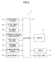
- FIG. 2 is a block diagram showing a configuration of a work state monitoring device 21 according to the present invention.
- the work state monitoring device 21 is installed on the crane 1. Based on a current work state, the work state monitoring device 21 calculates information regarding a prior-warning work state, which is a work state prior to receiving a warning, corresponding to a load factor set lower than the warning load factor and informs the operator of the calculated information.
- a prior-warning work state which is a work state prior to receiving a warning, corresponding to a load factor set lower than the warning load factor
- the work state monitoring device 21 of this embodiment uses working radiuses or actual weights of the crane 1 as the information regarding the work state to be informed to the operator.
- the working radiuses of the crane 1 mean horizontal distances from the rotation center of the boom 7 (i.e., the center of the connection point of the swivel base 3) to the edge of the boom 7.
- the actual weights of the crane 1 mean weights on the end part of the boom 7.
- a main part of the work state monitoring device 21 is a calculator 22 for executing various calculation processes.
- the calculator 22 may be installed inside the cabin 4, for example.
- a work posture detector (a rotating angle detector 23, a jib-tilt angle detector 24, a jib-length detector 25, an outrigger extension length detector 26, a boom length detector 27, a boom angle detector 28, and a cylinder-pressure sensor 29) and an operation unit 30 are connected.
- a monitor 31 On the output side of the calculator 22, a buzzer 32, and a yellow light 33 are connected.
- a work state acquisition section of the present invention is configured with the work posture detector.
- An informer of the present invention is configured with the monitor 31 and the buzzer 32.
- the rotating angle detector 23 is attached to the swivel base 3 and detects rotation angles of the boom 7.
- the jib-tilt angle detector 24 is attached to a jib (not illustrated) and detects tilt angles of the jib (angle in the vertical direction).
- the jib-length detector 25 is attached to the jib and detects lengths of the jib.
- the jib is used to support the work in a working area where the work vehicle cannot perform the work only with the boom 7.
- the jib is mounted beside the boom 7 or is brought to a work place separately, and attached to the top part of the boom 7 when needed.
- the outrigger extension length detector 26 is attached to each outrigger 5 and detects extension lengths of each outrigger 5.
- the boom length detector 27 is attached to the boom 7 and detects lengths of the boom 7.
- the boom angle detector 28 is attached to the boom 7 and detects derricking angles of the boom 7.
- the cylinder-pressure sensor 29 is attached to the boom cylinder 9 and detects pressures of the boom cylinder 9.
- the operation unit 30, the monitor 31, and the buzzer 32 are provided inside the cabin 4 (illustrated in FIG. 1 ).
- the operation unit 30 is manipulated by the operator to input load factors and signals to turn ON/OFF the buzzer 32. Note that the operation unit 30 may be configured such that the operator can also input moment load factors.
- the monitor 31 displays three load factors of the crane 1 and information (working radiuses and actual weights) regarding the work state of the crane 1.
- the three load factors are an arbitrary load factor input by the operator through the operation unit 30, a warning load factor (e.g., 90%) representing a work state close to a work limit, and a limit load factor (e.g., 100%) representing the work limit.
- a warning load factor e.g. 90%
- a limit load factor e.g., 100%
- the buzzer 32 gives a warning to the operator when the actual load factor reaches any of the three load factors.
- the yellow light 33 is installed on the crane 1 and lights when the actual load factor reaches the warning load factor (e.g., 90%).
- FIG. 3 is a view illustrating contents displayed on the monitor 31.
- a load factors indicating section 310 is displayed in a top half portion of a screen 31a of the monitor 31.
- the load factors indicating section 310 has a first load factor indicator 311, a second load factor indicator 312, and a third load factor indicator 313 arranged from left to right.
- the first load factor indicator 311 displays the arbitrary load factor input by the operator through the operation unit 30.
- the second load factor indicator 312 displays the warning load factor (e.g., 90%).
- the third load factor indicator 313 displays the limit load factor (e.g., 100%) to show the work limit.
- the second load factor indicator 312 and the third load factor indicator 313 display the corresponding load factors once the work state monitoring device 21 is powered ON.
- a buzzer states indicating section 320 is displayed above the load factors indicating section 310.
- the buzzer states indicating section 320 has a first buzzer state indicator 321, a second buzzer state indicator 322, and a third buzzer state indicator 323 above the load factor indicators 311 to 313 respectively.
- Each of the buzzer state indicators 321 to 323 displays the ON/OFF state of the buzzer 32.
- a first work state indicating section 330 is displayed below the load factors indicating section 310.
- the first work state indicating section 330 has an actual weight indicator 334, a first working radius indicator 331, a second working radius indicator 332, and a third working radius indicator 333 arranged from left to right.
- the actual weight indicator 334 displays the actual weight (current weight) corresponding to working posture of the work state monitoring device 21 when the device 21 is turned ON.
- the first working radius indicator 331 displays a working radius corresponding to the load factor displayed on the first load factor indicator 311 (i.e., the arbitrary load factor input by the operator) under the current working posture.
- the second working radius indicator 332 displays a working radius corresponding to the load factor displayed on the second load factor indicator 312 (i.e., the warning load factor) under the current working posture.
- the third working radius indicator 333 displays a working radius corresponding to the load factor displayed on the third load factor indicator 313 (i.e., the limit load factor) under the current working posture.
- a second work state indicating section 340 is displayed below the first work state indicating section 330.
- the second work state indicating section 340 has a current working radius indicator 344, a first weight indicator 341, a second weight indicator 342, and a third weight indicator 343 arranged from left to right.
- the current working radius indicator 344 displays a working radius (current working radius) corresponding to the working posture of the work state monitoring device 21 when the device 21 is turned ON.
- the first weight indicator 341 displays an actual weight corresponding to the load factor displayed on the first load factor indicator 311 (the arbitrary load factor input by the operator) under the current working posture.
- the second weight indicator 342 displays an actual weight corresponding to the load factor displayed on the second load factor indicator 312 (the warning load factor) under the current working posture.
- the third weight indicator 343 displays an actual weight corresponding to the load factor displayed on the third load factor indicator 313 (the limit load factor) under the current working posture.
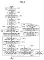
- the process has a working radius displaying process and an actual weight displaying process.
- the working radius displaying process is a process to display the working radiuses corresponding to the load factors.
- the actual weight displaying process is a process to display the actual weights corresponding to the load factors.
- the calculator 22 determines whether the load factor is set or input by the operator through the operation unit 30.
- the load factor is set to be smaller than the warning load factor (90%) in advance. In this embodiment, the load factor is set to be 80%.
- the calculator 22 displays the set load factor on the first load factor indicator 311 of the monitor 31 (see FIG. 3 ).
- the calculator 22 calculates the current actual weight based on the pressure of the boom cylinder 9 detected by the cylinder-pressure sensor 29 and displays the calculated actual weight on the actual weight indicator 334 of the monitor 31.
- the calculator 22 calculates the current working radius based on the derricking angle of the boom 7 detected by the boom angle detector 28, the current boom length of the boom 7 detected by the boom length detector 27, and the actual weight calculated in Step SA3.
- the calculator 22 calculates the current load factor based on the current working radius calculated in the Step SA4 and determines whether the calculated current load factor is greater than the set load factor (i.e., the load factor input by the operator).
- the calculator 22 assigns the current derricking angle as a "derricking angle 2". The calculator 22 then increases the current derricking angle and assigns a "derricking angle 1" virtually.
- the calculator 22 determines whether the current load factor is equal to the set load factor.
- the calculator 22 assigns the current derricking angle as the "derricking angle 1". Further, the calculator 22 decreases the current derricking angle and assigns the "derricking angle 2" virtually.
- the calculator 22 calculates the working radius (virtual working radius) based on the "derricking angle 3" calculated in Step SA12, the boom length of the boom 7 detected by the boom length detector 27, and the current actual weight calculated in Step SA3.
- the calculator 22 calculates the load factor (virtual load factor) based on the working radius calculated in Step SA13 and determines whether the calculated load factor is greater than the set load factor.
- the calculator 22 assigns the "derricking angle 3" calculated in Step SA12 as the "derricking angle 2".
- the calculator 22 re-calculates the "derricking angle 3" based on the newly assigned “derricking angle 2" and calculates the working radius and load factor based on the re-calculated "derricking angle 3". The calculator 22 then determines whether the newly calculated load factor is greater than the set load factor. The calculator 22 continues the above processes until the calculated load factor becomes equal to or smaller than the set load factor.
- the calculator 22 determines whether the calculated load factor is equal to the set load factor.
- the calculator 22 assigns the "derricking angle 3" calculated in Step SA12 as the "derricking angle 1".
- the calculator 22 re-calculates the "derricking angle 3" based on the newly assigned “derricking angle 1" and calculates the working radius and load factor based on the re-calculated "derricking angle 3". The calculator 22 then determines whether the newly calculated load factor is greater than the set load factor. The calculator 22 continues the above processes until the calculated load factor becomes equal to the set load factor.
- the calculator 22 displays the working radius calculated in Step SA13 on the first working radius indicator 331 (see FIG. 3 ) of the monitor 31.
- the calculator 22 displays the working radius calculated in Step SA4 on the first working radius indicator 331 (see FIG. 3 ) of the monitor 31.
- the calculator 22 also calculates the working radius corresponding to the warning load factor (90%) in the same manner as the above Steps SA4 to SA19 and displays the calculated working radius on the second working radius indicator 332 (see FIG. 3 ).
- the calculator 22 displays the rated working radius, which is stored in the calculator 22 in advance, as the working radius corresponding to the limit load factor (100%) on the third working radius indicator 333 (see FIG. 3 ) of the monitor 31.
- the calculator 22 displays the working radiuses corresponding to the load factors (80%, 90%, and 100%) as explained above.
- the work state monitoring device 21 is configured to calculate at least the information regarding the prior-warning work state based on the information regarding the current work state including the current actual weight and to inform the operator of the calculated information.
- the work state monitoring device 21 according to the embodiment can inform the operator of the information regarding the prior-warning work state in advance.
- the work state monitoring device 21 according to the embodiment can allow the operator to perform the work without receiving a warning (i.e., without lighting the yellow light 33).
- the work state monitoring device 21 is configured to use the working radiuses as the information regarding the prior-warning work state to be informed to the operator. With this, the operator can easily recognize the information regarding the work state, thereby enabling of the work without receiving a warning.
- Steps SB1 to SB2 Since the processes in Steps SB1 to SB2 are identical to those in Steps SA1 to SA2, the explanation is omitted.
- the calculator 22 calculates the current working radius based on the values detected by the rotating angle detector 23, jib-tilt angle detector 24, jib length detector 25, outrigger extension length detector 26, boom length detector 27, and boom angle detector 28. The calculator 22 then displays the calculated working radius on the current working radius indicator 344 of the monitor 31.
- the calculator 22 further calculates the rated total weight based on the current working radius calculated in Step SB3 and assigns the rated total weight as a "weight 2".
- the calculator 22 determines whether a good is hooked by the boom 7. This determination is made based on a change amount of the pressure of the boom cylinder 9 detected by the cylinder-pressure sensor 29, a change amount of the derricking angle of the boom 7 detected by the boom angle detector 28, and/or the like.
- the calculator 22 calculates the weight of the good based on the change amounts of the pressure of the boom cylinder 9, the change amount of the derricking angle of the boom 7, and the like. The calculator 22 then assigns the calculated weight of the good as a "weight 1".
- the calculator 22 assigns the weight of the hook 11, which is stored in the calculator 22 in advance, as the "weight 1".
- the calculator 22 calculates the load factor (virtual load factor) based on the "weight 3" calculated in Step SB8 and determines whether the calculated load factor is greater than the set load factor.
- the calculator 22 assigns the "weight 3" as the "weight 2".
- the calculator 22 re-calculates the "weight 3" based on the newly assigned “weight 2" and calculates the load factor based on the re-calculated "weight 3". The calculator 22 then determines whether the newly calculated load factor is greater than the set load factor. The calculator 22 continues the above processes until the calculated load factor becomes equal to or smaller than the set load factor.
- the calculator 22 determines whether the calculated load factor is equal to the set load factor.
- the calculator 22 assigns the "weight 3" calculated in Step SB 8 as the "weight 1".
- the calculator 22 re-calculates the "weight 3" based on the newly assigned “weight 1" and calculates the load factor based on the re-calculated "weight 3". The calculator 22 then determines whether the newly calculated load factor is equal to the set load factor. The calculator 22 continues the above processes until the calculated load factor becomes equal to the set load factor.
- the calculator 22 displays the weight 3 on the first weight indicator 341 (see FIG. 3 ) of the monitor 31 as the actual weight.
- the calculator 22 also calculates the actual weight corresponding to the warning load factor (90%) in the same manner as the above Steps SB3 to SB14 and displays the calculated actual weight on the second weight indicator 342 (see FIG. 3 ).
- the calculator 22 displays the rated total weight, which is stored in the calculator 22 in advance, as the actual weight corresponding to the limit load factor (100%) on the third weight indicator 343 (see FIG. 3 ) of the monitor 31.
- the calculator 22 displays the actual weights corresponding to the load factors (80%, 90%, and 100%) as explained above.
- the work state monitoring device 21 is configured to use the information regarding the current actual weight and the current working radius and to inform the operator of at least the information regarding the prior-warning work state.
- the work state monitoring device 21 can inform the operator of the information regarding the prior-warning work state in advance.
- the work state monitoring device 21 according to the embodiment can allow the operator to perform the work without receiving a warning (i.e., without lighting the yellow light 33).
- the work state monitoring device 21 is configured to use the working radiuses as the information regarding the prior-warning work state to be informed to the operator. With this, the operator can easily recognize the information regarding the prior-warning work state, thereby enabling of the work without receiving a warning.
- the operator may arbitrarily set the timing to turn ON the buzzer 32 with respect to the load factors using the operation unit 30 so as to sound the buzzer 32 when the current load factor reaches a set load factor to turn ON the buzzer 32.
- the work state monitoring device 21 may also sound the buzzer 32 before the current load factor reaches the set load factor to turn ON the buzzer 32.
- the alarm sound made when the current load factor reaches the set load factor and the alarm sound made before the current load factor reaches the set load factor are preferably distinguished.
- the work state monitoring device 21 of the embodiment of the present invention includes the working radius displaying process and the actual weight displaying process.
- the work state monitoring device 21 of the present invention may include only one of the processes.
- the operator inputs a load factor (arbitrary load factor), and the device 21 displays the information regarding the prior-warning work state accordingly.
- the load factor may not be input by the operator but may be stored in the calculator 22 in advance.
- the work state monitoring device 21 of the embodiment uses the boom length detector 27 and the like as the work posture detector.
- the work posture detector may be virtually replaced with the calculator 22 to simulate the information regarding the prior-warning work state.
- the work state monitoring device 21 of the embodiment displays the working radiuses corresponding to the load factors as the information regarding the prior-warning work state.
- the device 21 may display the derricking angles under the working radiuses corresponding to the load factors, instead of the working radiuses.
- the work state monitoring device 21 of the embodiment may automatically stop the crane 1 when the current load factor reaches a load factor that is smaller than the limit load factor (100%).
- the work state monitoring device 21 of the embodiment calculates the working radiuses corresponding to the set load factors by virtually increasing and decreasing the derricking angles. However, the device 21 may calculate the working radiuses by virtually increasing and decreasing the extension amounts of the boom 7. Further, in consideration of the operations of extending and contracting the boom 7 or of rotating the swivel base 3, the device 21 may display the information regarding the prior-warning work state corresponding to the set load factor three-dimensionally.
- the work state monitoring device 21 may use a screen that can display three-dimensional image to display a rotating position (as information regarding the prior-warning work state) corresponding to the set load factor under the current actual weight. Further, the device 21 may display a total rated weight curve on the screen and the working radius corresponding to the set load factor on the total rated weight curve.
- the work state monitoring device 21 is applied to the crane 1, the device 21 may be applied to other work vehicle such as a high lift work vehicle.
- a high lift work vehicle includes a main body of a vehicle (vehicle body), a boom rotatably installed on the vehicle body, and a bucket connected with a top end of the boom.
- the boom and bucket correspond to the working device of the present invention.
- the actual weight of the high lift work vehicle is a weight on the top end of the working device (i.e., a sum of a weight of the bucket, a weight of the operator, and a total weight of tools carried in the bucket).
- the working radius of the high lift work vehicle is a horizontal distance from the rotation center of the boom (i.e., the center of the connection point of boom) to the edge of the bucket.
- the work state monitoring device 21 of the embodiment is configured to detect the actual weight by the cylinder-pressure sensor 29 installed on the boom cylinder 9. However, it should not be limited to the cylinder-pressure sensor 29.
Landscapes
- Engineering & Computer Science (AREA)
- Mechanical Engineering (AREA)
- Jib Cranes (AREA)
- Forklifts And Lifting Vehicles (AREA)
Abstract
Description
- This invention is related to a work state monitoring device that is used by an operator of a work vehicle, such as a crane, to monitor a work state of the vehicle.
- Conventionally, a work state monitoring device has been used for an operator to monitor the work state of a work vehicle such as a crane.
- Some of the conventional work state monitoring devices generate a graph of total rated weights (at 100% load factor) related to working radiuses (for example, the Patent Literature 1). In the work state monitoring device of the
Patent Literature 1, when the current weight is close to or even surpasses the total rated weight, the work is forcibly terminated and the weight is decreased to be within the graph. - In other work state monitoring devices, operators are warned by, for example a yellow light installed on the work vehicle when the current weight is close to the total rated weight, and the operators are warned by a red light when the current weight reaches the total rated weight.
- Patent Literature 1:
Japanese Patent No. 3,136,110 - In some of work sites, the operators are expected not to light the yellow light (i.e., not to be warned by the yellow light). However, the operators of the conventional device can only know the work state (e.g., loads and/or working radiuses) shown by the graph at 100% load factor. Therefore, it is difficult for the operators to perform the work without lighting the yellow light.
- In order to solve the above problem, an object of this invention is, therefore, to provide a work state monitoring device for a work vehicle such that an operator can perform the work without receiving a warning.
- In order to solve the above problem, the inventor of the present invention has invented a work state monitoring device for a work vehicle as described below.
- A work state monitoring device for a work vehicle of the present invention includes a work state acquisition section that acquires information regarding a current work state of the work vehicle, a calculator that calculates at least information regarding a prior-warning work state, which is a work state prior to receiving a warning, corresponding to a load factor set lower than a warning load factor to generate the warning based on the information regarding the current work state acquired by the work state acquisition section, and an informer that informs an operator of the information regarding the prior-warning work state calculated by the calculator.
- When the work vehicle includes a vehicle body and a working device attached to the vehicle body for operating a work, the work state acquisition section may acquire information regarding a current actual weight representing an actual weight on a top end of the working device as the information regarding the current work state. Further, the calculator calculates a working radius representing a horizontal distance from a connection point of the working device with the vehicle body to the top end of the working device based on the acquired information regarding the current actual weight, as the information regarding the prior-warning work state. The informer then informs an operator of the calculated working radius.
- The work state acquisition section may acquire information regarding a current working radius representing a horizontal distance from a connection point of the working device with the vehicle body to a top end of the working device, as the information regarding the current work state. Further, the calculator calculates an actual weight representing an actual weight on the top end of the working device based on the acquired information regarding the current working radius, as the information regarding the prior-warning work state. The informer then informs an operator of the calculated actual weight.
- When the work vehicle includes a vehicle body and a working device derrickably attached to the vehicle body for operating a work, the work state acquisition section acquires information regarding a current actual weight representing an actual weight on a top end of the working device, as the information regarding the current work state. Further, the calculator calculates a derricking angle based on the acquired information regarding the current actual weight, as the information regarding the prior-warning work state. The informer then informs an operator of the calculated derricking angle.
- The work state monitoring device for the work vehicle according to the present invention calculates at least information regarding a prior-warning work state, which is a work state prior to receiving a warning, corresponding to a load factor set lower than the warning work state based on a current work state and informs an operator of the calculated information. Therefore, the work state monitoring device of the present invention can inform the operator of the information regarding the prior-warning work state in advance. As a result, the work state monitoring device of the present invention can allow the operator to perform the work without receiving a warning.
-
- [
FIG. 1] FIG. 1 is a side view illustrating a crane of an embodiment according to a present invention. - [
FIG. 2] FIG. 2 is a block diagram showing a configuration of a work state monitoring device according to the embodiment installed in the crane. - [
FIG. 3] FIG. 3 is a view illustrating contents displayed on a monitor ofFig. 2 . - [
FIG. 4] FIG. 4 is a flowchart showing processes executed by the work state monitoring device of the embodiment for displaying working radiuses. - [
FIG. 5] FIG. 5 is a flowchart showing processes executed by the work state monitoring device of the embodiment for displaying actual weights. - Hereinafter, an embodiment of the present invention will be explained with reference to the drawings.
-
FIG. 1 is a side view illustrating acrane 1 of an embodiment according to a present invention. An overall structure of thecrane 1 will be explained first. Thecrane 1 includes acarrier 2, which is a main body of a vehicle (vehicle body) capable of traveling, aswivel base 3 attached on top of thecarrier 2 to be horizontally rotatable, and acabin 4 provided on theswivel base 3. - On each of the front side and back side of the
carrier 2, a pair of left and right outriggers 5 (only one of them are illustrated) are provided. On theswivel base 3, abracket 6 is fixed. Thebracket 6 has aboom 7. Theboom 7 corresponds to a working device of the present invention. - The
boom 7 is connected to thebracket 6 at the base part of theboom 7 with asupport shaft 8 and is risen up and fallen down around thesupport shaft 8. Aboom cylinder 9 is interposed between thebracket 6 and theboom 7. Theboom 7 can rise up and fall down as theboom cylinder 9 extends and retracts. - The
boom 7 has abase boom section 7a, anintermediate boom section 7b, and atop boom section 7c. Thetop boom section 7c is accommodated in theintermediate boom section 7b, and theintermediate boom section 7b is accommodated in thetop boom section 7c. Each of theboom sections 7a-7c is connected via a telescopic cylinder (not illustrated) and are extended and retracted as the telescopic cylinder extends and retracts. - A
boom head 7d of thetop boom section 7c is provided with a sheave (not illustrated). Thebracket 6 is provided with a winch (not illustrated). The winch suspends a wire W, and the wire W is wounded around the sheave. The wire W suspends ahook block 10 to which ahook 11 is attached. Thehook 11 can hook goods (not illustrated) with a wire rope (not illustrated). - An operation unit (not illustrated) is installed inside the
cabin 4. The operation unit is manipulated by an operator to rotate theswivel base 3, to rise up and fall down theboom 7, to reel in and out the wire W with the winch, to extend and contracts theoutriggers 5, to start and stop an engine, and the like. -
FIG. 2 is a block diagram showing a configuration of a workstate monitoring device 21 according to the present invention. The workstate monitoring device 21 is installed on thecrane 1. Based on a current work state, the workstate monitoring device 21 calculates information regarding a prior-warning work state, which is a work state prior to receiving a warning, corresponding to a load factor set lower than the warning load factor and informs the operator of the calculated information. - The work
state monitoring device 21 of this embodiment uses working radiuses or actual weights of thecrane 1 as the information regarding the work state to be informed to the operator. Here, the working radiuses of thecrane 1 mean horizontal distances from the rotation center of the boom 7 (i.e., the center of the connection point of the swivel base 3) to the edge of theboom 7. The actual weights of thecrane 1 mean weights on the end part of theboom 7. - A main part of the work
state monitoring device 21 is acalculator 22 for executing various calculation processes. Thecalculator 22 may be installed inside thecabin 4, for example. - On the input side of the
calculator 22, a work posture detector (arotating angle detector 23, a jib-tilt angle detector 24, a jib-length detector 25, an outriggerextension length detector 26, aboom length detector 27, aboom angle detector 28, and a cylinder-pressure sensor 29) and anoperation unit 30 are connected. On the output side of thecalculator 22, amonitor 31, abuzzer 32, and ayellow light 33 are connected. - In the work
state monitoring device 21, a work state acquisition section of the present invention is configured with the work posture detector. An informer of the present invention is configured with themonitor 31 and thebuzzer 32. - The
rotating angle detector 23 is attached to theswivel base 3 and detects rotation angles of theboom 7. The jib-tilt angle detector 24 is attached to a jib (not illustrated) and detects tilt angles of the jib (angle in the vertical direction). The jib-length detector 25 is attached to the jib and detects lengths of the jib. - The jib is used to support the work in a working area where the work vehicle cannot perform the work only with the
boom 7. The jib is mounted beside theboom 7 or is brought to a work place separately, and attached to the top part of theboom 7 when needed. - The outrigger
extension length detector 26 is attached to eachoutrigger 5 and detects extension lengths of eachoutrigger 5. Theboom length detector 27 is attached to theboom 7 and detects lengths of theboom 7. - The
boom angle detector 28 is attached to theboom 7 and detects derricking angles of theboom 7. The cylinder-pressure sensor 29 is attached to theboom cylinder 9 and detects pressures of theboom cylinder 9. - The
operation unit 30, themonitor 31, and thebuzzer 32 are provided inside the cabin 4 (illustrated inFIG. 1 ). Theoperation unit 30 is manipulated by the operator to input load factors and signals to turn ON/OFF thebuzzer 32. Note that theoperation unit 30 may be configured such that the operator can also input moment load factors. - The
monitor 31 displays three load factors of thecrane 1 and information (working radiuses and actual weights) regarding the work state of thecrane 1. - The three load factors are an arbitrary load factor input by the operator through the
operation unit 30, a warning load factor (e.g., 90%) representing a work state close to a work limit, and a limit load factor (e.g., 100%) representing the work limit. Note that the load factors displayed on themonitor 31 should not be limited to the above values and may be set arbitrarily. - The
buzzer 32 gives a warning to the operator when the actual load factor reaches any of the three load factors. Theyellow light 33 is installed on thecrane 1 and lights when the actual load factor reaches the warning load factor (e.g., 90%). -
FIG. 3 is a view illustrating contents displayed on themonitor 31. A loadfactors indicating section 310 is displayed in a top half portion of ascreen 31a of themonitor 31. The loadfactors indicating section 310 has a firstload factor indicator 311, a secondload factor indicator 312, and a thirdload factor indicator 313 arranged from left to right. - The first
load factor indicator 311 displays the arbitrary load factor input by the operator through theoperation unit 30. The secondload factor indicator 312 displays the warning load factor (e.g., 90%). The thirdload factor indicator 313 displays the limit load factor (e.g., 100%) to show the work limit. - The second
load factor indicator 312 and the thirdload factor indicator 313 display the corresponding load factors once the workstate monitoring device 21 is powered ON. - A buzzer states indicating
section 320 is displayed above the loadfactors indicating section 310. The buzzer states indicatingsection 320 has a firstbuzzer state indicator 321, a secondbuzzer state indicator 322, and a thirdbuzzer state indicator 323 above theload factor indicators 311 to 313 respectively. Each of thebuzzer state indicators 321 to 323 displays the ON/OFF state of thebuzzer 32. - A first work
state indicating section 330 is displayed below the loadfactors indicating section 310. The first workstate indicating section 330 has anactual weight indicator 334, a firstworking radius indicator 331, a secondworking radius indicator 332, and a thirdworking radius indicator 333 arranged from left to right. - The
actual weight indicator 334 displays the actual weight (current weight) corresponding to working posture of the workstate monitoring device 21 when thedevice 21 is turned ON. - The first
working radius indicator 331 displays a working radius corresponding to the load factor displayed on the first load factor indicator 311 (i.e., the arbitrary load factor input by the operator) under the current working posture. - The second
working radius indicator 332 displays a working radius corresponding to the load factor displayed on the second load factor indicator 312 (i.e., the warning load factor) under the current working posture. - The third
working radius indicator 333 displays a working radius corresponding to the load factor displayed on the third load factor indicator 313 (i.e., the limit load factor) under the current working posture. - A second work
state indicating section 340 is displayed below the first workstate indicating section 330. The second workstate indicating section 340 has a currentworking radius indicator 344, afirst weight indicator 341, asecond weight indicator 342, and athird weight indicator 343 arranged from left to right. - The current
working radius indicator 344 displays a working radius (current working radius) corresponding to the working posture of the workstate monitoring device 21 when thedevice 21 is turned ON. - The
first weight indicator 341 displays an actual weight corresponding to the load factor displayed on the first load factor indicator 311 (the arbitrary load factor input by the operator) under the current working posture. - The
second weight indicator 342 displays an actual weight corresponding to the load factor displayed on the second load factor indicator 312 (the warning load factor) under the current working posture. - The
third weight indicator 343 displays an actual weight corresponding to the load factor displayed on the third load factor indicator 313 (the limit load factor) under the current working posture. - Next, a process executed by the work
state monitoring device 21 to display the information regarding the work state will be explained. The process has a working radius displaying process and an actual weight displaying process. The working radius displaying process is a process to display the working radiuses corresponding to the load factors. The actual weight displaying process is a process to display the actual weights corresponding to the load factors. Each of the processes will be explained below. - First, the working radius displaying process will be explained with reference to
FIG. 4 flowchart. - The
calculator 22 determines whether the load factor is set or input by the operator through theoperation unit 30. The load factor is set to be smaller than the warning load factor (90%) in advance. In this embodiment, the load factor is set to be 80%. - When it is determined that the load factor is input by the operator through the operation unit 30 (i.e., when the determination result in Step SA1 is YES), the
calculator 22 displays the set load factor on the firstload factor indicator 311 of the monitor 31 (seeFIG. 3 ). - The
calculator 22 calculates the current actual weight based on the pressure of theboom cylinder 9 detected by the cylinder-pressure sensor 29 and displays the calculated actual weight on theactual weight indicator 334 of themonitor 31. - The
calculator 22 calculates the current working radius based on the derricking angle of theboom 7 detected by theboom angle detector 28, the current boom length of theboom 7 detected by theboom length detector 27, and the actual weight calculated in Step SA3. - The
calculator 22 calculates the current load factor based on the current working radius calculated in the Step SA4 and determines whether the calculated current load factor is greater than the set load factor (i.e., the load factor input by the operator). - When it is determined that the current load factor is greater than the set load factor (i.e., when the determination result in Step SA6 is YES), the
calculator 22 assigns the current derricking angle as a "derricking angle 2". Thecalculator 22 then increases the current derricking angle and assigns a "derricking angle 1" virtually. - When it is determined that the current load factor is not greater than the set load factor (i.e., when the determination result in Step SA6 is NO), the
calculator 22 determines whether the current load factor is equal to the set load factor. - When it is determined that the current load factor is not equal to the set load factor, in other words, when it is determined that the current load factor is smaller than the set load factor (i.e., when the determination result in Step SA9 is NO); the
calculator 22 assigns the current derricking angle as the "derricking angle 1". Further, thecalculator 22 decreases the current derricking angle and assigns the "derricking angle 2" virtually. - Based on the "
derricking angle 1" assigned in Step SA8 or Step SA10 and the "derricking angle 2" assigned in Step SA7 or Step SA11, thecalculator 22 calculates a derricking angle 3 (virtual derricking angle) in accordance with the following equation:
- The
calculator 22 calculates the working radius (virtual working radius) based on the "derricking angle 3" calculated in Step SA12, the boom length of theboom 7 detected by theboom length detector 27, and the current actual weight calculated in Step SA3. - The
calculator 22 calculates the load factor (virtual load factor) based on the working radius calculated in Step SA13 and determines whether the calculated load factor is greater than the set load factor. - When it is determined that the calculated load factor is greater than the set load factor (i.e., when the determination result in Step SA15 is YES), the
calculator 22 assigns the "derricking angle 3" calculated in Step SA12 as the "derricking angle 2". - The
calculator 22 re-calculates the "derricking angle 3" based on the newly assigned "derricking angle 2" and calculates the working radius and load factor based on the re-calculated "derricking angle 3". Thecalculator 22 then determines whether the newly calculated load factor is greater than the set load factor. Thecalculator 22 continues the above processes until the calculated load factor becomes equal to or smaller than the set load factor. - When it is determined that the calculated load factor is equal to or smaller than the set load factor (i.e., when the determination result in Step SA15 is NO), the
calculator 22 determines whether the calculated load factor is equal to the set load factor. - When it is determined that the calculated load factor is not equal to the set load factor (i.e., when the determination result in Step SA17 is NO), the
calculator 22 assigns the "derricking angle 3" calculated in Step SA12 as the "derricking angle 1". - The
calculator 22 re-calculates the "derricking angle 3" based on the newly assigned "derricking angle 1" and calculates the working radius and load factor based on the re-calculated "derricking angle 3". Thecalculator 22 then determines whether the newly calculated load factor is greater than the set load factor. Thecalculator 22 continues the above processes until the calculated load factor becomes equal to the set load factor. - When it is determined that the calculated load factor is equal to the set load factor (i.e., when the determination result in Step SA17 is YES), the
calculator 22 displays the working radius calculated in Step SA13 on the first working radius indicator 331 (seeFIG. 3 ) of themonitor 31. - When it is determined that the current load factor is equal to the set load factor in Step SA9 (i.e., when the determination result in Step SA9 is YES), the
calculator 22 displays the working radius calculated in Step SA4 on the first working radius indicator 331 (seeFIG. 3 ) of themonitor 31. - Further, the
calculator 22 also calculates the working radius corresponding to the warning load factor (90%) in the same manner as the above Steps SA4 to SA19 and displays the calculated working radius on the second working radius indicator 332 (seeFIG. 3 ). - Note that the
calculator 22 displays the rated working radius, which is stored in thecalculator 22 in advance, as the working radius corresponding to the limit load factor (100%) on the third working radius indicator 333 (seeFIG. 3 ) of themonitor 31. - The
calculator 22 displays the working radiuses corresponding to the load factors (80%, 90%, and 100%) as explained above. - As mentioned above, the work
state monitoring device 21 according to this embodiment is configured to calculate at least the information regarding the prior-warning work state based on the information regarding the current work state including the current actual weight and to inform the operator of the calculated information. With this, the workstate monitoring device 21 according to the embodiment can inform the operator of the information regarding the prior-warning work state in advance. As a result, the workstate monitoring device 21 according to the embodiment can allow the operator to perform the work without receiving a warning (i.e., without lighting the yellow light 33). - Further, the work
state monitoring device 21 according to the embodiment is configured to use the working radiuses as the information regarding the prior-warning work state to be informed to the operator. With this, the operator can easily recognize the information regarding the work state, thereby enabling of the work without receiving a warning. - Next, the weight displaying process will be explained with reference to
FIG. 5 flowchart. - Since the processes in Steps SB1 to SB2 are identical to those in Steps SA1 to SA2, the explanation is omitted.
- The
calculator 22 calculates the current working radius based on the values detected by therotating angle detector 23, jib-tilt angle detector 24,jib length detector 25, outriggerextension length detector 26,boom length detector 27, andboom angle detector 28. Thecalculator 22 then displays the calculated working radius on the currentworking radius indicator 344 of themonitor 31. - The
calculator 22 further calculates the rated total weight based on the current working radius calculated in Step SB3 and assigns the rated total weight as a "weight 2". - The
calculator 22 determines whether a good is hooked by theboom 7. This determination is made based on a change amount of the pressure of theboom cylinder 9 detected by the cylinder-pressure sensor 29, a change amount of the derricking angle of theboom 7 detected by theboom angle detector 28, and/or the like. - When it is determined that a good is hooked by the boom 7 (i.e., when the determination result in Step SB5 is YES), the
calculator 22 calculates the weight of the good based on the change amounts of the pressure of theboom cylinder 9, the change amount of the derricking angle of theboom 7, and the like. Thecalculator 22 then assigns the calculated weight of the good as a "weight 1". - When it is determined that no good is hooked by the boom 7 (i.e., when the determination result in Step SB5 is NO), the
calculator 22 assigns the weight of thehook 11, which is stored in thecalculator 22 in advance, as the "weight 1". - Based on the "
weight 1" assigned in Step SB6 or Step SB7 and the "weight 2" assigned in Step SB4, thecalculator 22 calculates aweight 3 in accordance with the following equation:
- The
calculator 22 calculates the load factor (virtual load factor) based on the "weight 3" calculated in Step SB8 and determines whether the calculated load factor is greater than the set load factor. - When it is determined that the calculated load factor is greater than the set load factor (i.e., when the determination result in
Step SB 10 is YES), thecalculator 22 assigns the "weight 3" as the "weight 2". - The
calculator 22 re-calculates the "weight 3" based on the newly assigned "weight 2" and calculates the load factor based on the re-calculated "weight 3". Thecalculator 22 then determines whether the newly calculated load factor is greater than the set load factor. Thecalculator 22 continues the above processes until the calculated load factor becomes equal to or smaller than the set load factor. - When it is determined that the calculated load factor is smaller than the set load factor (i.e., when the determination result in Step SB10 is NO), the
calculator 22 determines whether the calculated load factor is equal to the set load factor. - When it is determined that the calculated load factor is not equal to the set load factor (i.e., when the determination result in Step SB 12 is NO), the
calculator 22 assigns the "weight 3" calculated inStep SB 8 as the "weight 1". - The
calculator 22 re-calculates the "weight 3" based on the newly assigned "weight 1" and calculates the load factor based on the re-calculated "weight 3". Thecalculator 22 then determines whether the newly calculated load factor is equal to the set load factor. Thecalculator 22 continues the above processes until the calculated load factor becomes equal to the set load factor. - When it is determined that the calculated load factor is equal to the set load factor (i.e., when the determination result in Step SB12 is YES), the
calculator 22 displays theweight 3 on the first weight indicator 341 (seeFIG. 3 ) of themonitor 31 as the actual weight. - Further, the
calculator 22 also calculates the actual weight corresponding to the warning load factor (90%) in the same manner as the above Steps SB3 to SB14 and displays the calculated actual weight on the second weight indicator 342 (seeFIG. 3 ). - Note that the
calculator 22 displays the rated total weight, which is stored in thecalculator 22 in advance, as the actual weight corresponding to the limit load factor (100%) on the third weight indicator 343 (seeFIG. 3 ) of themonitor 31. - The
calculator 22 displays the actual weights corresponding to the load factors (80%, 90%, and 100%) as explained above. - As explained above, the work
state monitoring device 21 according to this embodiment is configured to use the information regarding the current actual weight and the current working radius and to inform the operator of at least the information regarding the prior-warning work state. - Therefore, the work
state monitoring device 21 can inform the operator of the information regarding the prior-warning work state in advance. As a result, the workstate monitoring device 21 according to the embodiment can allow the operator to perform the work without receiving a warning (i.e., without lighting the yellow light 33). - Further, the work
state monitoring device 21 according to the embodiment is configured to use the working radiuses as the information regarding the prior-warning work state to be informed to the operator. With this, the operator can easily recognize the information regarding the prior-warning work state, thereby enabling of the work without receiving a warning. - Note that the operator may arbitrarily set the timing to turn ON the
buzzer 32 with respect to the load factors using theoperation unit 30 so as to sound thebuzzer 32 when the current load factor reaches a set load factor to turn ON thebuzzer 32. - Note that the work
state monitoring device 21 may also sound thebuzzer 32 before the current load factor reaches the set load factor to turn ON thebuzzer 32. In this case, the alarm sound made when the current load factor reaches the set load factor and the alarm sound made before the current load factor reaches the set load factor are preferably distinguished. - Although the present invention has been described in terms of exemplary embodiments, it is not limited thereto. It should be appreciated that variations or modifications may be made in the embodiments without departing from the scope of the present invention as defined by the claims.
- In the above explanation, the work
state monitoring device 21 of the embodiment of the present invention includes the working radius displaying process and the actual weight displaying process. However, the workstate monitoring device 21 of the present invention may include only one of the processes. - In the work
state monitoring device 21 of the embodiment, the operator inputs a load factor (arbitrary load factor), and thedevice 21 displays the information regarding the prior-warning work state accordingly. However, the load factor may not be input by the operator but may be stored in thecalculator 22 in advance. - The work
state monitoring device 21 of the embodiment uses theboom length detector 27 and the like as the work posture detector. However, the work posture detector may be virtually replaced with thecalculator 22 to simulate the information regarding the prior-warning work state. - The work
state monitoring device 21 of the embodiment displays the working radiuses corresponding to the load factors as the information regarding the prior-warning work state. However, thedevice 21 may display the derricking angles under the working radiuses corresponding to the load factors, instead of the working radiuses. - The work
state monitoring device 21 of the embodiment may automatically stop thecrane 1 when the current load factor reaches a load factor that is smaller than the limit load factor (100%). - The work
state monitoring device 21 of the embodiment calculates the working radiuses corresponding to the set load factors by virtually increasing and decreasing the derricking angles. However, thedevice 21 may calculate the working radiuses by virtually increasing and decreasing the extension amounts of theboom 7. Further, in consideration of the operations of extending and contracting theboom 7 or of rotating theswivel base 3, thedevice 21 may display the information regarding the prior-warning work state corresponding to the set load factor three-dimensionally. - For example, in consideration of rotating the
swivel base 3, the workstate monitoring device 21 may use a screen that can display three-dimensional image to display a rotating position (as information regarding the prior-warning work state) corresponding to the set load factor under the current actual weight. Further, thedevice 21 may display a total rated weight curve on the screen and the working radius corresponding to the set load factor on the total rated weight curve. - Although the work
state monitoring device 21 according to the embodiment is applied to thecrane 1, thedevice 21 may be applied to other work vehicle such as a high lift work vehicle. - Although not illustrated, a high lift work vehicle includes a main body of a vehicle (vehicle body), a boom rotatably installed on the vehicle body, and a bucket connected with a top end of the boom. In this case, the boom and bucket correspond to the working device of the present invention.
- The actual weight of the high lift work vehicle is a weight on the top end of the working device (i.e., a sum of a weight of the bucket, a weight of the operator, and a total weight of tools carried in the bucket). The working radius of the high lift work vehicle is a horizontal distance from the rotation center of the boom (i.e., the center of the connection point of boom) to the edge of the bucket.
- The work
state monitoring device 21 of the embodiment is configured to detect the actual weight by the cylinder-pressure sensor 29 installed on theboom cylinder 9. However, it should not be limited to the cylinder-pressure sensor 29. - The present application is based on and claims priority from
Japanese Patent Application No. 2013-076997, filed on April 2, 2013
Claims (4)
- A work state monitoring device for a work vehicle, comprising:a work state acquisition section that acquires information regarding a current work state of the work vehicle;a calculator that calculates at least information regarding a prior-warning work state, which is a work state prior to receiving a warning, corresponding to a load factor set lower than a warning load factor to generate the warning based on the information regarding the current work state acquired by the work state acquisition section; andan informer that informs an operator of the information regarding the prior-warning work state calculated by the calculator.
- The device as claimed in claim 1, wherein the work vehicle includes a vehicle body and a working device attached to the vehicle body for operating a work,
as the information regarding the current work state, the work state acquisition section acquires information regarding a current actual weight representing an actual weight on a top end of the working device,
as the information regarding the prior-warning work state, the calculator calculates a working radius representing a horizontal distance from a connection point of the working device with the vehicle body to the top end of the working device based on the acquired information regarding the current actual weight, and
the informer informs an operator of the calculated working radius. - The device as claimed in claim 1, wherein the work vehicle includes a vehicle body and a working device attached to the vehicle body for operating a work,
as the information regarding the current work state, the work state acquisition section acquires information regarding a current working radius representing a horizontal distance from a connection point of the working device with the vehicle body to a top end of the working device,
as the information regarding the prior-warning work state, the calculator calculates an actual weight representing an actual weight on the top end of the working device based on the acquired information regarding the current working radius, and
the informer informs an operator of the calculated actual weight. - The device as claimed in claim 1, wherein the work vehicle includes a vehicle body and a working device derrickably attached to the vehicle body for operating a work,
as the information regarding the current work state, the work state acquisition section acquires information regarding a current actual weight representing an actual weight on a top end of the working device,
as the information regarding the prior-warning work state, the calculator calculates a derricking angle based on the acquired information regarding the current actual weight, and
the informer informs an operator of the calculated derricking angle.
Applications Claiming Priority (2)
| Application Number | Priority Date | Filing Date | Title |
|---|---|---|---|
| JP2013076997A JP6147062B2 (en) | 2013-04-02 | 2013-04-02 | Work condition check device for work equipment |
| PCT/JP2014/057768 WO2014162894A1 (en) | 2013-04-02 | 2014-03-20 | Device for checking working state of work machine |
Publications (3)
| Publication Number | Publication Date |
|---|---|
| EP2982635A1 true EP2982635A1 (en) | 2016-02-10 |
| EP2982635A4 EP2982635A4 (en) | 2017-02-15 |
| EP2982635B1 EP2982635B1 (en) | 2019-11-27 |
Family
ID=51658194
Family Applications (1)
| Application Number | Title | Priority Date | Filing Date |
|---|---|---|---|
| EP14779033.1A Active EP2982635B1 (en) | 2013-04-02 | 2014-03-20 | Device for checking working state of work machine |
Country Status (5)
| Country | Link |
|---|---|
| US (1) | US9783397B2 (en) |
| EP (1) | EP2982635B1 (en) |
| JP (1) | JP6147062B2 (en) |
| CN (1) | CN105102367B (en) |
| WO (1) | WO2014162894A1 (en) |
Cited By (2)
| Publication number | Priority date | Publication date | Assignee | Title |
|---|---|---|---|---|
| WO2018068071A1 (en) * | 2016-10-14 | 2018-04-19 | Palfinger Europe Gmbh | Method for determining a load, controller for a hydraulic lifting device for carrying out a method of this type |
| US12448256B2 (en) | 2022-05-13 | 2025-10-21 | Palfinger Ag | Method for moving a lifting device |
Families Citing this family (15)
| Publication number | Priority date | Publication date | Assignee | Title |
|---|---|---|---|---|
| KR102433942B1 (en) * | 2014-08-19 | 2022-08-19 | 크라운 이큅먼트 코포레이션 | De-centralized operational indicator system for a materials handling vehicle |
| CN104495658B (en) * | 2014-12-31 | 2017-03-15 | 中联重科股份有限公司 | Debugging method, device and system for moment limiter of crane |
| DE102015202734A1 (en) * | 2015-02-16 | 2016-08-18 | Terex Cranes Germany Gmbh | Crane and method for influencing a deformation of a boom system of such a crane |
| CN105819338B (en) * | 2016-04-25 | 2018-01-16 | 乐清市天逸电器有限公司 | Driving handle and its method for measuring weight for crane |
| CN106044593B (en) * | 2016-05-27 | 2018-02-13 | 江汉大学 | Tower crane state monitoring method and device |
| CN106081909A (en) * | 2016-08-09 | 2016-11-09 | 国网河南省电力公司郑州供电公司 | Monitoring lifting bearing in real time |
| US11142438B2 (en) * | 2017-08-28 | 2021-10-12 | Manitowoc Crane Companies, Llc | Graphical working range diagrams for displaying allowable and projected loads |
| CN107720554B (en) * | 2017-11-13 | 2019-05-14 | 长沙海川自动化设备有限公司 | Face upward jib crane and its monitoring method, monitoring device and storage medium |
| JP7091729B2 (en) * | 2018-03-09 | 2022-06-28 | 株式会社タダノ | Work vehicle equipped with a remote control terminal and a remote control terminal |
| CN108862040B (en) * | 2018-07-19 | 2019-11-01 | 湖南中联重科智能技术有限公司 | Determine the method and device of craning weight of same |
| JP7151532B2 (en) * | 2019-02-14 | 2022-10-12 | 株式会社タダノ | Crane and crane path generation system |
| US12221327B2 (en) | 2019-10-17 | 2025-02-11 | Terex Australia Pty Ltd | Mobile crane operation control |
| WO2021127058A1 (en) * | 2019-12-16 | 2021-06-24 | Manitowoc Crane Companies, Llc | System and method for monitoring crane and crane having the same |
| JP7323070B2 (en) * | 2020-06-03 | 2023-08-08 | 株式会社タダノ | Ground-breaking control device and crane |
| JP2024060135A (en) * | 2022-10-19 | 2024-05-02 | ヤンマーホールディングス株式会社 | Work Machine |
Family Cites Families (24)
| Publication number | Priority date | Publication date | Assignee | Title |
|---|---|---|---|---|
| US3819922A (en) * | 1973-05-02 | 1974-06-25 | Forney Eng Co | Crane load and radius indicating system |
| JPH085623B2 (en) * | 1989-09-27 | 1996-01-24 | 株式会社神戸製鋼所 | Crane safety equipment |
| JP2564060B2 (en) * | 1991-10-24 | 1996-12-18 | 株式会社神戸製鋼所 | Safety equipment for construction machinery |
| JP3180996B2 (en) * | 1993-09-10 | 2001-07-03 | 株式会社小松製作所 | Crane movable range display device |
| JP3136110B2 (en) | 1996-04-09 | 2001-02-19 | 日立建機株式会社 | Crane specification display |
| JP3852994B2 (en) * | 1996-11-27 | 2006-12-06 | 株式会社タダノ | Work status display device for work equipment |
| JP2000034093A (en) * | 1998-07-21 | 2000-02-02 | Kobe Steel Ltd | Slewing type working machinery and its safety working area and setting method of rated load |
| JP3197876B2 (en) * | 1999-02-02 | 2001-08-13 | 株式会社タダノ | Boom type work machine display |
| JP4320931B2 (en) * | 2000-03-27 | 2009-08-26 | コベルコクレーン株式会社 | Crane overload prevention method and overload prevention device |
| JP2002241083A (en) * | 2001-02-13 | 2002-08-28 | Hitachi Constr Mach Co Ltd | Safety device for working machine with boom |
| KR20030003015A (en) * | 2001-06-28 | 2003-01-09 | 가부시키가이샤 고마쓰 세이사쿠쇼 | Excavator |
| JP2004001987A (en) * | 2002-03-25 | 2004-01-08 | Hitachi Constr Mach Co Ltd | Operation support device |
| JP2003300690A (en) | 2002-04-11 | 2003-10-21 | Hitachi Constr Mach Co Ltd | Display device of construction machine |
| JP2005001847A (en) * | 2003-06-13 | 2005-01-06 | Hitachi Constr Mach Co Ltd | Display device of working machine |
| JP5169087B2 (en) * | 2006-09-14 | 2013-03-27 | コベルコクレーン株式会社 | Mobile crane safety device |
| DE102009041661A1 (en) * | 2009-09-16 | 2011-03-24 | Liebherr-Werk Nenzing Gmbh, Nenzing | System for the automatic detection of load cycles of a machine for handling loads |
| US8768581B2 (en) * | 2010-05-24 | 2014-07-01 | Hitachi Construction Machinery Co., Ltd. | Work machine safety device |
| CN102607656B (en) * | 2011-01-14 | 2015-12-16 | 株式会社多田野 | Crane fuel consumption display device |
| JP5876679B2 (en) | 2011-07-08 | 2016-03-02 | 株式会社タダノ | Performance line display device |
| JP5204877B2 (en) * | 2011-08-04 | 2013-06-05 | 東海旅客鉄道株式会社 | vehicle |
| JP5723246B2 (en) * | 2011-09-06 | 2015-05-27 | 日立住友重機械建機クレーン株式会社 | Safety equipment for construction machinery |
| KR20140116386A (en) * | 2011-12-30 | 2014-10-02 | 내셔널 오일웰 바르코 엘.피. | Deep water knuckle boom crane |
| JP5889688B2 (en) * | 2012-03-26 | 2016-03-22 | 株式会社タダノ | Work machine |
| JP6121670B2 (en) * | 2012-09-05 | 2017-04-26 | 株式会社タダノ | Work plan confirmation device |
-
2013
- 2013-04-02 JP JP2013076997A patent/JP6147062B2/en active Active
-
2014
- 2014-03-20 US US14/781,286 patent/US9783397B2/en active Active
- 2014-03-20 EP EP14779033.1A patent/EP2982635B1/en active Active
- 2014-03-20 CN CN201480019450.3A patent/CN105102367B/en active Active
- 2014-03-20 WO PCT/JP2014/057768 patent/WO2014162894A1/en not_active Ceased
Cited By (4)
| Publication number | Priority date | Publication date | Assignee | Title |
|---|---|---|---|---|
| WO2018068071A1 (en) * | 2016-10-14 | 2018-04-19 | Palfinger Europe Gmbh | Method for determining a load, controller for a hydraulic lifting device for carrying out a method of this type |
| AU2017342185B2 (en) * | 2016-10-14 | 2020-03-12 | Palfinger Ag | Method for determining a load, controller for a hydraulic lifting device for carrying out a method of this type |
| US12202711B2 (en) | 2016-10-14 | 2025-01-21 | Palfinger Ag | Method for determining a load, controller for a hydraulic lifting device for carrying out a method of this type |
| US12448256B2 (en) | 2022-05-13 | 2025-10-21 | Palfinger Ag | Method for moving a lifting device |
Also Published As
| Publication number | Publication date |
|---|---|
| US9783397B2 (en) | 2017-10-10 |
| WO2014162894A1 (en) | 2014-10-09 |
| JP2014201383A (en) | 2014-10-27 |
| CN105102367A (en) | 2015-11-25 |
| US20160318739A1 (en) | 2016-11-03 |
| JP6147062B2 (en) | 2017-06-14 |
| EP2982635A4 (en) | 2017-02-15 |
| EP2982635B1 (en) | 2019-11-27 |
| CN105102367B (en) | 2017-08-15 |
Similar Documents
| Publication | Publication Date | Title |
|---|---|---|
| EP2982635B1 (en) | Device for checking working state of work machine | |
| CN106715317B (en) | Method and device for operating a mobile crane and mobile crane | |
| JP6017782B2 (en) | Information system for height information of objects around suspended loads | |
| EP0857687A1 (en) | Device for indicating movable range of mobile crane vehicle | |
| EP4036044B1 (en) | Crane information display system | |
| JP2011102167A (en) | Hanging load position monitoring system for crane, and hanging tool | |
| EP3498656A1 (en) | Electric winch device | |
| EP4067285A1 (en) | Monitoring device for winch drum | |
| US20150291399A1 (en) | Slow stopping apparatus for working machine | |
| JP2014174019A (en) | Device and method to measure gravity center of suspended load | |
| CN104591050A (en) | Overhead working truck tipping prevention control method | |
| US20210269285A1 (en) | Crane with an anti-collision device and method for installing such an anti-collision device | |
| EP3925919A1 (en) | Lifting control device and mobile crane | |
| JP6101446B2 (en) | Heavy machine work situation identification system and heavy machine work situation identification method | |
| JP2010228900A (en) | Load calculating device for crane and crane | |
| JP7546598B2 (en) | SYSTEM FOR USE ON A LIFTING MACHINE, SYSTEM FOR USE ON A LOAD TRANSFER MACHINE, AND SYSTEM FOR REPORTING BOOM POSITION INFORMATION | |
| JP2014227281A (en) | Display system for work machine | |
| EP3925920A1 (en) | Dynamic-lift-off determination device, dynamic-lift-off control device, mobile crane, and dynamic-lift-off determination method | |
| JPH0249276Y2 (en) | ||
| JP6121700B2 (en) | Work confirmation device | |
| JP6881096B2 (en) | Mobile crane | |
| JPH11139760A (en) | Load detector device of hoist cargo for mobile crane | |
| CN103130100B (en) | Stationary crane hangs row of horizontal control monitor unit | |
| JP7618087B1 (en) | Mobile crane boom working range determination system | |
| RU2810831C2 (en) | Improved boom with two or more hooks |
Legal Events
| Date | Code | Title | Description |
|---|---|---|---|
| PUAI | Public reference made under article 153(3) epc to a published international application that has entered the european phase |
Free format text: ORIGINAL CODE: 0009012 |
|
| 17P | Request for examination filed |
Effective date: 20151029 |
|
| AK | Designated contracting states |
Kind code of ref document: A1 Designated state(s): AL AT BE BG CH CY CZ DE DK EE ES FI FR GB GR HR HU IE IS IT LI LT LU LV MC MK MT NL NO PL PT RO RS SE SI SK SM TR |
|
| AX | Request for extension of the european patent |
Extension state: BA ME |
|
| DAX | Request for extension of the european patent (deleted) | ||
| A4 | Supplementary search report drawn up and despatched |
Effective date: 20170117 |
|
| RIC1 | Information provided on ipc code assigned before grant |
Ipc: B66C 13/16 20060101ALI20170111BHEP Ipc: B66C 23/42 20060101ALI20170111BHEP Ipc: B66C 23/90 20060101AFI20170111BHEP Ipc: B66C 15/06 20060101ALI20170111BHEP |
|
| STAA | Information on the status of an ep patent application or granted ep patent |
Free format text: STATUS: EXAMINATION IS IN PROGRESS |
|
| 17Q | First examination report despatched |
Effective date: 20181016 |
|
| REG | Reference to a national code |
Ref country code: DE Ref legal event code: R079 Ref document number: 602014057529 Country of ref document: DE Free format text: PREVIOUS MAIN CLASS: B66C0023900000 Ipc: G07C0005080000 |
|
| GRAP | Despatch of communication of intention to grant a patent |
Free format text: ORIGINAL CODE: EPIDOSNIGR1 |
|
| STAA | Information on the status of an ep patent application or granted ep patent |
Free format text: STATUS: GRANT OF PATENT IS INTENDED |
|
| RIC1 | Information provided on ipc code assigned before grant |
Ipc: G07C 5/08 20060101AFI20190405BHEP Ipc: B66C 13/16 20060101ALI20190405BHEP Ipc: B66C 15/06 20060101ALI20190405BHEP Ipc: B66C 23/90 20060101ALI20190405BHEP |
|
| INTG | Intention to grant announced |
Effective date: 20190509 |
|
| GRAJ | Information related to disapproval of communication of intention to grant by the applicant or resumption of examination proceedings by the epo deleted |
Free format text: ORIGINAL CODE: EPIDOSDIGR1 |
|
| STAA | Information on the status of an ep patent application or granted ep patent |
Free format text: STATUS: EXAMINATION IS IN PROGRESS |
|
| GRAP | Despatch of communication of intention to grant a patent |
Free format text: ORIGINAL CODE: EPIDOSNIGR1 |
|
| STAA | Information on the status of an ep patent application or granted ep patent |
Free format text: STATUS: GRANT OF PATENT IS INTENDED |
|
| INTC | Intention to grant announced (deleted) | ||
| INTG | Intention to grant announced |
Effective date: 20190717 |
|
| RAP1 | Party data changed (applicant data changed or rights of an application transferred) |
Owner name: TADANO LTD. |
|
| GRAS | Grant fee paid |
Free format text: ORIGINAL CODE: EPIDOSNIGR3 |
|
| GRAA | (expected) grant |
Free format text: ORIGINAL CODE: 0009210 |
|
| STAA | Information on the status of an ep patent application or granted ep patent |
Free format text: STATUS: THE PATENT HAS BEEN GRANTED |
|
| AK | Designated contracting states |
Kind code of ref document: B1 Designated state(s): AL AT BE BG CH CY CZ DE DK EE ES FI FR GB GR HR HU IE IS IT LI LT LU LV MC MK MT NL NO PL PT RO RS SE SI SK SM TR |
|
| REG | Reference to a national code |
Ref country code: GB Ref legal event code: FG4D |
|
| REG | Reference to a national code |
Ref country code: CH Ref legal event code: EP |
|
| REG | Reference to a national code |
Ref country code: AT Ref legal event code: REF Ref document number: 1207564 Country of ref document: AT Kind code of ref document: T Effective date: 20191215 |
|
| REG | Reference to a national code |
Ref country code: DE Ref legal event code: R096 Ref document number: 602014057529 Country of ref document: DE |
|
| REG | Reference to a national code |
Ref country code: IE Ref legal event code: FG4D |
|
| REG | Reference to a national code |
Ref country code: NL Ref legal event code: MP Effective date: 20191127 |
|
| REG | Reference to a national code |
Ref country code: LT Ref legal event code: MG4D |
|
| PG25 | Lapsed in a contracting state [announced via postgrant information from national office to epo] |
Ref country code: LT Free format text: LAPSE BECAUSE OF FAILURE TO SUBMIT A TRANSLATION OF THE DESCRIPTION OR TO PAY THE FEE WITHIN THE PRESCRIBED TIME-LIMIT Effective date: 20191127 Ref country code: NO Free format text: LAPSE BECAUSE OF FAILURE TO SUBMIT A TRANSLATION OF THE DESCRIPTION OR TO PAY THE FEE WITHIN THE PRESCRIBED TIME-LIMIT Effective date: 20200227 Ref country code: BG Free format text: LAPSE BECAUSE OF FAILURE TO SUBMIT A TRANSLATION OF THE DESCRIPTION OR TO PAY THE FEE WITHIN THE PRESCRIBED TIME-LIMIT Effective date: 20200227 Ref country code: NL Free format text: LAPSE BECAUSE OF FAILURE TO SUBMIT A TRANSLATION OF THE DESCRIPTION OR TO PAY THE FEE WITHIN THE PRESCRIBED TIME-LIMIT Effective date: 20191127 Ref country code: SE Free format text: LAPSE BECAUSE OF FAILURE TO SUBMIT A TRANSLATION OF THE DESCRIPTION OR TO PAY THE FEE WITHIN THE PRESCRIBED TIME-LIMIT Effective date: 20191127 Ref country code: FI Free format text: LAPSE BECAUSE OF FAILURE TO SUBMIT A TRANSLATION OF THE DESCRIPTION OR TO PAY THE FEE WITHIN THE PRESCRIBED TIME-LIMIT Effective date: 20191127 Ref country code: LV Free format text: LAPSE BECAUSE OF FAILURE TO SUBMIT A TRANSLATION OF THE DESCRIPTION OR TO PAY THE FEE WITHIN THE PRESCRIBED TIME-LIMIT Effective date: 20191127 Ref country code: GR Free format text: LAPSE BECAUSE OF FAILURE TO SUBMIT A TRANSLATION OF THE DESCRIPTION OR TO PAY THE FEE WITHIN THE PRESCRIBED TIME-LIMIT Effective date: 20200228 |
|
| PG25 | Lapsed in a contracting state [announced via postgrant information from national office to epo] |
Ref country code: HR Free format text: LAPSE BECAUSE OF FAILURE TO SUBMIT A TRANSLATION OF THE DESCRIPTION OR TO PAY THE FEE WITHIN THE PRESCRIBED TIME-LIMIT Effective date: 20191127 Ref country code: IS Free format text: LAPSE BECAUSE OF FAILURE TO SUBMIT A TRANSLATION OF THE DESCRIPTION OR TO PAY THE FEE WITHIN THE PRESCRIBED TIME-LIMIT Effective date: 20200327 Ref country code: RS Free format text: LAPSE BECAUSE OF FAILURE TO SUBMIT A TRANSLATION OF THE DESCRIPTION OR TO PAY THE FEE WITHIN THE PRESCRIBED TIME-LIMIT Effective date: 20191127 |
|
| PG25 | Lapsed in a contracting state [announced via postgrant information from national office to epo] |
Ref country code: AL Free format text: LAPSE BECAUSE OF FAILURE TO SUBMIT A TRANSLATION OF THE DESCRIPTION OR TO PAY THE FEE WITHIN THE PRESCRIBED TIME-LIMIT Effective date: 20191127 |
|
| PG25 | Lapsed in a contracting state [announced via postgrant information from national office to epo] |
Ref country code: CZ Free format text: LAPSE BECAUSE OF FAILURE TO SUBMIT A TRANSLATION OF THE DESCRIPTION OR TO PAY THE FEE WITHIN THE PRESCRIBED TIME-LIMIT Effective date: 20191127 Ref country code: RO Free format text: LAPSE BECAUSE OF FAILURE TO SUBMIT A TRANSLATION OF THE DESCRIPTION OR TO PAY THE FEE WITHIN THE PRESCRIBED TIME-LIMIT Effective date: 20191127 Ref country code: ES Free format text: LAPSE BECAUSE OF FAILURE TO SUBMIT A TRANSLATION OF THE DESCRIPTION OR TO PAY THE FEE WITHIN THE PRESCRIBED TIME-LIMIT Effective date: 20191127 Ref country code: EE Free format text: LAPSE BECAUSE OF FAILURE TO SUBMIT A TRANSLATION OF THE DESCRIPTION OR TO PAY THE FEE WITHIN THE PRESCRIBED TIME-LIMIT Effective date: 20191127 Ref country code: PT Free format text: LAPSE BECAUSE OF FAILURE TO SUBMIT A TRANSLATION OF THE DESCRIPTION OR TO PAY THE FEE WITHIN THE PRESCRIBED TIME-LIMIT Effective date: 20200419 Ref country code: DK Free format text: LAPSE BECAUSE OF FAILURE TO SUBMIT A TRANSLATION OF THE DESCRIPTION OR TO PAY THE FEE WITHIN THE PRESCRIBED TIME-LIMIT Effective date: 20191127 |
|
| REG | Reference to a national code |
Ref country code: DE Ref legal event code: R097 Ref document number: 602014057529 Country of ref document: DE |
|
| PG25 | Lapsed in a contracting state [announced via postgrant information from national office to epo] |
Ref country code: SM Free format text: LAPSE BECAUSE OF FAILURE TO SUBMIT A TRANSLATION OF THE DESCRIPTION OR TO PAY THE FEE WITHIN THE PRESCRIBED TIME-LIMIT Effective date: 20191127 Ref country code: SK Free format text: LAPSE BECAUSE OF FAILURE TO SUBMIT A TRANSLATION OF THE DESCRIPTION OR TO PAY THE FEE WITHIN THE PRESCRIBED TIME-LIMIT Effective date: 20191127 |
|
| REG | Reference to a national code |
Ref country code: AT Ref legal event code: MK05 Ref document number: 1207564 Country of ref document: AT Kind code of ref document: T Effective date: 20191127 |
|
| PLBE | No opposition filed within time limit |
Free format text: ORIGINAL CODE: 0009261 |
|
| STAA | Information on the status of an ep patent application or granted ep patent |
Free format text: STATUS: NO OPPOSITION FILED WITHIN TIME LIMIT |
|
| PG25 | Lapsed in a contracting state [announced via postgrant information from national office to epo] |
Ref country code: MC Free format text: LAPSE BECAUSE OF FAILURE TO SUBMIT A TRANSLATION OF THE DESCRIPTION OR TO PAY THE FEE WITHIN THE PRESCRIBED TIME-LIMIT Effective date: 20191127 |
|
| REG | Reference to a national code |
Ref country code: CH Ref legal event code: PL |
|
| 26N | No opposition filed |
Effective date: 20200828 |
|
| PG25 | Lapsed in a contracting state [announced via postgrant information from national office to epo] |
Ref country code: AT Free format text: LAPSE BECAUSE OF FAILURE TO SUBMIT A TRANSLATION OF THE DESCRIPTION OR TO PAY THE FEE WITHIN THE PRESCRIBED TIME-LIMIT Effective date: 20191127 Ref country code: PL Free format text: LAPSE BECAUSE OF FAILURE TO SUBMIT A TRANSLATION OF THE DESCRIPTION OR TO PAY THE FEE WITHIN THE PRESCRIBED TIME-LIMIT Effective date: 20191127 Ref country code: SI Free format text: LAPSE BECAUSE OF FAILURE TO SUBMIT A TRANSLATION OF THE DESCRIPTION OR TO PAY THE FEE WITHIN THE PRESCRIBED TIME-LIMIT Effective date: 20191127 |
|
| REG | Reference to a national code |
Ref country code: BE Ref legal event code: MM Effective date: 20200331 |
|
| PG25 | Lapsed in a contracting state [announced via postgrant information from national office to epo] |
Ref country code: LU Free format text: LAPSE BECAUSE OF NON-PAYMENT OF DUE FEES Effective date: 20200320 |
|
| PG25 | Lapsed in a contracting state [announced via postgrant information from national office to epo] |
Ref country code: IE Free format text: LAPSE BECAUSE OF NON-PAYMENT OF DUE FEES Effective date: 20200320 Ref country code: FR Free format text: LAPSE BECAUSE OF NON-PAYMENT OF DUE FEES Effective date: 20200331 Ref country code: IT Free format text: LAPSE BECAUSE OF FAILURE TO SUBMIT A TRANSLATION OF THE DESCRIPTION OR TO PAY THE FEE WITHIN THE PRESCRIBED TIME-LIMIT Effective date: 20191127 Ref country code: CH Free format text: LAPSE BECAUSE OF NON-PAYMENT OF DUE FEES Effective date: 20200331 Ref country code: LI Free format text: LAPSE BECAUSE OF NON-PAYMENT OF DUE FEES Effective date: 20200331 |
|
| PG25 | Lapsed in a contracting state [announced via postgrant information from national office to epo] |
Ref country code: BE Free format text: LAPSE BECAUSE OF NON-PAYMENT OF DUE FEES Effective date: 20200331 |
|
| GBPC | Gb: european patent ceased through non-payment of renewal fee |
Effective date: 20200320 |
|
| PG25 | Lapsed in a contracting state [announced via postgrant information from national office to epo] |
Ref country code: GB Free format text: LAPSE BECAUSE OF NON-PAYMENT OF DUE FEES Effective date: 20200320 |
|
| PG25 | Lapsed in a contracting state [announced via postgrant information from national office to epo] |
Ref country code: TR Free format text: LAPSE BECAUSE OF FAILURE TO SUBMIT A TRANSLATION OF THE DESCRIPTION OR TO PAY THE FEE WITHIN THE PRESCRIBED TIME-LIMIT Effective date: 20191127 Ref country code: MT Free format text: LAPSE BECAUSE OF FAILURE TO SUBMIT A TRANSLATION OF THE DESCRIPTION OR TO PAY THE FEE WITHIN THE PRESCRIBED TIME-LIMIT Effective date: 20191127 Ref country code: CY Free format text: LAPSE BECAUSE OF FAILURE TO SUBMIT A TRANSLATION OF THE DESCRIPTION OR TO PAY THE FEE WITHIN THE PRESCRIBED TIME-LIMIT Effective date: 20191127 |
|
| PG25 | Lapsed in a contracting state [announced via postgrant information from national office to epo] |
Ref country code: MK Free format text: LAPSE BECAUSE OF FAILURE TO SUBMIT A TRANSLATION OF THE DESCRIPTION OR TO PAY THE FEE WITHIN THE PRESCRIBED TIME-LIMIT Effective date: 20191127 |
|
| PGFP | Annual fee paid to national office [announced via postgrant information from national office to epo] |
Ref country code: DE Payment date: 20260122 Year of fee payment: 13 |