EP2982577A1 - Vehicle body front portion structure - Google Patents
Vehicle body front portion structure Download PDFInfo
- Publication number
- EP2982577A1 EP2982577A1 EP14778375.7A EP14778375A EP2982577A1 EP 2982577 A1 EP2982577 A1 EP 2982577A1 EP 14778375 A EP14778375 A EP 14778375A EP 2982577 A1 EP2982577 A1 EP 2982577A1
- Authority
- EP
- European Patent Office
- Prior art keywords
- vehicle body
- powertrain
- load transmission
- transmission member
- vehicle
- Prior art date
- Legal status (The legal status is an assumption and is not a legal conclusion. Google has not performed a legal analysis and makes no representation as to the accuracy of the status listed.)
- Granted
Links
Images





Classifications
-
- B—PERFORMING OPERATIONS; TRANSPORTING
- B62—LAND VEHICLES FOR TRAVELLING OTHERWISE THAN ON RAILS
- B62D—MOTOR VEHICLES; TRAILERS
- B62D21/00—Understructures, i.e. chassis frame on which a vehicle body may be mounted
- B62D21/15—Understructures, i.e. chassis frame on which a vehicle body may be mounted having impact absorbing means, e.g. a frame designed to permanently or temporarily change shape or dimension upon impact with another body
- B62D21/152—Front or rear frames
-
- B—PERFORMING OPERATIONS; TRANSPORTING
- B62—LAND VEHICLES FOR TRAVELLING OTHERWISE THAN ON RAILS
- B62D—MOTOR VEHICLES; TRAILERS
- B62D25/00—Superstructure or monocoque structure sub-units; Parts or details thereof not otherwise provided for
- B62D25/08—Front or rear portions
- B62D25/082—Engine compartments
Definitions
- the present invention has been made in view of such a problem in the conventional technique, and an object thereof is to provide a front vehicle body structure which has achieved enhanced performance of absorbing collision load from the front side of the vehicle.
- the load transmission member 9 is moved toward the rear side of the vehicle body along with the cross member 11 and the coupling member 7, which are attached to the load transmission member 9.
- the rear end surfaces 9a3, 9b3 on the rear side of the load transmission member 9 come into contact with the corner portion 23a of the powertrain 23, which is located at the front section thereof on the outer side in the vehicle width direction, and thereby transmit the collision load thereto.
- the direction of this load transmission is the direction of arrow F in Fig. 1 which corresponds to the longitudinal direction of the load transmission member 9.
- the front side member 5 is formed to be more fragile at a section thereof on the front side of the vehicle body relative to the coupling member 7 than a section thereof on the rear side of the vehicle relative to the coupling member 7. Hence, the fragile front section is crushed.
- the load transmission member 9 is elastically deformed in the state of being sandwiched between the obstacle 3 and the powertrain 23 and receiving a load, which reduces the likelihood of fracture of the load transmission member 9. Hence, the load transmission to the powertrain 23 can be done efficiently.
- a recessed section 9c to enter for the lower section 23L with higher stiffness is provided in the rear end surface 9a3 of the base section 9a which is located to coincide with the lower section 23L.
- the recessed section 9c is formed at a position which is substantially at the center in the Y direction and substantially under the protruding section 9b.
- the load transmission member 9 starts turning at an earlier stage as mentioned above, it is accordingly easier for the front side member 5 to be crushed. As a result, the front side member 5 is deformed by a sufficient amount. Hence, the impact absorption performance can be enhanced.
- the front vehicle body structure according to this embodiment further includes the cross member 11 provided along the vehicle width direction.
- the member is a pair of left and right side members provided at the respective side sections of the vehicle body along the vehicle-body front-rear direction, and the cross member 11 couples the pair of left and right side members to each other.
- the load transmission member 9 is provided between each of the side members and the cross member and transmits the collision load to the powertrain 23 while turning along with the powertrain in the state of being sandwiched between the obstacle 3 and the powertrain. In this way, the collision load received by the load transmission member is efficiently transmitted to the vehicle body through the powertrain. Hence, the performance of absorbing collision load from the front side of the vehicle body can be enhanced.
- a suspension member 104 is provided below the front side members 101L, 101R.
- the suspension member 104 is formed in such a way as to couple a pair of left and right side sills 109L, 109R to each other and to surround the left, right, and rear sides of the powertrain 102.
- the suspension member 104 includes: a side extension member 104L provided on the left side of the vehicle body M along the vehicle-body front-rear direction; and a side extension member 104R provided on the right side of the vehicle body M along the vehicle-body front-rear direction.
- the suspension member 104 further includes a coupling part 104M coupling the rear end sides of the side extension members 104L, 104R to each other.
- the side extension member 104L is formed by: a base member 104La on the rear side; and an add-on member 104Lb coupled to the front end of the base member 104La through a coupling portion P1 and extending forward therefrom.
- Fig. 11 is a perspective view of the load transmission member 107L in substantially the same posture as that shown in Fig. 9 .
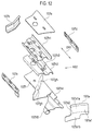
- Fig. 12 is an exploded view of the load transmission member 107L.
- Fig. 13 is a set of views of the load transmission member 107L at three different angles. Parts (a), (b), and (c) of Fig. 13 are front, bottom, and right-side views, respectively, in the state of being attached to the side extension member 104L.
- Fig. 14 is a cross-sectional view taken along line S1-S1 in part (b) of Fig. 13 .
- a bolt BT2 is inserted into the bolt hole 107gv and fastened to an internally threaded portion (not shown) provided in the upper surface of the add-on member 104Lb.
- the axis of the bolt BT2 will also be referred to as the fixing axis CL7.
- Part (d) of Fig. 20 shows a state after a certain period of time has further elapsed.
- the outer surface 107a1 is formed as a curved surface which is inclined and recessed from the outer side, and therefore has a shape in conformity with the outer shape of the obstacle ST as compared to a case where the outer surface 107a1 is a simple flat surface.
- This curved surface allows a larger area of contact between the obstacle ST and the outer surface 107a1 and accordingly reduces the stress in the outer surface 107a1 and its periphery caused by the collision load F.
- local deformation of the load transmission member 107L is reduced, and the collision load F therefore attenuates only slightly at the load transmission member 107L.
- the collision load F is then transmitted from the outer surface 107a1 of the outer side wall section 107a to the outer surface 107b1 of the inner side wall section 107b.
- the collision load F can be transmitted more efficiently to the powertrain102.
- the collision angle is such that the lateral force fy is always dominant at any point of time during the collision between the obstacle ST and the load transmission member 107L.
- the load transmission to the powertrain 102 through the load transmission member 107L is done more efficiently.
- these positions P7L, P7R are set forward of the coupling line LN9.
- the load transmission member 107L, 107R transmits a moving force F7 to the powertrain 102 in a collision with the obstacle ST
- the front side of the powertrain 102 changes its direction to the direction of the moving force F7.
- the vehicle body M traveling forward moves while changing its direction to a direction corresponding to the transmitted moving force F7.
- the vehicle body M moves away from the obstacle ST. In this way, the influence of the obstacle ST on the vehicle body M can be reduced.
Landscapes
- Engineering & Computer Science (AREA)
- Chemical & Material Sciences (AREA)
- Combustion & Propulsion (AREA)
- Transportation (AREA)
- Mechanical Engineering (AREA)
- Body Structure For Vehicles (AREA)
Abstract
Description
- The present invention relates to a front vehicle body structure.
- A technique described in
Patent Literature 1 has heretofore been known as a measure for small overlap collision. The small overlap collision refers to a collision in which an obstacle collides with a vehicle body from the front side of the vehicle body at a position outward, in the vehicle width direction, from a side member provided at a side section of the vehicle body along the front-rear direction. - In the technique described in
Patent Literature 1, a bumper reinforcement is provided at the front end of the side member, the bumper reinforcement being provided along the vehicle width direction. Further, a reinforcement extension is provided to extent rearward from an outer end portion of the bumper reinforcement in the vehicle width direction. The reinforcement extension includes a protruding section formed to protrude toward the side member. At the time of the small overlap collision, the protruding section comes into contact with the side member to exert a resistive force. Moreover, at the moment of the contact, the protruding section is received by a stopper bracket provided on the side member so that the side member can be prevented from being displaced rearward. - Patent Literature 1:
Japanese Patent Unexamined Publication No. 2008-213739 - Meanwhile, the conventional front vehicle body structure may undergo, for example, full overlap collision or the like in which a collision load is exerted on each side member from the front side of the vehicle body. In this case, the reinforcement extension, which is disposed along the side member, interferes and makes it difficult for the side member to be crushed. Consequently, the amount of deformation of the side member is reduced, and the impact absorption performance may possibly be lowered.
- The present invention has been made in view of such a problem in the conventional technique, and an object thereof is to provide a front vehicle body structure which has achieved enhanced performance of absorbing collision load from the front side of the vehicle.
- A front vehicle body structure according to an aspect of the present invention includes: a member provided at a side section of a vehicle body along a vehicle-body front-rear direction; and a powertrain disposed on an inner side of the vehicle body relative to the member. The front vehicle body structure further includes a load transmission member provided on the member and configured to come into contact with one end portion, in a vehicle width direction, of the powertrain when receiving a collision load applied by an obstacle from a front side of the vehicle body, and to transmit the collision load to the powertrain in a state of being sandwiched between the obstacle and the powertrain.
-
- [
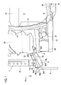
Fig. 1] Fig. 1 is a plan view of a left portion of a front section of a vehicle body showing a front vehicle body structure according to a first embodiment. - [
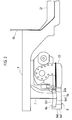
Fig. 2] Fig. 2 is a side view showing the front vehicle body structure inFig. 1 . - [
Fig. 3] Fig. 3 is a perspective view showing a main section of the front vehicle body structure inFig. 1 . - [
Fig. 4] Fig. 4 is an explanatory view of the operation of the front vehicle body structure inFig. 1 showing how the vehicle body is deformed in a small overlap collision. - [
Fig. 5] Fig. 5 is a side view showing another example of a load transmission member along with a powertrain. - [
Fig. 6] Fig. 6 is a view for explaining the operation of the front vehicle body structure inFig. 1 at the initial stage of a full overlap collision. - [
Fig. 7] Fig. 7 is an explanatory view of the operation followingFig. 6 . - [
Fig. 8] Fig. 8 is an explanatory view of the operation followingFig. 7 . - [
Fig. 9] Fig. 9 is a perspective view for explaining a front vehicle body structure according to a second embodiment. - [
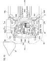
Fig. 10] Fig. 10 is a bottom view for explaining the front vehicle body structure. - [
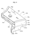
Fig. 11] Fig. 11 is a perspective view for explaining one of load transmission members in the front vehicle body structure. - [
Fig. 12] Fig. 12 is an exploded view for explaining the load transmission member. - [
Fig. 13] Fig. 13 is a set of views at three different angles for explaining the load transmission member. - [
Fig. 14] Fig. 14 is a cross-sectional view taken along line S1-S1 inFig. 13 . - [
Fig. 15] Fig. 15 is a perspective view for explaining a state where the load transmission member is attached to a side extension member. - [
Fig. 16] Fig. 16 is a top view for explaining the state where the load transmission member is attached to the side extension member. - [
Fig. 17] Fig. 17 is a bottom view for explaining the behavior of the front vehicle body structure undergoing a small overlap collision. - [
Fig. 18] Fig. 18 is a schematic view for explaining a collision load applied to the load transmission member. - [
Fig. 19] Fig. 19 is a graph for explaining a component of a force of the collision load. - [
Fig. 20] Fig. 20 is a set of bottom views for explaining the behavior of the vehicle body undergoing the small overlap collision. - [
Fig. 21] Fig. 21 is a side view showing a state before a collision for explaining the absorption of the collision energy by a suspension member in the front vehicle body structure. - [
Fig. 22] Fig. 22 is a side view showing a state after the collision in relation toFig. 21 . - [
Fig. 23] Fig. 23 is a set of front views for explaining turning in a collision in a case where a load transmission member is used. - [
Fig. 24] Fig. 24 is a front view for explaining turning in a collision in a case where the load transmission member is used. - [
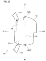
Fig. 25] Fig. 25 is a schematic view of a powertrain and each load transmission member as seen from below. - Embodiments of the present invention will now be described in detail with reference to the drawings. Note that the dimensional proportions in the drawings may be exaggerated for convenience and differ from the actual proportions.
-
Fig. 1 shows a front vehicle body structure according to a first embodiment of the present invention.Fig. 1 shows the initial state of collision of a left front section of avehicle body 1 with anobstacle 3. Note that in the drawings, the direction shown by arrow FR is the front side of the vehicle body and the direction shown by arrow LH is the left side of the vehicle body. - A pair of
front side members 5 as side members is provided along the vehicle-body front-rear direction (left-right direction inFig. 1 ) at the opposite sections of thevehicle body 1 in the vehicle width direction. As shown inFigs. 2 and3 , at a lower portion of eachfront side member 5 around the front side of the vehicle body, the upper end of acoupling member 7 provided along the vertical direction (the direction perpendicular to the plane of the sheet ofFig. 2 ) is coupled. Further, the lower end of thecoupling member 7 is coupled to an upper portion of aload transmission member 9. Also, theload transmission member 9 is coupled to an end portion, in the vehicle width direction, of across member 11 provided along the vehicle width direction. Details of the shape of theload transmission member 9 will be described later. - As shown in
Fig. 1 , adash panel 13 is disposed on the rear side of the vehicle body relative to thecross member 11. Relative to thedash panel 13, anengine compartment 15 is formed on the front side of the vehicle body and acabin 17 is formed on the rear side of the vehicle body. Thecabin 17 includes afloor panel 19 at the bottom. At the center of thefloor panel 19 in the vehicle width direction, acenter tunnel section 21 is formed which is provided along the vehicle-body front-rear direction and protrudes toward the upper side of the vehicle body (toward the front surface of the sheet ofFig. 1 ). - The
engine compartment 15 is an area surrounded by the left and rightfront side members 5, thecross member 11, and thedash panel 13, and apowertrain 23 which includes an engine and a transmission is disposed in this area. Moreover, thepowertrain 23 is mounted to the left and rightfront side members 5 through mount brackets not shown. - A
hood ridge panel 25 is provided outward, in the vehicle width direction, from eachfront side member 5 in theengine compartment 15. Moreover, astrut tower 27 is provided inward from thehood ridge panel 25 in the vehicle width direction near thedash panel 13. A hood ridgelower front section 28 is formed on a front lower side of thestrut tower 27. Also, afront pillar 29 is located on the rear side of the vehicle relative to thehood ridge panel 25. Further, the front end of aside sill 31 which is provided along the vehicle-body front-rear direction is coupled to the lower end of thefront pillar 29. - As shown in
Fig. 3 , theload transmission member 9 includes: abase section 9a which has a flat and substantially cuboidal shape and a protrudingsection 9b which has a long and substantially cuboidal shape and protrudes upward from the top of thebase section 9a. Here, as for theload transmission member 9 inFig. 3 , its longitudinal direction in a plan view seen in the vertical direction of the vehicle body will be referred to as the X direction, and a direction perpendicular to the X direction will be referred to as the Y direction. - The protruding
section 9b is provided along the X direction substantially on the center of thebase section 9a in the Y direction. A front end surface 9a1 of thebase section 9a on the front side of the vehicle body is such that its inner side in the vehicle width direction is bent at a bent portion 9a2 toward the rear side of the vehicle body, thereby forming a bent surface 9a11. Also, the bent portion 9a2 is located to substantially coincide with the inner edge of the protrudingsection 9b in the vehicle width direction. As a result, the front end surface 9a1 is in a shape protruding toward the front side of the vehicle body. Likewise, as shown inFig. 1 , a rear end surface 9a3 of thebase section 9a on the rear side of the vehicle body is such that its inner side in the vehicle width direction is bent at a bent portion 9a4 toward the rear side of the vehicle body. Also, the bent portion 9a4 is located to coincide with the inner edge of the protrudingsection 9b in the vehicle width direction. As a result, the rear end surface 9a3 is in a shape recessed toward the front side of the vehicle body. - As shown in
Figs. 2 and3 , an upper surface 9b1 of the protrudingsection 9b is formed as a concave curved surface, and a side surface 9b2 of the protrudingsection 9b on the outer side in the vehicle width direction is also formed as a concave curved surface. Moreover, an upper surface 9a5 of thebase section 9a located on the outer side in the vehicle width direction is also formed as an concave curved surface like the upper surface 9b1 of the protrudingsection 9b. In sum, in this embodiment, concave curved surfaces are formed in the surface of theload transmission member 9 along the vehicle-body front-rear direction. - As shown in
Fig. 1 , while attached to thefront side member 5 and thecoupling member 7, thisload transmission member 9 as a whole is such that a section thereof on the front side of the vehicle body is located outward from a section thereof on the rear side of the vehicle body in the vehicle width direction. In order words, theload transmission member 9 is inclined in the vehicle-body left-right direction with respect to the vehicle-body front-rear direction. - Here, while the
load transmission member 9 is attached to thevehicle body 1, a side surface 9a6 of thebase section 9a on the inner side in the vehicle width direction, on the front side of the vehicle body, is in contact with and fixed to an end portion in thevehicle width direction 11a of thecross member 11 through anattachment 33. On the other hand, the lower end of thecoupling member 7 shown inFigs. 2 and3 is fixed substantially to the center, in the X direction, of the upper surface 9a5 of thebase section 9a on the outer side in the vehicle width direction. Thus, theload transmission member 9 is provided between thefront side member 5 and thecross member 11. - Moreover, as shown in
Fig. 1 , the rear end surface 9a3 of thebase section 9a and a rear end surface 9b3 of the protrudingsection 9b on the rear side of the vehicle body face acorner portion 23a of thepowertrain 23 located at a front section thereof on the outer side in the vehicle width direction. Also, while theload transmission member 9 is attached as described above, the rear end surface 9a3 and the rear end surface 9b3 are spaced away from thecorner portion 23a by a certain distance. - Description will now be given of the path of transmission of a collision load applied when a vehicle including the above-described front vehicle body structure collides from the front side with the
obstacle 3 such as another automobile, as shown inFig. 1 . Note that the collision here is assumed to be collision of theobstacle 3 with a spot around thefront side member 5 on the left side in the vehicle width direction. This collision with the spot around thefront side member 5 includes small overlap collision in which the obstacle collides at a position outward from thefront side member 5 in the vehicle width direction. - In the small overlap collision, when the
obstacle 3 reaches theload transmission member 9 through afront bumper 35 shown inFig. 4 , theload transmission member 9 is moved toward the rear side of the vehicle body along with thecross member 11 and thecoupling member 7, which are attached to theload transmission member 9. By this movement, the rear end surfaces 9a3, 9b3 on the rear side of theload transmission member 9 come into contact with thecorner portion 23a of thepowertrain 23, which is located at the front section thereof on the outer side in the vehicle width direction, and thereby transmit the collision load thereto. The direction of this load transmission is the direction of arrow F inFig. 1 which corresponds to the longitudinal direction of theload transmission member 9. Here, thefront side member 5 is formed to be more fragile at a section thereof on the front side of the vehicle body relative to thecoupling member 7 than a section thereof on the rear side of the vehicle relative to thecoupling member 7. Hence, the fragile front section is crushed. - Moreover, since the direction of the load transmission is the direction of arrow F during the above-mentioned movement, the
load transmission member 9 and thepowertrain 23 turn counterclockwise inFigs. 1 and4 with theload transmission member 9 sandwiched between theobstacle 3 and thepowertrain 23. Here, theload transmission member 9 and thepowertrain 23 turn while maintaining substantially the same relative positions with each other. Note that the upper surface 9b1 and the side surface 9b2 on the outer side in the vehicle width direction of the protrudingsection 9b of theload transmission member 9 as well as the upper surface 9a5 of theload transmission member 9 are formed as concave curved surfaces. Thus, when the load is transmitted, these curved surfaces are elastically deformed to be curved further, which reduces the likelihood of fracture of theload transmission member 9. Hence, the load transmission can be done efficiently. - As shown in
Fig. 4 , thepowertrain 23, which turns as described above, turns counterclockwise about a fulcrum around a portion thereof mounted to thefront side member 5 at an end portion on the right side in the vehicle width direction (upper side inFig. 4 ). In this turn, thepowertrain 23 transmits the load thereto such that arear portion 23b on the left side in the vehicle width direction comes into contact with around thecenter tunnel section 21 of thefloor panel 19. A stiffness of thecenter tunnel section 21 is higher than other flat portions of thefloor panel 19 on which the occupants place their feet. Thus, the turn of thepowertrain 23 can be stopped by thecenter tunnel section 21 at an earlier stage and the deformation of thecabin 17 can therefore be reduced to be smaller. Note that a section of thecabin 17 located on the lower side of the vehicle body relative to thedash panel 13 shown inFig. 1 is shown, and thedash panel 13 is therefore not shown inFig. 4 . - Moreover, using the inertia force of the
powertrain 23 generated by its turn, the whole vehicle body moves laterally toward the right side in the vehicle width direction (upper side inFig. 4 ) so as to bring theobstacle 3 away from thefront pillar 29. As a result, the deformation of thecabin 17 by theobstacle 3 is reduced. Meanwhile, broken line P inFig. 1 is the trajectory of theobstacle 3 after the collision. As the vehicle body 1 (front pillar 29) moves laterally toward the upper side inFig. 4 , theobstacle 3 moves in the direction opposite to this lateral movement, which is toward the lower side inFig. 4 . By the above-described features, the front vehicle body structure of this embodiment can achieve enhanced performance of absorbing collision load from the front side of the vehicle. - As mentioned above, the
load transmission member 9 is disposed between thefront side member 5 and thecross member 11. Moreover, the end portion of theload transmission member 9 on the rear side of the vehicle body protrudes only slightly into theengine compartment 15. Hence, flexibility is ensured for the layout of components inside theengine compartment 15. - Also, in this embodiment, the
load transmission member 9 is elastically deformed in the state of being sandwiched between theobstacle 3 and thepowertrain 23 and receiving a load, which reduces the likelihood of fracture of theload transmission member 9. Hence, the load transmission to thepowertrain 23 can be done efficiently. - Here, in this embodiment, the
load transmission member 9 has concave curved surfaces formed in the surface (the upper surface 9b1, the side surface 9b2, and the upper surface 9a5) thereof along the vehicle-body front-rear direction. Also, the concave curved surfaces are elastically deformed to be curved further in the state of receiving the load, which further reduces the likelihood of fracture of theload transmission member 9. Hence, the load transmission to thepowertrain 23 can be done more efficiently. - Note that the shape of the rear end surfaces 9a3, 9b3, which are the portions of the
load transmission member 9 at which it comes into contact with thepowertrain 23, is one important feature for theload transmission member 9 to remain sandwiched between thepowertrain 23 and theobstacle 3 after coming into contact with thepowertrain 23. - For this reason, in this embodiment, the rear end surface 9a3 is bent at the bent portion 9a4 to have a shape recessed toward the front side of the vehicle body. In this way, this recessed portion can receive the
corner portion 23a of thepowertrain 23 and ensure theload transmission member 9 to remain sandwiched between thepowertrain 23 and theobstacle 3. In this case, the shape of the rear end surfaces 9a3, 9b3 of theload transmission member 9 is designed in conformity with the shape of thecorner portion 23a, which is the portion of thepowertrain 23 where it comes into contact with theload transmission member 9. With this shape, theload transmission member 9 can remain sandwiched between thepowertrain 23 and theobstacle 3. - Alternatively, a shape as shown in
Fig. 5 may be employed as another example of the above embodiment. Specifically, the rear end surface 9a3 of aload transmission member 9A on the side where it comes into contact with thepowertrain 23 may have a shape that accommodates the difference in strength (material) between anupper section 23U and alower section 23L of a housing of thepowertrain 23. - In this case, as shown in
Fig. 5 , the housing of thepowertrain 23 includes theupper section 23U made of an aluminum alloy and thelower section 23L serving as an oil pan made of iron higher in stiffness than theupper section 23U. Here, when theload transmission member 9 comes into contact with thepowertrain 23 as shown inFig. 4 , theupper section 23U and thelower section 23L are located to coincide with the protrudingsection 9b and thebase section 9a, respectively. - Also, a recessed
section 9c to enter for thelower section 23L with higher stiffness is provided in the rear end surface 9a3 of thebase section 9a which is located to coincide with thelower section 23L. The recessedsection 9c is formed at a position which is substantially at the center in the Y direction and substantially under the protrudingsection 9b. When theload transmission member 9 comes into contact with thepowertrain 23 as shown inFig. 4 , theupper section 23U with lower rigidity is crushed rearward to the position of a two-dot chain line shown inFig. 5 whereas thelower section 23L with higher rigidity enters the recessedsection 9c of theload transmission member 9 since it is harder to crush. Note that theload transmission member 9 is made of iron like thelower section 23L. - In this way, it is easier for the
load transmission member 9 to remain sandwiched between theobstacle 3 and thepowertrain 23 after coming into contact with thepowertrain 23. Hence, the load transmission by the following turning movement can be done efficiently. - Using
Figs. 6 to 8 , description will now be given of full overlap collision in which substantially the entire area of thevehicle body 1 in the vehicle width direction collides with anobstacle 3A such as another automobile, or moderate overlap collision in which theobstacle 3A collides at a position that covers at least one of the left and rightfront side members 5. - In this case, the
obstacle 3A comes into contact with theload transmission member 9 at a contact portion Q through the front bumper not shown. This contact portion Q corresponds to the bent surface 9a11 located inward from the bent portion 9a2 in the vehicle width direction. Further, the contact portion Q is located outward, in the vehicle width direction, from thecorner portion 23a of thepowertrain 23, at which it comes into contact with theload transmission member 9. In other words, in this embodiment, the contact portion Q of theload transmission member 9 on the front side of the vehicle body which comes into contact with theobstacle 3A is located outward, in the vehicle width direction, from a contact portion R of theload transmission member 9 on the rear side of the vehicle body which comes into contact with thepowertrain 23. Also, the direction of the load transmission during the contact mentioned above is the direction of arrow F which is substantially in parallel with the vehicle-body front-rear direction. - For this reason, after coming into contact at the contact portion Q with the
powertrain 23 as shown inFig. 6 , theload transmission member 9 comes into contact at the rear end surface 9a3 with thecorner portion 23a of thepowertrain 23 as shown inFig. 7 . Then, thewhole powertrain 23 turns counterclockwise inFig. 7 about the contact portion R. Thereafter, as shown inFig. 8 , theload transmission member 9 moves such that the X direction (longitudinal direction) is substantially in parallel with the vehicle width direction with the front end surface 9a1 located on the outer side in the vehicle width direction and the rear end surface 9a3 located on the inner side in the vehicle width direction. In this case, theload transmission member 9 starts turning at an earlier stage than it does in the small overlap collision inFigs. 1 and4 , so that the load transmission from theload transmission member 9 to thepowertrain 23 is stopped at an earlier stage. Hence, the deformation of thecabin 17 by thepowertrain 23 can be reduced. - Also, in this case, since the
load transmission member 9 starts turning at an earlier stage as mentioned above, it is accordingly easier for thefront side member 5 to be crushed. As a result, thefront side member 5 is deformed by a sufficient amount. Hence, the impact absorption performance can be enhanced. - As described above, the front vehicle body structure according to this embodiment includes: a member provided at the side section of the vehicle body along the vehicle-body front-rear direction; and the
powertrain 23 disposed on the inner side of the vehicle body relative to the member and fixed to the front section of the vehicle body. The front vehicle body structure further includes the load transmission member provided on the member and configured to come into contact with one end portion, in the vehicle width direction, of the powertrain when receiving a collision load applied by an obstacle from the front side of the vehicle body, and to transmit the load to the powertrain in the state of being sandwiched between the obstacle and the powertrain. - Also, the front vehicle body structure according to this embodiment further includes the
cross member 11 provided along the vehicle width direction. Moreover, in this embodiment, the member is a pair of left and right side members provided at the respective side sections of the vehicle body along the vehicle-body front-rear direction, and thecross member 11 couples the pair of left and right side members to each other. Furthermore, theload transmission member 9 is provided between each of the side members and the cross member and transmits the collision load to thepowertrain 23 while turning along with the powertrain in the state of being sandwiched between theobstacle 3 and the powertrain. In this way, the collision load received by the load transmission member is efficiently transmitted to the vehicle body through the powertrain. Hence, the performance of absorbing collision load from the front side of the vehicle body can be enhanced. - While this embodiment is described above, the present invention is not limited to the embodiment. For example, the
load transmission member 9 is coupled to theend portion 11a of thecross member 11 in the vehicle width direction in the embodiment, but theload transmission member 9 can be coupled to the upper surface of thecross member 11. In other words, in this case, theload transmission member 9 is coupled to thecross member 11 and thecoupling member 7 in such a way as to be sandwiched between thecross member 11 on the lower side and thecoupling member 7 on the upper side. Such a coupled state can also achieve similar advantageous effects. Note that although the left side of the vehicle body is described in the embodiment, the load transmission member is also provided similarly on the right side of the vehicle body. - A front vehicle body structure according to a second embodiment of the present invention will be described with reference to
Figs. 9 to 25 . Note that in the drawings, the direction shown by arrow FR is the front side of the vehicle body and the direction shown by arrow RR is the rear side of the vehicle body. Also, the direction shown by arrow RH is the right side of the vehicle body and the direction shown by arrow LH is the left side of the vehicle body. - First, a front vehicle body structure MK will be described with reference to
Figs. 9 and10 .Fig. 9 is a perspective view of a front section of a vehicle body M as seen diagonally from a left front upper side for explaining the front vehicle body structure MK. Some members are omitted to facilitate the understanding.Fig. 10 is a bottom view of the front section of the vehicle body M for explaining the front vehicle body structure MK. - A pair of
front side members front side members - The space between the pair of
front side members powertrain 102 is disposed and supported at the opposite sides in the width direction on thefront side members powertrain 102 includes an engine disposed on the right side of the vehicle body M and atransmission 102B disposed on the left side of the vehicle body M. Support positions 102SL, 102SR of thepowertrain 102 on thefront side members Fig. 9 and by + symbols inFig. 10 . - A
dash panel 103 is disposed behind the engine compartment RM1, and a cabin RM2 is provided behind thedash panel 103. - A
suspension member 104 is provided below thefront side members suspension member 104 is formed in such a way as to couple a pair of left andright side sills powertrain 102. Thesuspension member 104 includes: aside extension member 104L provided on the left side of the vehicle body M along the vehicle-body front-rear direction; and aside extension member 104R provided on the right side of the vehicle body M along the vehicle-body front-rear direction. Thesuspension member 104 further includes acoupling part 104M coupling the rear end sides of theside extension members side extension member 104L is formed by: a base member 104La on the rear side; and an add-on member 104Lb coupled to the front end of the base member 104La through a coupling portion P1 and extending forward therefrom. - The front side members 101 and the
side extension members suspension member 104 form a side member assembly KG. The pair of left and rightside extension members powertrain 102 therebetween. - Front end portions of the
side extension members suspension member 104 and front end portions of thefront side members strut parts side extension members suspension member 104 are coupled to each other by a lower support (cross member) 106 configured to support a radiator core not shown. -
Load transmission members side extension members suspension member 104 behind the portions thereof where thestrut parts load transmission members Fig. 10 . - The
load transmission member 107L and theload transmission member 107R are formed substantially plane-symmetrical with each other. For this reason, the structure of theload transmission member 107L will be representatively described with reference toFigs. 11 to 14 . -
Fig. 11 is a perspective view of theload transmission member 107L in substantially the same posture as that shown inFig. 9 .Fig. 12 is an exploded view of theload transmission member 107L.Fig. 13 is a set of views of theload transmission member 107L at three different angles. Parts (a), (b), and (c) ofFig. 13 are front, bottom, and right-side views, respectively, in the state of being attached to theside extension member 104L.Fig. 14 is a cross-sectional view taken along line S1-S1 in part (b) ofFig. 13 . - The
load transmission member 107L includes, as exterior members, an outerside wall section 107a, an innerside wall section 107b, afront wall section 107c, arear wall section 107d, atop plate section 107e, and abottom wall section 107f. By assembling these members, ahousing 107g is formed which has a space SP1 therein. The outerside wall section 107a has an outer surface 107a1 formed as a curved surface, in particular, a surface curved concavely in an arch shape in a plan view. Moreover, the outer surface 107a1 is formed to include an upper surface 107a1a (first surface) on the upper side of the vehicle body and a lower surface 107a1b (second surface) on the lower side of the vehicle body. At the center of the outer surface 107a1 in the vertical direction, a stepped portion 107a2 is provided such that the lower surface 107a1b protrudes to a position outward from the upper surface 107a1a and is formed with the same curvature as the upper surface 107a1a. - As shown in
Fig. 12 , thehousing 107g houses therein an upper plate 107h1, a lower plate 107h2, a stay 107h3, a sub plate 107h4, and a pipe 107h5 as a structural part assembly KG2. Housing the structural part assembly KG2 can improve the stiffness of theload transmission member 107L. Note that inFig. 14 , positions at which welding is performed on the structural part assembly KG2 are shown with ▲ symbols. The welding can be arc welding or spot welding, for example. - The upper plate 107h1, the lower plate 107h2, the stay 107h3, and the sub plate 107h4 include protruding portions, bent portions, and the like along the direction in which the outer
side wall section 107a and the innerside wall section 107b are connected (the direction of arrow DR1). The pipe 107h5 is formed with its axis aligned in the direction of arrow DR1. In this way, theload transmission member 107L is formed to have high stiffness in the direction of arrow DR1. Hereinafter, this direction in which the outerside wall section 107a and the innerside wall section 107b are connected will also be referred to as the load transmission direction DR1. - The
housing 107g of theload transmission member 107L has bolt holes at three positions for fixing theload transmission member 107L to its counterpart with bolts. Specifically, there are a bolt hole 107gv (seeFig. 11 andFig. 13(b) ) for fixing in the vertical direction and bolt holes 107gh at two positions for fixing in the horizontal direction. The bolt holes 107gh are formed in thebottom wall section 107f. In the front vehicle body structure MK, the counterpart to which theload transmission member 107L is fixed through the bolt holes 107gv, 107gh at the three positions is theside extension member 104L of thesuspension member 104. - The state where the
load transmission member 107L is fixed to theside extension member 104L will now be described with reference toFig. 15 . The add-on member 104Lb of theside extension member 104L is formed in an angular tube shape having a substantially horizontal upper surface and a substantially vertical outer side surface (seeFig. 24 ). Theload transmission member 107L is fixed to the add-on member 104Lb of theside extension member 104L with bolts BT1, BT2. Specifically, from the left side of the vehicle body M, two bolts BT1 are inserted into the bolt holes 107gh which are formed in thebottom wall section 107f and fastened to internally threaded portions not shown provided in the outer side surface of the add-on member 104Lb. Moreover, from the upper side, a bolt BT2 is inserted into the bolt hole 107gv and fastened to an internally threaded portion (not shown) provided in the upper surface of the add-on member 104Lb. Hereinafter, the axis of the bolt BT2 will also be referred to as the fixing axis CL7. - Thus, the
load transmission member 107L is fastened with bolts in two axial directions, namely, the width direction and the vertical direction of the vehicle body M, and thebottom wall section 107f is fixed to both the upper surface and the outer side surface of the rectangular add-on member 104Lb. In this way, displacement and loosening are less likely to occur. Hence, theload transmission member 107L and the add-on member 104Lb are firmly fixed to each other as one member. - The
load transmission member 107L fixed to thesuspension member 104 has the following features in term of shape.Fig. 16 is a view of a left front section of the vehicle body M as seen from a position under thefront side member 101L (see arrow Y1 inFig. 9 ). - The
load transmission member 107L is fixed to the add-on member 104Lb in such a posture as to project therefrom diagonally forward while extending toward the outer side of the vehicle body M, and diagonally rearward while extending toward the inner side of the vehicle body M. In other words, thehousing 107g is attached in such a way as to straddle the add-on member 104Lb in the width direction. In such a state, an angle θa between the load transmission direction DR1 and an axis CL1 in the vehicle-body front-rear direction is 0° < θa < 90°. The angle θa is approximately 65°, for example. - On the outer surface 107a1 of the outer
side wall section 107a of theload transmission member 107L, a rear end 107a3 is an apex 107j which is the portion of theload transmission member 107L protruding furthest in the width direction. Also, a straight line inFig. 16 connecting a tip 107a4 (first position) and the apex 107j (second position) will be referred to as the inclination line LN1, the tip 107a4 being a portion of the outer surface 107a1 where it joins the add-on member 104Lb. Here, an angle θb as the interior angle between the inclination line LN1 and the axis CL1 in the vehicle-body front-rear direction is equal to or smaller than 45°. Also, the outer surface 107a1 is a curved surface recessed inward from the inclination line LN1 in the width direction of the vehicle body M. - An outer surface 107b1 of the inner
side wall section 107b of theload transmission member 107L protrudes to a position on the inner side of the vehicle body relative to theside extension member 104L, and faces a left front end portion (corner portion) 102Lt of thepowertrain 102. Further, the outer surface 107b1 is formed to include a bent portion 107b1a where theouter surface 107b is recessed at the center. This bent portion 107b1a is formed in conformity with the shape of the leftfront end portion 102 Lt of thepowertrain 102. - The structures and configurations of the
load transmission member 107L and the add-on member 104Lb described above apply also to theload transmission member 107R and an add-on member 104Rb which are symmetrical therewith about the center axis of the vehicle body M. - Description will now be given of the transmission of a collision load and the behavior of each member in a small overlap collision at the left front section of the vehicle body M with reference to
Figs. 17 to 20 . An obstacle ST that collides with the vehicle body M in the small overlap collision is shown, for example, inFig. 10 in contact with the front bumper M2. - In
Fig. 17 , in relation toFig. 10 , a state where the vehicle body M undergoes a small overlap collision with the obstacle ST as a result of moving toward the left is shown as relative movement of the obstacle ST. InFig. 17 , the front bumper M2 is not shown.Fig. 17 shows a state where the obstacle ST has deformed the front end portion of thefront side member 101L and the front end portion of theside extension member 104L of thesuspension member 104 and collided with the outer surface 107a1 of theload transmission member 107L.Fig. 18 is a schematic view for explaining a collision load F resulting from the collision of the obstacle ST with the outer surface 107a1. -
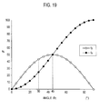
Fig. 19 is a graph for explaining the relationship between an axial force fx and a lateral force fy derived from the collision load F, and the angle of inclination of the collided portion. First, the component of the force of the collision load F will be described with reference toFigs. 18 and19 . - The outer surface 107a1 is inclined to be separated outwardly further away from the vehicle body M as extending from the front side to the rear side of the vehicle body M. For this reason, as shown in
Fig. 18 , assuming that the obstacle ST collides with the outer surface 107a1 at a collision point P2, the collision load F applied to theload transmission member 107L is divided into a component f1 along a tangential line LN2 at the collided portion and a component f2 perpendicular to the tangential line LN2. Further, the component f2 is divided into the axial force fx in parallel with the axis CL1 in the front-rear direction and the lateral force fy perpendicular to the axis CL1. Here, the tangential line LN2 is assumed to be inclined at an angle θc with respect to the axis CL1 in the front-rear direction. - Each force is described as follows.


- The relationship in magnitude between the axial force fx and the lateral force fy is dependent on the angle θc and is shown in
Fig. 19 . InFig. 19 , the horizontal axis shows the angle θc (0° to 90°) while the vertical axis shows the percentage of each force such that the axial force fx is 100% when the angle θc is 90°, i.e. when the collided surface is perpendicular to the direction of the collision. As is clear from the graph, the axial force fx and the lateral force fy match each other when the angle θc is 45°. Further, the axial force fx is greater than the lateral force fy when the angle θc is within a range of from above 45° to 90°. Furthermore, the lateral force fy is greater than the axial force fx when the angle θc is within a range of from above 0° to below 45°. - The collision of the obstacle ST with the
load transmission member 107L in the small overlap collision will be described under assumption of the points mentioned above. The obstacle ST collides with the outer surface 107a1, which is inclined with respect to the direction of the collision load F to be located further outward as extending rearward. Theload transmission member 107L has relatively high stiffness since it is provided with the structural part assembly KG2. It is therefore mainly the add-on member 104Lb that is greatly deformed, and theload transmission member 107L is moved toward a rear inner side. By this movement toward the rear inner side, the innerside wall section 107b of theload transmission member 107L comes into contact with the leftfront end portion 102 Lt of thepowertrain 102. - Having high rigidity particularly in the load transmission direction DR1, the
load transmission member 107L is deformed only slightly even when colliding with thepowertrain 102. For this reason, as shown inFig. 17 , the collision load is transmitted efficiently to thepowertrain 102 as a force toward a right rear side (moving force F7). - The
powertrain 102 is large in mass and therefore large in inertia force. Moreover, the moving force F7, which originates from the collision of the obstacle ST, is large enough to change the moving direction of the vehicle body M along with thepowertrain 102. That is, upon receipt of the moving force F7 applied from theload transmission member 107L to the leftfront end portion 102 Lt, thepowertrain 102 moves toward the right side of the vehicle body M. Due to this movement, the vehicle body M changes its direction in such a way as to move away from the obstacle ST toward the right side. - With the front vehicle body structure MK, the collision load applied to the
load transmission member 107L in the small overlap collision is transmitted to thepowertrain 102 at high efficiency. Such load transmission changes the moving direction of thepowertrain 102, which is large in mass, and also changes the moving direction of the vehicle body M. - As described above, in the front vehicle body structure MK, the
load transmission member 107L is attached to theside extension member 104L of thesuspension member 104. Theload transmission member 107L includes the outerside wall section 107a which protrudes outward further in the width direction as extending toward the rear side of the vehicle body, and the innerside wall section 107b which projects from theside extension member 104L to a position inward from theside extension member 104L in the width direction and near thepowertrain 102. Then, when a collision load toward the rear side of the vehicle body M is applied to the outerside wall section 107a, theside extension member 104L is deformed and the innerside wall section 107b comes into contact with thepowertrain 102. As a result, the collision load applied to the outerside wall section 107a is transmitted at high efficiency to thepowertrain 102, which is in contact with the innerside wall section 107b, through theload transmission member 107L. In this way, the performance of absorbing the collision energy applied by collision from the front side of the vehicle body is further improved. - Moreover, the front vehicle body structure MK consumes the collision energy not only by deforming the
suspension member 104 but also by changing the moving directions of thepowertrain 102 and the vehicle body M. That is, the collision energy can be absorbed by also converting it into an energy that moves the vehicle body M away from the obstacle ST. Thus, the front vehicle body structure MK can achieve improved performance of absorbing the collision energy applied by collision from the front side of the vehicle body. - The course of change in the direction of the vehicle body M by the application of the moving force F7 to the powertrain102 is shown in
Fig. 20. Fig. 20 is a set of schematic views of the vehicle body M as seen from below and shows changes in state in the small overlap collision with the obstacle ST. Note that inFig. 20 , abumper reinforcement 108 is illustrated which couples the tips of thefront side members coupling part 104M of the suspension member in the width direction is set as a reference point P3 for convenience. Note that the center portion is a portion that deforms to a relatively small extent in the collision with the obstacle ST. - Part (a) of
Fig. 20 shows a state immediately before the small overlap collision with the obstacle ST, and the vehicle body M is traveling forward in the direction of arrow DR2. Part (b) ofFig. 20 shows a state immediate after the small overlap collision with the obstacle ST. In this state, thebumper reinforcement 108 and thelower support 106 are deformed toward the right side (see arrow DR3) and the add-on member 104Lb is crushed. By the crush of the add-on member 104Lb and the collision of the obstacle ST with the outer surface 107a1, theload transmission member 107L is moved toward the right rear side and collides with the left front end portion 102Lt of thepowertrain 102. This collision applies the moving force F7 to thepowertrain 102. The reference point P3 moves from a position P3a to a position P3b. The trajectory of that movement is shown as a trajectory LN4a. - Since this part (b) of
Fig. 20 shows the state immediately after the collision, the trajectory LN4a shifts slightly to the right side near the position P3b but is mostly straight. Due to the application of the moving force F7, the traveling direction of thepowertrain 102 shifts to a diagonally right forward direction. This directional shift of thepowertrain 102 changes the posture of the vehicle body M such that its front section is swung toward the right side along with thepowertrain 102. - Part (c) of
Fig. 20 shows a state after the collision where theload transmission member 107L is moved away from the obstacle ST. In this state, the moving direction of the vehicle body M shifts toward the diagonally right forward direction with the front side swung toward the right side. For this reason, a trajectory LN4b of the reference point P3 from the position P3b to a position P3c in the above state is inclined greatly toward a right front side. - Part (d) of
Fig. 20 shows a state after a certain period of time has further elapsed. With thepowertrain 102 swung greatly toward the right side by the moving force F7, collision between the obstacle ST and theside sill 109L is avoided. This eliminates direct influences such as entrance of the obstacle ST into the cabin RM2. Hence, the deformation of the cabin RM2 is reduced. - A trajectory LN4 clarifies the movement of the vehicle body M. Specifically, the trajectory LN4 of the reference point P3 from the position P3a to a position P3d is straight from the position P3a to a position Ps at which the collision occurs, and abruptly changes its direction toward the right front side after the collision. Thus, the trajectory LN4 passes a position far from the obstacle ST. Hence, the influence of the collision on the vehicle body M is reduced.
- Here, behavior during the short period of time in which the obstacle ST and the
load transmission member 107L come into contact with each other due to the collision will be described with reference toFigs. 16 and19 , for example. As mentioned above, the outer surface 107a1 of theload transmission member 107L is recessed inward from the inclination line LN1 in the width direction of the vehicle body M. - First of all, the outer surface 107a1 is formed as a curved surface which is inclined and recessed from the outer side, and therefore has a shape in conformity with the outer shape of the obstacle ST as compared to a case where the outer surface 107a1 is a simple flat surface. This curved surface allows a larger area of contact between the obstacle ST and the outer surface 107a1 and accordingly reduces the stress in the outer surface 107a1 and its periphery caused by the collision load F. As result, local deformation of the
load transmission member 107L is reduced, and the collision load F therefore attenuates only slightly at theload transmission member 107L. The collision load F is then transmitted from the outer surface 107a1 of the outerside wall section 107a to the outer surface 107b1 of the innerside wall section 107b. Hence, the collision load F can be transmitted more efficiently to the powertrain102. - Also, the time of contact between the obstacle ST and the outer surface 107a1 is longer. As a result, the time for the
load transmission member 107L to transmit the collision load F to thepowertrain 102 is longer. Hence, the collision load F can be transmitted more efficiently to thepowertrain 102. - The behavior will be described in more detail. In the following description, to facilitate the understanding, the obstacle ST is assumed to come into point contact in the collision in
Fig. 16 . Moreover, for convenience, the angle θc of a tangential line LN5 at a contact point P5 is assumed as the collision angle. - In this case, as shown in
Fig. 16 , since the outer surface 107a1 is a concave curved surface, the contact point P5 for the obstacle ST is the tip 107a4 at the beginning of the collision. The collision angle at this tip 107a4 is an angle θc1 between a tangential line LN6 at the tip 107a4 and the axis CL1 in the front-rear direction and is smaller than the angle θa. That is, the collision angle at the tip 107a4 represents a collision at a smaller angle than the angle θb between the inclination line LN1, which connects the tip 107a4 and the apex 107j, and the axis CL1 in the front-rear direction. - As described above, the front vehicle body structure MK is advantageously such that a portion of the outer
side wall section 107a on the front side of the vehicle body is formed in a concave arched shape in a plan view. In this way, the obstacle ST collides with the outerside wall section 107a at a shallower angle. This reduces the generation of a force in the front-rear direction which the vehicle body M receives in the collision. - In the course of the collision, the contact point P5 moves on the outer surface 107a1 from the tip 107a4 toward the apex 107j, and the angle θc, which is the collision angle, increases with this movement. If, for example, the add-on member 104Lb is not crushed or other members are not deformed by the collision, the angle θc becomes larger than the angle θb when the contact point P5 reaches the apex 107j.
- On the other hand, the
load transmission member 107L changes its posture due to crush or the like of, for example, the add-on member 104Lb by the collision such that theload transmission member 107L is pushed in. In this change, as shown by arrow DR4 inFig. 16 , the position of the apex 107j moves toward the center of the vehicle body M. Thus, the angle θb between the tangential line LN5 at the apex 107j after the movement and the axis CL1 in the front-rear direction is smaller than that before the collision. - In view of this, the initial position of the
load transmission member 107L, the curvature of the outer surface 107b1 and the like are advantageously set such that the angle θb in the pushed-in posture after the collision is not larger than 45°. In other words, the collision angle θc at the contact point P5 is advantageously maintained to be not larger than 45° while the contact point P5 moves from the tip 107a4 to the apex 107j with the elapse of time in the collision. - According to
Fig. 19 , the lateral force fy is dominant over the axial force fx when the angle θc, which is the collision angle, is equal to or smaller than 45°. For this reason, the outerside wall section 107a is advantageously formed such that the interior angle between the inclination line LN1 and the axis CL1 in the front-rear direction of the vehicle body is equal to or smaller than 45°. Here, the inclination line LN1 is a straight line connecting the tip 107a4, as the first position at which the outerside wall section 107a joins theside extension member 104L, and the apex 107j, as the second position at which the outerside wall section 107a protrudes outwardly furthest in the vehicle width direction. In this way, the collision angle is such that the lateral force fy is always dominant at any point of time during the collision between the obstacle ST and theload transmission member 107L. Hence, the load transmission to thepowertrain 102 through theload transmission member 107L is done more efficiently. - The absorption of the collision energy by the
suspension member 104 will now be described with reference toFig. 21. Fig. 21 is a left-side view showing theside extension member 104L of thesuspension member 104 and thefront side member 101L along with thedash panel 103. InFig. 21 , an area AR1 on the front side of theside extension member 104L and an area AR2 on the front side of thefront side member 101L are formed as sections that are mainly deformed in a frontal collision. In other words, the area AR1 and the area AR2 are energy absorption areas E. - In particular, the
side extension member 104L is advantageously provided with an energy absorption portion 104Lc between theload transmission member 107L which is attached to the add-on member 104Lb and the coupling portion P1 through which the add-on member 104Lb is coupled to the base member 104La. The energy absorption portion 104Lc has a structure that is easily deformable by pressure. -
Fig. 22 is a view showing a state after a frontal collision in relation toFig. 21 . Thefront side member 101L is deformed mostly at the energy absorption area E to absorb the energy. Theside extension member 104L is deformed greatly at the energy absorption portion 104Lc to absorb the energy, and the deformation of the rest of the energy absorption area E is small. - As described above, in the front vehicle body structure MK, the
side extension member 104L is advantageously provided with the energy absorption portion 104Lc, which is deformable more easily than the rest of theside extension member 104L, at a portion of theside extension member 104L on the rear side of the vehicle body relative to the load transmission member. In this way, in a frontal collision, theside extension member 104L is deformed mainly at the energy absorption portion, which allows theside extension member 104L to be deformed in a predetermined manner. As a result, the posture of theload transmission member 107L in which it comes into contact with thepowertrain 102 is stabilized, and the collision load is therefore transmitted more reliably to thepowertrain 102. Hence, the performance of absorbing the collision energy applied by collision from the front side of the vehicle body is maintained at a light level. - The
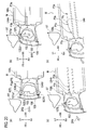
load transmission member 107L may be a load transmission member 107LA without the stepped portion 107a2 on the outer surface 107a1. The load transmission member 107LA, however, has a possibility of being turned about the longitudinal axis of theside extension member 104L, i.e. about the axis CL1 in the front-rear direction when theside extension member 104L is deformed in a small overlap collision. - Part (a) of
Fig. 23 is a front view of the load transmission member 107LA for explaining a state where this turn occurs. As shown in part (a) ofFig. 23 , in the load transmission member 107LA, the outer surface 107a1 of the outerside wall section 107a is an even curved surface with no step. - Most part of the
housing 107g of the load transmission member 107LA is disposed above theside extension member 104L. In part (a) ofFig. 23 , an upper left section of thehousing 107g relative to a center P4 projects greatly. Then, when the obstacle ST collides with an entire vertical region on the outer surface 107a1 (a region shown by a dashed line LN7 inFig. 23(a) ) at once, a counterclockwise turning force is generated. Thus, the energy absorption portion 104Lc is crushed and, at the same time, its posture is turned counterclockwise (see arrow DR5). As a result, the tip side of theside extension member 104L relative to the energy absorption portion 104Lc appears tilted toward the left side along with the load transmission member 107LA, as shown inFig. 23(b) . In this way, the efficiency of load transmission to thepowertrain 102 may possibly be lower than that with theload transmission member 107L. - On the other hand, the
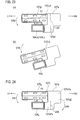
load transmission member 107L includes the stepped portion 107a2 on the outer surface 107a1 of the outerside wall section 107a. Moreover, as shown inFig. 24 , the outer surface below the position of the center P4 is the lower surface 107a1b, and this lower surface 107a1b protrudes outward from the upper surface 107a1a above the position of the center P4. Then, when the obstacle ST collides with the outer surface 107a1, it firstly collides with only the lower surface 107a1b (a region shown by a dashed line LN8 inFig. 24 ) and then collides with the upper surface 107a1a after the elapse of a certain period of time. - In the collision with the lower surface 107a1b, the obstacle ST collides at a position below the center P4, so that a clockwise turning force is generated (arrow DR6). On the other hand, in the collision with the upper surface 107a1a, a counterclockwise turning force is generated (arrow DR5).
- As described above, in the front vehicle body structure MK, the
side extension member 104L is formed in an angular tube shape. Moreover, theload transmission member 107L is fixed to the upper surface and the outer side surface, in the vehicle width direction, of theside extension member 104L. Further, the outerside wall section 107a and the innerside wall section 107b are coupled to each other in such a way as to straddle the upper side of theside extension member 104L. - Moreover, the outer
side wall section 107a has the upper surface 107a1a which is the first surface on the upper side and the lower surface 107a1b which is the second surface on the lower side. Further, the second surface (lower surface 107a1p) is advantageously formed to protrude outward from the first surface (upper surface 107a1a) in the vehicle width direction. In this way, the clockwise turning force generated by the obstacle ST colliding firstly with the lower surface 107a1b is cancelled out by the counterclockwise turning force generated by the obstacle ST colliding thereafter with the upper surface 107a1a. Theside extension member 104L therefore hardly turns when the energy absorption portion 104Lc is crushed. Thus, theload transmission member 107L comes into contact with thepowertrain 102 with substantially no turning. Hence, theload transmission member 107L can transmit the collision load at high efficiency to thepowertrain 102. -
Fig. 25 is a schematic view of thepowertrain 102 and theload transmission members load transmission members side wall section 107b with thepowertrain 102 at a position P7L, P7R (contact position P7L, P7R) in a small overlap collision with the obstacle ST. An imaginary straight line connecting a support position 102SL and a support position 102SR at which thepowertrain 102 is supported on thefront side members - Suppose that the positions P7L, P7R are located rearward of the coupling line LN9. In this case, when a moving force F7 is transmitted to the
powertrain 102, the rear side of thepowertrain 102 changes its direction to the direction of the moving force F7. For this reason, the vehicle body M traveling forward changes its direction to the direction opposite to the direction of the transmitted moving force F7. As a result, the vehicle body M moves toward the obstacle ST and is therefore more greatly influenced by the obstacle ST. - On the other hand, in the front vehicle body structure MK, these positions P7L, P7R are set forward of the coupling line LN9. For this reason, when the
load transmission member powertrain 102 in a collision with the obstacle ST, the front side of thepowertrain 102 changes its direction to the direction of the moving force F7. Thus, as shown inFig. 20 , the vehicle body M traveling forward moves while changing its direction to a direction corresponding to the transmitted moving force F7. Hence, the vehicle body M moves away from the obstacle ST. In this way, the influence of the obstacle ST on the vehicle body M can be reduced. - As described above, the front vehicle body structure MK includes the pair of
front side members powertrain 102 from the opposite sides in the vehicle width direction. Moreover, the pair offront side members powertrain 102 at the pair of support positions 102SL, 102SR on the opposite sides in the width direction thereof. Furthermore, the positions P7L, P7R, at which the innerside wall sections 107b come into contact with thepowertrain 102, are advantageously located on the front side of the vehicle body relative to the coupling line LN9, which passes the support positions 102SL, 102SR. In this way, when theload transmission member powertrain 102 in a collision with the obstacle ST, the front side of thepowertrain 102 changes its direction to the direction of the moving force F7. Then, the vehicle body M traveling forward moves while changing its direction to a direction corresponding to the transmitted moving force F7. In other words, the vehicle body M moves away from the obstacle ST. Hence, the influence of the collision of the obstacle ST on the vehicle body M can be reduced. - In the front vehicle body structure MK, the
load transmission members front side members side extension members suspension member 104. In this way, the collision performance of thefront side members - As compared to the conventional reinforcement extension, the front vehicle body structure MK can reduce the amount of projection toward the outer side in the vehicle width direction and therefore has a high degree of freedom in design for exteriors that narrow on the front side of the vehicle body.
- As described above, like the first embodiment, the front vehicle body structure according to this embodiment also includes: a member which is provided at the side section of the vehicle body along the vehicle-body front-rear direction; and the
powertrain 102 disposed on the inner side of the vehicle body relative to the member and fixed to the front section of the vehicle body. The front vehicle body structure further includes the load transmission member provided on the member and configured to come into contact with one end portion, in the vehicle width direction, of the powertrain when receiving a collision load applied by an obstacle from the front side of the vehicle body, and to transmit the load to the powertrain in a state of being sandwiched between the obstacle and the powertrain. - Further, in this embodiment, the member is the
suspension member 104 including the pair of left and rightside extension members 104 provided along the vehicle-body front-rear direction in such a way as to sandwich thepowertrain 102 from the opposite sides in the vehicle width direction. Also, the load transmission member 107 is attached to theside extension member 104. Moreover, the load transmission member includes: the outerside wall section 107a being formed to project outward further in the vehicle width direction from the side extension member as extending toward to the rear side of the vehicle body; and the innerside wall section 107b projecting from the side extension member to a position inward from the side extension member in the vehicle width direction and being disposed to face the powertrain. Further, theside extension member 104 is deformed to bring the innerside wall section 107b into contact with thepowertrain 102 when the collision load is applied to the outerside wall section 107a of the load transmission member 107. As described above, the collision load is transmitted at high efficiency through the load transmission member to the powertrain which is in contact with the inner side wall section. Hence, the collision energy applied by a collision from the front side of the vehicle body can be absorbed efficiently. - The entire contents of
Japanese Patent Application No. 2013-079151 (filed on April 5, 2013 Japanese Patent Application No. 2013-173402 (filed on August 23, 2013 - The content of the present invention has been described above through embodiments. However, it is apparent to those skilled in the art that the present invention is not limited this description and various changes and modifications can be made.
- According to the present invention, when receiving a collision load from the front side of the vehicle, the load transmission member transmits the load from the obstacle to the powertrain while turning along with the powertrain in the state of being sandwiched between the obstacle and the powertrain. Thus, the collision load received by the load transmission member is efficiently transmitted to the vehicle body through the powertrain. Hence, enhanced performance of absorbing collision load from the front side of the vehicle body can be achieved.
-
- 1, M
- vehicle body
- 3, 3A
- obstacle
- 5, 101, 101L, 101R
- front side member
- 9, 9A, 107, 107L, 107R, 107LA
- load transmission member
- 11
- cross member
- 23, 102
- powertrain
- 102SL, 102SR
- support position
- 104
- suspension member
- 104L, 104R
- side extension member
- 104Lc
- energy absorption portion
- 107a
- outer side wall section
- 107b
- inner side wall section
- CL1
- axis in vehicle-body front-rear direction
- MK
- front vehicle body structure
Claims (12)
- A front vehicle body structure comprising:a member provided at a side section of a vehicle body along a vehicle-body front-rear direction;a powertrain disposed on an inner side of the vehicle body relative to the member and fixed to a front section of the vehicle body; anda load transmission member provided on the member and configured to come into contact with one end portion, in a vehicle width direction, of the powertrain when receiving a collision load applied by an obstacle from a front side of the vehicle body, and to transmit the load from the obstacle to the powertrain in a state of being sandwiched between the obstacle and the powertrain.
- The front vehicle body structure according to claim 1, further comprising a cross member provided along the vehicle width direction, wherein
the member is a pair of left and right side members provided at the respective side sections of the vehicle body along the vehicle-body front-rear direction,
the cross member couples the pair of left and right side members to each other, and
the load transmission member is provided between each of the side members and the cross member and transmits the collision load to the powertrain while turning along with the powertrain in the state of being sandwiched between the obstacle and the powertrain. - The front vehicle body structure according to claim 1 or 2, wherein a contact portion of the load transmission member on the front side of the vehicle body which comes into contact with the obstacle is located outside, in the vehicle width direction, from a contact portion of the load transmission member on a rear side of the vehicle body which comes into contact with the powertrain.
- The front vehicle body structure according to any one of claims 1 to 3, wherein the load transmission member is elastically deformed in the state of being sandwiched between the obstacle and the powertrain and receiving the load.
- The front vehicle body structure according to claim 4, wherein
the load transmission member has a concave curved surface formed in a surface thereof along the vehicle-body front-rear direction, and
the curved surface is elastically deformed further in the state of receiving the load. - The front vehicle body structure according to any one of claims 1 to 5, wherein a shape of a contact portion of the load transmission member which comes into contact with the powertrain is in conformity with a shape of the powertrain.
- The front vehicle body structure according to claim 1, wherein
the member is a suspension member including a pair of left and right side extension members provided along the vehicle-body front-rear direction in such a way as to sandwich the powertrain from opposite sides in the vehicle width direction,
the load transmission member is attached to the side extension members,
the load transmission member includes an outer side wall section and an inner side wall section, the outer side wall section being formed to project outward further in the vehicle width direction from the side extension member as extending toward a rear side of the vehicle body, the inner side wall section projecting from the side extension member to a position inward from the side extension member in the vehicle width direction and being disposed to face the powertrain, and
the side extension member is deformed to bring the inner side wall section into contact with the powertrain when the collision load is applied to the outer side wall section of the load transmission member. - The front vehicle body structure according to claim 7, wherein each of the side extension members includes an energy absorption portion on the rear side of the vehicle body relative to the load transmission member, the energy absorption portion being deformable more easily than a rest of the side extension member.
- The front vehicle body structure according to claim 7 or 8, wherein a portion of the outer side wall section on the front side of the vehicle body is formed in a concave arched shape.
- The front vehicle body structure according to any one of claims 7 to 9, wherein the outer side wall section is formed such that an interior angle between a straight line connecting a first position and a second position and an axis in the vehicle-body front-rear direction is equal to or smaller than 45°, the first position being a position at which the outer side wall section joins the side extension member, the second position being a position at which the outer side wall section protrudes outwardly furthest in the vehicle width direction.
- The front vehicle body structure according to any one of claims 7 to 10, wherein
each of the side extension members is formed in an angular tube shape,
the load transmission member is fixed to an upper surface and an outer side surface in the vehicle width direction of the side extension member and is formed by coupling the outer side wall section and the inner side wall section to each other in such a way to straddle a portion of the side extension member on an upper side of the vehicle body, and
the outer side wall section has a first surface on the upper side of the vehicle body and a second surface on a lower side of the vehicle body, and the second surface protrudes outward from the first surface in the vehicle width direction. - The front vehicle body structure according to any one of claims 7 to 11, further comprising a pair of side members provided along the vehicle-body front-rear direction in such a way as to sandwich the powertrain from opposite sides in the vehicle width direction, wherein
the pair of side members support the powertrain at a pair of support positions on opposite sides in a width direction thereof, and
a position at which the inner side wall section of the load transmission member comes into contact with the powertrain is on the front side of the vehicle body relative to an imaginary straight line passing the pair of support positions.
Applications Claiming Priority (3)
| Application Number | Priority Date | Filing Date | Title |
|---|---|---|---|
| JP2013079151 | 2013-04-05 | ||
| JP2013173402 | 2013-08-23 | ||
| PCT/JP2014/057663 WO2014162880A1 (en) | 2013-04-05 | 2014-03-20 | Vehicle body front portion structure |
Publications (3)
| Publication Number | Publication Date |
|---|---|
| EP2982577A1 true EP2982577A1 (en) | 2016-02-10 |
| EP2982577A4 EP2982577A4 (en) | 2016-06-29 |
| EP2982577B1 EP2982577B1 (en) | 2017-05-10 |
Family
ID=51658180
Family Applications (1)
| Application Number | Title | Priority Date | Filing Date |
|---|---|---|---|
| EP14778375.7A Active EP2982577B1 (en) | 2013-04-05 | 2014-03-20 | Vehicle body front portion structure |
Country Status (5)
| Country | Link |
|---|---|
| US (1) | US9415805B2 (en) |
| EP (1) | EP2982577B1 (en) |
| JP (1) | JP5983867B2 (en) |
| CN (1) | CN105073563B (en) |
| WO (1) | WO2014162880A1 (en) |
Families Citing this family (16)
| Publication number | Priority date | Publication date | Assignee | Title |
|---|---|---|---|---|
| DE102015110436B3 (en) * | 2015-06-29 | 2016-10-27 | Magna Steyr Fahrzeugtechnik Ag & Co. Kg | motor vehicle |
| JP6299701B2 (en) * | 2015-07-31 | 2018-03-28 | トヨタ自動車株式会社 | Vehicle lower structure |
| US10029733B1 (en) | 2017-01-12 | 2018-07-24 | Nissan North America, Inc. | Vehicle body structure |
| US10118644B2 (en) | 2017-01-12 | 2018-11-06 | Nissan North America, Inc. | Vehicle body structure |
| US10150507B2 (en) | 2017-01-12 | 2018-12-11 | Nissan North America, Inc. | Vehicle body structure |
| US10189503B2 (en) | 2017-01-12 | 2019-01-29 | Nissan North America, Inc. | Vehicle body structure |
| JP6747319B2 (en) * | 2017-02-02 | 2020-08-26 | トヨタ自動車株式会社 | Vehicle front structure |
| WO2019008747A1 (en) | 2017-07-07 | 2019-01-10 | 本田技研工業株式会社 | Front body structure |
| GB2570116B (en) * | 2018-01-10 | 2021-01-13 | Ford Global Tech Llc | Transmission roll initiator |
| US10526017B2 (en) | 2018-04-30 | 2020-01-07 | Nissan North America, Inc. | Vehicle body structure |
| US10661833B2 (en) | 2018-06-29 | 2020-05-26 | Nissan North America, Inc. | Vehicle body structure |
| US10967907B2 (en) * | 2018-10-16 | 2021-04-06 | Nissan North America, Inc. | Vehicle front end structure |
| CN112009568B (en) * | 2019-05-30 | 2022-10-28 | 马自达汽车株式会社 | Powertrain support structure of vehicle |
| US11407449B2 (en) | 2020-02-24 | 2022-08-09 | Nissan North America, Inc. | Energy absorbing structure for vehicle frame |
| US11827167B2 (en) * | 2020-06-25 | 2023-11-28 | Rivian Ip Holdings, Llc | Wheel deflector for a small overlap crash |
| US11718352B2 (en) * | 2021-06-04 | 2023-08-08 | Nissan North America, Inc. | Vehicle engine cradle structure |
Family Cites Families (14)
| Publication number | Priority date | Publication date | Assignee | Title |
|---|---|---|---|---|
| JP3861617B2 (en) * | 2001-04-27 | 2006-12-20 | 日産自動車株式会社 | Auto body front structure |
| JP3632666B2 (en) | 2002-02-01 | 2005-03-23 | 日産自動車株式会社 | Body front structure |
| JP4122887B2 (en) * | 2002-08-05 | 2008-07-23 | 日産自動車株式会社 | Body front structure |
| JP2008213739A (en) | 2007-03-06 | 2008-09-18 | Toyota Motor Corp | Bumper structure, vehicle front structure and vehicle rear structure |
| JP4695176B2 (en) * | 2008-11-25 | 2011-06-08 | 本田技研工業株式会社 | Body front structure |
| JP5329576B2 (en) * | 2011-01-26 | 2013-10-30 | 本田技研工業株式会社 | Vehicle body front |
| JP5357953B2 (en) | 2011-04-01 | 2013-12-04 | 本田技研工業株式会社 | Body front structure |
| JP5477594B2 (en) | 2011-04-25 | 2014-04-23 | マツダ株式会社 | Vehicle front structure |
| JP5468101B2 (en) * | 2012-03-27 | 2014-04-09 | 富士重工業株式会社 | Body front structure |
| JP5949939B2 (en) * | 2012-11-16 | 2016-07-13 | 日産自動車株式会社 | Body front structure |
| JP5692210B2 (en) * | 2012-12-07 | 2015-04-01 | トヨタ自動車株式会社 | Body front structure |
| US8985258B1 (en) * | 2014-05-30 | 2015-03-24 | Ford Global Technologies, Llc | Vehicle frame component |
| US9233716B2 (en) * | 2014-05-30 | 2016-01-12 | Ford Global Technologies, Llc | Vehicle frame component |
| KR101575335B1 (en) * | 2014-08-13 | 2015-12-07 | 현대자동차 주식회사 | Structure for reinforcing front vehicle body |
-
2014
- 2014-03-20 JP JP2015509993A patent/JP5983867B2/en active Active
- 2014-03-20 WO PCT/JP2014/057663 patent/WO2014162880A1/en not_active Ceased
- 2014-03-20 US US14/782,336 patent/US9415805B2/en active Active
- 2014-03-20 EP EP14778375.7A patent/EP2982577B1/en active Active
- 2014-03-20 CN CN201480019587.9A patent/CN105073563B/en active Active
Also Published As
| Publication number | Publication date |
|---|---|
| EP2982577A4 (en) | 2016-06-29 |
| WO2014162880A1 (en) | 2014-10-09 |
| CN105073563A (en) | 2015-11-18 |
| US9415805B2 (en) | 2016-08-16 |
| EP2982577B1 (en) | 2017-05-10 |
| US20160023681A1 (en) | 2016-01-28 |
| CN105073563B (en) | 2016-10-12 |
| JPWO2014162880A1 (en) | 2017-02-16 |
| JP5983867B2 (en) | 2016-09-06 |
Similar Documents
| Publication | Publication Date | Title |
|---|---|---|
| EP2982577B1 (en) | Vehicle body front portion structure | |
| EP2921377B1 (en) | Structure for front part of vehicle | |
| US8672393B2 (en) | Front vehicle body structure | |
| US9010849B2 (en) | Front subframe structure for automotive vehicle | |
| CN107031725A (en) | Car body fore part arrangement | |
| EP3626586B1 (en) | Suspension sub frame structure | |
| JP6511078B2 (en) | Electric car floor structure | |
| US20200101914A1 (en) | Vehicle body rear structure | |
| CN110077469B (en) | body structure | |
| JPWO2019043770A1 (en) | Vehicle rear structure | |
| US20180273094A1 (en) | Front sub-frame structure | |
| US10717469B2 (en) | Vehicle body front part structure | |
| JP2012153258A (en) | Front body of vehicle | |
| US20120001456A1 (en) | Frontal structure of vehicle | |
| JP2015034001A (en) | Vehicle body front part structure | |
| CN109866826B (en) | Vehicle body mounting bracket for vehicle | |
| JP5954204B2 (en) | Front body structure of the vehicle | |
| CN215245126U (en) | Dashboard cross member assembly for vehicle and vehicle | |
| KR102394581B1 (en) | Front vehicle body reinforcing structure | |
| CN110962936B (en) | Cross member structure and vehicle frame | |
| JP5513904B2 (en) | Front body structure of the vehicle | |
| JP7496065B2 (en) | Vehicle front structure | |
| WO2016207968A1 (en) | Vehicle body front structure | |
| JP6292088B2 (en) | Vehicle front structure | |
| JP7314695B2 (en) | vehicle front structure |
Legal Events
| Date | Code | Title | Description |
|---|---|---|---|
| PUAI | Public reference made under article 153(3) epc to a published international application that has entered the european phase |
Free format text: ORIGINAL CODE: 0009012 |
|
| 17P | Request for examination filed |
Effective date: 20151016 |
|
| AK | Designated contracting states |
Kind code of ref document: A1 Designated state(s): AL AT BE BG CH CY CZ DE DK EE ES FI FR GB GR HR HU IE IS IT LI LT LU LV MC MK MT NL NO PL PT RO RS SE SI SK SM TR |
|
| AX | Request for extension of the european patent |
Extension state: BA ME |
|
| A4 | Supplementary search report drawn up and despatched |
Effective date: 20160531 |
|
| RIC1 | Information provided on ipc code assigned before grant |
Ipc: B62D 25/20 20060101AFI20160524BHEP Ipc: B62D 25/08 20060101ALI20160524BHEP |
|
| DAX | Request for extension of the european patent (deleted) | ||
| GRAP | Despatch of communication of intention to grant a patent |
Free format text: ORIGINAL CODE: EPIDOSNIGR1 |
|
| STAA | Information on the status of an ep patent application or granted ep patent |
Free format text: STATUS: GRANT OF PATENT IS INTENDED |
|
| INTG | Intention to grant announced |
Effective date: 20170206 |
|
| GRAS | Grant fee paid |
Free format text: ORIGINAL CODE: EPIDOSNIGR3 |
|
| GRAA | (expected) grant |
Free format text: ORIGINAL CODE: 0009210 |
|
| STAA | Information on the status of an ep patent application or granted ep patent |
Free format text: STATUS: THE PATENT HAS BEEN GRANTED |
|
| AK | Designated contracting states |
Kind code of ref document: B1 Designated state(s): AL AT BE BG CH CY CZ DE DK EE ES FI FR GB GR HR HU IE IS IT LI LT LU LV MC MK MT NL NO PL PT RO RS SE SI SK SM TR |
|
| REG | Reference to a national code |
Ref country code: GB Ref legal event code: FG4D |
|
| REG | Reference to a national code |
Ref country code: AT Ref legal event code: REF Ref document number: 892005 Country of ref document: AT Kind code of ref document: T Effective date: 20170515 Ref country code: CH Ref legal event code: EP |
|
| REG | Reference to a national code |
Ref country code: IE Ref legal event code: FG4D |
|
| REG | Reference to a national code |
Ref country code: DE Ref legal event code: R096 Ref document number: 602014009784 Country of ref document: DE |
|
| REG | Reference to a national code |
Ref country code: NL Ref legal event code: MP Effective date: 20170510 |
|
| REG | Reference to a national code |
Ref country code: LT Ref legal event code: MG4D |
|
| REG | Reference to a national code |
Ref country code: AT Ref legal event code: MK05 Ref document number: 892005 Country of ref document: AT Kind code of ref document: T Effective date: 20170510 |
|
| PG25 | Lapsed in a contracting state [announced via postgrant information from national office to epo] |
Ref country code: ES Free format text: LAPSE BECAUSE OF FAILURE TO SUBMIT A TRANSLATION OF THE DESCRIPTION OR TO PAY THE FEE WITHIN THE PRESCRIBED TIME-LIMIT Effective date: 20170510 Ref country code: AT Free format text: LAPSE BECAUSE OF FAILURE TO SUBMIT A TRANSLATION OF THE DESCRIPTION OR TO PAY THE FEE WITHIN THE PRESCRIBED TIME-LIMIT Effective date: 20170510 Ref country code: LT Free format text: LAPSE BECAUSE OF FAILURE TO SUBMIT A TRANSLATION OF THE DESCRIPTION OR TO PAY THE FEE WITHIN THE PRESCRIBED TIME-LIMIT Effective date: 20170510 Ref country code: HR Free format text: LAPSE BECAUSE OF FAILURE TO SUBMIT A TRANSLATION OF THE DESCRIPTION OR TO PAY THE FEE WITHIN THE PRESCRIBED TIME-LIMIT Effective date: 20170510 Ref country code: GR Free format text: LAPSE BECAUSE OF FAILURE TO SUBMIT A TRANSLATION OF THE DESCRIPTION OR TO PAY THE FEE WITHIN THE PRESCRIBED TIME-LIMIT Effective date: 20170811 Ref country code: FI Free format text: LAPSE BECAUSE OF FAILURE TO SUBMIT A TRANSLATION OF THE DESCRIPTION OR TO PAY THE FEE WITHIN THE PRESCRIBED TIME-LIMIT Effective date: 20170510 Ref country code: NO Free format text: LAPSE BECAUSE OF FAILURE TO SUBMIT A TRANSLATION OF THE DESCRIPTION OR TO PAY THE FEE WITHIN THE PRESCRIBED TIME-LIMIT Effective date: 20170810 |
|
| PG25 | Lapsed in a contracting state [announced via postgrant information from national office to epo] |
Ref country code: PL Free format text: LAPSE BECAUSE OF FAILURE TO SUBMIT A TRANSLATION OF THE DESCRIPTION OR TO PAY THE FEE WITHIN THE PRESCRIBED TIME-LIMIT Effective date: 20170510 Ref country code: LV Free format text: LAPSE BECAUSE OF FAILURE TO SUBMIT A TRANSLATION OF THE DESCRIPTION OR TO PAY THE FEE WITHIN THE PRESCRIBED TIME-LIMIT Effective date: 20170510 Ref country code: IS Free format text: LAPSE BECAUSE OF FAILURE TO SUBMIT A TRANSLATION OF THE DESCRIPTION OR TO PAY THE FEE WITHIN THE PRESCRIBED TIME-LIMIT Effective date: 20170910 Ref country code: SE Free format text: LAPSE BECAUSE OF FAILURE TO SUBMIT A TRANSLATION OF THE DESCRIPTION OR TO PAY THE FEE WITHIN THE PRESCRIBED TIME-LIMIT Effective date: 20170510 Ref country code: BG Free format text: LAPSE BECAUSE OF FAILURE TO SUBMIT A TRANSLATION OF THE DESCRIPTION OR TO PAY THE FEE WITHIN THE PRESCRIBED TIME-LIMIT Effective date: 20170810 Ref country code: NL Free format text: LAPSE BECAUSE OF FAILURE TO SUBMIT A TRANSLATION OF THE DESCRIPTION OR TO PAY THE FEE WITHIN THE PRESCRIBED TIME-LIMIT Effective date: 20170510 Ref country code: RS Free format text: LAPSE BECAUSE OF FAILURE TO SUBMIT A TRANSLATION OF THE DESCRIPTION OR TO PAY THE FEE WITHIN THE PRESCRIBED TIME-LIMIT Effective date: 20170510 |
|
| PG25 | Lapsed in a contracting state [announced via postgrant information from national office to epo] |
Ref country code: CZ Free format text: LAPSE BECAUSE OF FAILURE TO SUBMIT A TRANSLATION OF THE DESCRIPTION OR TO PAY THE FEE WITHIN THE PRESCRIBED TIME-LIMIT Effective date: 20170510 Ref country code: EE Free format text: LAPSE BECAUSE OF FAILURE TO SUBMIT A TRANSLATION OF THE DESCRIPTION OR TO PAY THE FEE WITHIN THE PRESCRIBED TIME-LIMIT Effective date: 20170510 Ref country code: RO Free format text: LAPSE BECAUSE OF FAILURE TO SUBMIT A TRANSLATION OF THE DESCRIPTION OR TO PAY THE FEE WITHIN THE PRESCRIBED TIME-LIMIT Effective date: 20170510 Ref country code: DK Free format text: LAPSE BECAUSE OF FAILURE TO SUBMIT A TRANSLATION OF THE DESCRIPTION OR TO PAY THE FEE WITHIN THE PRESCRIBED TIME-LIMIT Effective date: 20170510 Ref country code: SK Free format text: LAPSE BECAUSE OF FAILURE TO SUBMIT A TRANSLATION OF THE DESCRIPTION OR TO PAY THE FEE WITHIN THE PRESCRIBED TIME-LIMIT Effective date: 20170510 |
|
| REG | Reference to a national code |
Ref country code: DE Ref legal event code: R097 Ref document number: 602014009784 Country of ref document: DE |
|
| REG | Reference to a national code |
Ref country code: FR Ref legal event code: PLFP Year of fee payment: 5 |
|
| PG25 | Lapsed in a contracting state [announced via postgrant information from national office to epo] |
Ref country code: SM Free format text: LAPSE BECAUSE OF FAILURE TO SUBMIT A TRANSLATION OF THE DESCRIPTION OR TO PAY THE FEE WITHIN THE PRESCRIBED TIME-LIMIT Effective date: 20170510 Ref country code: IT Free format text: LAPSE BECAUSE OF FAILURE TO SUBMIT A TRANSLATION OF THE DESCRIPTION OR TO PAY THE FEE WITHIN THE PRESCRIBED TIME-LIMIT Effective date: 20170510 |
|
| PLBE | No opposition filed within time limit |
Free format text: ORIGINAL CODE: 0009261 |
|
| STAA | Information on the status of an ep patent application or granted ep patent |
Free format text: STATUS: NO OPPOSITION FILED WITHIN TIME LIMIT |
|
| 26N | No opposition filed |
Effective date: 20180213 |
|
| PG25 | Lapsed in a contracting state [announced via postgrant information from national office to epo] |
Ref country code: SI Free format text: LAPSE BECAUSE OF FAILURE TO SUBMIT A TRANSLATION OF THE DESCRIPTION OR TO PAY THE FEE WITHIN THE PRESCRIBED TIME-LIMIT Effective date: 20170510 |
|
| REG | Reference to a national code |
Ref country code: CH Ref legal event code: PL |
|
| PG25 | Lapsed in a contracting state [announced via postgrant information from national office to epo] |
Ref country code: MC Free format text: LAPSE BECAUSE OF FAILURE TO SUBMIT A TRANSLATION OF THE DESCRIPTION OR TO PAY THE FEE WITHIN THE PRESCRIBED TIME-LIMIT Effective date: 20170510 |
|
| REG | Reference to a national code |
Ref country code: BE Ref legal event code: MM Effective date: 20180331 |
|
| REG | Reference to a national code |
Ref country code: IE Ref legal event code: MM4A |
|
| PG25 | Lapsed in a contracting state [announced via postgrant information from national office to epo] |
Ref country code: LU Free format text: LAPSE BECAUSE OF NON-PAYMENT OF DUE FEES Effective date: 20180320 |
|
| PG25 | Lapsed in a contracting state [announced via postgrant information from national office to epo] |
Ref country code: IE Free format text: LAPSE BECAUSE OF NON-PAYMENT OF DUE FEES Effective date: 20180320 |
|
| PG25 | Lapsed in a contracting state [announced via postgrant information from national office to epo] |
Ref country code: LI Free format text: LAPSE BECAUSE OF NON-PAYMENT OF DUE FEES Effective date: 20180331 Ref country code: BE Free format text: LAPSE BECAUSE OF NON-PAYMENT OF DUE FEES Effective date: 20180331 Ref country code: CH Free format text: LAPSE BECAUSE OF NON-PAYMENT OF DUE FEES Effective date: 20180331 |
|
| PG25 | Lapsed in a contracting state [announced via postgrant information from national office to epo] |
Ref country code: MT Free format text: LAPSE BECAUSE OF NON-PAYMENT OF DUE FEES Effective date: 20180320 |
|
| PG25 | Lapsed in a contracting state [announced via postgrant information from national office to epo] |
Ref country code: TR Free format text: LAPSE BECAUSE OF FAILURE TO SUBMIT A TRANSLATION OF THE DESCRIPTION OR TO PAY THE FEE WITHIN THE PRESCRIBED TIME-LIMIT Effective date: 20170510 |
|
| PG25 | Lapsed in a contracting state [announced via postgrant information from national office to epo] |
Ref country code: PT Free format text: LAPSE BECAUSE OF FAILURE TO SUBMIT A TRANSLATION OF THE DESCRIPTION OR TO PAY THE FEE WITHIN THE PRESCRIBED TIME-LIMIT Effective date: 20170510 |
|
| PG25 | Lapsed in a contracting state [announced via postgrant information from national office to epo] |
Ref country code: CY Free format text: LAPSE BECAUSE OF FAILURE TO SUBMIT A TRANSLATION OF THE DESCRIPTION OR TO PAY THE FEE WITHIN THE PRESCRIBED TIME-LIMIT Effective date: 20170510 Ref country code: HU Free format text: LAPSE BECAUSE OF FAILURE TO SUBMIT A TRANSLATION OF THE DESCRIPTION OR TO PAY THE FEE WITHIN THE PRESCRIBED TIME-LIMIT; INVALID AB INITIO Effective date: 20140320 Ref country code: MK Free format text: LAPSE BECAUSE OF NON-PAYMENT OF DUE FEES Effective date: 20170510 |
|
| PG25 | Lapsed in a contracting state [announced via postgrant information from national office to epo] |
Ref country code: AL Free format text: LAPSE BECAUSE OF FAILURE TO SUBMIT A TRANSLATION OF THE DESCRIPTION OR TO PAY THE FEE WITHIN THE PRESCRIBED TIME-LIMIT Effective date: 20170510 |
|
| REG | Reference to a national code |
Ref country code: DE Ref legal event code: R084 Ref document number: 602014009784 Country of ref document: DE |
|
| REG | Reference to a national code |
Ref country code: GB Ref legal event code: 746 Effective date: 20230925 |
|
| PGFP | Annual fee paid to national office [announced via postgrant information from national office to epo] |
Ref country code: GB Payment date: 20260220 Year of fee payment: 13 |
|
| PGFP | Annual fee paid to national office [announced via postgrant information from national office to epo] |
Ref country code: DE Payment date: 20260219 Year of fee payment: 13 |
|
| PGFP | Annual fee paid to national office [announced via postgrant information from national office to epo] |
Ref country code: FR Payment date: 20260219 Year of fee payment: 13 |