CN110962936B - Cross member structure and vehicle frame - Google Patents
Cross member structure and vehicle frame Download PDFInfo
- Publication number
- CN110962936B CN110962936B CN201811142768.7A CN201811142768A CN110962936B CN 110962936 B CN110962936 B CN 110962936B CN 201811142768 A CN201811142768 A CN 201811142768A CN 110962936 B CN110962936 B CN 110962936B
- Authority
- CN
- China
- Prior art keywords
- vehicle
- frame
- protrusion
- longitudinal beams
- cross beam
- Prior art date
- Legal status (The legal status is an assumption and is not a legal conclusion. Google has not performed a legal analysis and makes no representation as to the accuracy of the status listed.)
- Active
Links
Images


Classifications
-
- B—PERFORMING OPERATIONS; TRANSPORTING
- B62—LAND VEHICLES FOR TRAVELLING OTHERWISE THAN ON RAILS
- B62D—MOTOR VEHICLES; TRAILERS
- B62D21/00—Understructures, i.e. chassis frame on which a vehicle body may be mounted
- B62D21/02—Understructures, i.e. chassis frame on which a vehicle body may be mounted comprising longitudinally or transversely arranged frame members
- B62D21/03—Understructures, i.e. chassis frame on which a vehicle body may be mounted comprising longitudinally or transversely arranged frame members transverse members providing body support
-
- B—PERFORMING OPERATIONS; TRANSPORTING
- B62—LAND VEHICLES FOR TRAVELLING OTHERWISE THAN ON RAILS
- B62D—MOTOR VEHICLES; TRAILERS
- B62D21/00—Understructures, i.e. chassis frame on which a vehicle body may be mounted
- B62D21/02—Understructures, i.e. chassis frame on which a vehicle body may be mounted comprising longitudinally or transversely arranged frame members
Abstract
The invention provides a beam structure and a frame, wherein the beam structure is arranged on the frame, the frame is provided with two longitudinal beams extending along the length direction of a vehicle, the beam structure comprises a body extending along the width direction of the vehicle and fixedly arranged on the two longitudinal beams, and an upward bulge is formed in the middle of the body to enable the body to be in a shape like a Chinese character ji. The beam structure also comprises a reinforcing part which extends from one side of the notch at the bottom of the protrusion to the other side of the notch, and a depression which is opposite to the protrusion and has a downward direction is formed in the middle of the reinforcing part. The cross beam structure can provide better support for the frame, so that the intrusion amount of a vehicle to a driving cabin during side collision or column collision is reduced, and the safety of drivers and passengers is protected.
Description
Technical Field
The invention relates to the technical field of vehicle structures, in particular to a cross beam structure and a frame provided with the cross beam structure.
Background
The design of the vehicle needs to take into consideration both the performance and quality of the vehicle and the related safety regulations, for example, the factory vehicle needs to meet the requirements of full width frontal collision, offset collision, side collision, and collision resistance. And with the gradual emphasis of consumers on safety performance, the safety performance of automobiles is also more and more emphasized. Among these, the non-load-bearing vehicle frame plays a very important role in crash performance. In the prior art, a transmission cross beam and a transmission shaft cross beam are arranged at the middle section of a frame longitudinal beam, and play a main supporting role in collision and side collision of a vehicle column. But only through the support of derailleur crossbeam and transmission shaft crossbeam to the support, when the post bumped, frame intensity was lower, probably invaded the driver's cabin, brought the injury for driver and crew.
Disclosure of Invention
In view of this, the present invention is directed to a cross member structure for improving the strength of a vehicle frame, so that the vehicle frame has better safety performance.
In order to achieve the purpose, the technical scheme of the invention is realized as follows:
a cross member structure provided on a vehicle frame having two longitudinal beams extending in a vehicle length direction, the cross member structure comprising:
the body extends along the vehicle width direction and is fixedly arranged on the two longitudinal beams, and an upward bulge is formed in the middle of the body to enable the body to be shaped like a Chinese character 'ji';
and the reinforcing part extends from one side of the notch at the bottom of the protrusion to the other side of the notch, and a recess opposite to the protrusion direction is formed in the middle of the reinforcing part.
Furthermore, the body is formed by buckling and fixing an upper plate and a lower plate.
Furthermore, the body is provided with the protrusion, and a reinforcing plate is fixedly arranged between the upper plate and the lower plate.
Further, the width of the body where the protrusion is formed is greater than the width of the body on both sides of the protrusion.
Further, the cross section of the reinforcing part perpendicular to the extending direction is in an inverted U shape.
Compared with the prior art, the invention has the following advantages:
(1) the beam structure of the invention arranges the body in a shape of 'ji', which is convenient for the arrangement of a transmission shaft on a vehicle, and the arrangement of the reinforcing part can improve the strength of the beam structure, prevent the stress concentration at the projection, provide better supporting function for the frame, ensure that the frame has better strength, effectively support the vehicle body when the vehicle collides, reduce the invasion to a driving cabin and ensure that the vehicle has better safety performance.
(2) The body is formed by buckling and fixing the upper plate and the lower plate, the processing is convenient and simple, and the cost can be saved.
(3) The strength of the protrusion can be further improved by the reinforcing plate.
(4) The strength of the projection can be further improved by arranging the body of the projection to be wider than the bodies on both sides.
(5) The section of the reinforcing part is in an inverted U shape, so that the strength of the reinforcing part can be improved.
Another object of the invention is to propose a frame for vehicles with better strength and crash performance.
In order to achieve the purpose, the technical scheme of the invention is realized as follows:
a vehicle frame comprises two longitudinal beams extending along the length direction of a vehicle, and further comprises a cross beam structure.
Furthermore, the frame also comprises a transmission shaft cross beam and a transmission cross beam which extend along the width direction of the vehicle and are arranged on the two longitudinal beams at intervals, and the cross beam structure is positioned between the transmission shaft cross beam and the transmission cross beam.
Furthermore, a vehicle body limiting bracket and a vehicle body support which form collapse energy absorption are arranged on the outer sides of the two longitudinal beams.
Furthermore, the vehicle body limiting support is of a box-shaped structure with one open end, and the vehicle body limiting support is provided with one open end which is attached and welded with the longitudinal beam.
Furthermore, the lap joint length of the cross beam structure and the two longitudinal beams in the height direction of the vehicle is larger than half of the height of the longitudinal beams.
Compared with the prior art, the invention has the following advantages:
(1) the frame has higher strength due to the addition of the beam structure, and the beam structure can provide better support for the frame during vehicle collision or side collision. Therefore, the intrusion amount of the vehicle to the driving cabin during vehicle collision is reduced, and the safety of drivers and passengers is better protected.
(2) The arrangement of the vehicle body limiting bracket and the vehicle body support can collapse and absorb energy when a vehicle collides, so that the vehicle frame main body is protected, and the safety of drivers and passengers can be well protected.
(3) The vehicle body limiting support is arranged in a box shape, so that the vehicle body limiting support has higher strength and better collapsing performance.
(4) The arrangement that the lap joint height of the beam structure and the longitudinal beam is more than half of the height of the longitudinal beam can improve the connection strength of the beam structure and the longitudinal beam.
Drawings
The accompanying drawings, which are incorporated in and constitute a part of this specification, illustrate an embodiment of the invention and, together with the description, serve to explain the invention and not to limit the invention. In the drawings:
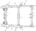
FIG. 1 is a top view of a cross member structure coupled to a vehicle frame in accordance with a first embodiment of the present invention;
fig. 2 is an overall schematic view of a beam structure according to a first embodiment of the present invention;
FIG. 3 is an exploded view of FIG. 2;
FIG. 4 is an isometric view of a cross-member structure in accordance with a first embodiment of the present invention in engagement with a vehicle frame;
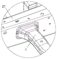
FIG. 5 is an enlarged view taken at A in FIG. 4;
FIG. 6 is a view from another angle of FIG. 4;
FIG. 7 is an enlarged view at B in FIG. 6;
fig. 8 is a schematic structural view of a vehicle body limiting bracket according to a second embodiment of the invention.
Fig. 9 is an enlarged view at C in fig. 6.
Description of reference numerals:
1-beam structure, 11-body, 111-projection, 112-upper plate, 113-lower plate, 12-reinforcement, 121-recess, 122-opening, 123-reinforcing rib, 13-reinforcing plate, 2-frame, 21-longitudinal beam, 3-transmission shaft beam, 4-transmission beam, 5-body limiting bracket, 51-first body limiting bracket, 52-second body limiting bracket and 6-body support.
Detailed Description
It should be noted that the embodiments and features of the embodiments may be combined with each other without conflict.
The present invention will be described in detail below with reference to the embodiments with reference to the attached drawings.
Example one
The present embodiment relates to a cross member structure 1, which is provided on a vehicle frame 2, wherein the vehicle frame 2 comprises two longitudinal beams 21 extending along the length direction of the vehicle. As shown in fig. 1 and 2, the cross member structure 1 includes a main body 11 extending in the vehicle width direction and fixed to the two side members 21, and an upward protrusion 111 is formed at the middle of the main body 11 to make the main body 11 in a zigzag shape. The beam structure 1 further includes a reinforcement portion 12 extending from one side of the bottom notch of the protrusion 111 to the other side of the notch, and a recess 121 is formed in the middle of the reinforcement portion 12 in a direction opposite to the direction of the protrusion 111.
Since the overall structure of the body 11 is complicated, direct molding is difficult. Therefore, in the present embodiment, as shown in fig. 2 and 3, the main body 11 is formed by fastening and welding the upper plate 112 and the lower plate 113. The upper plate 112 and the lower plate 113 are processed and formed by metal plates, punching and the like, and the upper plate 112 and the lower plate 113 are buckled and welded into the body 11 in a simple processing mode, so that the cost can be effectively saved.
In the present embodiment, the body 11 has a substantially square cross section perpendicular to the longitudinal direction of the vehicle, and an upward projection 111 is formed in the middle of the body 11. The protrusion 111 is provided to facilitate the transmission shaft of the vehicle to pass through the notch at the bottom of the protrusion 111, thereby facilitating the arrangement of the vehicle. Certainly, the arrangement of the protrusions 111 is beneficial to the arrangement of a vehicle transmission shaft, and when a vehicle is impacted by a column or a side, the vehicle can absorb energy through crumpling, so that the vehicle is protected for drivers and passengers. However, if only the projection 111 is provided, when the collision force is transmitted to the body 11 from the side member 21 during a vehicle collision, the strength of the projection 111 is too low, and the projection 111 of the body 11 may be broken too quickly, thereby failing to provide a good support function for the side member 21.
For this purpose, in this embodiment, as shown in fig. 2 and 3, a reinforcing portion 12 is further attached to the body 11, the reinforcing portion 12 extends from one side of the bottom notch of the protrusion 111 to the other side of the notch, and a downward recess 121 is formed in the middle of the reinforcing portion 12. The arrangement of the recess 121 facilitates the penetration of the transmission shaft, the strength of the protrusion 111 is increased, and the crumple performance of the protrusion 111 can be ensured, so that the vehicle protection device provides better protection for drivers and passengers, and improves the safety performance of vehicles.
In this embodiment, the reinforcing portion 12 has a structure as shown in fig. 3, and a cross section perpendicular to the extending direction thereof has an inverted "U" shape to improve the strength of the reinforcing portion 12. Both ends of the reinforcing portion 12 are fixed to the main body 11 by a pair of bolts. An opening 122 for avoiding an exhaust system is provided on one side of the reinforcement portion 12. To avoid stress concentration at this opening 122, as shown in fig. 3, a punched concave rib 123 is formed at the middle of the upper surface of the reinforcing portion 12, and the opening 122 is located approximately at the middle of the rib 123.
In order to further improve the strength at the projection 111, in the present embodiment, in addition to providing the reinforcing portion 12, as shown in fig. 3, the width of the body 11 where the projection 111 is formed is set larger than the width of the body 11 at both sides of the projection 111. And the connection between the body 11 at the protrusion 111 and the body 11 at both sides is smooth and excessive to avoid stress concentration. In the present embodiment, more specifically, the width of the body 11 at the projection 111 is 106mm, and the width of the body 11 on both sides of the projection 111 is 76 mm.
In addition to the above, in this embodiment, a reinforcing plate 13 is fixed on the body 11 between the upper plate 112 and the lower plate 113, and at the position where the protrusion 111 is formed. The reinforcing plate 13 is configured as shown in fig. 3, and is disposed along the lower plate 113, and the bottom surface of the reinforcing plate 13 is always attached and fixed to the inner surface of the lower plate 113. In order to improve the strength of the reinforcing plate 13, in the present embodiment, upward flanges are provided on both sides of the reinforcing plate 13.
The reinforcing plate 13 is fixed to the lower plate 113 by welding, and the width of the reinforcing portion 12 should be as wide as possible in order to increase the effective strength. However, this results in that both sides of the reinforcing plate 13 are closer to both sides of the lower plate 113, which makes welding difficult. On the other hand, if the reinforcing plate 13 is welded and fixed to the lower plate 113 only at both ends thereof, the reinforcing plate 13 may be instantaneously separated from the lower plate 113 and may not perform a reinforcing function at the time of a vehicle collision due to insufficient connection strength. For this purpose, in the present embodiment, as shown in fig. 3, several kidney-shaped holes are provided on the reinforcing plate 13 through the surface of the reinforcing plate 13, wherein there are three holes at least at the middle position of the top portion thereof and at the transition between the top portion and the oblique sides thereof. The strength of the connection between the reinforcing plate 13 and the lower plate 113 is improved by adding a weld bead to the lower plate 113 at the inner side line of the kidney hole. Through the combination of the modes, the strength of the protrusion 111 is reasonably enhanced while the collapse energy absorption of the protrusion 111 is kept, and the phenomenon that the protrusion 111 is too quickly collapsed and cannot achieve the energy absorption effect is avoided, so that the safety performance of the vehicle is improved.
In order to effectively transmit the force applied to the longitudinal beams 21 to the cross beam structure 1 when a vehicle collides, in the embodiment, as shown in fig. 1, two ends of the body 11 are respectively fixed to the inner side surfaces of the two longitudinal beams 21 in an overlapping manner, and the connection position of the body 11 and the longitudinal beams 21 is integrally arranged near the upper end of the inner surface of the longitudinal beam 21. As shown in fig. 2 to 7, the cross section of the tail portion of each end of the body 11 is expanded in the vehicle height direction and the vehicle width direction, so that the connection strength between the body 11 and the side member 21 is improved by increasing the area of the connection portion between the body 11 and the side member 21 and increasing the length of the weld bead connecting the body 11 and the side member 21. And more specifically, the overlapping height of the body 11 and the surface of the longitudinal beam 21 should be greater than half of the height of the longitudinal beam 21, so as to ensure that the body 11 has a better supporting effect on the longitudinal beam 21.
In order to meet the requirements of the brake system and the arrangement of the electrical system, as shown in fig. 4 and 5, the overlapping position of one end of the body 11 with the side member 21 in which the brake system is arranged is located completely inside the inner side surface of the side member 21. In order to ensure the connection strength between the cross beam structure 1 and the longitudinal beam 21, as shown in fig. 6 and 7, the other end of the body 11 is fixed to the inner side surface and the upper surface of the longitudinal beam 21 on the other side in an overlapping manner, so that the overlapping area between the body 11 and the longitudinal beam 21 is increased, and the connection strength is improved.
Example two
The present embodiment relates to a vehicle frame 2, wherein the vehicle frame 2 comprises two longitudinal beams 21 extending along the length direction of the vehicle, and further comprises a cross beam structure 1 according to the first embodiment.
By installing the cross beam structure 1 according to the first embodiment on the vehicle frame 2, the strength of the vehicle frame 2 in the width direction can be effectively improved, and the safety performance of the vehicle can be improved. As shown in fig. 1, 4 and 6, in the present embodiment, the frame 2 further includes a transmission cross member 3 and a transmission cross member 4 extending in the vehicle body width direction and overlapping the two longitudinal members 21 at an interval, and preferably, the cross member structure 1 is located between the transmission cross member 3 and the transmission cross member 4.
Because the beam structure 1 as described in the first embodiment is additionally arranged between the transmission shaft beam 3 and the transmission beam 4, the side impact strength and the column impact strength of the frame 2 are improved, and the intrusion amount to a driving cabin can be reduced when a vehicle collides, so that the safety performance of the whole vehicle is improved.
The cross member structure 1 in the present embodiment can provide effective protection in the event of a vehicle collision, but obviously, the maintenance cost is high after the vehicle is damaged. In order to effectively protect the frame 2 when the vehicle slightly collides, the main body of the frame 2 is prevented from being seriously damaged, and the maintenance cost is prevented from being overhigh. In the present embodiment, as shown in fig. 1, 4 and 6, a vehicle body stopper bracket 5 and a vehicle body support 6 for absorbing energy by collapse are further provided on the outer sides of both side members 21. In order to provide better protection for the cross beam structure 1, in the present embodiment, the body limiting bracket 5 includes a first body limiting bracket 51 and a second body limiting bracket 52, wherein the first body limiting bracket 51 is disposed near the transmission cross beam 4, and the second body limiting bracket 52 and the body support 6 are disposed on two sides of the cross beam structure 1, wherein the first body limiting bracket 51 on one side can be omitted or retained due to the body structure.
The first vehicle body limiting bracket 51 and the second vehicle body limiting bracket 52 have the same structure, and as shown in fig. 8, both have a box-shaped structure with an open end, and the open end is attached to the longitudinal beam 21 and welded and fixed. Because the first vehicle body limiting support 51 and the second vehicle body limiting support 52 are both formed by cutting, metal plates and welding plates, the material utilization rate is high. And both sides of the top surface of the vehicle body limit bracket 5 are bent and partially coated on both side surfaces to improve the strength of the vehicle body limit bracket 5 in the vehicle width direction. And the bottom part is a straight line to increase the length of the welding bead between the longitudinal beam 21 and the bottom part, thereby improving the connection strength. Because the structure of the vehicle body limiting bracket 5 is completely the same everywhere, the universality is good, and the installation is not easy to make mistakes.
The top of each vehicle body limiting bracket 5 is arranged higher than the top of the longitudinal beam 21, and the welding positions of the first vehicle body limiting bracket 51 and the second vehicle body limiting bracket 52 on the height of the longitudinal beam 21 are different. The positions of the first body stopper bracket 51 and the second body stopper bracket 52 in the height direction are determined by the vehicle body floor. The overlapping area of the vehicle body limiting bracket 5 and the vehicle body threshold beam in the vehicle height direction is guaranteed, and the energy absorption effect of the vehicle in the lateral collision is guaranteed. More specifically, in the present embodiment, the clearance between the top of each vehicle body stopper bracket 5 and the vehicle body floor is 15 mm. In this embodiment, the three side lines of the vehicle body limiting bracket 5 overlapped with the longitudinal beam 21 are all welded and fixed, and in order to ensure the connection strength between each vehicle body limiting bracket 5 and the longitudinal beam 21, the length of the welding bead of the vehicle body limiting bracket 5 in the vehicle height direction should be not less than half of the length of the side line by changing the length of the side line.
As shown in fig. 9, the vehicle body support 6 has an n-shaped cross section perpendicular to the vehicle width direction, and the cross section gradually increases from the direction away from the side member 21 to the direction toward the side member 21, and comes into contact with the vehicle body before each vehicle body stopper bracket 5 in the event of a side collision of the vehicle. During a side collision of the vehicle, the vehicle body support 6 provides protection for each vehicle body limit bracket 5 and the cross beam structure 1 through active collapse. When the vehicle body support 6 is not fully collapsed to absorb energy completely, the vehicle body limiting bracket 5 and the vehicle body support 6 are collapsed to provide protection for the beam structure 1, and when the vehicle body limiting bracket 5 and the vehicle body support 6 are fully collapsed and cannot absorb energy completely, the beam structure 1 provides support to protect the safety of people in a driving cabin. Through the setting in different stages of collapsing, when protecting and driving personnel's safety, the cost of maintenance after can also minimizing the vehicle bumps has stronger practicality.
The above description is only for the purpose of illustrating the preferred embodiments of the present invention and is not to be construed as limiting the invention, and any modifications, equivalents, improvements and the like that fall within the spirit and principle of the present invention are intended to be included therein.
Claims (7)
1. A cross member structure provided on a vehicle frame (2), said vehicle frame (2) having two longitudinal beams (21) extending in a vehicle length direction, characterized in that said cross member structure comprises:
a body (11), wherein the body (11) is formed by fastening and fixing an upper plate (112) and a lower plate (113), extends along the vehicle width direction and is fixedly arranged on the two longitudinal beams (21), an upward protrusion (111) is formed in the middle of the body (11) to enable the body (11) to be in a shape like a Chinese character 'ji', a reinforcing plate (13) is fixedly arranged between the upper plate (112) and the lower plate (113) at the position where the protrusion (111) is formed on the body (11), the reinforcing plate (13) is arranged along the lower plate (113), the bottom surface of the reinforcing plate (13) is always attached and fixed to the surface inside the lower plate (113), and the width of the body (11) at the position where the protrusion (111) is formed is larger than the width of the body (11) at the two sides of the protrusion (111);
and the reinforcing part (12) extends from one side of the notch at the bottom of the protrusion (111) to the other side of the notch, and a recess (121) opposite to the direction of the protrusion (111) is formed in the middle of the reinforcing part (12).
2. The beam structure according to claim 1, wherein: the section of the reinforcing part (12) perpendicular to the extending direction is in an inverted U shape.
3. A vehicle frame comprising two longitudinal beams (21) extending in the length direction of the vehicle, characterized in that: the frame (2) further comprises a cross-member structure (1) according to claim 1 or 2.
4. The frame of claim 3, wherein: the frame also comprises a transmission shaft cross beam (3) and a transmission cross beam (4) which extend along the width direction of the vehicle and are arranged on the two longitudinal beams (21) at intervals, and the cross beam structure (1) is positioned between the transmission shaft cross beam (3) and the transmission cross beam (4).
5. The frame of claim 4, wherein: and a vehicle body limiting bracket (5) and a vehicle body support (6) which are used for absorbing energy by collapsing are arranged on the outer sides of the two longitudinal beams (21).
6. The frame of claim 5, wherein: the vehicle body limiting support (5) is of a box-shaped structure with one open end, and the open end of the vehicle body limiting support (5) is attached to and welded and fixed with the longitudinal beam (21).
7. The frame of claim 5, wherein: the lap length of the cross beam structure (1) and the two longitudinal beams (21) in the height direction of the vehicle is larger than half of the height of the longitudinal beams (21).
Priority Applications (1)
| Application Number | Priority Date | Filing Date | Title |
|---|---|---|---|
| CN201811142768.7A CN110962936B (en) | 2018-09-28 | 2018-09-28 | Cross member structure and vehicle frame |
Applications Claiming Priority (1)
| Application Number | Priority Date | Filing Date | Title |
|---|---|---|---|
| CN201811142768.7A CN110962936B (en) | 2018-09-28 | 2018-09-28 | Cross member structure and vehicle frame |
Publications (2)
| Publication Number | Publication Date |
|---|---|
| CN110962936A CN110962936A (en) | 2020-04-07 |
| CN110962936B true CN110962936B (en) | 2021-01-05 |
Family
ID=70027904
Family Applications (1)
| Application Number | Title | Priority Date | Filing Date |
|---|---|---|---|
| CN201811142768.7A Active CN110962936B (en) | 2018-09-28 | 2018-09-28 | Cross member structure and vehicle frame |
Country Status (1)
| Country | Link |
|---|---|
| CN (1) | CN110962936B (en) |
Families Citing this family (2)
| Publication number | Priority date | Publication date | Assignee | Title |
|---|---|---|---|---|
| CN114506389A (en) * | 2020-11-16 | 2022-05-17 | 北汽福田汽车股份有限公司 | Frame cross member and vehicle |
| CN113104744B (en) * | 2021-04-29 | 2022-12-20 | 三一汽车起重机械有限公司 | Frame and crane |
Citations (7)
| Publication number | Priority date | Publication date | Assignee | Title |
|---|---|---|---|---|
| JPH06107237A (en) * | 1992-09-29 | 1994-04-19 | Mazda Motor Corp | Lower car body structure of automobile |
| CN201347134Y (en) * | 2008-11-28 | 2009-11-18 | 比亚迪股份有限公司 | Floor structure of electric vehicle |
| CN201545068U (en) * | 2009-09-22 | 2010-08-11 | 浙江吉利汽车研究院有限公司 | Vehicle side column collision strengthening structure |
| CN201777299U (en) * | 2010-07-29 | 2011-03-30 | 比亚迪股份有限公司 | Bottom structure of electric vehicle |
| CN202728365U (en) * | 2012-08-14 | 2013-02-13 | 东风汽车公司 | Structure of front floor board of automobile |
| CN203920907U (en) * | 2014-07-08 | 2014-11-05 | 安徽江淮汽车股份有限公司 | A kind of frame assembly and vehicle |
| CN207773247U (en) * | 2018-01-20 | 2018-08-28 | 日照兴业汽车配件有限公司 | Frame cross |
Family Cites Families (1)
| Publication number | Priority date | Publication date | Assignee | Title |
|---|---|---|---|---|
| US20150108793A1 (en) * | 2013-10-21 | 2015-04-23 | Teijin Limited | Carbon fiber cross member for automotive chassis structure |
-
2018
- 2018-09-28 CN CN201811142768.7A patent/CN110962936B/en active Active
Patent Citations (7)
| Publication number | Priority date | Publication date | Assignee | Title |
|---|---|---|---|---|
| JPH06107237A (en) * | 1992-09-29 | 1994-04-19 | Mazda Motor Corp | Lower car body structure of automobile |
| CN201347134Y (en) * | 2008-11-28 | 2009-11-18 | 比亚迪股份有限公司 | Floor structure of electric vehicle |
| CN201545068U (en) * | 2009-09-22 | 2010-08-11 | 浙江吉利汽车研究院有限公司 | Vehicle side column collision strengthening structure |
| CN201777299U (en) * | 2010-07-29 | 2011-03-30 | 比亚迪股份有限公司 | Bottom structure of electric vehicle |
| CN202728365U (en) * | 2012-08-14 | 2013-02-13 | 东风汽车公司 | Structure of front floor board of automobile |
| CN203920907U (en) * | 2014-07-08 | 2014-11-05 | 安徽江淮汽车股份有限公司 | A kind of frame assembly and vehicle |
| CN207773247U (en) * | 2018-01-20 | 2018-08-28 | 日照兴业汽车配件有限公司 | Frame cross |
Also Published As
| Publication number | Publication date |
|---|---|
| CN110962936A (en) | 2020-04-07 |
Similar Documents
| Publication | Publication Date | Title |
|---|---|---|
| KR101619270B1 (en) | Connection structure of a vehicle | |
| JP2010184706A (en) | Front vehicle body structure of automobile | |
| JP2016537253A (en) | Body | |
| CN110962936B (en) | Cross member structure and vehicle frame | |
| CN113165697B (en) | Front cabin structure assembly for automobile body | |
| JP4314992B2 (en) | Body structure | |
| WO2022078455A1 (en) | Front offset collision energy-absorption structure for automobile | |
| CN213862434U (en) | Threshold roof beam and car floor structure | |
| JP3045337B2 (en) | Car front structure | |
| JP3870677B2 (en) | Shock absorber for moving body | |
| KR101399334B1 (en) | A bumper beam unit for vehicles | |
| CN111038425A (en) | Energy-saving deflector of vehicle body structure for small overlap collision | |
| CN214689769U (en) | Front end structure and vehicle | |
| CN117529431A (en) | Crash absorbing element for a motor vehicle | |
| CN112623029B (en) | Automobile longitudinal beam | |
| CN210133184U (en) | Auxiliary frame and vehicle with same | |
| CN113844545A (en) | Automobile front end structure and vehicle | |
| JP5513904B2 (en) | Front body structure of the vehicle | |
| CN108202684B (en) | Collision protection structure and automobile using same | |
| JP5027684B2 (en) | Body front structure | |
| CN218986767U (en) | Front auxiliary frame capable of collapsing and absorbing energy after collision | |
| EP4108554B1 (en) | A cab-over engine truck | |
| JP2002316666A (en) | Car body front part structure | |
| CN215155033U (en) | Car A post structure and car | |
| JP3127696B2 (en) | Car bumper mounting structure |
Legal Events
| Date | Code | Title | Description |
|---|---|---|---|
| PB01 | Publication | ||
| PB01 | Publication | ||
| SE01 | Entry into force of request for substantive examination | ||
| SE01 | Entry into force of request for substantive examination | ||
| GR01 | Patent grant | ||
| GR01 | Patent grant |