EP2982544A1 - Structure for installing heat generating electric component in automobile - Google Patents
Structure for installing heat generating electric component in automobile Download PDFInfo
- Publication number
- EP2982544A1 EP2982544A1 EP14778929.1A EP14778929A EP2982544A1 EP 2982544 A1 EP2982544 A1 EP 2982544A1 EP 14778929 A EP14778929 A EP 14778929A EP 2982544 A1 EP2982544 A1 EP 2982544A1
- Authority
- EP
- European Patent Office
- Prior art keywords
- heat
- electric component
- generating electric
- air
- duct
- Prior art date
- Legal status (The legal status is an assumption and is not a legal conclusion. Google has not performed a legal analysis and makes no representation as to the accuracy of the status listed.)
- Granted
Links
Images




Classifications
-
- B—PERFORMING OPERATIONS; TRANSPORTING
- B60—VEHICLES IN GENERAL
- B60H—ARRANGEMENTS OF HEATING, COOLING, VENTILATING OR OTHER AIR-TREATING DEVICES SPECIALLY ADAPTED FOR PASSENGER OR GOODS SPACES OF VEHICLES
- B60H1/00—Heating, cooling or ventilating devices
- B60H1/00271—HVAC devices specially adapted for particular vehicle parts or components and being connected to the vehicle HVAC unit
-
- B—PERFORMING OPERATIONS; TRANSPORTING
- B60—VEHICLES IN GENERAL
- B60H—ARRANGEMENTS OF HEATING, COOLING, VENTILATING OR OTHER AIR-TREATING DEVICES SPECIALLY ADAPTED FOR PASSENGER OR GOODS SPACES OF VEHICLES
- B60H1/00—Heating, cooling or ventilating devices
- B60H1/00507—Details, e.g. mounting arrangements, desaeration devices
- B60H1/00557—Details of ducts or cables
- B60H1/00564—Details of ducts or cables of air ducts
-
- B—PERFORMING OPERATIONS; TRANSPORTING
- B60—VEHICLES IN GENERAL
- B60H—ARRANGEMENTS OF HEATING, COOLING, VENTILATING OR OTHER AIR-TREATING DEVICES SPECIALLY ADAPTED FOR PASSENGER OR GOODS SPACES OF VEHICLES
- B60H1/00—Heating, cooling or ventilating devices
- B60H1/02—Heating, cooling or ventilating devices the heat being derived from the propulsion plant
- B60H1/14—Heating, cooling or ventilating devices the heat being derived from the propulsion plant other than from cooling liquid of the plant
- B60H1/143—Heating, cooling or ventilating devices the heat being derived from the propulsion plant other than from cooling liquid of the plant the heat being derived from cooling an electric component, e.g. electric motors, electric circuits, fuel cells or batteries
-
- B—PERFORMING OPERATIONS; TRANSPORTING
- B60—VEHICLES IN GENERAL
- B60K—ARRANGEMENT OR MOUNTING OF PROPULSION UNITS OR OF TRANSMISSIONS IN VEHICLES; ARRANGEMENT OR MOUNTING OF PLURAL DIVERSE PRIME-MOVERS IN VEHICLES; AUXILIARY DRIVES FOR VEHICLES; INSTRUMENTATION OR DASHBOARDS FOR VEHICLES; ARRANGEMENTS IN CONNECTION WITH COOLING, AIR INTAKE, GAS EXHAUST OR FUEL SUPPLY OF PROPULSION UNITS IN VEHICLES
- B60K11/00—Arrangement in connection with cooling of propulsion units
- B60K11/06—Arrangement in connection with cooling of propulsion units with air cooling
-
- B—PERFORMING OPERATIONS; TRANSPORTING
- B60—VEHICLES IN GENERAL
- B60H—ARRANGEMENTS OF HEATING, COOLING, VENTILATING OR OTHER AIR-TREATING DEVICES SPECIALLY ADAPTED FOR PASSENGER OR GOODS SPACES OF VEHICLES
- B60H1/00—Heating, cooling or ventilating devices
- B60H1/00271—HVAC devices specially adapted for particular vehicle parts or components and being connected to the vehicle HVAC unit
- B60H2001/003—Component temperature regulation using an air flow
-
- B—PERFORMING OPERATIONS; TRANSPORTING
- B60—VEHICLES IN GENERAL
- B60H—ARRANGEMENTS OF HEATING, COOLING, VENTILATING OR OTHER AIR-TREATING DEVICES SPECIALLY ADAPTED FOR PASSENGER OR GOODS SPACES OF VEHICLES
- B60H1/00—Heating, cooling or ventilating devices
- B60H1/00507—Details, e.g. mounting arrangements, desaeration devices
- B60H2001/00614—Cooling of electronic units in air stream
Definitions
- the temperature adjustment air 129 is blowing rearward out of the exit 121 of the heater duct 103.
- an exit-side space 131 surrounded by the rear surface 81 of the housing 37 and the upper flange 53, the vertical surface 51, and the extension portion 55 of the protector 25 is at negative pressure lower than the atmospheric pressure.
- the exit 121 of the heater duct 103 is disposed forward of the air outlet holes 69, the discharged air 133 which has been discharged to the outside of the heat-generating electric component 9 may possibly return again to the inside of the heat-generating electric component 9.
- the extension portion 55 can prevents the air-conditioning air from blowing into the heat-generating electric component 9 side after being discharged from the exit 121 of the heater duct 103, which ensures that the air-conditioning air is discharged without being disturbed. Hence, the hot discharged air 133 from the air outlet holes 69 of the heat-generating electric component 9 can be efficiently drawn into the airflow from the heater duct 103 to cool the heat-generating electric component 9.
- the air outlet holes 69 of the heat-generating electric component 9 are disposed at substantially the same height level as the interior power socket 13. For this reason, the hot discharged air 133 from the air outlet holes 69 tries to flow to the interior power socket 13. However, the airflow directed rearward from the exit 121 of the heater duct 103 downwardly draws the discharged air 133 from the heat-generating electric component 9 and causes it to flow rearward. This can reduce the hot discharged air 133 that contacts the interior power socket 13, which is disposed rearward of the heat-generating electric component 9, after being discharged from the heat-generating electric component 9.
- the air-conditioning air discharged from the exit of the duct reduces the air pressure near the air outlet holes of the heat-generating electric component to negative pressure, thereby drawing the discharged air from the heat-generating electric component to the exit of the duct.
- the amount of the discharged air from the heat-generating electric component is increased. Accordingly, the heat-generating electric component can be cooled efficiently.
Landscapes
- Engineering & Computer Science (AREA)
- Mechanical Engineering (AREA)
- Physics & Mathematics (AREA)
- Thermal Sciences (AREA)
- Chemical & Material Sciences (AREA)
- Combustion & Propulsion (AREA)
- Transportation (AREA)
- Air-Conditioning For Vehicles (AREA)
- Cooling, Air Intake And Gas Exhaust, And Fuel Tank Arrangements In Propulsion Units (AREA)
- Arrangement Or Mounting Of Propulsion Units For Vehicles (AREA)
Abstract
Description
- The present invention relates to a structure for arranging a heat-generating electric component in an automobile.
- Heretofore, vehicle body structures have been known in which an inverter configured to convert a battery's direct current into alternating current is provided on a floor surface at a position under an instrument panel (see
Patent Literature 1, for example). Here, some power converters such as the inverter generate heat when power is applied thereto, and therefore have a function of cooling the inside thereof via air cooling. Note that the air cooling is a method of cooling the power converter by taking ambient air into the power converter to thereby cause the inside thereof and the air to exchange heart with each other, and then discharging the warmed air to the outside. - Patent Literature 1:
Japanese Patent Application Publication No. Hei 1-160755 - In a cabin, narrow spaces such as under seats are spots where heat is likely to stay. Then, if the heat-generating electric component is arranged under a seat or a similar spot, heat may possibly stay there, thus lowering the efficiency of cooling the heat-generating electric component.
- In view of this, an object of the present invention is to provide a structure for arranging a heat-generating electric component in an automobile, the structure being capable of maintaining the efficiency of cooling the heat-generating electric component high even if the heat-generating electric component is disposed under a seat.
- In a structure for arranging a heat-generating electric component in an automobile according to the present invention, a heat-generating electric component and a duct for air conditioning are disposed under a seat, and an exit of the duct is disposed near an air outlet hole formed in the heat-generating electric component.
-
- [
Fig. 1] Fig. 1 is a perspective view of the back side of the seat of a front seat assembly according to an embodiment of the present invention as seen diagonally from the rear side. - [
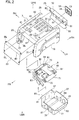
Fig. 2] Fig. 2 is an exploded perspective view showing an attachment member, a heat-generating electric component, a junction box, and a housing according to the embodiment of the present invention. - [
Fig. 3] Fig. 3 is a plan view showing the attachment member and a heater duct according to the embodiment of the present invention. - [
Fig. 4] Fig. 4 is a cross-sectional view taken along line A-A inFig. 1 . - [
Fig. 5] Fig. 5 is a cross-sectional view taken along line B-B inFig. 1 . - [
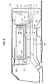
Fig. 6] Fig. 6 is an enlarged cross-sectional view of a main section inFig. 5 and shows the flow of discharged air. - [
Fig. 7] Fig. 7 is a schematic view showing how the attachment member is deformed when a side collision load is inputted into a lateral side of the vehicle body. - An embodiment of the present invention will now be described in detail with the drawings. Note that FR, RR, UPR, LWR, RH, and LH in the drawings represent the front side, rear side, upper side, lower side, right side, and left side of a vehicle, respectively.
- As shown in
Fig. 1 , front seat assemblies inside a cabin are formed by adriver seat assembly 1 disposed on the right side and apassenger seat assembly 3 disposed on the left side. Anattachment member 7 provided with a heat-generatingelectric component 9 therein is arranged on the upper side of afloor surface 5. Aseat cushion 11 as a constituent component of aseat 2 of thedriver seat assembly 1 is arranged above thisattachment member 7. Also, aninterior power socket 13 andearth 15 are disposed at a center portion, in the widthwise direction, of aprotector 25 covering the rear side of theattachment member 7. Acover 17, which is openable and closable, is attached to theinterior power socket 13. At the time of using theinterior power socket 13, thecover 17 is opened downward to expose theinterior power socket 13. Thus, theinterior power socket 13 is disposed on the rear side (back side) of a space under thefront seat 2. - As shown in
Fig. 2 , theattachment member 7 according to this embodiment includes: a pair of, or two (multiple), left and rightvertical walls 19 standing upward from the floor surface 5 (seeFig. 1 ) of the automobile and separated from each other by a predetermined distance in the vehicle widthwise direction; anupper wall 21 coupling upper portions of the pair ofvertical walls 19 to each other; afront cover 23 covering an opening defined by front portions of thevertical walls 19 and theupper wall 21; and theprotector 25 covering an opening defined by rear portions of thevertical walls 19 and theupper wall 21. - Each
vertical wall 19 extends in the vehicle front-rear direction. At the lower end of thevertical wall 19, alower flange 27 is formed which is bent and extends inward in the widthwise direction, and thelower flange 27 is fastened to thefloor surface 5 of the vehicle with bolts BL. Moreover, at the upper end of thevertical wall 19, anupper flange 29 is formed which is bent and extends inward in the widthwise direction, and the opposite ends of theupper wall 21 in the widthwise direction are joined to theupper flanges 29 of thevertical walls 19. Thus, the upper ends of the pair of left and rightvertical walls 19 are coupled by theupper wall 21, which extends in the vehicle widthwise direction. In addition, at a lower portion of afront end 20 of eachvertical wall 19, atongue piece 31 is provided which extends inward in the widthwise direction. - The
upper wall 21 is formed to be rigid by multiple embossedportions 33 recessed downward and is provided with multiple attachment holes for attaching the heat-generatingelectric component 9, ajunction box 35, and ahousing 37 to theupper wall 21, as will be described later. These attachment holes are designated as afirst attachment hole 41, asecond attachment hole 42, athird attachment hole 43, afourth attachment hole 44, afifth attachment hole 45, and asixth attachment hole 46 in this order from the right to the left in the vehicle widthwise direction. The third to sixth attachment holes are bored at the bottom surfaces of some of the embossedportions 33. Note that afront edge portion 47 of theupper wall 21 is bent and extends diagonally downward toward the front side of the vehicle. - Moreover, the
front cover 23 is bent and extends diagonally upward at itsupper end portion 49 and is fastened to thefront edge portion 47 of theupper wall 21 and thetongue pieces 31 of thevertical walls 19 with bolts BL. - Also, the
protector 25 is formed in an angular U-shape in a side view and is formed by: avertical surface 51 disposed as a center portion in the vertical direction; anupper flange 53 bent and extending forward from the upper end of thevertical surface 51; and anextension portion 55 bent and extending forward from the lower end of thevertical surface 51. Theprotector 25 is fixed to theupper wall 21 by fastening theupper flange 53 of theprotector 25 to arear edge portion 57 of theupper wall 21 with bolts BL. In addition, theinterior power socket 13 and theearth 15 are provided on a rectangularpower socket cover 59. Here, arectangular opening 61 is formed in the center of thevertical surface 51 of theprotector 25, and thepower socket cover 59 is mounted to theprotector 25 in such a way as to close this opening 61. - Meanwhile, the heat-generating
electric component 9, thejunction box 35, and thehousing 37 are attached to the lower side of theupper wall 21 of theattachment member 7. - The heat-generating
electric component 9 is designated particularly as an inverter and a voltage converter in this embodiment. However, the heat-generatingelectric component 9 may be only an inverter or other various types of electric components that generate heat when power is applied thereto. Multiple roundair inlet holes 65 are bored in afront surface 63 of the heat-generatingelectric component 9 while multiple roundair outlet holes 69 are formed in arear surface 67 of the heat-generatingelectric component 9, theair outlet holes 69 communicating with the inside of the heat-generatingelectric component 9. Anattachment bracket 73 is provided at the rear upper end of eachside portion 71 of the heat-generatingelectric component 9 while a pair of left and right upwardly protrudingscrews 75 are provided at the front end of the heat-generatingelectric component 9. Thejunction box 35 is disposed on the right side of the vehicle relative to the heat-generatingelectric component 9. Thehousing 37 is formed in a lid shape open at the top and is formed by abottom surface 77, afront surface 79, arear surface 81, andside surfaces 83. Moreover, at the upper end of eachside surface 83, anattachment flange 85 is formed which is bent and extends outward in the widthwise direction, and thehousing 37 is fixed to theattachment member 7 by fastening theattachment flange 85 to the lower side of theupper wall 21 with bolts BL. Thehousing 37 surrounds these heat-generatingelectric component 9 andjunction box 35 in such a way as to cover them from below. Meanwhile, rectangularair inlet holes 87 are bored in thefront surface 79 of thehousing 37, and rectangularair outlet holes 89 are formed in therear surface 81 of thehousing 37. Also, current converted by the heat-generatingelectric component 9 can be taken out inside the cabin through theinterior power socket 13. - Description will now be given of spots where the heat-generating
electric component 9, thejunction box 35, and thehousing 37 are fixed to theattachment member 7. - A
fifth insertion hole 95 formed in eachattachment bracket 73 of the heat-generatingelectric component 9 is disposed to coincide with the correspondingfifth attachment hole 45 in theupper wall 21 of theattachment member 7. Moreover, eachscrew 75 at the front end of the heat-generatingelectric component 9 is disposed to coincide with the correspondingsixth attachment hole 46 in theupper wall 21. Via fastening with the bolts BL and thescrews 75 in this state, the heat-generatingelectric component 9 is fixed to theupper wall 21 of theattachment member 7. As a result, the heat-generatingelectric component 9 is disposed away from thefloor surface 5 in the vertical direction. - Also, a
third insertion hole 93 in thejunction box 35 is disposed to coincide with thethird attachment hole 43 in theupper wall 21 of theattachment member 7. Moreover, afourth insertion hole 94 in thejunction box 35 is disposed to coincide with thefourth attachment hole 44 in theupper wall 21. By inserting and fastening bolts in the attachment holes and the insertion holes in this state, thejunction box 35 is fixed to theupper wall 21 of theattachment member 7. - A
first insertion hole 91 in eachattachment flange 85 of thehousing 37 is disposed to coincide with the correspondingfirst attachment hole 41 in theupper wall 21 of theattachment member 7. Moreover, asecond insertion hole 92 in eachattachment flange 85 of thehousing 37 is disposed to coincide with the correspondingsecond attachment hole 42 in theupper wall 21. By inserting and fastening bolts in the attachment holes and the insertion holes in this state, thehousing 37 is fixed to theupper wall 21 of theattachment member 7. - To summarize the above, in the procedure of assembling the
attachment member 7 according to this embodiment, firstly, thevertical walls 19 are joined to theupper wall 21 by welding or the like, and the heat-generatingelectric component 9 and thejunction box 35 are then fixed to the lower side of theupper wall 21. Thereafter, thehousing 37 is attached to theupper wall 21 in such a way as to cover the heat-generatingelectric component 9 and thejunction box 35, and thelower flanges 27 of thevertical walls 19 are then fastened to thefloor surface 5. Lastly, thefront cover 23 and theprotector 25 are fixed to thevertical walls 19 and theupper wall 21. - As shown in
Fig. 3 , aninstrument panel 99 is arranged along the vehicle widthwise direction at a front section of the cabin, and anair conditioning unit 101 is arranged behind theinstrument panel 99. Anend portion 105 of a heater duct 103 (duct) is connected to thisair conditioning unit 101. Behind theinstrument panel 99, theheater duct 103 extends downwardly from theair conditioning unit 101 and is then bent toward the right side of the vehicle and extends in the vehicle widthwise direction. Theheater duct 103 is thereafter bent toward the rear side of the vehicle and extends out of theinstrument panel 99 and then to a lower portion of theattachment member 7 on the right side of the vehicle. Theheater duct 103 is a duct of a hollow shape through which temperature adjustment air that is warm flows. Note that aharness 107 extending from theattachment member 7 is connected to theair conditioning unit 101. - As shown in
Fig. 4 , aside sill 111 extending in the vehicle front-rear direction is provided on a lateral side of a floor panel 109 (floor surface 5). Amember 113 extending in the vehicle front-rear direction is joined to the lower surface of a portion of thefloor panel 109 which coincides with a center portion of theseat cushion 11 in the vehicle widthwise direction. Moreover, thelower flanges 27 of thevertical walls 19 of theattachment member 7 are fastened to thefloor panel 109 with the bolts BL, thereby fixing theattachment member 7 to thefloor surface 5. Seat slide rails 115 are fixed to the tops of thevertical walls 19 of theattachment member 7. Thus, theattachment member 7 is arranged under theseat cushion 11, which is a constituent component of theseat 2 of the automobile. The seat slide rails 115 extend in the vehicle front-rear direction and theseat 2 is held slidably in the front-rear direction. Hence, theattachment member 7 remains fixed to thefloor surface 5 even when theseat 2 is slid in the front-rear direction. - As shown in
Figs. 5 and6 , the heat-generatingelectric component 9 and the heater duct 103 (duct) are arranged between theseat cushion 11 of theseat 2 and thefloor surface 5. Specifically, theattachment member 7 is fixed on thefloor surface 5, and theseat 2 is arranged above theattachment member 7. Inside theattachment member 7, there are theheater duct 103 which is disposed above thefloor surface 5 and the heat-generatingelectric component 9 which is disposed above theheater duct 103. A rear section of theheater duct 103 includes: abent portion 117 bent near the front end of thehousing 37 and extending diagonally upward toward the rear side; and arear end portion 119 extending from the rear end of thebent portion 117 toward the rear side of the vehicle along the floor surface 5 (substantially in parallel with the floor surface 5). Also, the tip of therear end portion 119 is formed as anexit 121 fortemperature adjustment air 129. - Here, since a
main part 123 inside the heat-generatingelectric component 9 generates heat when power is applied thereto, a cooling mechanism configured to cool themain part 123 is provided. This cooling mechanism is formed by the air inlet holes 65 in thefront surface 63 of the heat-generatingelectric component 9, anair intake fan 125 inside the heat-generatingelectric component 9, and the air outlet holes 69 in therear surface 67 of the heat-generatingelectric component 9. Thus, by rotating theair intake fan 125, ambient air is taken in from the air inlet holes 65 in thefront surface 63 and is caused to exchange heat with themain part 123 inside the heat-generatingelectric component 9. The air heated by the heat exchange is then discharged from the air outlet holes 69 in therear surface 67. As a result, themain part 123 of the heat-generatingelectric component 9 is cooled. - Meanwhile, the air outlet holes 69, through which the air on the inside of the heat-generating
electric component 9 is discharged to cool the inside, are formed in therear surface 67 of the heat-generatingelectric component 9, and also the air outlet holes 89, through which the air on the inside of thehousing 37 is discharged outward to cool the inside of thehousing 37, are formed in therear surface 81 of thehousing 37 as well. The air outlet holes 89 of thehousing 37 are disposed rearward of the air outlet holes 69 of the heat-generatingelectric component 9, and theexit 121 of theheater duct 103 is disposed rearward of the air outlet holes 89 of thehousing 37. Note that theexit 121 of theheater duct 103 is disposed near the air outlet holes 69 of the heat-generatingelectric component 9 and the air outlet holes 89 of thehousing 37. In addition, theair intake fan 125 is arranged inside the heat-generatingelectric component 9 in front of themain part 123. Also, theprotector 25 is disposed to face the rear side of the heat-generatingelectric component 9. Theextension portion 55 of thisprotector 25 extends diagonally forward toward theexit 121 of theheater duct 103. In other words, theextension portion 55 of theprotector 25 is inclined to extend slightly downward toward the front side from the lower end of thevertical surface 51 of theprotector 25. Moreover, theinterior power socket 13, which is attached to theprotector 25, is connected to the heat-generatingelectric component 9 by aharness 127. - Using
Fig. 6 , description will now be given of the flow of cooling air flowing through the heat-generatingelectric component 9 and the flow of thetemperature adjustment air 129 discharged from theexit 121 of theheater duct 103. - Since the
main part 123 arranged inside the heat-generatingelectric component 9 generates heat when power is applied thereto, it needs to be cooled with cooling air. - When the
air intake fan 125 of the heat-generatingelectric component 9 is actuated,ambient air 135 is taken into the heat-generatingelectric component 9 from the air inlet holes 87 of thehousing 37 through the air inlet holes 65 of the heat-generatingelectric component 9. Theair 135 then flows toward the rear side of the vehicle, thereby cooling themain part 123. Theair 135 is then discharged to the rear side of thehousing 37 from the air outlet holes 69 of the heat-generatingelectric component 9 through the air outlet holes 89 of thehousing 37. - On the other hand, the
temperature adjustment air 129 is blowing rearward out of theexit 121 of theheater duct 103. For this reason, an exit-side space 131 surrounded by therear surface 81 of thehousing 37 and theupper flange 53, thevertical surface 51, and theextension portion 55 of theprotector 25 is at negative pressure lower than the atmospheric pressure. - Hence, discharged
air 133 discharged from the air outlet holes 89 of thehousing 37 flows downward through the exit-side space 131, which is at the negative pressure, is drawn to theexit 121 of theheater duct 103, and blown rearward along with thetemperature adjustment air 129 from theexit 121. - Note that the
interior power socket 13 is disposed rearward of and around the air outlet holes 69 of the heat-generatingelectric component 9, and theexit 121 of theheater duct 103 is disposed below the air outlet holes 69 of the heat-generatingelectric component 9. - Using
Fig. 7 , description will now be given of how theattachment member 7 is deformed in a side collision of the vehicle. - As mentioned above, the lower ends of the
vertical walls 19 of theattachment member 7 are fixed to thefloor surface 5. - Thus, as shown in
Fig. 7 , when a side collision load F is inputted into theattachment member 7 from the right side of the vehicle, thevertical walls 19 are deformed such that the upper ends are moved toward the left side of the vehicle, which is the inner side in the vehicle widthwise direction, with the lower ends remaining fixed to thefloor surface 5. - Specifically, as shown by two-dot chain lines, before the side collision load F is inputted, the
attachment member 7 and thefloor surface 5 define a horizontally long rectangular shape. On the other hand, as shown by solid lines, when the side collision load is inputted, both left and rightvertical walls attachment member 7 and thefloor surface 5 define a parallelogram shape after the deformation. - Description will now be given of operations and effects by this embodiment.
- (1) In the structure for arranging the heat-generating
electric component 9 in an automobile according to this embodiment, the heat-generatingelectric component 9 and the heater duct 103 (duct), which extends from theair conditioning unit 101, are disposed between theseat 2 and thefloor surface 5 of the automobile. In the heat-generatingelectric component 9, the air outlet holes 69 are formed, through which the air on the inside of the heat-generatingelectric component 9 is discharged to cool the inside, and theexit 121 of theheater duct 103 is disposed near the air outlet holes 69 of the heat-generatingelectric component 9. - In this way, the air-conditioning air discharged from the
exit 121 of theheater duct 103 reduces the air pressure in the vicinity of the air outlet holes 69 of the heat-generatingelectric component 9 to negative pressure, so that the dischargedair 133 from the heat-generatingelectric component 9 is drawn to theexit 121 of theheater duct 103. Thus, the amount of the dischargedair 133 is increased. Accordingly, the heat-generatingelectric component 9 can be cooled efficiently. - (2) The air outlet holes 69 of the heat-generating
electric component 9 are formed in therear surface 67 of the heat-generatingelectric component 9, and theexit 121 of theheater duct 103 is disposed rearward of the air outlet holes 69 of the heat-generatingelectric component 9. - In this way, even when the air-conditioning air from the
heater duct 103 istemperature adjustment air 129 that is warm, that warmtemperature adjustment air 129 can be prevented from directly contacting the heat-generatingelectric component 9. Also, with the airflow from theheater duct 103 formed rearward of the air outlet holes 69, the heat inside the heat-generatingelectric component 9 can be prevented from returning again to the inside of the heat-generatingelectric component 9. Thus, the dischargedair 133 from the heat-generatingelectric component 9 is drawn to theexit 121 of theheater duct 103, thereby increasing the effect of increasing the amount of the dischargedair 133. - Note that if the
exit 121 of theheater duct 103 is disposed forward of the air outlet holes 69, the dischargedair 133 which has been discharged to the outside of the heat-generatingelectric component 9 may possibly return again to the inside of the heat-generatingelectric component 9. - (3) The duct is the
heater duct 103 through which thetemperature adjustment air 129 that is warm is caused to flow. - In this way, the hot discharged
air 133 from the heat-generatingelectric component 9 joins and flows together with the warmtemperature adjustment air 129 discharged from theheater duct 103, thereby enhancing the performance of heating inside the cabin. - (4) The seat is the
seat 2 of the front seat assembly, and theprotector 25 is arranged rearward of the heat-generatingelectric component 9, and theprotector 25 is provided with theextension portion 55, which extends toward theexit 121 of theheater duct 103. - The
extension portion 55 can prevents the air-conditioning air from blowing into the heat-generatingelectric component 9 side after being discharged from theexit 121 of theheater duct 103, which ensures that the air-conditioning air is discharged without being disturbed. Hence, the hot dischargedair 133 from the air outlet holes 69 of the heat-generatingelectric component 9 can be efficiently drawn into the airflow from theheater duct 103 to cool the heat-generatingelectric component 9. - (5) The heat-generating
electric component 9 is disposed above theheater duct 103. - In this way, the
heater duct 103 is disposed between thefloor surface 5 and the heat-generatingelectric component 9. Hence, when theseat 2 is sunk downward in the event of a collision of the vehicle or the like, the hollow duct interposed between thefloor surface 5 and the heat-generatingelectric component 9 can absorb part of the energy of the collision and reduce the load to be inputted to the heat-generatingelectric component 9. - (6) The
interior power socket 13 is disposed rearward of and around the air outlet holes 69 of the heat-generatingelectric component 9, and theexit 121 of theheater duct 103 is disposed below the air outlet holes 69 of the heat-generatingelectric component 9. - This can reduce the hot discharged
air 133 from the heat-generatingelectric component 9 that contacts theinterior power socket 13. Specifically, the air outlet holes 69 of the heat-generatingelectric component 9 are disposed at substantially the same height level as theinterior power socket 13. For this reason, the hot dischargedair 133 from the air outlet holes 69 tries to flow to theinterior power socket 13. However, the airflow directed rearward from theexit 121 of theheater duct 103 downwardly draws the dischargedair 133 from the heat-generatingelectric component 9 and causes it to flow rearward. This can reduce the hot dischargedair 133 that contacts theinterior power socket 13, which is disposed rearward of the heat-generatingelectric component 9, after being discharged from the heat-generatingelectric component 9. - (7) The heat-generating
electric component 9, thehousing 37, which surrounds the outer side of the heat-generatingelectric component 9, and theheater duct 103, which extends from theair conditioning unit 101, are disposed between theseat 2 and thefloor surface 5 of the automobile. Moreover, the air outlet holes 89, through which the air on the inside of thehousing 37 is discharged outward to cool the inside of thehousing 37, are formed in thehousing 37, and theexit 121 of theheater duct 103 is disposed near the air outlet holes 89 of thehousing 37. - Since the inside of the
housing 37 is a closed space, the hot dischargedair 133 from the heat-generatingelectric component 9 stays inside thehousing 37. Here, the air-conditioning air discharged from theexit 121 of theheater duct 103 reduces the air pressure near the air outlet holes 89 of thehousing 37 to negative pressure. The negative pressure draws the dischargedair 133 from the air outlet holes 89 of thehousing 37 to theexit 121 of theheater duct 103, thereby increasing the amount of the dischargedair 133. Accordingly, the heat-generatingelectric component 9 can be cooled efficiently. - (8) Inside the
attachment member 7, theheater duct 103 is bent to be above thefloor surface 5, and theexit 121 of theheater duct 103 is therefore disposed above thefloor surface 5. This can reduce dust, dirt, and the like on thefloor surface 5 blown up by the airflow from theexit 121 of theheater duct 103. Moreover, a space to dispose other members can be left under theheater duct 103. Hence, the internal space of theattachment member 7 can be effectively utilized. - Note that the present invention is not limited to the embodiment described above, and various changes and modifications can be made. For example, while the
housing 37, which surrounds the heat-generatingelectric component 9, is provided in the embodiment, thishousing 37 may be omitted. Also, while the embodiment has been described by taking theseat 2 of thedriver seat assembly 1, which is a front seat assembly, as an example, theattachment member 7 and other parts may be provided, for example, under the seat of a middle seat assembly in the front-rear direction among three rows of seat assemblies aligned side by side in the front-rear direction. Further, instead of theheater duct 103, a duct through which normal air-conditioning air is caused to flow may be employed. - Note that the entire content of
Japanese Patent Application No. 2013-079353 (filed on April 5, 2013 - According to the structure for arranging a heat-generating electric component in an automobile according to the present invention, the air-conditioning air discharged from the exit of the duct reduces the air pressure near the air outlet holes of the heat-generating electric component to negative pressure, thereby drawing the discharged air from the heat-generating electric component to the exit of the duct. Thus, the amount of the discharged air from the heat-generating electric component is increased. Accordingly, the heat-generating electric component can be cooled efficiently.
-
- 2
- seat
- 5
- floor surface
- 9
- heat-generating electric component
- 55
- extension portion
- 67
- rear surface
- 69
- air outlet hole
- 101
- air conditioning unit
- 103
- heater duct (duct)
- 121
- exit
- 129
- temperature adjustment air
Claims (7)
- A structure for arranging a heat-generating electric component in an automobile, comprising
a heat-generating electric component; and
a duct extending from an air conditioning unit, wherein
the heat-generating electric component and the duct are disposed between a seat and a floor surface of an automobile,
in the heat-generating electric component, an air outlet hole is formed through which air on an inside of the heat-generating electric component is discharged to cool the inside, and
an exit of the duct is disposed near the air outlet hole of the heat-generating electric component. - The structure for arranging a heat-generating electric component in an automobile according to claim 1, wherein
the air outlet hole of the heat-generating electric component is formed in a rear surface of the heat-generating electric component, and
the exit of the duct is disposed rearward of the air outlet hole of the heat-generating electric component. - The structure for arranging a heat-generating electric component in an automobile according to claim 1 or 2, wherein the duct is a heater duct through which temperature adjustment air that is warm is caused to flow.
- The structure for arranging a heat-generating electric component in an automobile according to any one of claims 1 to 3, wherein
the seat is a seat of a front seat assembly, and
a protector is arranged rearward of the heat-generating electric component, and the protector is provided with an extension portion extending toward the exit of the duct. - The structure for arranging a heat-generating electric component in an automobile according to any one of claims 1 to 4, wherein the heat-generating electric component is disposed above the duct.
- The structure for arranging a heat-generating electric component in an automobile according to any one of claims 1 to 5, wherein
an interior power socket is disposed rearward of and around the air outlet hole of the heat-generating electric component, and
the exit of the duct is disposed below the air outlet hole of the heat-generating electric component. - A structure for arranging a heat-generating electric component in an automobile, comprising:a heat-generating electric component;a housing surrounding an outer side of the heat-generating electric component; anda duct extending from an air conditioning unit, whereinthe heat-generating electric component, the housing, and the duct are disposed between a seat and a floor surface of an automobile,in the housing, an air outlet hole is formed through which air on an inside of the housing is discharged outward to cool the inside of the housing, andan exit of the duct is disposed near the air outlet hole of the housing.
Applications Claiming Priority (2)
| Application Number | Priority Date | Filing Date | Title |
|---|---|---|---|
| JP2013079353 | 2013-04-05 | ||
| PCT/JP2014/057745 WO2014162892A1 (en) | 2013-04-05 | 2014-03-20 | Structure for installing heat generating electric component in automobile |
Publications (3)
| Publication Number | Publication Date |
|---|---|
| EP2982544A1 true EP2982544A1 (en) | 2016-02-10 |
| EP2982544A4 EP2982544A4 (en) | 2016-04-20 |
| EP2982544B1 EP2982544B1 (en) | 2017-09-27 |
Family
ID=51658192
Family Applications (1)
| Application Number | Title | Priority Date | Filing Date |
|---|---|---|---|
| EP14778929.1A Not-in-force EP2982544B1 (en) | 2013-04-05 | 2014-03-20 | Structure for installing heat generating electric component in automobile |
Country Status (5)
| Country | Link |
|---|---|
| US (1) | US10160286B2 (en) |
| EP (1) | EP2982544B1 (en) |
| JP (1) | JP6107938B2 (en) |
| CN (1) | CN105050864B (en) |
| WO (1) | WO2014162892A1 (en) |
Cited By (1)
| Publication number | Priority date | Publication date | Assignee | Title |
|---|---|---|---|---|
| EP3650280A1 (en) * | 2018-11-12 | 2020-05-13 | Toyota Jidosha Kabushiki Kaisha | Autonomous driving device module mounting structure and autonomous driving electric vehicle |
Families Citing this family (12)
| Publication number | Priority date | Publication date | Assignee | Title |
|---|---|---|---|---|
| JP6341215B2 (en) * | 2016-01-19 | 2018-06-13 | マツダ株式会社 | Auxiliary equipment arrangement structure of automobile |
| JP6302948B2 (en) * | 2016-03-17 | 2018-03-28 | 本田技研工業株式会社 | vehicle |
| JP6515073B2 (en) * | 2016-08-24 | 2019-05-15 | 本田技研工業株式会社 | Power supply unit case structure |
| JP6442451B2 (en) * | 2016-09-02 | 2018-12-19 | 本田技研工業株式会社 | Case structure of power equipment unit |
| US10807437B2 (en) | 2017-09-26 | 2020-10-20 | Emerson Climate Technologies, Inc. | Evaporator freeze prevention systems and methods |
| US11240941B2 (en) * | 2018-09-12 | 2022-02-01 | Toyota Motor Engineering & Manufacturing North America, Inc. | Autonomous vehicle lidar cooling system |
| US11596075B2 (en) | 2020-05-12 | 2023-02-28 | Nissan North America, Inc. | Inverter assembly |
| JP2022060028A (en) * | 2020-10-02 | 2022-04-14 | トヨタ自動車株式会社 | Motor vehicle |
| JP7826710B2 (en) * | 2022-01-26 | 2026-03-10 | 日産自動車株式会社 | Exhaust heat duct structure |
| JP7632390B2 (en) * | 2022-05-30 | 2025-02-19 | トヨタ自動車株式会社 | vehicle |
| CN119654247A (en) * | 2022-08-26 | 2025-03-18 | 日产自动车株式会社 | High voltage device vehicle-mounted structure |
| JP7585372B2 (en) * | 2023-03-13 | 2024-11-18 | 本田技研工業株式会社 | vehicle |
Family Cites Families (28)
| Publication number | Priority date | Publication date | Assignee | Title |
|---|---|---|---|---|
| JPS5836575Y2 (en) | 1979-11-06 | 1983-08-17 | カルソニックカンセイ株式会社 | Automotive heating system |
| JPH01160755A (en) | 1987-12-16 | 1989-06-23 | Roode Rannaa Kk | Automobile |
| US6152096A (en) * | 1999-07-06 | 2000-11-28 | Visteon Global Technologies, Inc. | Storage battery protection by engine air intake system |
| US6902020B2 (en) * | 2002-07-29 | 2005-06-07 | Daimlerchrysler Corporation | Interior vehicle battery system and method |
| US7051825B2 (en) * | 2003-05-21 | 2006-05-30 | Honda Motor Co., Ltd. | Structure for installing high-voltage equipment component to vehicle |
| JP3784813B2 (en) | 2003-11-26 | 2006-06-14 | 本田技研工業株式会社 | High-voltage cooling device for vehicle motor and hybrid vehicle |
| JP4503345B2 (en) | 2004-04-22 | 2010-07-14 | 本田技研工業株式会社 | Cooling structure for vehicle battery or high-voltage components |
| DE102005013567A1 (en) * | 2005-03-23 | 2006-09-28 | Siemens Ag | Component cooling arrangement for vehicle, has air suction element to draw cooling air away from component after cooling air flow through surface of component |
| JP4673692B2 (en) * | 2005-07-19 | 2011-04-20 | 本田技研工業株式会社 | Cooling structure for electrical equipment in vehicles |
| JP4274165B2 (en) * | 2005-10-06 | 2009-06-03 | トヨタ自動車株式会社 | Cooling device for on-vehicle equipment |
| JP5019309B2 (en) * | 2006-09-13 | 2012-09-05 | 富士重工業株式会社 | In-vehicle electronic device cooling structure |
| US8127876B2 (en) * | 2006-10-26 | 2012-03-06 | Deere & Company | Cooling enclosure for electronic motor control components |
| JP2009106112A (en) * | 2007-10-24 | 2009-05-14 | Toshiba Corp | On-vehicle power generation system |
| US8455133B2 (en) * | 2008-01-29 | 2013-06-04 | Cobasys, Llc | Battery pack |
| JP4319239B2 (en) * | 2008-02-07 | 2009-08-26 | 本田技研工業株式会社 | Hybrid vehicle |
| DE102009000204A1 (en) * | 2009-01-14 | 2010-07-15 | Robert Bosch Gmbh | Electric drive and heating for a vehicle, and method for heating a vehicle |
| JP5336905B2 (en) * | 2009-03-31 | 2013-11-06 | 本田技研工業株式会社 | Temperature control device |
| US8950467B2 (en) * | 2009-06-10 | 2015-02-10 | Halla Visteon Climate Control Corporation | Seat-air conditioning system for automotive vehicles |
| FR2949391B1 (en) * | 2009-08-31 | 2012-12-14 | Peugeot Citroen Automobiles Sa | MOTOR VEHICLE COMPRISING A COOLING CIRCUIT OF AN ELECTRIC POWER SUPPLY MODULE |
| JP5024353B2 (en) * | 2009-10-29 | 2012-09-12 | トヨタ自動車株式会社 | Cooling system for electrical equipment |
| JP2011220014A (en) | 2010-04-12 | 2011-11-04 | Kobelco Contstruction Machinery Ltd | Electric work machine |
| JP5459131B2 (en) * | 2010-07-26 | 2014-04-02 | スズキ株式会社 | Air-cooled fuel cell vehicle |
| JP5473954B2 (en) * | 2011-01-14 | 2014-04-16 | 本田技研工業株式会社 | High-voltage equipment device having cooling structure and vehicle equipped with the same |
| US20130292097A1 (en) | 2011-01-27 | 2013-11-07 | Toyota Jidosha Kabushiki Kaisha | Cooling apparatus |
| FR2972143B1 (en) * | 2011-03-01 | 2013-09-20 | Renault Sa | SYSTEM FOR CONNECTING A POWER BATTERY TO A MOTOR VEHICLE |
| KR101342931B1 (en) * | 2011-03-09 | 2013-12-18 | 한라비스테온공조 주식회사 | Heat pump system for vehicle |
| JP5477322B2 (en) | 2011-04-01 | 2014-04-23 | マツダ株式会社 | Vehicle electrical component arrangement structure |
| JP5810615B2 (en) * | 2011-05-09 | 2015-11-11 | スズキ株式会社 | Protective structure for automotive electrical components |
-
2014
- 2014-03-20 US US14/781,798 patent/US10160286B2/en active Active
- 2014-03-20 JP JP2015509999A patent/JP6107938B2/en not_active Expired - Fee Related
- 2014-03-20 EP EP14778929.1A patent/EP2982544B1/en not_active Not-in-force
- 2014-03-20 WO PCT/JP2014/057745 patent/WO2014162892A1/en not_active Ceased
- 2014-03-20 CN CN201480017912.8A patent/CN105050864B/en not_active Expired - Fee Related
Cited By (1)
| Publication number | Priority date | Publication date | Assignee | Title |
|---|---|---|---|---|
| EP3650280A1 (en) * | 2018-11-12 | 2020-05-13 | Toyota Jidosha Kabushiki Kaisha | Autonomous driving device module mounting structure and autonomous driving electric vehicle |
Also Published As
| Publication number | Publication date |
|---|---|
| CN105050864A (en) | 2015-11-11 |
| EP2982544B1 (en) | 2017-09-27 |
| US10160286B2 (en) | 2018-12-25 |
| JPWO2014162892A1 (en) | 2017-02-16 |
| CN105050864B (en) | 2018-05-18 |
| WO2014162892A1 (en) | 2014-10-09 |
| US20160039263A1 (en) | 2016-02-11 |
| EP2982544A4 (en) | 2016-04-20 |
| JP6107938B2 (en) | 2017-04-05 |
Similar Documents
| Publication | Publication Date | Title |
|---|---|---|
| EP2982544B1 (en) | Structure for installing heat generating electric component in automobile | |
| JP5699222B2 (en) | Wiring protection cover structure for electric vehicles | |
| JP5477322B2 (en) | Vehicle electrical component arrangement structure | |
| JP4363350B2 (en) | Secondary battery cooling structure | |
| JP4774783B2 (en) | Drive battery pack mounting structure | |
| US12059949B2 (en) | Installation structure of electrical component module in vehicle | |
| JP6442450B2 (en) | vehicle | |
| JP5430276B2 (en) | Cooling structure for vehicle battery | |
| JP5672493B2 (en) | Electric vehicle cooling system | |
| JP2009083656A (en) | Electric car | |
| JP2017077790A (en) | vehicle | |
| JP2022038128A (en) | Mounting structure for battery | |
| JP2012214161A (en) | Electric component arrangement structure of vehicle | |
| CN108237867A (en) | The air-conditioning unit installation portion structure of vehicle | |
| JP7552375B2 (en) | Electrical component mounting structure | |
| JP6164068B2 (en) | Vehicle electrical component arrangement structure | |
| WO2014162887A1 (en) | Arrangement structure of electric power converter in automobile | |
| JP6164069B2 (en) | Vehicle electrical component arrangement structure | |
| JP2016084023A (en) | vehicle | |
| JP2021030966A (en) | Exhaust flow path structure | |
| US11596075B2 (en) | Inverter assembly |
Legal Events
| Date | Code | Title | Description |
|---|---|---|---|
| PUAI | Public reference made under article 153(3) epc to a published international application that has entered the european phase |
Free format text: ORIGINAL CODE: 0009012 |
|
| 17P | Request for examination filed |
Effective date: 20151102 |
|
| AK | Designated contracting states |
Kind code of ref document: A1 Designated state(s): AL AT BE BG CH CY CZ DE DK EE ES FI FR GB GR HR HU IE IS IT LI LT LU LV MC MK MT NL NO PL PT RO RS SE SI SK SM TR |
|
| AX | Request for extension of the european patent |
Extension state: BA ME |
|
| A4 | Supplementary search report drawn up and despatched |
Effective date: 20160318 |
|
| RIC1 | Information provided on ipc code assigned before grant |
Ipc: H05K 7/20 20060101ALI20160314BHEP Ipc: B60H 1/00 20060101ALN20160314BHEP Ipc: B60H 1/14 20060101ALI20160314BHEP Ipc: B60H 1/32 20060101ALI20160314BHEP Ipc: B60K 1/00 20060101ALI20160314BHEP Ipc: B60K 11/06 20060101ALI20160314BHEP Ipc: B60R 16/02 20060101AFI20160314BHEP |
|
| DAX | Request for extension of the european patent (deleted) | ||
| STAA | Information on the status of an ep patent application or granted ep patent |
Free format text: STATUS: EXAMINATION IS IN PROGRESS |
|
| 17Q | First examination report despatched |
Effective date: 20170116 |
|
| GRAP | Despatch of communication of intention to grant a patent |
Free format text: ORIGINAL CODE: EPIDOSNIGR1 |
|
| STAA | Information on the status of an ep patent application or granted ep patent |
Free format text: STATUS: GRANT OF PATENT IS INTENDED |
|
| RIC1 | Information provided on ipc code assigned before grant |
Ipc: B60K 1/00 20060101ALI20170622BHEP Ipc: B60H 1/14 20060101ALI20170622BHEP Ipc: B60K 11/06 20060101ALI20170622BHEP Ipc: B60H 1/32 20060101ALI20170622BHEP Ipc: B60H 1/00 20060101ALN20170622BHEP Ipc: H05K 7/20 20060101ALI20170622BHEP Ipc: B60R 16/02 20060101AFI20170622BHEP |
|
| RIC1 | Information provided on ipc code assigned before grant |
Ipc: B60R 16/02 20060101AFI20170626BHEP Ipc: B60H 1/00 20060101ALN20170626BHEP Ipc: B60H 1/32 20060101ALI20170626BHEP Ipc: B60K 1/00 20060101ALI20170626BHEP Ipc: B60H 1/14 20060101ALI20170626BHEP Ipc: H05K 7/20 20060101ALI20170626BHEP Ipc: B60K 11/06 20060101ALI20170626BHEP |
|
| INTG | Intention to grant announced |
Effective date: 20170714 |
|
| GRAS | Grant fee paid |
Free format text: ORIGINAL CODE: EPIDOSNIGR3 |
|
| GRAA | (expected) grant |
Free format text: ORIGINAL CODE: 0009210 |
|
| STAA | Information on the status of an ep patent application or granted ep patent |
Free format text: STATUS: THE PATENT HAS BEEN GRANTED |
|
| AK | Designated contracting states |
Kind code of ref document: B1 Designated state(s): AL AT BE BG CH CY CZ DE DK EE ES FI FR GB GR HR HU IE IS IT LI LT LU LV MC MK MT NL NO PL PT RO RS SE SI SK SM TR |
|
| REG | Reference to a national code |
Ref country code: GB Ref legal event code: FG4D |
|
| REG | Reference to a national code |
Ref country code: CH Ref legal event code: EP |
|
| REG | Reference to a national code |
Ref country code: AT Ref legal event code: REF Ref document number: 931639 Country of ref document: AT Kind code of ref document: T Effective date: 20171015 |
|
| REG | Reference to a national code |
Ref country code: IE Ref legal event code: FG4D |
|
| REG | Reference to a national code |
Ref country code: DE Ref legal event code: R096 Ref document number: 602014015156 Country of ref document: DE |
|
| PG25 | Lapsed in a contracting state [announced via postgrant information from national office to epo] |
Ref country code: HR Free format text: LAPSE BECAUSE OF FAILURE TO SUBMIT A TRANSLATION OF THE DESCRIPTION OR TO PAY THE FEE WITHIN THE PRESCRIBED TIME-LIMIT Effective date: 20170927 Ref country code: NO Free format text: LAPSE BECAUSE OF FAILURE TO SUBMIT A TRANSLATION OF THE DESCRIPTION OR TO PAY THE FEE WITHIN THE PRESCRIBED TIME-LIMIT Effective date: 20171227 Ref country code: LT Free format text: LAPSE BECAUSE OF FAILURE TO SUBMIT A TRANSLATION OF THE DESCRIPTION OR TO PAY THE FEE WITHIN THE PRESCRIBED TIME-LIMIT Effective date: 20170927 Ref country code: SE Free format text: LAPSE BECAUSE OF FAILURE TO SUBMIT A TRANSLATION OF THE DESCRIPTION OR TO PAY THE FEE WITHIN THE PRESCRIBED TIME-LIMIT Effective date: 20170927 Ref country code: FI Free format text: LAPSE BECAUSE OF FAILURE TO SUBMIT A TRANSLATION OF THE DESCRIPTION OR TO PAY THE FEE WITHIN THE PRESCRIBED TIME-LIMIT Effective date: 20170927 |
|
| REG | Reference to a national code |
Ref country code: NL Ref legal event code: MP Effective date: 20170927 |
|
| REG | Reference to a national code |
Ref country code: LT Ref legal event code: MG4D |
|
| REG | Reference to a national code |
Ref country code: AT Ref legal event code: MK05 Ref document number: 931639 Country of ref document: AT Kind code of ref document: T Effective date: 20170927 |
|
| REG | Reference to a national code |
Ref country code: FR Ref legal event code: PLFP Year of fee payment: 5 |
|
| PG25 | Lapsed in a contracting state [announced via postgrant information from national office to epo] |
Ref country code: LV Free format text: LAPSE BECAUSE OF FAILURE TO SUBMIT A TRANSLATION OF THE DESCRIPTION OR TO PAY THE FEE WITHIN THE PRESCRIBED TIME-LIMIT Effective date: 20170927 Ref country code: GR Free format text: LAPSE BECAUSE OF FAILURE TO SUBMIT A TRANSLATION OF THE DESCRIPTION OR TO PAY THE FEE WITHIN THE PRESCRIBED TIME-LIMIT Effective date: 20171228 Ref country code: RS Free format text: LAPSE BECAUSE OF FAILURE TO SUBMIT A TRANSLATION OF THE DESCRIPTION OR TO PAY THE FEE WITHIN THE PRESCRIBED TIME-LIMIT Effective date: 20170927 Ref country code: BG Free format text: LAPSE BECAUSE OF FAILURE TO SUBMIT A TRANSLATION OF THE DESCRIPTION OR TO PAY THE FEE WITHIN THE PRESCRIBED TIME-LIMIT Effective date: 20171227 |
|
| PG25 | Lapsed in a contracting state [announced via postgrant information from national office to epo] |
Ref country code: NL Free format text: LAPSE BECAUSE OF FAILURE TO SUBMIT A TRANSLATION OF THE DESCRIPTION OR TO PAY THE FEE WITHIN THE PRESCRIBED TIME-LIMIT Effective date: 20170927 |
|
| PG25 | Lapsed in a contracting state [announced via postgrant information from national office to epo] |
Ref country code: ES Free format text: LAPSE BECAUSE OF FAILURE TO SUBMIT A TRANSLATION OF THE DESCRIPTION OR TO PAY THE FEE WITHIN THE PRESCRIBED TIME-LIMIT Effective date: 20170927 Ref country code: RO Free format text: LAPSE BECAUSE OF FAILURE TO SUBMIT A TRANSLATION OF THE DESCRIPTION OR TO PAY THE FEE WITHIN THE PRESCRIBED TIME-LIMIT Effective date: 20170927 Ref country code: CZ Free format text: LAPSE BECAUSE OF FAILURE TO SUBMIT A TRANSLATION OF THE DESCRIPTION OR TO PAY THE FEE WITHIN THE PRESCRIBED TIME-LIMIT Effective date: 20170927 |
|
| PG25 | Lapsed in a contracting state [announced via postgrant information from national office to epo] |
Ref country code: SK Free format text: LAPSE BECAUSE OF FAILURE TO SUBMIT A TRANSLATION OF THE DESCRIPTION OR TO PAY THE FEE WITHIN THE PRESCRIBED TIME-LIMIT Effective date: 20170927 Ref country code: EE Free format text: LAPSE BECAUSE OF FAILURE TO SUBMIT A TRANSLATION OF THE DESCRIPTION OR TO PAY THE FEE WITHIN THE PRESCRIBED TIME-LIMIT Effective date: 20170927 Ref country code: IT Free format text: LAPSE BECAUSE OF FAILURE TO SUBMIT A TRANSLATION OF THE DESCRIPTION OR TO PAY THE FEE WITHIN THE PRESCRIBED TIME-LIMIT Effective date: 20170927 Ref country code: IS Free format text: LAPSE BECAUSE OF FAILURE TO SUBMIT A TRANSLATION OF THE DESCRIPTION OR TO PAY THE FEE WITHIN THE PRESCRIBED TIME-LIMIT Effective date: 20180127 Ref country code: AT Free format text: LAPSE BECAUSE OF FAILURE TO SUBMIT A TRANSLATION OF THE DESCRIPTION OR TO PAY THE FEE WITHIN THE PRESCRIBED TIME-LIMIT Effective date: 20170927 Ref country code: SM Free format text: LAPSE BECAUSE OF FAILURE TO SUBMIT A TRANSLATION OF THE DESCRIPTION OR TO PAY THE FEE WITHIN THE PRESCRIBED TIME-LIMIT Effective date: 20170927 |
|
| REG | Reference to a national code |
Ref country code: DE Ref legal event code: R097 Ref document number: 602014015156 Country of ref document: DE |
|
| PG25 | Lapsed in a contracting state [announced via postgrant information from national office to epo] |
Ref country code: DK Free format text: LAPSE BECAUSE OF FAILURE TO SUBMIT A TRANSLATION OF THE DESCRIPTION OR TO PAY THE FEE WITHIN THE PRESCRIBED TIME-LIMIT Effective date: 20170927 |
|
| PLBE | No opposition filed within time limit |
Free format text: ORIGINAL CODE: 0009261 |
|
| STAA | Information on the status of an ep patent application or granted ep patent |
Free format text: STATUS: NO OPPOSITION FILED WITHIN TIME LIMIT |
|
| PG25 | Lapsed in a contracting state [announced via postgrant information from national office to epo] |
Ref country code: PL Free format text: LAPSE BECAUSE OF FAILURE TO SUBMIT A TRANSLATION OF THE DESCRIPTION OR TO PAY THE FEE WITHIN THE PRESCRIBED TIME-LIMIT Effective date: 20170927 |
|
| 26N | No opposition filed |
Effective date: 20180628 |
|
| REG | Reference to a national code |
Ref country code: CH Ref legal event code: PL |
|
| PG25 | Lapsed in a contracting state [announced via postgrant information from national office to epo] |
Ref country code: SI Free format text: LAPSE BECAUSE OF FAILURE TO SUBMIT A TRANSLATION OF THE DESCRIPTION OR TO PAY THE FEE WITHIN THE PRESCRIBED TIME-LIMIT Effective date: 20170927 Ref country code: MC Free format text: LAPSE BECAUSE OF FAILURE TO SUBMIT A TRANSLATION OF THE DESCRIPTION OR TO PAY THE FEE WITHIN THE PRESCRIBED TIME-LIMIT Effective date: 20170927 |
|
| REG | Reference to a national code |
Ref country code: BE Ref legal event code: MM Effective date: 20180331 |
|
| REG | Reference to a national code |
Ref country code: IE Ref legal event code: MM4A |
|
| PG25 | Lapsed in a contracting state [announced via postgrant information from national office to epo] |
Ref country code: LU Free format text: LAPSE BECAUSE OF NON-PAYMENT OF DUE FEES Effective date: 20180320 |
|
| PG25 | Lapsed in a contracting state [announced via postgrant information from national office to epo] |
Ref country code: IE Free format text: LAPSE BECAUSE OF NON-PAYMENT OF DUE FEES Effective date: 20180320 |
|
| PG25 | Lapsed in a contracting state [announced via postgrant information from national office to epo] |
Ref country code: LI Free format text: LAPSE BECAUSE OF NON-PAYMENT OF DUE FEES Effective date: 20180331 Ref country code: CH Free format text: LAPSE BECAUSE OF NON-PAYMENT OF DUE FEES Effective date: 20180331 Ref country code: BE Free format text: LAPSE BECAUSE OF NON-PAYMENT OF DUE FEES Effective date: 20180331 |
|
| PG25 | Lapsed in a contracting state [announced via postgrant information from national office to epo] |
Ref country code: MT Free format text: LAPSE BECAUSE OF NON-PAYMENT OF DUE FEES Effective date: 20180320 |
|
| PG25 | Lapsed in a contracting state [announced via postgrant information from national office to epo] |
Ref country code: TR Free format text: LAPSE BECAUSE OF FAILURE TO SUBMIT A TRANSLATION OF THE DESCRIPTION OR TO PAY THE FEE WITHIN THE PRESCRIBED TIME-LIMIT Effective date: 20170927 |
|
| PG25 | Lapsed in a contracting state [announced via postgrant information from national office to epo] |
Ref country code: PT Free format text: LAPSE BECAUSE OF FAILURE TO SUBMIT A TRANSLATION OF THE DESCRIPTION OR TO PAY THE FEE WITHIN THE PRESCRIBED TIME-LIMIT Effective date: 20170927 |
|
| PG25 | Lapsed in a contracting state [announced via postgrant information from national office to epo] |
Ref country code: MK Free format text: LAPSE BECAUSE OF NON-PAYMENT OF DUE FEES Effective date: 20170927 Ref country code: HU Free format text: LAPSE BECAUSE OF FAILURE TO SUBMIT A TRANSLATION OF THE DESCRIPTION OR TO PAY THE FEE WITHIN THE PRESCRIBED TIME-LIMIT; INVALID AB INITIO Effective date: 20140320 Ref country code: CY Free format text: LAPSE BECAUSE OF FAILURE TO SUBMIT A TRANSLATION OF THE DESCRIPTION OR TO PAY THE FEE WITHIN THE PRESCRIBED TIME-LIMIT Effective date: 20170927 |
|
| PG25 | Lapsed in a contracting state [announced via postgrant information from national office to epo] |
Ref country code: AL Free format text: LAPSE BECAUSE OF FAILURE TO SUBMIT A TRANSLATION OF THE DESCRIPTION OR TO PAY THE FEE WITHIN THE PRESCRIBED TIME-LIMIT Effective date: 20170927 |
|
| PGFP | Annual fee paid to national office [announced via postgrant information from national office to epo] |
Ref country code: GB Payment date: 20220127 Year of fee payment: 9 Ref country code: DE Payment date: 20220126 Year of fee payment: 9 |
|
| PGFP | Annual fee paid to national office [announced via postgrant information from national office to epo] |
Ref country code: FR Payment date: 20220209 Year of fee payment: 9 |
|
| REG | Reference to a national code |
Ref country code: DE Ref legal event code: R119 Ref document number: 602014015156 Country of ref document: DE |
|
| GBPC | Gb: european patent ceased through non-payment of renewal fee |
Effective date: 20230320 |
|
| PG25 | Lapsed in a contracting state [announced via postgrant information from national office to epo] |
Ref country code: GB Free format text: LAPSE BECAUSE OF NON-PAYMENT OF DUE FEES Effective date: 20230320 |
|
| PG25 | Lapsed in a contracting state [announced via postgrant information from national office to epo] |
Ref country code: GB Free format text: LAPSE BECAUSE OF NON-PAYMENT OF DUE FEES Effective date: 20230320 Ref country code: FR Free format text: LAPSE BECAUSE OF NON-PAYMENT OF DUE FEES Effective date: 20230331 Ref country code: DE Free format text: LAPSE BECAUSE OF NON-PAYMENT OF DUE FEES Effective date: 20231003 |