EP2982334A1 - Kupplungsvorrichtung zur Übertragung einer Antriebsbewegung von einem schwingungsübertragenden Handstück auf ein medizinisches, insbesondere zahnärztliches, Werkzeug - Google Patents
Kupplungsvorrichtung zur Übertragung einer Antriebsbewegung von einem schwingungsübertragenden Handstück auf ein medizinisches, insbesondere zahnärztliches, Werkzeug Download PDFInfo
- Publication number
- EP2982334A1 EP2982334A1 EP14180304.9A EP14180304A EP2982334A1 EP 2982334 A1 EP2982334 A1 EP 2982334A1 EP 14180304 A EP14180304 A EP 14180304A EP 2982334 A1 EP2982334 A1 EP 2982334A1
- Authority
- EP
- European Patent Office
- Prior art keywords
- coupling
- projection
- elements
- recess
- coupling elements
- Prior art date
- Legal status (The legal status is an assumption and is not a legal conclusion. Google has not performed a legal analysis and makes no representation as to the accuracy of the status listed.)
- Granted
Links
- 230000008878 coupling Effects 0.000 title claims abstract description 239
- 238000010168 coupling process Methods 0.000 title claims abstract description 239
- 238000005859 coupling reaction Methods 0.000 title claims abstract description 239
- 230000005540 biological transmission Effects 0.000 title claims description 5
- 239000012530 fluid Substances 0.000 claims description 7
- 239000011248 coating agent Substances 0.000 claims description 4
- 238000000576 coating method Methods 0.000 claims description 4
- RTAQQCXQSZGOHL-UHFFFAOYSA-N Titanium Chemical compound [Ti] RTAQQCXQSZGOHL-UHFFFAOYSA-N 0.000 claims description 3
- 229910052719 titanium Inorganic materials 0.000 claims description 3
- 239000010936 titanium Substances 0.000 claims description 3
- 238000000034 method Methods 0.000 claims description 2
- 239000007921 spray Substances 0.000 description 3
- XLYOFNOQVPJJNP-UHFFFAOYSA-N water Substances O XLYOFNOQVPJJNP-UHFFFAOYSA-N 0.000 description 3
- 238000001816 cooling Methods 0.000 description 2
- 238000002604 ultrasonography Methods 0.000 description 2
- 208000006558 Dental Calculus Diseases 0.000 description 1
- 230000015572 biosynthetic process Effects 0.000 description 1
- 230000000295 complement effect Effects 0.000 description 1
- 238000003780 insertion Methods 0.000 description 1
- 230000037431 insertion Effects 0.000 description 1
- 238000002360 preparation method Methods 0.000 description 1
- 238000004381 surface treatment Methods 0.000 description 1
Images
Classifications
-
- A—HUMAN NECESSITIES
- A61—MEDICAL OR VETERINARY SCIENCE; HYGIENE
- A61C—DENTISTRY; APPARATUS OR METHODS FOR ORAL OR DENTAL HYGIENE
- A61C1/00—Dental machines for boring or cutting ; General features of dental machines or apparatus, e.g. hand-piece design
- A61C1/08—Machine parts specially adapted for dentistry
- A61C1/14—Tool-holders, i.e. operating tool holders, e.g. burr holders
- A61C1/148—Non-rotating tool holders, e.g. vibrating, oscillating, nutating
-
- A—HUMAN NECESSITIES
- A61—MEDICAL OR VETERINARY SCIENCE; HYGIENE
- A61C—DENTISTRY; APPARATUS OR METHODS FOR ORAL OR DENTAL HYGIENE
- A61C1/00—Dental machines for boring or cutting ; General features of dental machines or apparatus, e.g. hand-piece design
- A61C1/0061—Air and water supply systems; Valves specially adapted therefor
-
- A—HUMAN NECESSITIES
- A61—MEDICAL OR VETERINARY SCIENCE; HYGIENE
- A61C—DENTISTRY; APPARATUS OR METHODS FOR ORAL OR DENTAL HYGIENE
- A61C1/00—Dental machines for boring or cutting ; General features of dental machines or apparatus, e.g. hand-piece design
- A61C1/02—Dental machines for boring or cutting ; General features of dental machines or apparatus, e.g. hand-piece design characterised by the drive of the dental tools
- A61C1/07—Dental machines for boring or cutting ; General features of dental machines or apparatus, e.g. hand-piece design characterised by the drive of the dental tools with vibratory drive, e.g. ultrasonic
-
- A—HUMAN NECESSITIES
- A61—MEDICAL OR VETERINARY SCIENCE; HYGIENE
- A61C—DENTISTRY; APPARATUS OR METHODS FOR ORAL OR DENTAL HYGIENE
- A61C17/00—Devices for cleaning, polishing, rinsing or drying teeth, teeth cavities or prostheses; Saliva removers; Dental appliances for receiving spittle
- A61C17/16—Power-driven cleaning or polishing devices
- A61C17/20—Power-driven cleaning or polishing devices using ultrasonics
Definitions
- Such coupling devices are used to attach a medical tool, which is designed in particular for removing tartar, to a handpiece which has a vibration source.
- the vibration source is in this case preferably designed as a piezo drive and activates the tool by means of sound or ultrasound.
- Such a coupling device for a medical handpiece and tool is in particular from the EP 2 160 997 A1 known.
- This coupling device for releasably connecting a tool with a medical handpiece comprises a first coupling element provided on the tool and a second coupling element arranged on the handpiece. Both coupling elements are connected by means of a ball-race connection and a contact surface for frictional connection with each other to ensure a tight fit. Only by a firm connection of the tool with the vibration source, a transfer of the vibration energy can be applied to the tool.
- the ball raceway connection in this case has a substantially helically around the longitudinal axis of the coupling device extending guide groove, into which engages a guide element of the other coupling element.
- the contact surface for the frictional connection is preferably formed by a conical contact surface on the tool and a complementary contact surface on the handpiece.
- the first portion for releasably connecting the two coupling elements is formed by a screw connection, preferably by a multi-start thread.
- the second portion preferably has a cylindrical guide surface on the coupling projection and in the coupling recess.
- the coupling device of the first portion for releasably connecting the two coupling elements is arranged in front of the second portion at the front end of the lateral surface of the coupling projection and at the rear end of the lateral surface of the coupling recess.
- the coupling projection has a chamfer at its front end.
- the diameter of the first section on the coupling projection and on the coupling recess is smaller than the diameter of the second section on the coupling projection and on the coupling recess.
- the length of the first section on the coupling projection is preferably smaller than the length of the second section on the coupling recess, so that both coupling elements are guided by the second section to each other and slidable along the common axis of rotation, before the two coupling elements by means of the first portion with each other are connectable.
- the second portion on the coupling projection preferably has a groove-shaped recess.
- At least one of the two coupling elements is at least partially made of titanium. Furthermore, at least one of the two coupling elements is preferably at least partially provided with a wear-resistant coating.
- both coupling elements preferably have a fluid channel, so that a working medium can be fed to the tool. Furthermore, both coupling elements preferably have a stop surface, so that both coupling elements can be clamped together in the axial direction to the common axis of rotation.
- one support region in particular in the form of a polygon, is preferably provided on one of the two coupling elements for applying a tool wrench.
- the present coupling device is characterized by the following advantages.
- both coupling elements of the coupling device which serves both coupling elements to position their common axis of rotation and both coupling elements guided to each other and slidably supported along the common axis of rotation, before the Both coupling elements are releasably connected to each other by means of another section, a faulty connection between the tool and the handpiece is avoided.
- an improper insertion of the external thread into the internal thread is avoided in the formation of the further section as a screw with an internal and external thread by the targeted guidance of the two coupling elements to each other.
- the coupling device according to the invention ensures the user a simple and time-saving attachment of the tool with the handpiece. Repeated application of the first coupling element to the second coupling element in order to preferably insert an external thread of the one coupling element into the internal thread of the second coupling element is no longer necessary.
- the coupling device is not limited to vibration-transmitting handpieces with a vibration source for the preparation of surfaces of teeth. Rather, such coupling devices can also be used with other powered medical handpieces, such as with rotary driven handpieces.
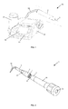
- FIG. 1 a medical, in particular dental, treatment device 29 with a vibration-transmitting handpiece 2 and a medical, in particular dental, tool 3 is shown.
- a vibration source is arranged, which is preferably designed as a piezo drive.
- the tool 3 is preferably detachably connected directly to the drive shaft of the piezo drive by means of the coupling device, so that the tool 3 can be activated by means of sound or ultrasound.
- a supply hose 30 serves to connect the handpiece 2, in particular its drive, with the control unit 31. During operation of the handpiece 2 this and the tool 3 with working media, in particular with electrical energy and spray water to cool the tool to supply.
- the supply hose 30 serves in particular to transmit electrical signals and / or data between the control unit 31 and the handpiece 2.
- the control unit 31 has at least one display 32 and at least one actuating element 33.
- a connectable to the control unit 31 container 34 serves as a source of fluid for the spray water for cooling the handpiece 2 and / or the tool.
- FIG. 2 shows the coupling device 1 according to the invention with a first on a drive shaft 28 of the handpiece 2 and a second provided on the tool 3 coupling element 4, 5.
- the tool 2 shown for surface treatment of teeth comprises a tool shank to which a working head 35 is mounted.
- the working head 35 can have a wide variety of shapes.
- the coupling element 5 is arranged to releasably attach the tool 3 to the other coupling element 4, which is preferably connected to the drive shaft 28 of the handpiece 2.
- the coupling element 4 on the drive axle 28 is in this case preferably designed as a coupling projection 6, which is insertable into a coupling recess 6 of the other coupling element 5.
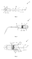
- FIG. 3 is the drive shaft 28 of the handpiece 2 with the coupling projection 4 formed as a coupling element 4 of the coupling device 1 shown.
- the first section 8 on the coupling projection 6 for releasably connecting the two coupling elements 4, 5 is in this embodiment by a Screw connection 13 is formed, which preferably comprises a multi-start thread.
- the drive shaft 28 with the coupling element 4 is preferably made of titanium and has a wear-resistant coating at least in the region of the screw connection.
- the second portion 10 for positioning the two coupling elements 4, 5 to each other is formed by a cylindrical guide surface 15 on the coupling projection 6, which extends along the axis of rotation 12.
- the first section 8 is in this case arranged in front of the second section 10 at the front end 17 of the coupling projection 6.
- the coupling projection 6 has a chamfer 21 at its front end 17.
- the diameter A of the first section 8 is on the coupling projection 6 smaller than the diameter B of the second portion 10 is formed.
- the coupling element 4 On the base surface of the drive shaft 28, from which the coupling projection 6 extends, the coupling element 4 has a stop face 23.
- the abutment surface 23 preferably extends in the radial direction about the coupling projection 6.
- the abutment surfaces 23 are also preferably provided with a wear-resistant coating.
- the corresponding coupling element 5 on the tool 3 also has a stop surface 24, so that both coupling elements 4, 5 by means of the first section 8, 9, in particular by means of the screw 13, 14, in the axial direction to the common axis of rotation 12 are braced together.
- the fluid channel 25 in the drive shaft 28 extends in this embodiment along the common axis of rotation 12 through the coupling element 4, in particular by the coupling projection 6 with the first and second portions 8, 10 to the free end 17 of the coupling projection.
- FIG. 4 The first portion 9 for releasably connecting the two coupling elements 4, 5 is formed by a screw 14 having an internal thread, which is connectable to the external thread 13 on the coupling projection 6 ,
- the first section 9 is arranged here at the rear end 18 of the coupling recess 7.
- the second section 11 in the coupling recess 7 for positioning the two coupling elements 4, 5 to each other is also by a cylindrical Guide surface 16 is formed, which extends in the axial direction to the common axis of rotation 12.
- coupling projection 6 in the coupling recess 7 and the diameter A 'of the first portion 9 is smaller than the diameter B' of the second portion 11 is formed.
- Both coupling elements 4, 5 are so guided by means of the second portion 10, 11 to each other in one another before they can be braced by means of the first portion 8, 9 and the stop surfaces 23, 24 with each other.
- the fluid channel 26 in the tool 3 can be connected to the fluid channel 25 of the drive axle by means of the coupling device 1.
- FIG. 5 is a detailed view of the coupling device 1 shown, in which the tool 3 and the handpiece 2, in particular the first coupling element 4 with the second coupling element 5, is firmly connected.
- This fixed and detachable connection is achieved in that both coupling elements 4, 5 are first positioned to the common axis of rotation 12, in which the coupling projection 6 is inserted with the lateral surface 19 in the coupling recess 7 with the lateral surface 20 until the second portion 10 of the coupling projection 6 is at least partially disposed in the second portion 11 of the coupling recess 7.
- both coupling elements 4, 5 guided to each other and moved along the common axis of rotation 12 until the first portion 8 of the coupling projection 6 engages at least partially in the first portion 9 of the coupling recess 7. Finally, both coupling elements 4, 5 are screwed together by means of the screw connection to the first section 8, 9 and firmly clamped by means of the stop surfaces 23, 24 against each other.
- a constriction 22 in the lateral surface 19 of the coupling projection 6 serves to relieve in the transmission of a drive movement of the handpiece 2 on the tool 3, the first portion 8 on the coupling projection 6, in particular the screw with the inner and outer threads.
- the lengths L, L 'and K, K' of the first section 8, 9 and the second section 10, 11 on the coupling projection 6 and the coupling recess 7 are in this case selected such that both coupling elements 4, 5 guided to each other and along the common axis of rotation 12 are slidable before they are detachably connected to each other by means of the first section 8, 9.
- the length L of the first portion 8 on the coupling projection 6 is smaller than the length K 'of the second portion 11 in the coupling recess 7, so that the second portion 10 of the coupling projection 6 engages in the coupling recess 7, before the first portion 8 of Coupling projection 6 in the first portion 9 of the coupling recess is insertable.
- the length K of the second portion 10 at the Coupling projection 6 and the length K 'of the second portion 11 on the coupling recess 7 are hereby selected to be as large as possible, so that due to the overlap of the two sections 10, 11 an exact positioning and guiding of the two coupling elements 4, 5 can be done to each other.
- the invention is not limited to the described embodiments, but includes all embodiments that apply or include the principle, analogous principle of operation of the invention. Furthermore, all features of all described and illustrated embodiments can be combined.
Landscapes
- Health & Medical Sciences (AREA)
- Oral & Maxillofacial Surgery (AREA)
- Dentistry (AREA)
- Epidemiology (AREA)
- Life Sciences & Earth Sciences (AREA)
- Animal Behavior & Ethology (AREA)
- General Health & Medical Sciences (AREA)
- Public Health (AREA)
- Veterinary Medicine (AREA)
- Engineering & Computer Science (AREA)
- Water Supply & Treatment (AREA)
- Dental Tools And Instruments Or Auxiliary Dental Instruments (AREA)
Abstract
Description
- Die vorliegende Erfindung bezieht sich auf eine Kupplungsvorrichtung zur Übertragung einer Antriebsbewegung und gegebenenfalls eines Arbeitsmediums von einem schwingungsübertragenden Handstück auf ein medizinisches, insbesondere zahnärztliches, Werkzeug nach dem Oberbegriff des Anspruchs 1.
- Derartige Kupplungsvorrichtungen dienen dazu ein medizinisches Werkzeug, welches insbesondere zum Entfernen von Zahnstein ausgebildet ist, an einem Handstück, welches eine Schwingungsquelle aufweist, zu befestigen. Die Schwingungsquelle ist hierbei bevorzugt als Piezoantrieb ausgebildet und aktiviert das Werkzeug mittels Schall oder Ultraschall.
- Eine derartige Kupplungsvorrichtung für ein medizinisches Handstück und Werkzeug ist insbesondere aus der
EP 2 160 997 A1 bekannt. - Diese Kupplungsvorrichtung zur lösbaren Verbindung eines Werkzeuges mit einem medizinischen Handstück umfasst ein erstes am Werkzeug vorgesehenes Kupplungselement und ein zweites am Handstück angeordnetes Kupplungselement. Beide Kupplungselemente werden mittels einer Kugel-Laufbahn Verbindung und einer Anlagefläche zur reibschlüssigen Verbindung miteinander verbunden, um einen festen Sitz zu gewährleisten. Nur durch eine feste Verbindung des Werkzeuges mit der Schwingungsquelle kann eine Übertragung der Schwingungsenergie auf das Werkzeug erfolgen. Die Kugel-Laufbahn Verbindung weist hierbei eine im Wesentlichen wendeiförmig um die Längssachse der Kupplungsvorrichtung verlaufenden Führungsnut auf, in die ein Führungselement des anderen Kupplungselements eingreift. Die Anlagefläche zur reibschlüssigen Verbindung ist bevorzugt durch eine konische Anlagefläche an dem Werkzeug und einer komplementären Anlagefläche an dem Handstück gebildet. Durch das Verdrehen der beiden Kupplungselemente zueinander wird ein Reibschluss zwischen den beiden Anlageflächen hergestellt.
- Der vorliegenden Erfindung liegt die Aufgabe zugrunde, eine Kupplungsvorrichtung zur Übertragung einer Antriebsbewegung von einem schwingungsübertragenden Handstück auf ein medizinisches Werkzeug zu schaffen, welche bei einer vereinfachten Handhabung es insbesondere ermöglicht, eine fehlerhafte Verbindung zwischen dem Werkzeug und dem Handstück zu vermeiden.
- Gemäß einem Ausführungsbeispiel einer Kupplungsvorrichtung zur Übertragung einer Antriebsbewegung und gegebenenfalls eines Arbeitsmediums von einem schwingungsübertragenden Handstück auf ein medizinisches, insbesondere zahnärztliches, Werkzeug mit einem ersten am Handstück und einem zweiten am Werkzeug vorgesehenen Kupplungselement, wobei eines der beiden Kupplungselemente als Kupplungsvorsprung ausgebildet ist, der in eine Kupplungsausnehmung an dem anderen Kupplungselement einsetzbar ist, weist der Kupplungsvorsprung und die Kupplungsausnehmung jeweils einen ersten Abschnitt zur lösbaren Verbindung der beiden Kupplungselemente sowie einen zweiten Abschnitt zur Positionierung der beiden Kupplungselemente zu deren gemeinsamen Drehachse auf, wobei der zweite Abschnitt an dem Kupplungsvorsprung und an der Kupplungsausnehmung derart ausgebildet ist, dass beide Kupplungselemente zueinander geführt und entlang der gemeinsamen Drehachse verschiebbar sind, bevor die beiden Kupplungselemente mittels des ersten Abschnitts lösbar miteinander verbindbar sind.
- Gemäß einem ersten Ausführungsbeispiel der Kupplungsvorrichtung ist der erste Abschnitt zur lösbaren Verbindung beider Kupplungselemente durch eine Schraubverbindung, bevorzugt durch ein mehrgängiges Gewinde, ausgebildet. Zur Positionierung der beiden Kupplungselemente zueinander weist der zweite Abschnitt bevorzugt eine zylindrische Führungsfläche an dem Kupplungsvorsprung und in der Kupplungsausnehmung auf.
- Gemäß einem zweiten Ausführungsbeispiel der Kupplungsvorrichtung ist der erste Abschnitt zur lösbaren Verbindung der beiden Kupplungselemente vor dem zweiten Abschnitt an dem vorderen Ende der Mantelfläche des Kupplungsvorsprungs und an dem hinteren Ende der Mantelfläche der Kupplungsausnehmung angeordnet. Um den ersten Abschnitt des Kupplungsvorsprungs leichter in den korrespondierenden Abschnitt der Kupplungsausnehmung einführen zu können, weist der Kupplungsvorsprung an seinem vorderen Ende eine Fase auf.
- Gemäß einem dritten Ausführungsbeispiel der Kupplungsvorrichtung ist der Durchmesser des ersten Abschnitts an dem Kupplungsvorsprung und an der Kupplungsausnehmung kleiner als der Durchmesser des zweiten Abschnitts an dem Kupplungsvorsprung und an der Kupplungsausnehmung. Des Weiteren ist die Länge des ersten Abschnitts an dem Kupplungsvorsprung bevorzugt kleiner als die Länge des zweiten Abschnitts an der Kupplungsausnehmung, so dass beide Kupplungselemente mittels des zweiten Abschnitts zueinander geführt und entlang der gemeinsamen Drehachse verschiebbar sind, bevor die beiden Kupplungselemente mittels des ersten Abschnitts miteinander verbindbar sind. Um den ersten Abschnitt an dem Kupplungsvorsprung, bei der Übertragung der Antriebsbewegung von dem Handstück auf das Werkzeug, zu entlasten, weist der zweite Abschnitt an dem Kupplungsvorsprung bevorzugt eine rillenförmige Vertiefung auf.
- Gemäß einem vierten Ausführungsbeispiel der Kupplungsvorrichtung ist zumindest eines der beiden Kupplungselemente zumindest teilweise aus Titan gefertigt. Des Weiteren ist bevorzugt zumindest eines der beiden Kupplungselemente zumindest teilweise mit einer verschleißfesten Beschichtung versehen.
- Gemäß allen voranstehenden Ausführungsbeispielen weisen beide Kupplungselemente bevorzugt einen Fluidkanal auf, so dass dem Werkzeug ein Arbeitsmedium zuführbar ist. Des Weiteren weisen beide Kupplungselemente bevorzugt eine Anschlagfläche auf, so dass beide Kupplungselemente in axialer Richtung zur gemeinsamen Drehachse miteinander verspannbar sind.
- Zusätzlich ist gemäß allen voranstehenden Ausführungsbeispielen an einem der beiden Kupplungselemente bevorzugt ein Auflagebereich, insbesondere in Form eines Mehrkants, zum Anlegen eines Werkzeugschlüssels vorgesehen.
- Gemäß einem Ausführungsbeispiel eines Verfahrens zum lösbaren Verbinden eines medizinischen, insbesondere zahnärztlichen, Werkzeugs mit einem schwingungsübertragenden Handstück mittels einer Kupplungsvorrichtung nach einem der vorherstehenden Ausführungsbeispiele, weist dieses folgende Schritte auf:
- Positionieren der beiden Kupplungselemente zu deren gemeinsamen Drehachse durch das Einführen des Kupplungsvorsprungs in die Kupplungsausnehmung bis der zweite Abschnitt des Kupplungsvorsprungs zumindest teilweise in dem zweiten Abschnitt der Kupplungsausnehmung angeordnet ist,
- Verschieben der beiden Kupplungselemente zueinander und entlang deren gemeinsamen Drehachse bis der erste Abschnitt des Kupplungsvorsprungs zumindest teilweise in den ersten Abschnitt der Kupplungsausnehmung greift,
- Verbinden beider Kupplungselemente mittels des ersten Abschnitts an dem Kupplungsvorsprung und an der Kupplungsausnehmung.
- Die vorliegende Kupplungsvorrichtung zeichnet sich durch folgende Vorteile aus.
- Durch die Ausbildung eines Abschnitts an beiden Kupplungselementen der Kupplungsvorrichtung, welcher dazu dient beide Kupplungselemente zu deren gemeinsamen Drehachse zu positionieren und beide Kupplungselemente zueinander geführt und entlang der gemeinsamen Drehachse verschiebbar zu lagern, bevor die beiden Kupplungselemente mittels eines weiteren Abschnitts lösbar miteinander verbindbar sind, wird eine fehlerhafte Verbindung zwischen dem Werkzeug und dem Handstück vermieden. Insbesondere wird bei Ausbildung des weiteren Abschnitts als Schraubverbindung mit einem Innen- und Außengewinde durch die gezielte Führung der beiden Kupplungselemente zueinander ein unsachgemäßes Einsetzen des Außengewindes in das Innengewinde vermieden.
- Des Weiteren gewährleistet die erfindungsgemäße Kupplungsvorrichtung dem Anwender eine einfache und zeitsparende Befestigung des Werkzeuges mit dem Handstück. Mehrmaliges Ansetzen des ersten Kupplungselements an dem zweiten Kupplungselement, um vorzugsweise ein Außengewinde des einen Kupplungselements in das Innengewinde des zweiten Kupplungselements ordnungsgemäß einzusetzen, ist nicht mehr notwendig.
- Im Rahmen der Erfindung versteht es sich selbstverständlich, dass die Kupplungsvorrichtung nicht auf schwingungsübertragende Handstücke mit einer Schwingungsquelle zur Präparation von Oberflächen von Zähnen beschränkt ist. Vielmehr können derartige Kupplungsvorrichtungen auch bei anderen angetriebenen medizinischen Handstücken verwendet werden, wie zum Beispiel bei rotierend angetriebenen Handstücken.
- Nachfolgend wird die Erfindung anhand mehrerer Ausführungsbeispiele und in Verbindung mit den beigefügten Zeichnungen erläutert.
- Dabei zeigt:
-
Figur 1 eine medizinische, insbesondere dentale, Behandlungsvorrichtung mit einem schwingungsübertragenden Handstück und einem daran angeschlossenen medizinischen, insbesondere zahnärztlichen, Werkzeug, -
Figur 2 eine perspektivische Darstellung der Kupplungsvorrichtung mit einem ersten an einer Antriebsachse des Handstücks und einem zweiten am Werkzeug vorgesehenen Kupplungselement, -
Figur 3 einen Querschnitt durch die Antriebsachse des Handstücks mit dem als Kupplungsvorsprung ausgebildeten Kupplungselement der Kupplungsvorrichtung, -
Figur 4 einen Querschnitt durch das medizinische Werkzeug mit dem als Kupplungsausnehmung ausgebildeten Kupplungselement der Kupplungsvorrichtung, -
Figur 5 eine Detailansicht der Kupplungsvorrichtung, bei der das Werkzeug und das Handstück, insbesondere das erste Kupplungselement mit dem zweiten Kupplungselement, verbunden ist; - In
Figur 1 ist eine medizinische, insbesondere dentale, Behandlungsvorrichtung 29 mit einem schwingungsübertragenden Handstück 2 und einem medizinischen, insbesondere zahnärztlichen, Werkzeug 3 gezeigt. In dem Handstück 2 ist eine Schwingungsquelle angeordnet, welche bevorzugt als Piezoantrieb ausgebildet ist. Das Werkzeug 3 ist hierbei bevorzugt mittels der Kupplungsvorrichtung direkt mit der Antriebsachse des Piezoantriebs lösbar verbunden, so dass das Werkzeug 3 mittels Schall oder Ultraschall aktivierbar ist. Ein Versorgungsschlauch 30 dient dazu das Handstück 2, insbesondere dessen Antrieb, mit der Steuereinheit 31 zu verbinden. Während des Betriebs des Handstücks 2 ist dieses sowie das Werkzeug 3 mit Arbeitsmedien, insbesondere mit elektrischer Energie sowie Spraywasser zur Kühlung des Werkzeugs, zu versorgen. Des Weiteren dient der Versorgungsschlauch 30 insbesondere dazu elektrische Signale und/ oder Daten zwischen der Steuereinheit 31 und dem Handstück 2 zu übertragen. Zur Anzeige und Einstellung der Betriebsparameter für das Handstück 2 sowie für das Werkzeugs 3 weist die Steuereinheit 31 zumindest eine Anzeige 32 sowie zumindest ein Betätigungselement 33 auf. Ein an die Steuereinheit 31 anschließbare Behälter 34 dient als Fluidquelle für das Spraywasser zur Kühlung des Handstücks 2 und/ oder des Werkzeugs. - Die
Figur 2 zeigt die erfindungsgemäße Kupplungsvorrichtung 1 mit einem ersten an einer Antriebsachse 28 des Handstücks 2 und einem zweiten am Werkzeug 3 vorgesehenen Kupplungselement 4, 5. Das gezeigte Werkzeug 2 zur Oberflächenbehandlung von Zähnen umfasst einen Werkzeugschaft, an welchen ein Arbeitskopf 35 angebracht ist. Der Arbeitskopf 35 kann unterschiedlichste Formen aufweisen. Auf dem gegenüberliegenden Ende des Schaftes ist das Kupplungselement 5 angeordnet, um das Werkzeug 3 lösbar an dem anderen Kupplungselement 4, welches bevorzugt mit der Antriebsachse 28 des Handstücks 2 verbunden ist, zu befestigen. Das Kupplungselement 4 an der Antriebsachse 28 ist hierbei bevorzugt als Kupplungsvorsprung 6 ausgebildet, welcher in eine Kupplungsausnehmung 6 des anderen Kupplungselements 5 einsetzbar ist. Um das Werkzeug 3 fest an der Antriebsachse 28 zu befestigen, weist das Werkzeug 3 in diesem Ausführungsbeispiel einen Auflagebereich 27 auf, welcher bevorzugt in Form eines Mehrkants ausgebildet ist. Mittels eines Werzeugschlüssels kann so das Werkzeug 3 fest mit der Achse 28 verbunden werden. Eine zentrale Bohrung 25 durch die Antriebsachse 28 und durch die Kupplungsvorrichtung 1, dient als Fluidkanal zur Übertragung von Spraywasser, insbesondere zur Werkzeuginnenkühlung. - In
Figur 3 ist die Antriebsachse 28 des Handstücks 2 mit dem als Kupplungsvorsprung 6 ausgebildeten Kupplungselement 4 der Kupplungsvorrichtung 1 abgebildet. Der erste Abschnitt 8 an dem Kupplungsvorsprung 6 zur lösbaren Verbindung beider Kupplungselemente 4, 5 ist in diesem Ausführungsbeispiel durch eine Schraubverbindung 13 ausgebildet, welche bevorzugt ein mehrgängiges Gewinde umfasst. Die Antriebsachse 28 mit dem Kupplungselement 4 ist bevorzugt aus Titan gefertigt und weist zumindest im Bereich der Schraubverbindung eine verschleißfeste Beschichtung auf. Der zweite Abschnitt 10 zur Positionierung der beiden Kupplungselemente 4, 5 zueinander ist durch eine zylindrische Führungsfläche 15 an dem Kupplungsvorsprung 6, welche sich entlang der Drehachse 12 erstreckt, gebildet. Der erste Abschnitt 8 ist hierbei vor dem zweiten Abschnitt 10 an dem vorderen Ende 17 des Kupplungsvorsprungs 6 angeordnet. Um den ersten Abschnitt 8 des Kupplungsvorsprungs 6 leichter in den korrespondierenden Abschnitt 9 der Kupplungsausnehmung 7 einführen zu können, weist der Kupplungsvorsprung 6 an seinem vorderen Ende 17 eine Fase 21 auf. Damit beide Kupplungselemente 4, 5 mittels des zweiten Abschnitts 10 zueinander geführt und entlang der gemeinsamen Drehachse 12 verschiebbar sind, bevor die beiden Kupplungselemente 4, 5 mittels des ersten Abschnitts 8 miteinander verbindbar sind, ist der Durchmesser A des ersten Abschnitts 8 an dem Kupplungsvorsprung 6 kleiner als der Durchmesser B des zweiten Abschnitts 10 ausgebildet. - An der Basisfläche der Antriebsachse 28, von der sich der Kupplungsvorsprung 6 erstreckt, weist das Kupplungselement 4 eine Anschlagfläche 23 auf. Die Anschlagfläche 23 erstreckt sich hierbei bevorzugt in radialer Richtung um den Kupplungsvorsprung 6. Auch die Anschlagflächen 23 ist bevorzugt mit einer verschleißfesten Beschichtung versehen. Das korrespondierende Kupplungselement 5 an dem Werkzeug 3 weist ebenfalls eine Anschlagfläche 24 auf, so dass beide Kupplungselemente 4, 5 mittels des ersten Abschnitt 8, 9, insbesondere mittels der Schraubverbindung 13, 14, in axialer Richtung zur gemeinsamen Drehachse 12 miteinander verspannbar sind.
- Der Fluidkanal 25 in der Antriebsachse 28 erstreckt in diesem Ausführungsbeispiel entlang der gemeinsamen Drehachse 12 durch das Kupplungselement 4, insbesondere durch den Kupplungsvorsprung 6 mit dem ersten und zweiten Abschnitt 8, 10 bis zu dem freien Ende 17 des Kupplungsvorsprungs 6.
-
Figur 4 zeigt das medizinische Werkzeug 3 mit dem als Kupplungsausnehmung 7 ausgebildeten Kupplungselement 5 der Kupplungsvorrichtung 1. Der erste Abschnitt 9 zur lösbaren Verbindung beider Kupplungselemente 4, 5 ist durch eine Schraubverbindung 14 mit einem Innengewinde ausgebildet, welches mit dem Außengewinde 13 an dem Kupplungsvorsprung 6 verbindbar ist. Der erste Abschnitt 9 ist hierbei an dem hinteren Ende 18 der Kupplungsausnehmung 7 angeordnet. Der zweite Abschnitt 11 in der Kupplungsausnehmung 7 zur Positionierung der beiden Kupplungselemente 4, 5 zueinander ist ebenfalls durch eine zylindrische Führungsfläche 16 gebildet, welche sich in axialer Richtung zur gemeinsamen Drehachse 12 erstreckt. Zur Aufnahme des inFigur 3 gezeigten Kupplungsvorsprungs 6 in der Kupplungsausnehmung 7 ist auch der Durchmesser A' des ersten Abschnitts 9 kleiner als der Durchmesser B' des zweiten Abschnitts 11 ausgebildet. Beide Kupplungselemente 4, 5 sind so mittels des zweiten Abschnitts 10, 11 zueinander geführt ineinander verschiebbar, bevor diese mittels des ersten Abschnitts 8, 9 und der Anschlagflächen 23, 24 miteinander verspannbar sind. Der Fluidkanal 26 in dem Werkzeug 3 ist mittels der Kupplungsvorrichtung 1 mit dem Fluidkanal 25 der Antriebsachse verbindbar. - In
Figur 5 ist eine Detailansicht der Kupplungsvorrichtung 1 abgebildet, bei der das Werkzeug 3 und das Handstück 2, insbesondere das erste Kupplungselement 4 mit dem zweiten Kupplungselement 5, fest verbunden ist. Diese feste und lösbare Verbindung wird dadurch erreicht, dass beide Kupplungselemente 4, 5 zunächst zu deren gemeinsamen Drehachse 12 positioniert werden, in dem der Kupplungsvorsprung 6 mit der Mantelfläche 19 in die Kupplungsausnehmung 7 mit der Mantelfläche 20 eingeführt wird bis der zweite Abschnitt 10 des Kupplungsvorsprungs 6 zumindest teilweise in dem zweiten Abschnitt 11 der Kupplungsausnehmung 7 angeordnet ist. Anschließend werden beide Kupplungselemente 4, 5 zueinander geführt und entlang der gemeinsamen Drehachse 12 verschoben, bis der erste Abschnitt 8 des Kupplungsvorsprungs 6 zumindest teilweise in den ersten Abschnitt 9 der Kupplungsausnehmung 7 greift. Schließlich werden beide Kupplungselemente 4, 5 mittels der Schraubverbindung an dem ersten Abschnitts 8, 9 miteinander verschraubt und mittels der Anschlagflächen 23, 24 fest gegeneinander verspannt. - Eine Einschnürung 22 in der Mantelfläche 19 des Kupplungsvorsprung 6 dient dazu, bei der Übertragung einer Antriebsbewegung von dem Handstück 2 auf das Werkzeug 3, den ersten Abschnitt 8 an dem Kupplungsvorsprung 6, insbesondere die Schraubverbindung mit dem Innen- und Außengewinde, zu entlasten.
- Die Längen L, L' und K, K' des ersten Abschnitts 8, 9 und des zweiten Abschnitts 10, 11 an dem Kupplungsvorsprung 6 und der Kupplungsausnehmung 7 sind hierbei derart gewählt, dass beide Kupplungselemente 4, 5 zueinander geführt und entlang der gemeinsamen Drehachse 12 verschiebbar sind, bevor die diese mittels des ersten Abschnitts 8, 9 lösbar miteinander verbindbar sind. Hierzu ist insbesondere die Länge L des ersten Abschnitts 8 an dem Kupplungsvorsprung 6 kleiner als die Länge K' des zweiten Abschnitts 11 in der Kupplungsausnehmung 7, so dass der zweite Abschnitt 10 des Kupplungsvorsprung 6 in die Kupplungsausnehmung 7 greift, bevor der erste Abschnitt 8 des Kupplungsvorsprungs 6 in den ersten Abschnitt 9 der Kupplungsausnehmung einführbar ist. Die Länge K des zweiten Abschnitts 10 an dem Kupplungsvorsprung 6 sowie die Länge K' des zweiten Abschnitts 11 an der Kupplungsausnehmung 7 sind hierbei möglichst groß gewählt, so dass auf Grund der Überlappung der beiden Abschnitte 10, 11 eine exakte Positionierung und Führung der beiden Kupplungselemente 4, 5 zueinander erfolgen kann.
- Die Erfindung ist nicht auf die beschriebenen Ausführungsbeispiele beschränkt, sondern umfasst alle Ausführungen, die das prinzipielle, sinngemäße Funktionsprinzip der Erfindung anwenden oder beinhalten. Des Weiteren sind alle Merkmale aller beschriebenen und dargestellten Ausführungsbeispiele miteinander kombinierbar.
Claims (15)
- Kupplungsvorrichtung (1) zur Übertragung einer Antriebsbewegung und gegebenenfalls eines Arbeitsmediums von einem schwingungsübertragenden Handstück (2) auf ein medizinisches, insbesondere zahnärztliches, Werkzeug (3) mit einem ersten am Handstück (1) und einem zweiten am Werkzeug (3) vorgesehenen Kupplungselement (4, 5), wobei eines der beiden Kupplungselemente als Kupplungsvorsprung (6) ausgebildet ist, der in eine Kupplungsausnehmung (7) an dem anderen Kupplungselement einsetzbar ist, dadurch gekennzeichnet, dass der Kupplungsvorsprung (6) und die Kupplungsausnehmung (7) jeweils einen ersten Abschnitt (8, 9) zur lösbaren Verbindung der beiden Kupplungselemente (4, 5) sowie einen zweiten Abschnitt (10, 11) zur Positionierung der beiden Kupplungselemente zu deren gemeinsamen Drehachse (12) aufweist, wobei der zweite Abschnitt (10, 11) an dem Kupplungsvorsprung (6) und an der Kupplungsausnehmung (7) derart ausgebildet ist, dass beide Kupplungselemente (4, 5) zueinander geführt und entlang der gemeinsamen Drehachse (12) verschiebbar sind, bevor die beiden Kupplungselemente (4, 5) mittels des ersten Abschnitts (8, 9) lösbar miteinander verbindbar sind.
- Kupplungsvorrichtung (1) nach Anspruch 1, dadurch gekennzeichnet, dass der erste Abschnitt (8, 9) zur lösbaren Verbindung beider Kupplungselemente (4, 5) durch eine Schraubverbindung (13, 14) ausgebildet ist.
- Kupplungsvorrichtung (1) nach Anspruch 2, dadurch gekennzeichnet, dass die Schraubverbindung (13, 14) ein mehrgängiges Gewinde umfasst.
- Kupplungsvorrichtung (1) nach einem der vorherigen Ansprüche, dadurch gekennzeichnet, dass der zweite Abschnitt (10, 11) zur Positionierung der beiden Kupplungselemente zueinander durch eine zylindrische Führungsfläche (15, 16) an dem Kupplungsvorsprung (6) und in der Kupplungsausnehmung (7) gebildet ist.
- Kupplungsvorrichtung (1) nach einem der vorherigen Ansprüche, dadurch gekennzeichnet, dass der erste Abschnitt (8, 9) zur lösbaren Verbindung der beiden Kupplungselemente (4, 5) vor dem zweiten Abschnitt (10, 11) an dem vorderen Ende (17) der Mantelfläche (19) des Kupplungsvorsprungs (6) und an dem hinteren Ende (18) der Mantelfläche (20) der Kupplungsausnehmung (7) angeordnet ist.
- Kupplungsvorrichtung (1) nach einem der vorherigen Ansprüche, dadurch gekennzeichnet, dass der Kupplungsvorsprung (6) an seinem vorderen Ende (17) eine Fase (21) aufweist, so dass der erste Abschnitt (8) des Kupplungsvorsprungs (6) leichter in den korrespondierenden Abschnitt (9) der Kupplungsausnehmung (7) einführbar ist.
- Kupplungsvorrichtung (1) nach einem der vorherigen Ansprüche, dadurch gekennzeichnet, dass der Durchmesser (A, A') des ersten Abschnitts (8, 9) an dem Kupplungsvorsprung (6) und an der Kupplungsausnehmung (7) kleiner als der Durchmesser (B, B') des zweiten Abschnitts (10, 11) ist und/ oder die Länge (L) des ersten Abschnitts (8) an dem Kupplungsvorsprung (6) kleiner als die Länge (K') des zweiten Abschnitts (11) an der Kupplungsausnehmung (7) ist, so dass beide Kupplungselemente (4, 5) mittels des zweiten Abschnitts (10,11) zueinander geführt und entlang der gemeinsamen Drehachse (12) verschiebbar sind, bevor die beiden Kupplungselemente (4, 5) mittels des ersten Abschnitts (8, 9) miteinander verbindbar sind.
- Kupplungsvorrichtung (1) nach einem der vorherigen Ansprüche, dadurch gekennzeichnet, dass der zweite Abschnitt (10) an dem Kupplungsvorsprung (6) eine umlaufende Einschnürung (22) aufweist, um den ersten Abschnitt (8) an dem Kupplungsvorsprung (6) bei der Übertragung einer Antriebsbewegung zu entlasten.
- Kupplungsvorrichtung (1) nach einem der vorherigen Ansprüche, dadurch gekennzeichnet, dass beide Kupplungselemente (4, 5) eine Anschlagfläche (23, 24) aufweisen, so dass beide Kupplungselemente (4, 5) in axialer Richtung zur gemeinsamen Drehachse (12) miteinander verspannbar sind.
- Kupplungsvorrichtung (1) nach einem der vorherigen Ansprüche, dadurch gekennzeichnet, dass beide Kupplungselemente ( 4, 5) einen Fluidkanal (25, 26) aufweisen, so dass dem Werkzeug (3) ein Arbeitsmedium zuführbar ist.
- Kupplungsvorrichtung (1) nach einem der vorherigen Ansprüche, dadurch gekennzeichnet, dass zumindest eines der beiden Kupplungselemente (4, 5) einen Auflagebereich (27), insbesondere in Form eines Mehrkants, zum Anlegen eines Werkzeugschlüssels aufweist.
- Kupplungsvorrichtung (1) nach einem der vorherigen Ansprüche, dadurch gekennzeichnet, dass zumindest eines der beiden Kupplungselemente (4, 5) zumindest teilweise aus Titan gefertigt ist.
- Kupplungsvorrichtung (1) nach einem der vorherigen Ansprüche, dadurch gekennzeichnet, dass zumindest eines der beiden Kupplungselemente (4, 5) zumindest teilweise mit einer verschleißfesten Beschichtung versehen ist.
- Kupplungsvorrichtung (1) nach einem der vorherigen Ansprüche, dadurch gekennzeichnet, dass zumindest eines der beiden Kupplungselemente (4 , 5) mit einer in Schwingung versetzbaren Antriebsachse (28) eines medizinischen Handstückes (2) verbindbar oder verbunden ist.
- Verfahren zum lösbaren Verbinden eines medizinischen, insbesondere zahnärztlichen, Werkzeugs (3) mit einem schwingungsübertragenden Handstück (2) mittels einer Kupplungsvorrichtung (1) nach einem der vorherstehenden Ansprüche, gekennzeichnet durch die Schritte:- Positionieren der beiden Kupplungselemente (4, 5) zu deren gemeinsamen Drehachse (12) durch das Einführen des Kupplungsvorsprungs (6) in die Kupplungsausnehmung (7) bis der zweite Abschnitt (10) des Kupplungsvorsprungs (6) zumindest teilweise in dem zweiten Abschnitt (11) der Kupplungsausnehmung (7) angeordnet ist,- Verschieben der beiden Kupplungselemente (4, 5) zueinander und entlang deren gemeinsamen Drehachse (12) bis der erste Abschnitt (8) des Kupplungsvorsprungs (6) zumindest teilweise in den ersten Abschnitt (9) der Kupplungsausnehmung (7) greift,- Verbinden beider Kupplungselemente (4, 5) mittels des ersten Abschnitts (8, 9) an dem Kupplungsvorsprung (6) und an der Kupplungsausnehmung (7).
Priority Applications (7)
| Application Number | Priority Date | Filing Date | Title |
|---|---|---|---|
| ES14180304.9T ES2623140T3 (es) | 2014-08-08 | 2014-08-08 | Dispositivo de acoplamiento para transmitir un movimiento de impulsión de una pieza de mano, que transmite vibraciones, a una herramienta para uso clínico, particularmente odontológica |
| PL14180304T PL2982334T3 (pl) | 2014-08-08 | 2014-08-08 | Urządzenie sprzęgające do przenoszenia ruchu napędowego z elementu ręcznego przenoszącego drgania na narzędzie medyczne, w szczególności dentystyczne |
| EP14180304.9A EP2982334B1 (de) | 2014-08-08 | 2014-08-08 | Kupplungsvorrichtung zur Übertragung einer Antriebsbewegung von einem schwingungsübertragenden Handstück auf ein medizinisches, insbesondere zahnärztliches, Werkzeug |
| JP2015157282A JP2016036741A (ja) | 2014-08-08 | 2015-08-07 | 振動伝達ハンドピースからの駆動運動を医療用、特に歯科用器具に伝達する結合装置 |
| US14/821,404 US20160038257A1 (en) | 2014-08-08 | 2015-08-07 | Coupling device for transferring a driving movement from a vibration transferring handpiece to a medical or dental tool |
| US15/296,219 US10828129B2 (en) | 2014-08-08 | 2016-10-18 | Tool-coupling device for a vibration transferring handpiece |
| JP2018094736A JP6955472B2 (ja) | 2014-08-08 | 2018-05-16 | 振動伝達ハンドピースからの駆動運動を医療用、特に歯科用器具に伝達する結合装置 |
Applications Claiming Priority (1)
| Application Number | Priority Date | Filing Date | Title |
|---|---|---|---|
| EP14180304.9A EP2982334B1 (de) | 2014-08-08 | 2014-08-08 | Kupplungsvorrichtung zur Übertragung einer Antriebsbewegung von einem schwingungsübertragenden Handstück auf ein medizinisches, insbesondere zahnärztliches, Werkzeug |
Publications (2)
| Publication Number | Publication Date |
|---|---|
| EP2982334A1 true EP2982334A1 (de) | 2016-02-10 |
| EP2982334B1 EP2982334B1 (de) | 2017-02-01 |
Family
ID=51300585
Family Applications (1)
| Application Number | Title | Priority Date | Filing Date |
|---|---|---|---|
| EP14180304.9A Active EP2982334B1 (de) | 2014-08-08 | 2014-08-08 | Kupplungsvorrichtung zur Übertragung einer Antriebsbewegung von einem schwingungsübertragenden Handstück auf ein medizinisches, insbesondere zahnärztliches, Werkzeug |
Country Status (5)
| Country | Link |
|---|---|
| US (1) | US20160038257A1 (de) |
| EP (1) | EP2982334B1 (de) |
| JP (2) | JP2016036741A (de) |
| ES (1) | ES2623140T3 (de) |
| PL (1) | PL2982334T3 (de) |
Cited By (1)
| Publication number | Priority date | Publication date | Assignee | Title |
|---|---|---|---|---|
| EP3284435A1 (de) * | 2016-08-18 | 2018-02-21 | W & H Dentalwerk Bürmoos GmbH | Werkzeug-kupplungsvorrichtung für ein schwingungsübertragendes handstück |
Families Citing this family (5)
| Publication number | Priority date | Publication date | Assignee | Title |
|---|---|---|---|---|
| USD770626S1 (en) * | 2015-06-18 | 2016-11-01 | Dentsply International, Inc. | Display for dental scaler |
| USD768862S1 (en) * | 2015-06-18 | 2016-10-11 | Dentsply International, Inc. | Dental scaler with display |
| US20170079754A1 (en) * | 2015-09-22 | 2017-03-23 | Kreigh SEDILLO | Apparatus for tooth stain removal |
| CN107951580B (zh) * | 2016-10-14 | 2020-07-28 | W和H牙科产品比莫斯有限公司 | 联接装置及振动传递手持件 |
| USD956241S1 (en) * | 2019-03-14 | 2022-06-28 | Light Instruments Ltd. | Laser delivery system |
Citations (4)
| Publication number | Priority date | Publication date | Assignee | Title |
|---|---|---|---|---|
| EP0293654A2 (de) * | 1987-06-03 | 1988-12-07 | Mikrona Technologie Ag | Scaler für die Zahnreinigung |
| EP1728483A1 (de) * | 2005-05-30 | 2006-12-06 | Kaltenbach & Voigt GmbH | Handstück mit Beschichtung für bewegte oder bewegbare Teile |
| DE102005058879A1 (de) * | 2005-12-09 | 2007-06-14 | Gebr. Brasseler Gmbh & Co. Kg | Schallaktivierbares Dentalinstrument |
| EP2160997A1 (de) | 2008-09-04 | 2010-03-10 | W & H Dentalwerk Bürmoos GmbH | Kupplungsvorrichtung zur Verwendung mit einem medizinischen, insbesondere schwingungsübertragenden, Handstück |
Family Cites Families (12)
| Publication number | Priority date | Publication date | Assignee | Title |
|---|---|---|---|---|
| DE2256059B2 (de) * | 1972-11-15 | 1977-10-06 | Kaitenbach & Voigt GmbH & Co, 7950 Biberach | Zahnaerztliches hand- oder winkelstueck |
| ATE230956T1 (de) * | 1993-07-30 | 2003-02-15 | Kaltenbach & Voigt | Werkzeug für ein winkelförmiges oder gerades handstück mit einer lösbaren spannvorrichtung für das werkzeug, insbesondere für medizinische zwecke |
| US5801110A (en) * | 1997-04-07 | 1998-09-01 | Miltex Instrument Company | Ceramic composition for coating surgical and dental instruments |
| DE19947325A1 (de) * | 1999-10-01 | 2001-04-05 | Kaltenbach & Voigt | Durch eine Schraubverbindung zu verbindende Teile, insbesondere eines medizinischen Instrumentes |
| US6811399B2 (en) * | 2001-07-27 | 2004-11-02 | Hu-Friedy Mfg. Co., Inc. | Torque lock for ultrasonic swivelable inserts and method |
| US20060234185A1 (en) * | 2005-02-17 | 2006-10-19 | Discus Dental Impressions Inc. | Ultrasonic dental tool having a light source |
| ITBO20050097A1 (it) * | 2005-02-24 | 2006-08-25 | Italia Medica S R L | Manipolo per apparecchiature eletromedicali ad ultrasuoni |
| EP1747766B1 (de) * | 2005-07-25 | 2010-10-13 | Deldent Ltd. | Zahnärztliche Ultraschalleinheit mit anpassungsfähigem Handstück |
| DE102007004808A1 (de) * | 2007-01-31 | 2008-08-07 | Kaltenbach & Voigt Gmbh | Zahnärztliches Behandlungsinstrument mit Kopplungseinrichtung zur Bewegungsübertragung und lösbaren Befestigung eines Behandlungswerkzeugs |
| DE102008014667A1 (de) * | 2008-03-18 | 2009-10-22 | Ferton Holding S.A. | Befestigungssystem |
| FR2957243B1 (fr) * | 2010-03-12 | 2012-04-13 | Conception Des Applic Des Tech Electroniques Soc Pour | Instrument vibratoire a outil interchangeable |
| DE102011010897B4 (de) * | 2011-02-10 | 2023-02-09 | Gebr. Brasseler Gmbh & Co. Kg | Dentalinstrument sowie Verfahren zu dessen Herstellung |
-
2014
- 2014-08-08 EP EP14180304.9A patent/EP2982334B1/de active Active
- 2014-08-08 ES ES14180304.9T patent/ES2623140T3/es active Active
- 2014-08-08 PL PL14180304T patent/PL2982334T3/pl unknown
-
2015
- 2015-08-07 US US14/821,404 patent/US20160038257A1/en not_active Abandoned
- 2015-08-07 JP JP2015157282A patent/JP2016036741A/ja active Pending
-
2018
- 2018-05-16 JP JP2018094736A patent/JP6955472B2/ja active Active
Patent Citations (4)
| Publication number | Priority date | Publication date | Assignee | Title |
|---|---|---|---|---|
| EP0293654A2 (de) * | 1987-06-03 | 1988-12-07 | Mikrona Technologie Ag | Scaler für die Zahnreinigung |
| EP1728483A1 (de) * | 2005-05-30 | 2006-12-06 | Kaltenbach & Voigt GmbH | Handstück mit Beschichtung für bewegte oder bewegbare Teile |
| DE102005058879A1 (de) * | 2005-12-09 | 2007-06-14 | Gebr. Brasseler Gmbh & Co. Kg | Schallaktivierbares Dentalinstrument |
| EP2160997A1 (de) | 2008-09-04 | 2010-03-10 | W & H Dentalwerk Bürmoos GmbH | Kupplungsvorrichtung zur Verwendung mit einem medizinischen, insbesondere schwingungsübertragenden, Handstück |
Cited By (1)
| Publication number | Priority date | Publication date | Assignee | Title |
|---|---|---|---|---|
| EP3284435A1 (de) * | 2016-08-18 | 2018-02-21 | W & H Dentalwerk Bürmoos GmbH | Werkzeug-kupplungsvorrichtung für ein schwingungsübertragendes handstück |
Also Published As
| Publication number | Publication date |
|---|---|
| JP2018149341A (ja) | 2018-09-27 |
| JP6955472B2 (ja) | 2021-10-27 |
| PL2982334T3 (pl) | 2017-07-31 |
| US20160038257A1 (en) | 2016-02-11 |
| EP2982334B1 (de) | 2017-02-01 |
| ES2623140T3 (es) | 2017-07-10 |
| JP2016036741A (ja) | 2016-03-22 |
Similar Documents
| Publication | Publication Date | Title |
|---|---|---|
| EP2982334B1 (de) | Kupplungsvorrichtung zur Übertragung einer Antriebsbewegung von einem schwingungsübertragenden Handstück auf ein medizinisches, insbesondere zahnärztliches, Werkzeug | |
| DE2347624A1 (de) | Chirurgischer bohrer | |
| DE102009052482A1 (de) | Verfahren und Vorrichtung zur Herstellung von rohrförmigen Werkstücken aus einen vorgelochten Hohlblock | |
| EP2160997B1 (de) | Kupplungsvorrichtung zur Verwendung mit einem medizinischen, insbesondere schwingungsübertragenden, Handstück | |
| EP2163220B1 (de) | Zahnmedizinisches Bohrführungssystem | |
| DE102008004922B4 (de) | Vorrichtung zur Erzeugung eines Hohlraums in Knochengewebe | |
| EP3518814B1 (de) | Zahnärztliches behandlungsinstrument zum betreiben eines rotationswerkzeugs | |
| DE102007004808A1 (de) | Zahnärztliches Behandlungsinstrument mit Kopplungseinrichtung zur Bewegungsübertragung und lösbaren Befestigung eines Behandlungswerkzeugs | |
| EP2422738B1 (de) | Schall- und Ultraschalldentalinstrument, Schallspitzenkupplungsvorrichtung und Schallspitzenwerkzeug | |
| EP3172002B1 (de) | Werkzeugaufnahme zur verbindung eines diamantbohrgeräts mit einer bohrkrone | |
| AT413330B (de) | Drehmomentübertragung für ein chirurgisches oder dentales, rotierendes werkzeug | |
| EP2522297A1 (de) | Zahnärztliches Handinstrument mit länglicher Griffhülse | |
| EP3284435B1 (de) | Werkzeug-kupplungsvorrichtung für ein schwingungsübertragendes handstück | |
| DE202014010694U1 (de) | Kupplungsvorrichtung zur Übertragung einer Antriebsbewegung von einem schwingungsübertragenden Handstück auf ein medizinisches, insbesondere zahnärztliches, Werkzeug | |
| DE102008001252A1 (de) | Werkzeugmaschine, insbesondere Handwerkzeugmaschine | |
| DE19744856A1 (de) | Vorrichtung für die Mikrosondenchirurgie | |
| EP2995274B1 (de) | Zahnärztliches Handinstrument und Kopfgehäuse hierfür | |
| AT412526B (de) | Zahnärztliches hand- oder winkelstück | |
| EP2165673B1 (de) | Zahnärztliches Ultraschallinstrument | |
| EP1709933A2 (de) | Medizinisches Handstück mit einem abgewinkelten Schaft | |
| EP1402997A2 (de) | Rotationssperre zur Verhinderung von unerwünschter Rotation einer Welle oder eines Wellenteils, insbesondere für medizinische Hand-und Winkelstücke | |
| EP2387966A1 (de) | Medizinisches, insbesondere zahnärztliches, Handstück | |
| EP2910215B1 (de) | Medizinisches, insbesondere dentales Handinstrument | |
| DE102017112352A1 (de) | Spannvorrichtung sowie Ultraschall-Bohrmaschine | |
| DE102006007232A1 (de) | Hinterschnittwerkzeug und Plateau-Bohrer |
Legal Events
| Date | Code | Title | Description |
|---|---|---|---|
| REG | Reference to a national code |
Ref country code: DE Ref legal event code: R138 Ref document number: 202014010694 Country of ref document: DE Free format text: GERMAN DOCUMENT NUMBER IS 502014002593 |
|
| PUAI | Public reference made under article 153(3) epc to a published international application that has entered the european phase |
Free format text: ORIGINAL CODE: 0009012 |
|
| 17P | Request for examination filed |
Effective date: 20151113 |
|
| AK | Designated contracting states |
Kind code of ref document: A1 Designated state(s): AL AT BE BG CH CY CZ DE DK EE ES FI FR GB GR HR HU IE IS IT LI LT LU LV MC MK MT NL NO PL PT RO RS SE SI SK SM TR |
|
| AX | Request for extension of the european patent |
Extension state: BA ME |
|
| REG | Reference to a national code |
Ref country code: DE Ref legal event code: R079 Ref document number: 502014002593 Country of ref document: DE Free format text: PREVIOUS MAIN CLASS: A61C0001140000 Ipc: A61C0017200000 |
|
| GRAP | Despatch of communication of intention to grant a patent |
Free format text: ORIGINAL CODE: EPIDOSNIGR1 |
|
| RIC1 | Information provided on ipc code assigned before grant |
Ipc: A61C 3/03 20060101ALI20161018BHEP Ipc: A61C 1/00 20060101ALI20161018BHEP Ipc: A61C 17/20 20060101AFI20161018BHEP Ipc: A61C 1/14 20060101ALI20161018BHEP Ipc: A61C 1/07 20060101ALI20161018BHEP |
|
| INTG | Intention to grant announced |
Effective date: 20161116 |
|
| GRAS | Grant fee paid |
Free format text: ORIGINAL CODE: EPIDOSNIGR3 |
|
| GRAA | (expected) grant |
Free format text: ORIGINAL CODE: 0009210 |
|
| AK | Designated contracting states |
Kind code of ref document: B1 Designated state(s): AL AT BE BG CH CY CZ DE DK EE ES FI FR GB GR HR HU IE IS IT LI LT LU LV MC MK MT NL NO PL PT RO RS SE SI SK SM TR |
|
| REG | Reference to a national code |
Ref country code: GB Ref legal event code: FG4D Free format text: NOT ENGLISH |
|
| REG | Reference to a national code |
Ref country code: CH Ref legal event code: EP Ref country code: AT Ref legal event code: REF Ref document number: 864909 Country of ref document: AT Kind code of ref document: T Effective date: 20170215 |
|
| REG | Reference to a national code |
Ref country code: IE Ref legal event code: FG4D Free format text: LANGUAGE OF EP DOCUMENT: GERMAN |
|
| REG | Reference to a national code |
Ref country code: DE Ref legal event code: R096 Ref document number: 502014002593 Country of ref document: DE |
|
| REG | Reference to a national code |
Ref country code: SE Ref legal event code: TRGR |
|
| REG | Reference to a national code |
Ref country code: NL Ref legal event code: MP Effective date: 20170201 |
|
| REG | Reference to a national code |
Ref country code: LT Ref legal event code: MG4D |
|
| REG | Reference to a national code |
Ref country code: ES Ref legal event code: FG2A Ref document number: 2623140 Country of ref document: ES Kind code of ref document: T3 Effective date: 20170710 |
|
| PG25 | Lapsed in a contracting state [announced via postgrant information from national office to epo] |
Ref country code: GR Free format text: LAPSE BECAUSE OF FAILURE TO SUBMIT A TRANSLATION OF THE DESCRIPTION OR TO PAY THE FEE WITHIN THE PRESCRIBED TIME-LIMIT Effective date: 20170502 Ref country code: NO Free format text: LAPSE BECAUSE OF FAILURE TO SUBMIT A TRANSLATION OF THE DESCRIPTION OR TO PAY THE FEE WITHIN THE PRESCRIBED TIME-LIMIT Effective date: 20170501 Ref country code: LT Free format text: LAPSE BECAUSE OF FAILURE TO SUBMIT A TRANSLATION OF THE DESCRIPTION OR TO PAY THE FEE WITHIN THE PRESCRIBED TIME-LIMIT Effective date: 20170201 Ref country code: HR Free format text: LAPSE BECAUSE OF FAILURE TO SUBMIT A TRANSLATION OF THE DESCRIPTION OR TO PAY THE FEE WITHIN THE PRESCRIBED TIME-LIMIT Effective date: 20170201 Ref country code: FI Free format text: LAPSE BECAUSE OF FAILURE TO SUBMIT A TRANSLATION OF THE DESCRIPTION OR TO PAY THE FEE WITHIN THE PRESCRIBED TIME-LIMIT Effective date: 20170201 Ref country code: IS Free format text: LAPSE BECAUSE OF FAILURE TO SUBMIT A TRANSLATION OF THE DESCRIPTION OR TO PAY THE FEE WITHIN THE PRESCRIBED TIME-LIMIT Effective date: 20170601 |
|
| REG | Reference to a national code |
Ref country code: FR Ref legal event code: PLFP Year of fee payment: 4 |
|
| PG25 | Lapsed in a contracting state [announced via postgrant information from national office to epo] |
Ref country code: BG Free format text: LAPSE BECAUSE OF FAILURE TO SUBMIT A TRANSLATION OF THE DESCRIPTION OR TO PAY THE FEE WITHIN THE PRESCRIBED TIME-LIMIT Effective date: 20170501 Ref country code: NL Free format text: LAPSE BECAUSE OF NON-PAYMENT OF DUE FEES Effective date: 20170201 Ref country code: PT Free format text: LAPSE BECAUSE OF FAILURE TO SUBMIT A TRANSLATION OF THE DESCRIPTION OR TO PAY THE FEE WITHIN THE PRESCRIBED TIME-LIMIT Effective date: 20170601 Ref country code: RS Free format text: LAPSE BECAUSE OF FAILURE TO SUBMIT A TRANSLATION OF THE DESCRIPTION OR TO PAY THE FEE WITHIN THE PRESCRIBED TIME-LIMIT Effective date: 20170201 Ref country code: LV Free format text: LAPSE BECAUSE OF FAILURE TO SUBMIT A TRANSLATION OF THE DESCRIPTION OR TO PAY THE FEE WITHIN THE PRESCRIBED TIME-LIMIT Effective date: 20170201 |
|
| PG25 | Lapsed in a contracting state [announced via postgrant information from national office to epo] |
Ref country code: SK Free format text: LAPSE BECAUSE OF FAILURE TO SUBMIT A TRANSLATION OF THE DESCRIPTION OR TO PAY THE FEE WITHIN THE PRESCRIBED TIME-LIMIT Effective date: 20170201 Ref country code: EE Free format text: LAPSE BECAUSE OF FAILURE TO SUBMIT A TRANSLATION OF THE DESCRIPTION OR TO PAY THE FEE WITHIN THE PRESCRIBED TIME-LIMIT Effective date: 20170201 Ref country code: RO Free format text: LAPSE BECAUSE OF FAILURE TO SUBMIT A TRANSLATION OF THE DESCRIPTION OR TO PAY THE FEE WITHIN THE PRESCRIBED TIME-LIMIT Effective date: 20170201 Ref country code: CZ Free format text: LAPSE BECAUSE OF FAILURE TO SUBMIT A TRANSLATION OF THE DESCRIPTION OR TO PAY THE FEE WITHIN THE PRESCRIBED TIME-LIMIT Effective date: 20170201 |
|
| REG | Reference to a national code |
Ref country code: DE Ref legal event code: R097 Ref document number: 502014002593 Country of ref document: DE |
|
| PG25 | Lapsed in a contracting state [announced via postgrant information from national office to epo] |
Ref country code: DK Free format text: LAPSE BECAUSE OF FAILURE TO SUBMIT A TRANSLATION OF THE DESCRIPTION OR TO PAY THE FEE WITHIN THE PRESCRIBED TIME-LIMIT Effective date: 20170201 Ref country code: SM Free format text: LAPSE BECAUSE OF FAILURE TO SUBMIT A TRANSLATION OF THE DESCRIPTION OR TO PAY THE FEE WITHIN THE PRESCRIBED TIME-LIMIT Effective date: 20170201 |
|
| PLBE | No opposition filed within time limit |
Free format text: ORIGINAL CODE: 0009261 |
|
| STAA | Information on the status of an ep patent application or granted ep patent |
Free format text: STATUS: NO OPPOSITION FILED WITHIN TIME LIMIT |
|
| 26N | No opposition filed |
Effective date: 20171103 |
|
| PG25 | Lapsed in a contracting state [announced via postgrant information from national office to epo] |
Ref country code: SI Free format text: LAPSE BECAUSE OF FAILURE TO SUBMIT A TRANSLATION OF THE DESCRIPTION OR TO PAY THE FEE WITHIN THE PRESCRIBED TIME-LIMIT Effective date: 20170201 |
|
| PG25 | Lapsed in a contracting state [announced via postgrant information from national office to epo] |
Ref country code: MC Free format text: LAPSE BECAUSE OF FAILURE TO SUBMIT A TRANSLATION OF THE DESCRIPTION OR TO PAY THE FEE WITHIN THE PRESCRIBED TIME-LIMIT Effective date: 20170201 |
|
| REG | Reference to a national code |
Ref country code: IE Ref legal event code: MM4A |
|
| REG | Reference to a national code |
Ref country code: BE Ref legal event code: MM Effective date: 20170831 |
|
| PG25 | Lapsed in a contracting state [announced via postgrant information from national office to epo] |
Ref country code: LU Free format text: LAPSE BECAUSE OF NON-PAYMENT OF DUE FEES Effective date: 20170808 |
|
| PG25 | Lapsed in a contracting state [announced via postgrant information from national office to epo] |
Ref country code: IE Free format text: LAPSE BECAUSE OF NON-PAYMENT OF DUE FEES Effective date: 20170808 |
|
| REG | Reference to a national code |
Ref country code: FR Ref legal event code: PLFP Year of fee payment: 5 |
|
| PG25 | Lapsed in a contracting state [announced via postgrant information from national office to epo] |
Ref country code: BE Free format text: LAPSE BECAUSE OF NON-PAYMENT OF DUE FEES Effective date: 20170831 |
|
| PG25 | Lapsed in a contracting state [announced via postgrant information from national office to epo] |
Ref country code: MT Free format text: LAPSE BECAUSE OF FAILURE TO SUBMIT A TRANSLATION OF THE DESCRIPTION OR TO PAY THE FEE WITHIN THE PRESCRIBED TIME-LIMIT Effective date: 20170201 |
|
| PG25 | Lapsed in a contracting state [announced via postgrant information from national office to epo] |
Ref country code: HU Free format text: LAPSE BECAUSE OF FAILURE TO SUBMIT A TRANSLATION OF THE DESCRIPTION OR TO PAY THE FEE WITHIN THE PRESCRIBED TIME-LIMIT; INVALID AB INITIO Effective date: 20140808 |
|
| PG25 | Lapsed in a contracting state [announced via postgrant information from national office to epo] |
Ref country code: CY Free format text: LAPSE BECAUSE OF FAILURE TO SUBMIT A TRANSLATION OF THE DESCRIPTION OR TO PAY THE FEE WITHIN THE PRESCRIBED TIME-LIMIT Effective date: 20170201 |
|
| PG25 | Lapsed in a contracting state [announced via postgrant information from national office to epo] |
Ref country code: MK Free format text: LAPSE BECAUSE OF FAILURE TO SUBMIT A TRANSLATION OF THE DESCRIPTION OR TO PAY THE FEE WITHIN THE PRESCRIBED TIME-LIMIT Effective date: 20170201 |
|
| PG25 | Lapsed in a contracting state [announced via postgrant information from national office to epo] |
Ref country code: TR Free format text: LAPSE BECAUSE OF FAILURE TO SUBMIT A TRANSLATION OF THE DESCRIPTION OR TO PAY THE FEE WITHIN THE PRESCRIBED TIME-LIMIT Effective date: 20170201 |
|
| PG25 | Lapsed in a contracting state [announced via postgrant information from national office to epo] |
Ref country code: AL Free format text: LAPSE BECAUSE OF FAILURE TO SUBMIT A TRANSLATION OF THE DESCRIPTION OR TO PAY THE FEE WITHIN THE PRESCRIBED TIME-LIMIT Effective date: 20170201 |
|
| REG | Reference to a national code |
Ref country code: AT Ref legal event code: MM01 Ref document number: 864909 Country of ref document: AT Kind code of ref document: T Effective date: 20190808 |
|
| PG25 | Lapsed in a contracting state [announced via postgrant information from national office to epo] |
Ref country code: AT Free format text: LAPSE BECAUSE OF NON-PAYMENT OF DUE FEES Effective date: 20190808 |
|
| P01 | Opt-out of the competence of the unified patent court (upc) registered |
Effective date: 20230531 |
|
| PGFP | Annual fee paid to national office [announced via postgrant information from national office to epo] |
Ref country code: IT Payment date: 20230825 Year of fee payment: 10 Ref country code: GB Payment date: 20230822 Year of fee payment: 10 Ref country code: CH Payment date: 20230902 Year of fee payment: 10 |
|
| PGFP | Annual fee paid to national office [announced via postgrant information from national office to epo] |
Ref country code: SE Payment date: 20230821 Year of fee payment: 10 Ref country code: PL Payment date: 20230727 Year of fee payment: 10 Ref country code: FR Payment date: 20230824 Year of fee payment: 10 Ref country code: DE Payment date: 20230821 Year of fee payment: 10 |
|
| PGFP | Annual fee paid to national office [announced via postgrant information from national office to epo] |
Ref country code: ES Payment date: 20231027 Year of fee payment: 10 |