EP2982107B1 - Re-targeting a three-dimensional image signal - Google Patents
Re-targeting a three-dimensional image signal Download PDFInfo
- Publication number
- EP2982107B1 EP2982107B1 EP14778062.1A EP14778062A EP2982107B1 EP 2982107 B1 EP2982107 B1 EP 2982107B1 EP 14778062 A EP14778062 A EP 14778062A EP 2982107 B1 EP2982107 B1 EP 2982107B1
- Authority
- EP
- European Patent Office
- Prior art keywords
- disparity
- mapping
- display device
- dimensional
- target
- Prior art date
- Legal status (The legal status is an assumption and is not a legal conclusion. Google has not performed a legal analysis and makes no representation as to the accuracy of the status listed.)
- Not-in-force
Links
Images


Classifications
-
- H—ELECTRICITY
- H04—ELECTRIC COMMUNICATION TECHNIQUE
- H04N—PICTORIAL COMMUNICATION, e.g. TELEVISION
- H04N13/00—Stereoscopic video systems; Multi-view video systems; Details thereof
- H04N13/30—Image reproducers
- H04N13/302—Image reproducers for viewing without the aid of special glasses, i.e. using autostereoscopic displays
-
- H—ELECTRICITY
- H04—ELECTRIC COMMUNICATION TECHNIQUE
- H04N—PICTORIAL COMMUNICATION, e.g. TELEVISION
- H04N13/00—Stereoscopic video systems; Multi-view video systems; Details thereof
- H04N13/10—Processing, recording or transmission of stereoscopic or multi-view image signals
- H04N13/106—Processing image signals
- H04N13/128—Adjusting depth or disparity
-
- H—ELECTRICITY
- H04—ELECTRIC COMMUNICATION TECHNIQUE
- H04N—PICTORIAL COMMUNICATION, e.g. TELEVISION
- H04N13/00—Stereoscopic video systems; Multi-view video systems; Details thereof
- H04N13/30—Image reproducers
- H04N13/398—Synchronisation thereof; Control thereof
Definitions
- the invention relates to a method for re-targeting a three-dimensional image signal, a method for generating a three-dimensional image signal, a system for re-targeting a three dimensional image signal, a system for generating a three-dimensional image signal, a three-dimensional image signal, a data carrier holding a three-dimensional image signal, a computer program for re-targeting a three-dimensional image signal, a computer program for generating a three-dimensional image signal, a computer program product for storing a computer program for retargeting a three-dimensional image signal and a computer program product for storing a computer program for generating a three-dimensional image signal.
- Three-dimensional display devices add a third dimension (depth) to the viewing experience by providing each of the viewer's eyes with different views of the scene that is being watched.
- the active/passive glasses provide a filter for separating the distinct images as presented on the screen for the respective eye of the viewer.
- the devices quite often are multi-view displays that use light directing means, e.g. in the form of a barrier or lenticular, to direct a left image to the left eye and a right image to the right eye.
- parallax i.e. the apparent displacement in apparent position of an object between the two views.
- a problem that exists with systems that provide three-dimensional image signals is that the parallax information comprised therein is typically optimized for a particular three-dimensional display system/device. As a result the parallax information contained within the signal may not be appropriate for display on another type of three-dimensional display system/device.
- the inventors have observed that in particular for auto-stereoscopic three-dimensional display systems/devices that display a significant depth effect, i.e. when objects between left and right have more pronounced disparities this may result in blurring of the image.
- a first aspect of the present invention relates to a method of retargeting three-dimensional video signal data for use on a target three-dimensional display device, the method comprising: receiving the three-dimensional video signal, the three-dimensional video signal in turn comprising three-dimensional video data suitable for driving a multi-view display device, and a reference disparity mapping data, the reference disparity mapping data indicative of a disparity mapping for the three-dimensional video data for a reference three-dimensional display device.
- the method further comprises deriving a target disparity mapping based on the reference disparity mapping and characteristics of the reference three-dimensional display device and corresponding characteristics of the target three-dimensional display device and retargeting the three-dimensional video data using the target disparity mapping data into a target three-dimensional video data; wherein, provided that the target three-dimensional display device has a larger disparity range for displaying salient elements than the reference three-dimensional display device, the deriving of the target disparity mapping comprises a weighted addition of the reference disparity mapping data and a linear disparity mapping within the larger disparity range; the characteristics of the reference display comprises one of: blur-disparity curve, sharpness-disparity curve, blur-disparity range, sharpness-disparity range, a salient-disparity range, sharpness-disparity data indicative of a disparity range suitable for displaying three-dimensional images with sharpness above a predetermined sharpness metric, and/or blur-disparity data indicative of a disparity range suitable for displaying three-dimensional images with blur
- the invention effectively enables an efficient retargeting of the three dimensional video data to a target three-dimensional display device.
- the present invention includes a reference disparity mapping of a reference three-dimensional display, which may be used by a target three-dimensional display device for retargeting.
- the reference disparity mapping is dependent on the three-dimensional video data and is preferably time-variable adapting the mapping over time to the image content.
- the reference mapping may be provided by the content author, whereby it is generated using known characteristics of the reference three-dimensional display device.
- the corresponding characteristics of the target three-dimensional display device are considered known. These corresponding characteristics may e.g. be available embedded in flash memory, or another non-volatile storage in the target display device, as these characteristics are stable over the display life-time.
- the display manufacturer, assembler, or another party that has measured/determined such characteristics of the target three-dimensional display device may subsequently store these in the display device.
- the target three-dimensional display device may retrieve this data and compare the retrieved data with the characteristics of the reference three-dimensional signal.
- the present invention allows the use of either one or more standardized display devices, the characteristics of which may also be placed in the non-volatile storage. Using this approach it may suffice to indicate in the three-dimensional video signal which particular standardized reference display the reference disparity mapping is associated with. In case of a single standardized display device, such an indicator may even be redundant.
- the three-dimensional video signal may comprise the characteristics of the reference three-dimensional display device, thereby providing the system with flexibility and allowing content authors to provide a reference disparity mapping for one or more target display devices.
- the target three-dimensional display device may compare the characteristics of the reference three-dimensional display device and its own corresponding characteristics and based thereon decide to generate a target disparity mapping based on the outcome of this comparison and the reference disparity mapping.
- the present invention effectively allows an elegant enhancement, also for future display devices, in that the target three-dimensional display device is provided with the required information to generate a three-dimensional disparity mapping that better suits the target three-dimensional display device.
- depth and disparity are used within the same context.
- Simplified depth is inversely proportional with disparity and as a result operations in the depth-domain typically have an equivalent in the disparity-domain.
- Both depth and disparity provide information that relates to image parallax between e.g. a left-eye and a right-eye view of a multi-view (2 or more) video signal.
- the three-dimensional image data comprised within the three-dimensional video signal is preferably three-dimensional image data that maybe used to generate multi-view output.
- the three-dimensional image data may e.g. relate to a single view with an associated depth and/or disparity map suitable for image-based rendering, or more preferably comprises a stereo signal with one or more associated depth maps.
- the latter signal is beneficial because it allows reproduction of stereo content without loss, but also provides the respective views of the stereo signal information that is useful for filling in de-occluded regions when rendering content for n-view displays where n>2.
- the present invention may also be used in situations where no explicit depth or disparity information is provided, but where the three-dimensional image signal may provide sufficient context to derive a depth/disparity map therefrom in real-time.
- depth/disparity maps can be estimated using well known techniques.
- mileage may vary, in that for certain scenes it may be difficult to accurately derive such a depth/disparity map based on stereo content only.
- the reference disparity mapping is generated using characteristics of the reference three-dimensional display device, such that the reference disparity mapping maps the disparity of salient elements in the three-dimensional video data onto a predetermined disparity range of the reference three-dimensional display device suitable for representing said salient elements.
- the deriving of the target disparity mapping comprises a weighted addition of the reference disparity mapping data and a linear disparity mapping within the larger disparity range.
- target_disparity_mapping(x) 1 ⁇ beta ⁇ reference_disparity_mapping x + beta ⁇ linear_approximation_reference_disparity_mapping x and wherein
- the characteristics of the reference three-dimensional display device may preferably comprise one of a blur-disparity range in the form of a curve indicating blur of the display as a function of disparity.
- the blur is based on a standardized blur metric so as to improve re-mapping.
- an inverse sharpness disparity curve may be provided.
- a similar type of information may be provided in the form of a blur-disparity range indicating a preferred disparity range where blur remains minimal.
- a sharpness-disparity range may be provided.
- the blur-range or sharpness range may be characterized using a single disparity value.
- a method of generating a three-dimensional video signal, the three-dimensional video signal suitable for retargeting the three-dimensional video signal to a target three-dimensional display device may comprise obtaining three-dimensional video data suitable for driving a multi-view display device, obtaining characteristics of a reference three-dimensional display device, generating reference disparity mapping data, the reference disparity mapping data indicative of a disparity mapping for the three-dimensional video data for a reference three-dimensional display device and generating the three-dimensional video signal, wherein generating the three-dimensional video signal comprises combining the three-dimensional video data and the reference disparity mapping data.
- the thus generated three-dimensional image signal may function as input to a method according to the first aspect of the invention.
- Preferably generating the reference disparity mapping data comprises using the characteristics of the reference three-dimensional display device, such that the reference disparity mapping maps the disparity of salient elements in the three-dimensional video data onto a predetermined disparity range of the reference three-dimensional display device suitable for representing said salient element, this results in the ability of the target three-dimensional display device being capable of better handling disparity for salient elements in the three-dimensional video data.
- salient elements correspond to elements such as e.g. faces that in general draw the focus of attention of the viewer, use of artistic blurring aside, such salient objects are preferably represented in a sharp; i.e. un-blurred, manner on a display device.
- More preferably generating the three-dimensional video signal comprises combining the three-dimensional video data, the reference disparity mapping data and the characteristics of the reference three-dimensional display device.
- Another aspect of the present invention relates to a system for retargeting a three-dimensional video signal for use on a target three-dimensional display device, the system comprising: a receiver arranged to receive the three-dimensional video signal, the three-dimensional video signal comprising: three-dimensional video data suitable for driving a multi-view display device, and reference disparity mapping data, the reference disparity mapping data indicative of a disparity mapping for the three-dimensional video data for a reference three-dimensional display device.
- the system further comprising a deriver arranged to derive a target disparity mapping based on the reference disparity mapping and characteristics of the reference three-dimensional display device and corresponding characteristics of the target three-dimensional display device; and a converter arranged to retarget the three-dimensional video data using the target disparity mapping data into a target three-dimensional video data; wherein, provided that the target three-dimensional display device (60) has a larger disparity range for displaying salient elements than the reference three-dimensional display device, the deriver is arranged to derive the target disparity mapping involving a weighted addition of the reference disparity mapping data and a linear disparity mapping within the larger disparity range; and the characteristics of the reference display comprises one of: blur-disparity curve, sharpness-disparity curve, blur-disparity range, sharpness-disparity range, a salient-disparity range, sharpness-disparity data indicative of a disparity range suitable for displaying three-dimensional images with sharpness above a predetermined sharpness metric, and/
- a three-dimensional display device may comprise a system for retargeting a three-dimensional video signal as described herein above.
- a system for generating a three-dimensional video signal, the three-dimensional video signal suitable for retargeting the three-dimensional video signal to a target three-dimensional display device may comprise: a receiver arranged to receive three-dimensional video data suitable for driving a multi-view display device, an acquisition unit arranged to acquire characteristics of a reference three-dimensional display device, a first generator arranged to generate reference disparity mapping data, the reference disparity mapping data indicative of a disparity mapping for the three-dimensional video data for a reference three-dimensional display device and a second generator arranged to generate the three-dimensional video signal, wherein generating the three-dimensional video signal comprises combining the three-dimensional video data and the reference disparity mapping data.
- a three-dimensional video signal, the three-dimensional video signal suitable for retargeting the three-dimensional video signal to a target three-dimensional display device may comprise: three-dimensional video data suitable for driving a multi-view display device and reference disparity mapping data, the reference disparity mapping data indicative of a disparity mapping for the three-dimensional video data for a reference three-dimensional display device.
- the present invention further relates to a computer program for retargeting a three-dimensional video signal, the computer program comprising instructions for executing a retargeting method as described above.
- a computer program for generating a three-dimensional video signal may comprise instructions for executing a generation method as described above.
- the present invention may further relate to a data carrier comprising the three-dimensional video signal described above, a data carrier comprising the computer program for retargeting described above or a data carrier comprising the computer program for generating as described above.
- suitable data carriers are data carriers that provide non-volatile storage capabilities such as an optical disc, a hard-disc or a solid-state storage device.
- the inventors of the present invention propose to add metadata to a three-dimensional video signal in order to enable the re-targeting or re-mapping of the three-dimensional video data contained therein for rendering on a target three-dimensional display device.
- the inventors propose to add metadata for a reference three-dimensional display device to the three-dimensional image signal.
- This metadata is based on the one hand on the actual three-dimensional video data contained in the image signal. On the other hand it is based on characteristics of the display device.
- a target 3D display device arranged for using the present invention will need to be aware of its own capabilities. These capabilities will typically be made available by the manufacturer of the device to the retargeting software. The information may be made available in a non-volatile storage, or using a ROM or other permanent storage. Using this information the target display device can relate its characteristics to that of the reference 3D display device.
- the 3D display device When the target 3D display device receives a three-dimensional signal according to the present invention, the 3D display device will need to relate the characteristics of the reference 3D device to its own characteristics. To this end all target display devices may be provided with characteristics of one or more reference display devices, or alternatively such characteristics may be included in the three-dimensional image signal.
- the target three-dimensional display device has both characteristics available it can make an assessment as to whether or not it is possible to obtain an improved disparity mapping based on the reference disparity mapping.
- the target 3D display device knows its own blur-disparity relation; i.e. the target 3D display device knows the range of display disparity in luminance pixels that can be displayed with a blur measure remaining below a predetermined threshold.
- the target 3D display device receives a three-dimensional image signal that comprises three-dimensional data and an accompanying reference disparity mapping for a reference 3D display device together with the blur-disparity relation of the reference 3D display device.
- the target 3D display device may compare its blur-disparity relation with that of the reference 3D display device.
- the blur-disparity relation may be condensed in a single symmetrical disparity range; i.e. into a Salient disparity range.
- the salient disparity range corresponds with the disparity range where ideally salient elements of the three-dimensional video data are mapped.
- salient objects are mapped such that their disparity falls within this disparity range, the salient object will remain sharp.
- a target disparity mapping that comprises a weighted addition of the reference disparity mapping data and a linear disparity mapping within the larger disparity range.
- Fig. 1 shows a graph of a blur curve of a reference 3D display device, on the horizontal axis we see the display disparity in luminance pixels. On the vertical axis we see a blur measure.
- the dashed line at the blur level 3 indicates that the reference 3D display device has a relatively narrow salient disparity range. That is salient objects should be mapped onto the disparity range that corresponds with the disparity range where the curve is below the threshold.
- This range may be referred to as the saliency disparity range, as it is the disparity range where the salient image elements should be mapped in order to remain substantially sharp, in other words where the frequency loss (or blurring) is below a certain threshold value.
- Fig. 2 depicts a graph of a blur curve of a target 3D display device.
- the salient range of the target 3D display device is significantly wider than that of the reference 3D display device. This implies that the target 3D display device has a broader disparity range for the salient objects.
- the ratio between the saliency range of the target 3D display device and the reference 3D display device is a factor 2.
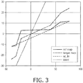
- Fig. 3 illustrates how a disparity mapping as provided for the reference 3D display device may be enhanced using the present invention.
- the thin black line in Fig. 3 represents the reference disparity mapping as received in combination with three-dimensional video data in a three-dimensional image signal. As can be seen from the graph the reference mapping is rather flat; i.e. the full range of the input disparity is mapped onto a fairly narrow output range.
- the figure also shows a thin dotted line corresponding with the identity curve.
- a particularly advantageous manner to do so is to derive an improvement factor based on the salience disparity ranges of the reference and target display devices and to use this improvement factor to perform a weighted addition of the reference disparity mapping and a linear approximation of the reference disparity mapping.
- mixing may be performed with a zero display disparity curve, in other words the target disparity mapping is adapted in vertical direction, by scaling using alpha.
- the target device could derive a smooth continuous curve from the resulting disparity mapping by applying cubic Hermite splines using three-point difference for internal points and one-sided difference at the end points and preserve monotonicity by applying the Fritch-Carlson method.
- Figure 4 shows a simplified flow-chart of a method of retargeting three-dimensional video signal data for use on a target three-dimensional display device.
- the method comprises a step 401 in which the three-dimensional video signal is received, the three-dimensional video signal comprising: three-dimensional video data suitable for driving a multi-view display device and reference disparity mapping data.
- the reference disparity mapping data is indicative of a disparity mapping for the three-dimensional video data for a reference three-dimensional display device.
- the method further comprises the step 402 of deriving a target disparity mapping based on the reference disparity mapping and characteristics of the reference three-dimensional display device and corresponding characteristics of the target three-dimensional display device.
- the characteristics of the target three-dimensional display device are available to the target display device and may be either stored in the device itself or may be accessible on request; e.g. they may be downloadable to the device.
- the characteristics of the reference device in turn may also be pre-distributed and embedded in the target device, or may be provided within the three-dimensional image signal itself.
- the method further comprises a step 403 of retargeting the three-dimensional video data using the target disparity mapping data into a target three-dimensional video data.
- the retargeting may comprise generating an image and accompanying on-screen disparity.
- image based rendering this may also involve image-based rendering in order to generate a multi-view image signal having the proper on-screen disparity.
- Figure 5 shows a simplified flow-chart of a method of generating a three-dimensional video signal, the three-dimensional video signal suitable for retargeting the three-dimensional video signal to a target three-dimensional display device.
- the method comprises a step 501 for obtaining three-dimensional video data suitable for driving a multi-view display device and a step 502 for obtaining characteristics of a reference three-dimensional display device. As there is no direct interdependency between these two steps, they may off course be executed in parallel or in reverse order.
- the method further comprises a step 503 for generating reference disparity mapping data, the reference disparity mapping data indicative of a disparity mapping for the three-dimensional video data for a reference three-dimensional display device and a step 504 for generating the three-dimensional video signal, wherein generating the three-dimensional video signal comprises combining the three-dimensional video data and the reference disparity mapping data.
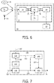
- Figure 6 shows a system 10 for retargeting a three-dimensional video signal 74 for use on a target three-dimensional display device 60.
- the system 10 comprises a receiver 30 arranged to receive the three-dimensional video signal 74.
- the three-dimensional video signal can be originate from a data carrier 71, such as an optical disc, a hard disk or non-volatile solid state storage device.
- the three dimensional video signal maybe received over a network connection 72, or over a wireless interface 73, which may possibly be a broadcast interface.
- the three-dimensional video signal 74 comprises three-dimensional video data suitable for driving a multi-view display device, and reference disparity mapping data.
- the reference disparity mapping data is indicative of a disparity mapping for the three-dimensional video data for a reference three-dimensional display device (not shown).
- the information is de-multiplexed and transmitted to a deriver 40.
- the deriver is arranged to derive a target disparity mapping based on the reference disparity mapping and characteristics of the reference three-dimensional display device and corresponding characteristics of the target three-dimensional display device.
- the deriver may retrieve part or all of the characteristic data 78 from non-volatile storage 70, or may alternatively obtain the characteristics of the reference device from the de-multiplexed three-dimensional image signal 75.
- the target disparity mapping data together with the three-dimensional video data is transmitted to a converter 50 arranged to retarget the three-dimensional video data using the target disparity mapping data into a target three-dimensional video data 77.
- the target three-dimensional video data 77 in turn maybe transmitted to a target display 60.
- the invention also envisages an integrated target three-dimensional display device 20 comprising the target display 60 and the integrated retargeting system 10.
- the three-dimensional video data is transmitted in conjunction with the reference disparity mapping data, it will be clear to those skilled in the art, that alternatively the three-dimensional video data can also bypass the deriver 60 and be transferred from the receiver 30 to the converter 50 directly.
- Figure 7 shows a system 110 for generating a three-dimensional video signal 74, the three-dimensional video signal being suitable for retargeting to a target three-dimensional display device.
- the system to this end comprises a receiver 120 arranged to receive three-dimensional video data 101 suitable for driving a multi-view display device.
- the system further comprises an acquisition unit 130 arranged to acquire characteristics 102 of a reference three-dimensional display device.
- the system 110 may comprise a non-volatile storage 160 comprising the characteristics 102 of the reference three-dimensional display device in case the generator is used for generating content for a particular type of display devices. Alternatively these characteristics 102' may originate from an external source.
- the system 110 further comprises a first generator 140 arranged to generate reference disparity mapping data 104, the reference disparity mapping data 104 is indicative of a disparity mapping for the three-dimensional video data 105 for a reference three-dimensional display device.
- the first generator 140 is arranged to receive the characteristics 103 as transmitted by the acquisition unit 130 as well as the three-dimensional video data 105 as received by the receiver 120.
- the system 110 further comprises a second generator 150 arranged to generate the three-dimensional video signal 74, wherein generating the three-dimensional video signal 74 comprises combining the three-dimensional video data 105 and the reference disparity mapping data 104 as received from the first generator.
- SEI messages When generating a video image signal, it is possible to encode additional information in so-called SEI messages.
- SEI messages may for example be added in to AVC (ISO/IEC 14496-10:2012 - Information technology - Coding of audio-visual objects - Part 2 10: Advanced Video Coding) or HEVC (ISO/IEC 23008-2:201x/FDIS - Information technology - High efficiency coding and media 13 delivery in heterogeneous environments - Part 2: High efficiency video coding) based video sequences.
- AVC ISO/IEC 14496-10:2012 - Information technology - Coding of audio-visual objects - Part 2 10: Advanced Video Coding
- HEVC ISO/IEC 23008-2:201x/FDIS - Information technology - High efficiency coding and media 13 delivery in heterogeneous environments - Part 2: High efficiency video coding
- Such metadata may be used to provide additional data to re-target the video image signal. Transmission of metadata elements across device interconnection links (such as in
- metadata is comprised in user data unregistered SEI messages. More preferably these SEI messages are included in the elementary stream that contains the depth or disparity information that is provided together with the three-dimensional video data.
- the depth can be transmitted in a single elementary stream with video and depth or disparity or alternatively as a separate disparity/depth elementary stream depending on the preferred manner of transport.
- SEI metadata message container syntax An example of the SEI metadata message container syntax is provided below. Table 1, SEI metadata message container syntax.
- uuid_xxxx can be used as an identifier to indicate the type of metadata, so as to allow an application parsing the incoming data to recognize the metadata and take appropriate action so as to retarget the three-dimensional video image signal based on the information provided.
- the metadata_type field can be used to provide additional information on the type of metadata comprised in the SEI message container.
- SEI metadata to provide additional information related to the reference disparity mapping, or for the characteristics of the reference three dimensional display device.
- SEI messages can be inserted in the stream at frame accurate positions and thus can be used to accurately adjust the disparity mapping when needed. This information may also be referred to as depth/disparity processing information.
- the depth processing information message may be used to provide depth format information and information on how depth should be remapped to displays with limited depth. Off course care should be taken so that information contained in these messages is kept consistent with possibly overlapping information in other SEI messages that may be included for consistency with other functions.
- the depth format information includes parameters that enable the display device to convert depth map data to disparity values in pixels.
- the content owner/creator has the possibility to optimize the mapping from depth map values to disparity values for the receiving display without the need to have detailed knowledge about the characteristics of all possible target displays.
- Part of the depth processing information may be updated with frame accuracy if desired, e.g. when salient objects are moving towards or away from the viewer.
- Remapping information may be included in the signal/bitstream by means of a curve that defines the relation between input disparity values and output values that relate to disparity on target displays with a limited depth range.
- mapping in-line with the present invention maybe utilized.
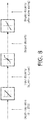
- Fig. 8 shows a graphical representation of the path from depth, to input/content disparity to output disparity and from output disparity to display disparity.
- the improvement is achieved by applying a transformation to the result of the reference disparity mapping.
- the horizontal resolution degradation as a function of disparity can be characterized by a single parameter alpha.
- Alpha values of the displays are required to be determined by the manufacturer according to a standardized method.
- the alpha value of the reference display that was used to determine the curve is included with the metadata.
- the target display device applies the curve and scales the output values in a linear fashion, depending on the ratio between the alpha of the reference display and the target display. As a result the sharpness degradation on the target device more or less resembles that on the reference device.
- any curve applied to the original disparities by the content author that is any mapping applied in the studio representing the artistic intent, is not affected.
- Table 2 An example of the syntax of the coding of a blur curve is provided in Table 2 below.
- Table 2 Depth processing information syntax depth_processing_information(metadataSize) ⁇ C
- the depth_coding_format indicates the manner in which depth is included in the bitstream.
- the depth_source_type in turn may specify the source of the content; which may e.g. indicate whether or not the content is CGI content, professional movie content, off line product broadcast content, or real-time broadcast content. In this manner the nature of the input content is clear and allows conclusions to be drawn based on the possible quality of the depth and/or e.g. whether scene changes are accurately detectable/encoded.
- the depth_representation value defines the meaning of how depth information is encoded; e.g. the depth_representation can indicate that the depth is uniformly quantized 0-255 inclusive in case of an 8-bit value. Alternatively it may be indicated that disparity values are being used instead of depth values.
- d_min defines the input disparity value in luminance pixels of the texture view that corresponds with decoded depth value 0.
- input disparity corresponds to the disparity as envisioned by the content author, so this disparity may also be referred to as content disparity.
- negative values of d_min correspond to virtual locations in front of the screen.
- d_max defines the input disparity value in luminance pixels of the texture view that corresponds with decoded depth value 255. So logically d_max is greater than d_min and together d_min and d_max define the disparity range to which depth value should be uniformly mapped/.
- the remapping type in turn may be used to indicate whether a fixed blur model remapping should be used or whether another remapping method should be used.
- the disparity remapping may be represented using a number of nodes as indicated in Table 2.
- num_curve_nodes is unequal to 0 this indicates that a (nonlinear) remapping should be applied to the input/content disparity values according to a remapping curve to optimize presentation of the 3D video content on an autostereoscopic display with a limited depth range.
- This field specifies the number of nodes that is included in the metadata to define the remapping curve. This field should be set to 0 if remapping_type is set to fixed blur.
- disparity_in[j] defines the input disparity value of the j-th node of the remapping curve.
- the nodes included in the metadata have increasing input disparity values. The first input disparity value has to be greater than or equal to the value of d_min. The last input disparity value has to be smaller than or equal to d_max.
- curve_out[j] in turn defines the output value of the j-th node of the curve.
- the curve out values should increase with increasing j.
- the target device should derive a smooth continuous curve from the nodes by applying cubic Hermite splines using three-point difference for internal points and one-sided difference at the end points and preserve monotonicity by applying the Fritch-Carlson method.
- the present invention has been described with reference to a three-dimensional image signal, wherein depth and/or disparity input was explicitly provided, it is noted that the present invention may also be used for retargeting stereoscopic of multi-view content in the absence of depth or disparity data, provided that a reference disparity mapping and characteristics of the reference and target 3D display devices are available.
- depth or disparity data can be estimated based on the stereo and/or multi-view content and one or more new views taking into account the remapped disparity maybe rendered using well known image based rendering techniques.
- the present invention may be used to map input depth and/or disparity data onto output or display disparity data in an advantageous manner.
- the present invention is particularly useful for autostereoscopic multi-view display devices as these typically have a more limited disparity range that can be utilized.
- the invention can be implemented in any suitable form including hardware, software, firmware or any combination of these.
- the invention may optionally be implemented at least partly as computer software running on one or more data processors and/or digital signal processors.
- the elements and components of an embodiment of the invention may be physically, functionally and logically implemented in any suitable way. Indeed the functionality may be implemented in a single unit, in a plurality of units or as part of other functional units. As such, the invention may be implemented in a single unit or may be physically and functionally distributed between different units, circuits and processors.
Landscapes
- Engineering & Computer Science (AREA)
- Multimedia (AREA)
- Signal Processing (AREA)
- Testing, Inspecting, Measuring Of Stereoscopic Televisions And Televisions (AREA)
- Control Of Indicators Other Than Cathode Ray Tubes (AREA)
Priority Applications (2)
| Application Number | Priority Date | Filing Date | Title |
|---|---|---|---|
| PL14778062T PL2982107T3 (pl) | 2013-04-05 | 2014-04-04 | Ponowne nakierowywanie sygnału trójwymiarowego obrazu |
| EP14778062.1A EP2982107B1 (en) | 2013-04-05 | 2014-04-04 | Re-targeting a three-dimensional image signal |
Applications Claiming Priority (3)
| Application Number | Priority Date | Filing Date | Title |
|---|---|---|---|
| EP13162505 | 2013-04-05 | ||
| PCT/US2014/032955 WO2014165744A1 (en) | 2013-04-05 | 2014-04-04 | Re-targeting a three-dimensional image signal |
| EP14778062.1A EP2982107B1 (en) | 2013-04-05 | 2014-04-04 | Re-targeting a three-dimensional image signal |
Publications (3)
| Publication Number | Publication Date |
|---|---|
| EP2982107A1 EP2982107A1 (en) | 2016-02-10 |
| EP2982107A4 EP2982107A4 (en) | 2016-04-13 |
| EP2982107B1 true EP2982107B1 (en) | 2017-11-22 |
Family
ID=48044688
Family Applications (1)
| Application Number | Title | Priority Date | Filing Date |
|---|---|---|---|
| EP14778062.1A Not-in-force EP2982107B1 (en) | 2013-04-05 | 2014-04-04 | Re-targeting a three-dimensional image signal |
Country Status (11)
| Country | Link |
|---|---|
| US (1) | US20160029012A1 (pt) |
| EP (1) | EP2982107B1 (pt) |
| JP (1) | JP2016521488A (pt) |
| CN (1) | CN105230011B (pt) |
| BR (1) | BR112015025077A2 (pt) |
| ES (1) | ES2658043T3 (pt) |
| MX (1) | MX355960B (pt) |
| PL (1) | PL2982107T3 (pt) |
| RU (1) | RU2015147002A (pt) |
| WO (1) | WO2014165744A1 (pt) |
| ZA (1) | ZA201508150B (pt) |
Families Citing this family (4)
| Publication number | Priority date | Publication date | Assignee | Title |
|---|---|---|---|---|
| CN105376553B (zh) * | 2015-11-24 | 2017-03-08 | 宁波大学 | 一种三维视频重定位方法 |
| CN106447702B (zh) * | 2016-08-31 | 2019-05-31 | 天津大学 | 一种立体图像匹配图计算方法 |
| EP3416381A1 (en) * | 2017-06-12 | 2018-12-19 | Thomson Licensing | Method and apparatus for providing information to a user observing a multi view content |
| US20200314411A1 (en) * | 2019-03-29 | 2020-10-01 | Alibaba Group Holding Limited | Synchronizing an illumination sequence of illumination sources with image capture in rolling shutter mode |
Family Cites Families (37)
| Publication number | Priority date | Publication date | Assignee | Title |
|---|---|---|---|---|
| US3480946A (en) * | 1966-03-31 | 1969-11-25 | Litton Precision Prod Inc | Successive approximation rotary angle to digital converter |
| US4397317A (en) * | 1980-04-17 | 1983-08-09 | Villa Real Antony Euclid C | Electronic blood pressure and pulse rate calculator with optional temperature indicator, timer and memory |
| JPH08106660A (ja) * | 1994-10-05 | 1996-04-23 | Canon Inc | 光磁気記録媒体及び該媒体を用いた情報再生方法 |
| US6635030B1 (en) * | 1999-04-09 | 2003-10-21 | B.H.B. Llc | Contrast injector for injecting a contrast medium to generate prolonged uniform vascular enhancement |
| US6055985A (en) * | 1999-04-09 | 2000-05-02 | B.H.B., L.C. | Methods for injecting a contrast medium to generate prolonged uniform vascular enhancement |
| US6873359B1 (en) * | 2000-09-29 | 2005-03-29 | Rockwell Science Center, Llc. | Self-adjusting, adaptive, minimal noise input amplifier circuit |
| US6504141B1 (en) * | 2000-09-29 | 2003-01-07 | Rockwell Science Center, Llc | Adaptive amplifier circuit with enhanced dynamic range |
| US6911995B2 (en) * | 2001-08-17 | 2005-06-28 | Mitsubishi Electric Research Labs, Inc. | Computer vision depth segmentation using virtual surface |
| US7097311B2 (en) * | 2003-04-19 | 2006-08-29 | University Of Kentucky Research Foundation | Super-resolution overlay in multi-projector displays |
| US20040223640A1 (en) * | 2003-05-09 | 2004-11-11 | Bovyrin Alexander V. | Stereo matching using segmentation of image columns |
| US8094927B2 (en) * | 2004-02-27 | 2012-01-10 | Eastman Kodak Company | Stereoscopic display system with flexible rendering of disparity map according to the stereoscopic fusing capability of the observer |
| JP4341564B2 (ja) * | 2005-02-25 | 2009-10-07 | 株式会社豊田中央研究所 | 対象物判定装置 |
| JP4605715B2 (ja) * | 2006-06-14 | 2011-01-05 | Kddi株式会社 | 多視点画像圧縮符号化方法、装置及びプログラム |
| WO2008079301A2 (en) * | 2006-12-21 | 2008-07-03 | Massachusetts Institute Of Technology | Methods and apparatus for 3d surface imaging using active wave-front sampling |
| US8593506B2 (en) * | 2007-03-15 | 2013-11-26 | Yissum Research Development Company Of The Hebrew University Of Jerusalem | Method and system for forming a panoramic image of a scene having minimal aspect distortion |
| JP5575659B2 (ja) * | 2007-12-14 | 2014-08-20 | コーニンクレッカ フィリップス エヌ ヴェ | ビデオ再生のための三次元モード選択メカニズム |
| EP2308241B1 (en) * | 2008-07-24 | 2017-04-12 | Koninklijke Philips N.V. | Versatile 3-d picture format |
| JP2010078883A (ja) * | 2008-09-25 | 2010-04-08 | Toshiba Corp | 立体映像表示装置及び立体映像表示方法 |
| KR101602904B1 (ko) * | 2008-10-10 | 2016-03-11 | 코닌클리케 필립스 엔.브이. | 신호에 포함된 시차 정보를 처리하는 방법 |
| EP2197217A1 (en) * | 2008-12-15 | 2010-06-16 | Koninklijke Philips Electronics N.V. | Image based 3D video format |
| DE102009012441B4 (de) * | 2009-03-12 | 2010-12-09 | Deutsches Zentrum für Luft- und Raumfahrt e.V. | Verfahren zur Reduktion des Speicherbedarfs bei der Bestimmung von Disparitätswerten für mindestens zwei stereoskopisch aufgenommene Bilder |
| RU2554465C2 (ru) * | 2009-07-27 | 2015-06-27 | Конинклейке Филипс Электроникс Н.В. | Комбинирование 3d видео и вспомогательных данных |
| RU2559735C2 (ru) * | 2009-09-16 | 2015-08-10 | Конинклейке Филипс Электроникс Н.В. | Компенсация размера трехмерного экрана |
| US8711204B2 (en) * | 2009-11-11 | 2014-04-29 | Disney Enterprises, Inc. | Stereoscopic editing for video production, post-production and display adaptation |
| US9445072B2 (en) * | 2009-11-11 | 2016-09-13 | Disney Enterprises, Inc. | Synthesizing views based on image domain warping |
| US9030530B2 (en) * | 2009-12-15 | 2015-05-12 | Thomson Licensing | Stereo-image quality and disparity/depth indications |
| US8730301B2 (en) * | 2010-03-12 | 2014-05-20 | Sony Corporation | Service linkage to caption disparity data transport |
| US8760498B2 (en) * | 2011-03-14 | 2014-06-24 | Sony Corporation | Disparity data transport in standard caption service |
| US9035939B2 (en) * | 2010-10-04 | 2015-05-19 | Qualcomm Incorporated | 3D video control system to adjust 3D video rendering based on user preferences |
| US8149268B1 (en) * | 2010-11-05 | 2012-04-03 | The United States Of America As Represented By The Secretary Of The Army | System and method for determining three-dimensional information from two-dimensional images |
| JP5242667B2 (ja) * | 2010-12-22 | 2013-07-24 | 株式会社東芝 | マップ変換方法、マップ変換装置及びマップ変換プログラム |
| US20120200670A1 (en) * | 2011-02-04 | 2012-08-09 | Nokia Corporation | Method and apparatus for a disparity limit indicator |
| JPWO2012176431A1 (ja) * | 2011-06-20 | 2015-02-23 | パナソニック株式会社 | 多視点画像生成装置、多視点画像生成方法 |
| US10805625B2 (en) * | 2011-07-05 | 2020-10-13 | Texas Instruments Incorporated | Method, system and computer program product for adjusting a stereoscopic image in response to decoded disparities between views of the stereoscopic image |
| CN102256152B (zh) * | 2011-07-15 | 2014-06-04 | 深圳超多维光电子有限公司 | 一种立体图像处理设备及方法 |
| US20130050187A1 (en) * | 2011-08-31 | 2013-02-28 | Zoltan KORCSOK | Method and Apparatus for Generating Multiple Image Views for a Multiview Autosteroscopic Display Device |
| US8982187B2 (en) * | 2011-09-19 | 2015-03-17 | Himax Technologies Limited | System and method of rendering stereoscopic images |
-
2014
- 2014-04-04 PL PL14778062T patent/PL2982107T3/pl unknown
- 2014-04-04 MX MX2015013890A patent/MX355960B/es active IP Right Grant
- 2014-04-04 WO PCT/US2014/032955 patent/WO2014165744A1/en active Application Filing
- 2014-04-04 RU RU2015147002A patent/RU2015147002A/ru not_active Application Discontinuation
- 2014-04-04 ES ES14778062.1T patent/ES2658043T3/es active Active
- 2014-04-04 CN CN201480019549.3A patent/CN105230011B/zh not_active Expired - Fee Related
- 2014-04-04 EP EP14778062.1A patent/EP2982107B1/en not_active Not-in-force
- 2014-04-04 BR BR112015025077A patent/BR112015025077A2/pt not_active IP Right Cessation
- 2014-04-04 JP JP2016506639A patent/JP2016521488A/ja not_active Ceased
- 2014-04-04 US US14/782,334 patent/US20160029012A1/en not_active Abandoned
-
2015
- 2015-11-04 ZA ZA2015/08150A patent/ZA201508150B/en unknown
Non-Patent Citations (1)
| Title |
|---|
| None * |
Also Published As
| Publication number | Publication date |
|---|---|
| MX355960B (es) | 2018-05-07 |
| CN105230011A (zh) | 2016-01-06 |
| JP2016521488A (ja) | 2016-07-21 |
| WO2014165744A1 (en) | 2014-10-09 |
| EP2982107A1 (en) | 2016-02-10 |
| CN105230011B (zh) | 2018-05-22 |
| ZA201508150B (en) | 2017-08-30 |
| ES2658043T3 (es) | 2018-03-08 |
| BR112015025077A2 (pt) | 2017-07-18 |
| RU2015147002A (ru) | 2017-05-12 |
| PL2982107T3 (pl) | 2018-06-29 |
| MX2015013890A (es) | 2016-08-11 |
| EP2982107A4 (en) | 2016-04-13 |
| US20160029012A1 (en) | 2016-01-28 |
| RU2015147002A3 (pt) | 2018-03-19 |
Similar Documents
| Publication | Publication Date | Title |
|---|---|---|
| US10080010B2 (en) | Method of encoding a video data signal for use with a multi-view rendering device | |
| US8447096B2 (en) | Method and device for processing a depth-map | |
| US8780173B2 (en) | Method and apparatus for reducing fatigue resulting from viewing three-dimensional image display, and method and apparatus for generating data stream of low visual fatigue three-dimensional image | |
| JP5734867B2 (ja) | 画像ベースの3dビデオフォーマット | |
| US8482654B2 (en) | Stereoscopic image format with depth information | |
| US9036006B2 (en) | Method and system for processing an input three dimensional video signal | |
| US9167226B2 (en) | Selecting viewpoints for generating additional views in 3D video | |
| US10158838B2 (en) | Methods and arrangements for supporting view synthesis | |
| US20110298898A1 (en) | Three dimensional image generating system and method accomodating multi-view imaging | |
| US9596446B2 (en) | Method of encoding a video data signal for use with a multi-view stereoscopic display device | |
| TWI558166B (zh) | 用於多視點裸視立體顯示器的深度地圖遞送格式 | |
| EP2982107B1 (en) | Re-targeting a three-dimensional image signal | |
| EP2688303A1 (en) | Recording device, recording method, playback device, playback method, program, and recording/playback device |
Legal Events
| Date | Code | Title | Description |
|---|---|---|---|
| PUAI | Public reference made under article 153(3) epc to a published international application that has entered the european phase |
Free format text: ORIGINAL CODE: 0009012 |
|
| 17P | Request for examination filed |
Effective date: 20151105 |
|
| AK | Designated contracting states |
Kind code of ref document: A1 Designated state(s): AL AT BE BG CH CY CZ DE DK EE ES FI FR GB GR HR HU IE IS IT LI LT LU LV MC MK MT NL NO PL PT RO RS SE SI SK SM TR |
|
| AX | Request for extension of the european patent |
Extension state: BA ME |
|
| A4 | Supplementary search report drawn up and despatched |
Effective date: 20160315 |
|
| RIC1 | Information provided on ipc code assigned before grant |
Ipc: H04N 13/00 20060101AFI20160309BHEP Ipc: H04N 13/04 20060101ALI20160309BHEP |
|
| DAX | Request for extension of the european patent (deleted) | ||
| GRAP | Despatch of communication of intention to grant a patent |
Free format text: ORIGINAL CODE: EPIDOSNIGR1 |
|
| INTG | Intention to grant announced |
Effective date: 20170616 |
|
| GRAS | Grant fee paid |
Free format text: ORIGINAL CODE: EPIDOSNIGR3 |
|
| GRAA | (expected) grant |
Free format text: ORIGINAL CODE: 0009210 |
|
| AK | Designated contracting states |
Kind code of ref document: B1 Designated state(s): AL AT BE BG CH CY CZ DE DK EE ES FI FR GB GR HR HU IE IS IT LI LT LU LV MC MK MT NL NO PL PT RO RS SE SI SK SM TR |
|
| REG | Reference to a national code |
Ref country code: GB Ref legal event code: FG4D |
|
| REG | Reference to a national code |
Ref country code: CH Ref legal event code: EP |
|
| REG | Reference to a national code |
Ref country code: IE Ref legal event code: FG4D |
|
| REG | Reference to a national code |
Ref country code: AT Ref legal event code: REF Ref document number: 949405 Country of ref document: AT Kind code of ref document: T Effective date: 20171215 |
|
| REG | Reference to a national code |
Ref country code: DE Ref legal event code: R096 Ref document number: 602014017655 Country of ref document: DE |
|
| REG | Reference to a national code |
Ref country code: ES Ref legal event code: FG2A Ref document number: 2658043 Country of ref document: ES Kind code of ref document: T3 Effective date: 20180308 |
|
| REG | Reference to a national code |
Ref country code: NL Ref legal event code: MP Effective date: 20171122 |
|
| REG | Reference to a national code |
Ref country code: LT Ref legal event code: MG4D |
|
| REG | Reference to a national code |
Ref country code: AT Ref legal event code: MK05 Ref document number: 949405 Country of ref document: AT Kind code of ref document: T Effective date: 20171122 |
|
| REG | Reference to a national code |
Ref country code: FR Ref legal event code: PLFP Year of fee payment: 5 |
|
| PG25 | Lapsed in a contracting state [announced via postgrant information from national office to epo] |
Ref country code: LT Free format text: LAPSE BECAUSE OF FAILURE TO SUBMIT A TRANSLATION OF THE DESCRIPTION OR TO PAY THE FEE WITHIN THE PRESCRIBED TIME-LIMIT Effective date: 20171122 Ref country code: SE Free format text: LAPSE BECAUSE OF FAILURE TO SUBMIT A TRANSLATION OF THE DESCRIPTION OR TO PAY THE FEE WITHIN THE PRESCRIBED TIME-LIMIT Effective date: 20171122 Ref country code: FI Free format text: LAPSE BECAUSE OF FAILURE TO SUBMIT A TRANSLATION OF THE DESCRIPTION OR TO PAY THE FEE WITHIN THE PRESCRIBED TIME-LIMIT Effective date: 20171122 Ref country code: NO Free format text: LAPSE BECAUSE OF FAILURE TO SUBMIT A TRANSLATION OF THE DESCRIPTION OR TO PAY THE FEE WITHIN THE PRESCRIBED TIME-LIMIT Effective date: 20180222 Ref country code: NL Free format text: LAPSE BECAUSE OF FAILURE TO SUBMIT A TRANSLATION OF THE DESCRIPTION OR TO PAY THE FEE WITHIN THE PRESCRIBED TIME-LIMIT Effective date: 20171122 |
|
| PG25 | Lapsed in a contracting state [announced via postgrant information from national office to epo] |
Ref country code: GR Free format text: LAPSE BECAUSE OF FAILURE TO SUBMIT A TRANSLATION OF THE DESCRIPTION OR TO PAY THE FEE WITHIN THE PRESCRIBED TIME-LIMIT Effective date: 20180223 Ref country code: BG Free format text: LAPSE BECAUSE OF FAILURE TO SUBMIT A TRANSLATION OF THE DESCRIPTION OR TO PAY THE FEE WITHIN THE PRESCRIBED TIME-LIMIT Effective date: 20180222 Ref country code: AT Free format text: LAPSE BECAUSE OF FAILURE TO SUBMIT A TRANSLATION OF THE DESCRIPTION OR TO PAY THE FEE WITHIN THE PRESCRIBED TIME-LIMIT Effective date: 20171122 Ref country code: LV Free format text: LAPSE BECAUSE OF FAILURE TO SUBMIT A TRANSLATION OF THE DESCRIPTION OR TO PAY THE FEE WITHIN THE PRESCRIBED TIME-LIMIT Effective date: 20171122 Ref country code: RS Free format text: LAPSE BECAUSE OF FAILURE TO SUBMIT A TRANSLATION OF THE DESCRIPTION OR TO PAY THE FEE WITHIN THE PRESCRIBED TIME-LIMIT Effective date: 20171122 Ref country code: HR Free format text: LAPSE BECAUSE OF FAILURE TO SUBMIT A TRANSLATION OF THE DESCRIPTION OR TO PAY THE FEE WITHIN THE PRESCRIBED TIME-LIMIT Effective date: 20171122 |
|
| PG25 | Lapsed in a contracting state [announced via postgrant information from national office to epo] |
Ref country code: SK Free format text: LAPSE BECAUSE OF FAILURE TO SUBMIT A TRANSLATION OF THE DESCRIPTION OR TO PAY THE FEE WITHIN THE PRESCRIBED TIME-LIMIT Effective date: 20171122 Ref country code: CZ Free format text: LAPSE BECAUSE OF FAILURE TO SUBMIT A TRANSLATION OF THE DESCRIPTION OR TO PAY THE FEE WITHIN THE PRESCRIBED TIME-LIMIT Effective date: 20171122 Ref country code: DK Free format text: LAPSE BECAUSE OF FAILURE TO SUBMIT A TRANSLATION OF THE DESCRIPTION OR TO PAY THE FEE WITHIN THE PRESCRIBED TIME-LIMIT Effective date: 20171122 Ref country code: CY Free format text: LAPSE BECAUSE OF FAILURE TO SUBMIT A TRANSLATION OF THE DESCRIPTION OR TO PAY THE FEE WITHIN THE PRESCRIBED TIME-LIMIT Effective date: 20171122 Ref country code: EE Free format text: LAPSE BECAUSE OF FAILURE TO SUBMIT A TRANSLATION OF THE DESCRIPTION OR TO PAY THE FEE WITHIN THE PRESCRIBED TIME-LIMIT Effective date: 20171122 |
|
| PGFP | Annual fee paid to national office [announced via postgrant information from national office to epo] |
Ref country code: ES Payment date: 20180522 Year of fee payment: 5 |
|
| REG | Reference to a national code |
Ref country code: DE Ref legal event code: R097 Ref document number: 602014017655 Country of ref document: DE |
|
| PG25 | Lapsed in a contracting state [announced via postgrant information from national office to epo] |
Ref country code: SM Free format text: LAPSE BECAUSE OF FAILURE TO SUBMIT A TRANSLATION OF THE DESCRIPTION OR TO PAY THE FEE WITHIN THE PRESCRIBED TIME-LIMIT Effective date: 20171122 Ref country code: RO Free format text: LAPSE BECAUSE OF FAILURE TO SUBMIT A TRANSLATION OF THE DESCRIPTION OR TO PAY THE FEE WITHIN THE PRESCRIBED TIME-LIMIT Effective date: 20171122 |
|
| PGFP | Annual fee paid to national office [announced via postgrant information from national office to epo] |
Ref country code: IT Payment date: 20180420 Year of fee payment: 5 Ref country code: TR Payment date: 20180402 Year of fee payment: 5 Ref country code: PL Payment date: 20180403 Year of fee payment: 5 Ref country code: FR Payment date: 20180426 Year of fee payment: 5 |
|
| PLBE | No opposition filed within time limit |
Free format text: ORIGINAL CODE: 0009261 |
|
| STAA | Information on the status of an ep patent application or granted ep patent |
Free format text: STATUS: NO OPPOSITION FILED WITHIN TIME LIMIT |
|
| 26N | No opposition filed |
Effective date: 20180823 |
|
| PGFP | Annual fee paid to national office [announced via postgrant information from national office to epo] |
Ref country code: DE Payment date: 20180629 Year of fee payment: 5 Ref country code: GB Payment date: 20180427 Year of fee payment: 5 |
|
| PG25 | Lapsed in a contracting state [announced via postgrant information from national office to epo] |
Ref country code: SI Free format text: LAPSE BECAUSE OF FAILURE TO SUBMIT A TRANSLATION OF THE DESCRIPTION OR TO PAY THE FEE WITHIN THE PRESCRIBED TIME-LIMIT Effective date: 20171122 Ref country code: MC Free format text: LAPSE BECAUSE OF FAILURE TO SUBMIT A TRANSLATION OF THE DESCRIPTION OR TO PAY THE FEE WITHIN THE PRESCRIBED TIME-LIMIT Effective date: 20171122 |
|
| REG | Reference to a national code |
Ref country code: CH Ref legal event code: PL |
|
| REG | Reference to a national code |
Ref country code: BE Ref legal event code: MM Effective date: 20180430 |
|
| REG | Reference to a national code |
Ref country code: IE Ref legal event code: MM4A |
|
| PG25 | Lapsed in a contracting state [announced via postgrant information from national office to epo] |
Ref country code: LU Free format text: LAPSE BECAUSE OF NON-PAYMENT OF DUE FEES Effective date: 20180404 |
|
| PG25 | Lapsed in a contracting state [announced via postgrant information from national office to epo] |
Ref country code: LI Free format text: LAPSE BECAUSE OF NON-PAYMENT OF DUE FEES Effective date: 20180430 Ref country code: CH Free format text: LAPSE BECAUSE OF NON-PAYMENT OF DUE FEES Effective date: 20180430 Ref country code: BE Free format text: LAPSE BECAUSE OF NON-PAYMENT OF DUE FEES Effective date: 20180430 |
|
| PG25 | Lapsed in a contracting state [announced via postgrant information from national office to epo] |
Ref country code: IE Free format text: LAPSE BECAUSE OF NON-PAYMENT OF DUE FEES Effective date: 20180404 |
|
| REG | Reference to a national code |
Ref country code: DE Ref legal event code: R119 Ref document number: 602014017655 Country of ref document: DE |
|
| GBPC | Gb: european patent ceased through non-payment of renewal fee |
Effective date: 20190404 |
|
| PG25 | Lapsed in a contracting state [announced via postgrant information from national office to epo] |
Ref country code: GB Free format text: LAPSE BECAUSE OF NON-PAYMENT OF DUE FEES Effective date: 20190404 Ref country code: DE Free format text: LAPSE BECAUSE OF NON-PAYMENT OF DUE FEES Effective date: 20191101 Ref country code: MT Free format text: LAPSE BECAUSE OF NON-PAYMENT OF DUE FEES Effective date: 20180404 |
|
| PG25 | Lapsed in a contracting state [announced via postgrant information from national office to epo] |
Ref country code: FR Free format text: LAPSE BECAUSE OF NON-PAYMENT OF DUE FEES Effective date: 20190430 |
|
| PG25 | Lapsed in a contracting state [announced via postgrant information from national office to epo] |
Ref country code: IT Free format text: LAPSE BECAUSE OF NON-PAYMENT OF DUE FEES Effective date: 20190404 |
|
| PG25 | Lapsed in a contracting state [announced via postgrant information from national office to epo] |
Ref country code: PT Free format text: LAPSE BECAUSE OF FAILURE TO SUBMIT A TRANSLATION OF THE DESCRIPTION OR TO PAY THE FEE WITHIN THE PRESCRIBED TIME-LIMIT Effective date: 20171122 |
|
| PG25 | Lapsed in a contracting state [announced via postgrant information from national office to epo] |
Ref country code: HU Free format text: LAPSE BECAUSE OF FAILURE TO SUBMIT A TRANSLATION OF THE DESCRIPTION OR TO PAY THE FEE WITHIN THE PRESCRIBED TIME-LIMIT; INVALID AB INITIO Effective date: 20140404 Ref country code: MK Free format text: LAPSE BECAUSE OF NON-PAYMENT OF DUE FEES Effective date: 20171122 |
|
| PG25 | Lapsed in a contracting state [announced via postgrant information from national office to epo] |
Ref country code: AL Free format text: LAPSE BECAUSE OF FAILURE TO SUBMIT A TRANSLATION OF THE DESCRIPTION OR TO PAY THE FEE WITHIN THE PRESCRIBED TIME-LIMIT Effective date: 20171122 Ref country code: IS Free format text: LAPSE BECAUSE OF FAILURE TO SUBMIT A TRANSLATION OF THE DESCRIPTION OR TO PAY THE FEE WITHIN THE PRESCRIBED TIME-LIMIT Effective date: 20180322 |
|
| REG | Reference to a national code |
Ref country code: ES Ref legal event code: FD2A Effective date: 20200828 |
|
| PG25 | Lapsed in a contracting state [announced via postgrant information from national office to epo] |
Ref country code: ES Free format text: LAPSE BECAUSE OF NON-PAYMENT OF DUE FEES Effective date: 20190405 |
|
| PG25 | Lapsed in a contracting state [announced via postgrant information from national office to epo] |
Ref country code: PL Free format text: LAPSE BECAUSE OF NON-PAYMENT OF DUE FEES Effective date: 20190404 |
|
| PG25 | Lapsed in a contracting state [announced via postgrant information from national office to epo] |
Ref country code: TR Free format text: LAPSE BECAUSE OF NON-PAYMENT OF DUE FEES Effective date: 20190404 |