EP2981703B1 - Fuel injection valve - Google Patents
Fuel injection valve Download PDFInfo
- Publication number
- EP2981703B1 EP2981703B1 EP14718734.8A EP14718734A EP2981703B1 EP 2981703 B1 EP2981703 B1 EP 2981703B1 EP 14718734 A EP14718734 A EP 14718734A EP 2981703 B1 EP2981703 B1 EP 2981703B1
- Authority
- EP
- European Patent Office
- Prior art keywords
- nozzle hole
- end portion
- open end
- side open
- fuel
- Prior art date
- Legal status (The legal status is an assumption and is not a legal conclusion. Google has not performed a legal analysis and makes no representation as to the accuracy of the status listed.)
- Not-in-force
Links
- 239000000446 fuel Substances 0.000 title claims description 297
- 238000002347 injection Methods 0.000 title claims description 117
- 239000007924 injection Substances 0.000 title claims description 117
- 239000007788 liquid Substances 0.000 description 39
- 238000000889 atomisation Methods 0.000 description 19
- 230000002093 peripheral effect Effects 0.000 description 18
- 230000002452 interceptive effect Effects 0.000 description 2
- 238000003754 machining Methods 0.000 description 2
- 230000001737 promoting effect Effects 0.000 description 2
- 238000002485 combustion reaction Methods 0.000 description 1
- 239000000470 constituent Substances 0.000 description 1
- 238000012986 modification Methods 0.000 description 1
- 230000004048 modification Effects 0.000 description 1
- 239000002245 particle Substances 0.000 description 1
- 238000003466 welding Methods 0.000 description 1
Images




Classifications
-
- F—MECHANICAL ENGINEERING; LIGHTING; HEATING; WEAPONS; BLASTING
- F02—COMBUSTION ENGINES; HOT-GAS OR COMBUSTION-PRODUCT ENGINE PLANTS
- F02M—SUPPLYING COMBUSTION ENGINES IN GENERAL WITH COMBUSTIBLE MIXTURES OR CONSTITUENTS THEREOF
- F02M61/00—Fuel-injectors not provided for in groups F02M39/00 - F02M57/00 or F02M67/00
- F02M61/16—Details not provided for in, or of interest apart from, the apparatus of groups F02M61/02 - F02M61/14
- F02M61/18—Injection nozzles, e.g. having valve seats; Details of valve member seated ends, not otherwise provided for
- F02M61/1806—Injection nozzles, e.g. having valve seats; Details of valve member seated ends, not otherwise provided for characterised by the arrangement of discharge orifices, e.g. orientation or size
- F02M61/1833—Discharge orifices having changing cross sections, e.g. being divergent
-
- F—MECHANICAL ENGINEERING; LIGHTING; HEATING; WEAPONS; BLASTING
- F02—COMBUSTION ENGINES; HOT-GAS OR COMBUSTION-PRODUCT ENGINE PLANTS
- F02M—SUPPLYING COMBUSTION ENGINES IN GENERAL WITH COMBUSTIBLE MIXTURES OR CONSTITUENTS THEREOF
- F02M61/00—Fuel-injectors not provided for in groups F02M39/00 - F02M57/00 or F02M67/00
- F02M61/16—Details not provided for in, or of interest apart from, the apparatus of groups F02M61/02 - F02M61/14
- F02M61/18—Injection nozzles, e.g. having valve seats; Details of valve member seated ends, not otherwise provided for
- F02M61/1806—Injection nozzles, e.g. having valve seats; Details of valve member seated ends, not otherwise provided for characterised by the arrangement of discharge orifices, e.g. orientation or size
- F02M61/184—Discharge orifices having non circular sections
-
- F—MECHANICAL ENGINEERING; LIGHTING; HEATING; WEAPONS; BLASTING
- F02—COMBUSTION ENGINES; HOT-GAS OR COMBUSTION-PRODUCT ENGINE PLANTS
- F02M—SUPPLYING COMBUSTION ENGINES IN GENERAL WITH COMBUSTIBLE MIXTURES OR CONSTITUENTS THEREOF
- F02M61/00—Fuel-injectors not provided for in groups F02M39/00 - F02M57/00 or F02M67/00
- F02M61/16—Details not provided for in, or of interest apart from, the apparatus of groups F02M61/02 - F02M61/14
- F02M61/18—Injection nozzles, e.g. having valve seats; Details of valve member seated ends, not otherwise provided for
- F02M61/1806—Injection nozzles, e.g. having valve seats; Details of valve member seated ends, not otherwise provided for characterised by the arrangement of discharge orifices, e.g. orientation or size
- F02M61/1846—Dimensional characteristics of discharge orifices
-
- F—MECHANICAL ENGINEERING; LIGHTING; HEATING; WEAPONS; BLASTING
- F02—COMBUSTION ENGINES; HOT-GAS OR COMBUSTION-PRODUCT ENGINE PLANTS
- F02M—SUPPLYING COMBUSTION ENGINES IN GENERAL WITH COMBUSTIBLE MIXTURES OR CONSTITUENTS THEREOF
- F02M61/00—Fuel-injectors not provided for in groups F02M39/00 - F02M57/00 or F02M67/00
- F02M61/16—Details not provided for in, or of interest apart from, the apparatus of groups F02M61/02 - F02M61/14
- F02M61/18—Injection nozzles, e.g. having valve seats; Details of valve member seated ends, not otherwise provided for
- F02M61/1853—Orifice plates
-
- F—MECHANICAL ENGINEERING; LIGHTING; HEATING; WEAPONS; BLASTING
- F02—COMBUSTION ENGINES; HOT-GAS OR COMBUSTION-PRODUCT ENGINE PLANTS
- F02M—SUPPLYING COMBUSTION ENGINES IN GENERAL WITH COMBUSTIBLE MIXTURES OR CONSTITUENTS THEREOF
- F02M63/00—Other fuel-injection apparatus having pertinent characteristics not provided for in groups F02M39/00 - F02M57/00 or F02M67/00; Details, component parts, or accessories of fuel-injection apparatus, not provided for in, or of interest apart from, the apparatus of groups F02M39/00 - F02M61/00 or F02M67/00; Combination of fuel pump with other devices, e.g. lubricating oil pump
- F02M63/0012—Valves
- F02M63/007—Details not provided for in, or of interest apart from, the apparatus of the groups F02M63/0014 - F02M63/0059
- F02M63/0078—Valve member details, e.g. special shape, hollow or fuel passages in the valve member
- F02M63/008—Hollow valve members, e.g. members internally guided
Definitions
- the nozzle hole may be formed such that the entry-side open end portion is adjacent to an edge portion of the valve hole.
- the fuel injection valve 1 performs a fuel injection with fuel being delivered from the pump, not shown, into the fuel supply passage 11 of the valve body 10.
- fuel in the fuel supply passage 11 is made to flow into the nozzle hole 31 via a gap between the valve seat 13 and the outer peripheral surface portion of the lower end portion of the valve element 20, and the valve hole 12, and is injected out in a downward direction from the exit-side open end portion 31b of the nozzle hole 31.
- the fuel injection valve 1 makes the thickness h of the fuel liquid film in the direction of the long axis X2 of the exit-side open end portion 31b thin, and sufficiently spreads the liquid fuel film in the direction of the short axis Y2 of the exit-side open end portion 31b, so atomization of the fuel droplets is able to be effectively promoted.
- the fuel liquid film thickness is able to be made thin by making the flow path cross-section of the entry-side open end portion 31a satisfy the relationship of 1 ⁇ Ld / Sd ⁇ 3.5.
- the nozzle hole 32 is formed such that a second angle ⁇ 2 that is an intersecting angle of opposing nozzle hole inner wall surface portions 32e and 32f in an oblique section (see FIG. 4D ) along the short axes Y1 and Y2 of the entry-side open end portion 32a and the exit-side open end portion 32b, is greater than a first angle ⁇ 1 that is an intersecting angle of opposing nozzle hole inner wall surface portions 32c and 32d in a longitudinal section (see FIG. 4A ) along the long axes X1 and X2 of the entry-side open end portion 32a and the exit-side open end portion 32b.
- reference character Z represents an axis of the nozzle hole 32.
- the fuel injection valve 2 performs a fuel injection with fuel being delivered from the pump, not shown, into the fuel supply passage 11 of the valve body 10.
- fuel in the fuel supply passage 11 is made to flow into the nozzle hole 31 via a gap between the valve seat 13 and the outer peripheral surface portion of the lower end portion of the valve element 20, and the valve hole 12, and is injected out in a downward direction from the exit-side open end portion 32b of the nozzle hole 32.
- the nozzle hole 32 of the nozzle hole plate 30 is formed such that the second angle ⁇ 2 that is the intersecting angle of the opposing nozzle hole inner wall surface portions 32e and 32f in the oblique section along the short axes Y1 and Y2 of the entry-side open end portion 32a and the exit-side open end portion 32b, is greater than the first angle ⁇ 1 that is the intersecting angle of the opposing nozzle hole inner wall surface portions 32c and 32d in the longitudinal section along the long axes X1 and X2 of the entry-side open end portion 32a and the exit-side open end portion 32b.
- the nozzle hole 32 is such that the outside angle ⁇ 2f that is the intersecting angle between the axis Z and the nozzle hole inner wall surface portion 32f is larger than the inside angle ⁇ 2e that is the intersecting angle between the axis Z and the nozzle hole inner wall surface portion 32e, in the oblique section along the short axes Y1 and Y2 of the entry-side open end portion 32a and the exit-side open end portion 32b (see FIG. 4D ).
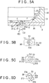
- the nozzle hole 33 is formed with a flow path cross-section having an oval shape that has long axes X1 and X2 and short axes Y1 and Y2, in a plan view with respect to the nozzle hole plate 30 shown in FIG. 5B .
- the long axis X1 and the short axis Y1 belong to an entry-side open end portion 33a that is positioned on the valve body 10 side (the upper side in FIG. 5A ) of the nozzle hole 33
- the long axis X2 and the short axis Y2 belong to an exit-side open end portion 33b that is positioned on the opposite side from the valve body 10 (i.e., on the lower side in FIG. 5A ) of the nozzle hole 33.
- the flow path cross-section of the exit-side open end portion 33b of the nozzle hole 33 is formed asymmetrical with respect to the short axis Y2.
- the fuel injection valve 3 performs a fuel injection with fuel being delivered from the pump, not shown, into the fuel supply passage 11 of the valve body 10.
- fuel in the fuel supply passage 11 is made to flow into the nozzle hole 33 via a gap between the valve seat 13 and the outer peripheral surface portion of the lower end portion of the valve element 20, and the valve hole 12, and is injected out in a downward direction from the exit-side open end portion 33b of the nozzle hole 33.
- the fuel injection valve 3 is able to inject fuel downward so that it spreads out in the direction of the short axis Y2 of the exit-side open end portion 33b from the nozzle hole 33. Also, the fuel injection valve 3 generates the flow F of fuel that is close to the inner wall surface portion 33c of the nozzle hole 33, and thus creates negative pressure in a region on the inner wall surface portion 33d side inside the nozzle hole 33. As a result, a flow A of outside air is able to be sucked into the nozzle hole 33.
- the fuel injection valve 3 makes the thickness h of the fuel liquid film in the direction of the long axis X2 of the exit-side open end portion 33b thin (see FIG. 2 ), and sufficiently spreads the liquid fuel film in the direction of the short axis Y2 of the exit-side open end portion 33b, so atomization of the fuel droplets is able to be effectively promoted.
- the fuel injection valve 3 sufficiently spreads the fuel liquid film in the direction of the long axis X2 of the exit-side open end portion 33b, and increases the amount of air sucked into the nozzle hole 33 from outside, so atomization of the fuel droplets is able to be effectively promoted.
- a fuel injection valve 4 according to a fourth example embodiment of the invention includes a valve body 10, a valve element 20, and a nozzle hole plate 30, as shown in FIG. 6A .
- a plurality of nozzle holes 34 that extend through in a plate thickness direction are provided in the nozzle hole plate 30.
- these nozzle holes 34 will be described in the singular to simplify the description.
- the nozzle hole 34 is formed with a flow path cross-section having an oval shape that has long axes X1 and X2 and short axes Y1 and Y2, in a plan view with respect to the nozzle hole plate 30 shown in FIG. 6B .
- the long axis X1 and the short axis Y1 belong to an entry-side open end portion 34a that is positioned on the valve body 10 side (the upper side in FIG. 6A ) of the nozzle hole 34
- the long axis X2 and the short axis Y2 belong to an exit-side open end portion 34b that is positioned on the opposite side from the valve body 10 (i.e., on the lower side in FIG. 6A ) of the nozzle hole 34.
- the nozzle hole 34 is formed such that a second angle ⁇ 2 that is an intersecting angle of opposing nozzle hole inner wall surface portions 34e and 34f in an oblique section (see FIGS. 6C and 6D ) along the short axis Y2 of the exit-side open end portion 34b, is greater than a first angle ⁇ 1 that is an intersecting angle of opposing nozzle hole inner wall surface portions 34c and 34d in a longitudinal section (see FIG. 6A ) along the long axis X2 of the exit-side open end portion 34b.
- reference character Z represents an axis of the nozzle hole 34.
- the nozzle hole 34 is formed such that the long axis X1 of the entry-side open end portion 34a extends toward the center O of the valve hole 12, in a plan view with respect to the nozzle hole plate 30 (see FIG. 6E ).
- the fuel injection valve 4 performs a fuel injection with fuel being delivered from the pump, not shown, into the fuel supply passage 11 of the valve body 10.
- fuel in the fuel supply passage 11 is made to flow into the nozzle hole 34 via a gap between the valve seat 13 and the outer peripheral surface portion of the lower end portion of the valve element 20, and the valve hole 12, and is injected out in a downward direction from the exit-side open end portion 34b of the nozzle hole 34.
- the fuel injection valve 4 is able to inject fuel downward so that it spreads out in the direction of the short axis Y2 of the exit-side open end portion 34b from the nozzle hole 34. Also, the fuel injection valve 4 generates the flow F of fuel that is close to the inner wall surface portion 34c of the nozzle hole 34, and thus creates negative pressure in a region on the inner wall surface portion 34d side inside the nozzle hole 34. As a result, a flow A of outside air is able to be sucked into the nozzle hole 34.
- the nozzle hole 34 of the nozzle hole plate 30 is formed such that the long axis X1 of the entry-side open end portion 34a extends toward the center O of the valve hole 12, so a flow F of fuel that is close to the inner wall surface portion 34c side of the nozzle hole 34 is generated, which causes boundary layer peeling to occur in the fuel that flows through the nozzle hole 34.
- the nozzle hole 35 is formed with a flow path cross-section having an oval shape that has long axes X1 and X2 and short axes Y1 and Y2, in a plan view with respect to the nozzle hole plate 30 shown in FIG. 7B .
- the long axis X1 and the short axis Y1 belong to an entry-side open end portion 35a that is positioned on the valve body 10 side (the upper side in FIG. 7A ) of the nozzle hole 35
- the long axis X2 and the short axis Y2 belong to an exit-side open end portion 35b that is positioned on the opposite side from the valve body 10 (i.e., on the lower side in FIG. 7A ) of the nozzle hole 35.
- the nozzle hole 35 is formed in a tapered shape such that a flow path sectional area becomes larger from the entry-side open end portion 35a toward the exit-side open end portion 35b.
- the nozzle hole 35 is formed such that the center of the exit-side open end portion 35b (i.e., the point of intersection between the long axis X2 and the short axis Y2) is positioned farther toward an outer edge portion side of the nozzle hole plate 30 than the center of the entry-side open end portion 35a (i.e., the point of intersection between the long axis X1 and the short axis Y1) is.
- the nozzle hole 35 is formed such that a second angle ⁇ 2 that is an intersecting angle of opposing nozzle hole inner wall surface portions 35e and 35f in an oblique section (see FIGS. 7C and 7D ) along the short axes Y1 and Y2 of the entry-side open end portion 35a and the exit-side open end portion 35b, is greater than a first angle ⁇ 1 that is an intersecting angle of opposing nozzle hole inner wall surface portions 35c and 35d in a longitudinal section (see FIG. 7A ) along the long axes X1 and X2 of the entry-side open end portion 35a and the exit-side open end portion 35b.
- reference character Z represents an axis of the nozzle hole 35.
- the fuel injection valve 5 performs a fuel injection with fuel being delivered from the pump, not shown, into the fuel supply passage 11 of the valve body 10. That is, in the fuel injection valve 5, when the valve element 20 is lifted upward by the valve driving device, not shown, fuel in the fuel supply passage 11 is made to flow into the nozzle hole 35 via a gap between the valve seat 13 and the outer peripheral surface portion of the lower end portion of the valve element 20, and the valve hole 12, and is injected out in a downward direction from the exit-side open end portion 35b of the nozzle hole 35.
- the fuel injected from the fuel injection valve 5 expands the fuel liquid film cross-section as the fuel becomes farther away from the exit-side open end portion 35b, but the fuel droplets diffuse from the fuel main flow, so the fuel liquid film cross-section gradually shrinks and finally disappears.
- the nozzle hole 35 of the nozzle hole plate 30 is formed such that the second angle ⁇ 2 that is the intersecting angle of the opposing nozzle hole inner wall surface portions 35e and 35f in the oblique section along the short axes Y1 and Y2 of the entry-side open end portion 35a and the exit-side open end portion 35b, is greater than the first angle ⁇ 1 that is the intersecting angle of the opposing nozzle hole inner wall surface portions 35c and 35d in the longitudinal section along the long axes X1 and X2 of the entry-side open end portion 35a and the exit-side open end portion 35b.
- the fuel injection valve 5 is able to inject fuel downward so that it spreads out in the direction of the short axis Y2 of the exit-side open end portion 35b from the nozzle hole 35. Also, the fuel injection valve 5 generates the flow F of fuel that is close to the inner wall surface portion 35c of the nozzle hole 35, and thus creates negative pressure in a region on the inner wall surface portion 35d side inside the nozzle hole 35. As a result, a flow A of outside air is able to be sucked into the nozzle hole 35.
- the fuel injection valve 5 makes the thickness h of the fuel liquid film in the direction of the long axis X2 of the exit-side open end portion 35b thin (see FIG. 2 ), and sufficiently spreads the liquid fuel film in the direction of the short axis Y2 of the exit-side open end portion 35b, so atomization of the fuel droplets is able to be effectively promoted.
- the nozzle hole 35 of the nozzle hole plate 30 is formed such that the entry-side open end portion 35a is adjacent to the inner peripheral edge portion of the valve hole 12 of the valve body 10. Therefore, the fuel injection valve 5 leads the fuel that flows between the valve seat 13 of the valve body 10 and the outer peripheral surface portion of the valve element 20 directly to the nozzle hole 35.
- the fuel injection valve 5 keeps the disturbance in the flow of fuel that flows through the valve body 10 from attenuating easily, so atomization of the fuel droplets is able to be effectively promoted.
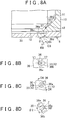
- a fuel injection valve 6 includes a valve body 10, a valve element 20, and a nozzle hole plate 30, as shown in FIG. 8A .
- a plurality of nozzle holes 36 that extend through in a plate thickness direction are provided in the nozzle hole plate 30.
- these nozzle holes 36 will be described in the singular to simplify the description.
- valve body 10 The basic structures of the valve body 10, the valve element 20, and the nozzle hole plate 30 are the same as those described in the first example embodiment above, so portions in FIGS. 8A to 8D that are denoted by the same reference characters as those in FIGS. 1A to 1D are identical to the portions in FIGS. 1A to 1D .
- a recessed portion 37 that surrounds the periphery of the inner peripheral edge portion of the valve hole 12 and faces the valve body 10 is formed on the nozzle hole plate 30.
- the nozzle hole 36 is formed with a flow path cross-section having an oval shape that has long axes X1 and X2 and short axes Y1 and Y2, in a plan view with respect to the nozzle hole plate 30 shown in FIG. 8B .
- the long axis X1 and the short axis Y1 belong to an entry-side open end portion 36a that is positioned on the valve body 10 side (the upper side in FIG. 8A ) of the nozzle hole 36
- the long axis X2 and the short axis Y2 belong to an exit-side open end portion 36b that is positioned on the opposite side from the valve body 10 (i.e., on the lower side in FIG. 8A ) of the nozzle hole 36.
- the nozzle hole 36 is formed in a tapered shape such that a flow path sectional area becomes larger from the entry-side open end portion 36a toward the exit-side open end portion 36b.
- the nozzle hole 36 is formed such that the center of the exit-side open end portion 36b (i.e., the point of intersection between the long axis X2 and the short axis Y2) is positioned farther toward an outer edge portion side of the nozzle hole plate 30 than the center of the entry-side open end portion 36a (i.e., the point of intersection between the long axis X1 and the short axis Y1) is.
- the nozzle hole 36 is formed such that a second angle ⁇ 2 that is an intersecting angle of opposing nozzle hole inner wall surface portions 36e and 36f in an oblique section (see FIGS. 8C and 8D ) along the short axes Y1 and Y2 of the entry-side open end portion 36a and the exit-side open end portion 36b, is greater than a first angle ⁇ 1 that is an intersecting angle of opposing nozzle hole inner wall surface portions 36c and 36d in a longitudinal section (see FIG. 8A ) along the long axes X1 and X2 of the entry-side open end portion 36a and the exit-side open end portion 36b.
- reference character Z represents an axis of the nozzle hole 36.
- entry-side open end portion 36a of the nozzle hole 36 is formed adjacent to the inner peripheral edge portion of the valve body 10.
- the fuel injection valve 6 performs a fuel injection with fuel being delivered from the pump, not shown, into the fuel supply passage 11 of the valve body 10. That is, in the fuel injection valve 6, when the valve element 20 is lifted upward by the valve driving device, not shown, fuel in the fuel supply passage 11 is made to flow into the nozzle hole 36 via a gap between the valve seat 13 and the outer peripheral surface portion of the lower end portion of the valve element 20, and the valve hole 12, and is injected out in a downward direction from the exit-side open end portion 36b of the nozzle hole 36.
- the fuel injected from the fuel injection valve 6 expands the fuel liquid film cross-section as the fuel becomes farther away from the exit-side open end portion 36b, but the fuel droplets diffuse from the fuel main flow, so the fuel liquid film cross-section gradually shrinks and finally disappears.
- the nozzle hole 36 of the nozzle hole plate 30 is formed such that the second angle ⁇ 2 that is the intersecting angle of the opposing nozzle hole inner wall surface portions 36e and 36f in the oblique section along the short axes Y1 and Y2 of the entry-side open end portion 36a and the exit-side open end portion 36b, is greater than the first angle ⁇ 1 that is the intersecting angle of the opposing nozzle hole inner wall surface portions 36c and 36d in the longitudinal section along the long axes X1 and X2 of the entry-side open end portion 36a and the exit-side open end portion 36b.
- the fuel injection valve 6 is able to inject fuel downward so that it spreads out in the direction of the short axis Y2 of the exit-side open end portion 36b from the nozzle hole 36. Also, the fuel injection valve 6 generates the flow F of fuel that is close to the inner wall surface portion 36c of the nozzle hole 36, and thus creates negative pressure in a region on the inner wall surface portion 36d side inside the nozzle hole 36. As a result, a flow A of outside air is able to be sucked into the nozzle hole 36.
- the fuel injection valve 6 makes the thickness h of the fuel liquid film in the direction of the long axis X2 of the exit-side open end portion 36b thin (see FIG. 2 ), and sufficiently spreads the liquid fuel film in the direction of the short axis Y2 of the exit-side open end portion 36b, so atomization of the fuel droplets is able to be effectively promoted.
- the nozzle hole 36 of the nozzle hole plate 30 is formed such that the entry-side open end portion 36a is adjacent to the inner peripheral edge portion of the valve hole 12 of the valve body 10. Therefore, the fuel injection valve 6 leads the fuel that flows between the valve seat 13 of the valve body 10 and the outer peripheral surface portion of the valve element 20 directly to the nozzle hole 36.
- the fuel injection valve 6 keeps the disturbance in the fuel that flows through the valve body 10 from attenuating easily, so atomization of the fuel droplets is able to be effectively promoted.
- a recessed portion 37 that surrounds the periphery of the inner peripheral edge portion of the valve hole 12 and faces the valve body 10 is formed on the nozzle hole plate 30. This structure keeps the entry-side open end portion 36a of the nozzle hole 36 from overlapping with the end portion of the valve body 10, so the machining accuracy of the nozzle hole 36 does not have be as high.
- the long axis X1 of the entry-side open end portion 31a to 33a, 35a, and 36a of the nozzle hole 31 to 33, 35, and 36 and the long axis X2 of the exit-side open end portion 31b to 33b, 35b, and 36b of the nozzle hole 31 to 33, 35, and 36 extend in substantially the same direction
- the short axis Y1 of the entry-side open end portion 31a to 33a, 35a, and 36a of the nozzle hole 31 to 33, 35, and 36 and the short axis Y2 of the exit-side open end portion 31b to 33b, 35b, and 36b of the nozzle hole 31 to 33, 35, and 36 extend in substantially the same direction.
- the long axis X1 of the entry-side open end portion 31a to 33a, 35a, and 36a of the nozzle hole 31 to 33, 35, and 36 and the short axis Y2 of the exit-side open end portion 31b to 33b, 35b, and 36b of the nozzle hole 31 to 33, 35, and 36 may extend in substantially the same direction, and the short axis Y1 of the entry-side open end portion 31a to 33a, 35a, and 36a of the nozzle hole 31 to 33, 35, and 36 and the long axis X2 of the exit-side open end portion 31b to 33b, 35b, and 36b of the nozzle hole 31 to 33, 35, and 36 may extend in substantially the same direction.
- the fuel injection valve of the invention sufficiently spreads out the fuel liquid film that is injected out from the nozzle hole, and is thus effective in promoting atomization of fuel droplets.
- This fuel injection valve is useful in generally a variety of types of internal combustion engines.
Landscapes
- Engineering & Computer Science (AREA)
- Chemical & Material Sciences (AREA)
- Combustion & Propulsion (AREA)
- Mechanical Engineering (AREA)
- General Engineering & Computer Science (AREA)
- Fuel-Injection Apparatus (AREA)
Description
- The invention relates to a fuel injection valve.
- Japanese Patent Application Publication No.
2002-221128 JP 2002-221128 A - The nozzle hole is formed such that a flow path sectional area becomes larger from an open end portion (an entry-side open end portion) positioned on the valve body side toward an open end portion (an exit-side open end portion) positioned on the opposite side from the valve body.
- Also, the nozzle hole is formed such that the center of the exit-side open end portion is positioned farther toward an outer edge portion side of the nozzle hole plate than the center of the entry-side open end portion, in a plan view with respect to the nozzle hole plate.
- However, simply forming the flow path sectional shape of the nozzle hole such that the flow path sectional area becomes larger from the entry-side open end portion toward the exit-side open end portion does not promote atomization of the fuel droplets because a fuel liquid film injected out from the nozzle hole does sufficiently spread out.
- The invention thus provides a fuel injection valve capable of promoting atomization of fuel droplets by sufficiently spreading out the fuel liquid film injected out from the nozzle hole.
- A first aspect of the invention relates to a fuel injection valve that includes a valve body that includes a valve hole; a valve element provided in the valve body so as to open and close the valve hole; and a nozzle hole plate provided in the valve body so as to cover the valve hole, a nozzle hole that extends through in a plate thickness direction being formed in the nozzle hole plate. A flow path cross-section of the nozzle hole is such that an entry-side open end portion that is positioned on the valve body side is formed in an oval shape having a long axis and a short axis, in a plan view with respect to the nozzle hole plate. The nozzle hole is formed such that a second angle that is an intersecting angle of opposing nozzle hole inner wall surface portions in a cross-section along the short axis of the entry-side open end portion is greater than a first angle that is an intersecting angle of opposing nozzle hole inner wall surface portions in a cross-section along the long axis of the entry-side open end portion.
- According to this aspect, fuel injected out from the nozzle hole spreads out in the direction of the short axis of the entry-side open end portion, and air from outside the valve body is able to be sucked into the nozzle hole in concert with injection of the fuel.
- Thus, regarding the fuel injected out from the nozzle hole, the fuel injection valve makes the thickness of the fuel liquid film in the direction of the long axis of the entry-side open end portion thin, and sufficiently spreads the liquid fuel film in the direction of the short axis of the entry-side open end portion, so atomization of the fuel droplets is able to be effectively promoted.
- In the aspect described above, the flow path cross-section of the nozzle hole may be formed in a tapered shape such that a flow path sectional area becomes larger from the entry-side open end portion positioned on the valve body side toward the exit-side open end portion positioned on an opposite side from the valve body.
- According to this structure, with the fuel injection valve of the invention, the area over which the fuel that is sprayed out from the nozzle hole is diffused is expanded.
- In the aspect described above, the center of the exit-side open end portion of the nozzle hole may be formed positioned farther toward an outer edge portion side of the nozzle hole plate than the center of the entry-side open end portion.
- According to this structure, with the fuel injection valve of the invention, the fuel sprayed out from the nozzle hole is able to be sprayed radially outward of the valve hole.
- In the aspect described above, the nozzle hole may be formed such that the center of the exit-side open end portion and the center of the entry-side open end portion do not overlap with each other in an axial view of the nozzle hole.
- According to this structure, the atomized fuel is able to be sprayed in an asymmetrical area centered around the axis of the nozzle hole.
- Accordingly, the fuel injection valve of the invention is able to be inhibited from interfering with fuel that is injected from an adjacent nozzle hole, so atomization of fuel droplets is able to be promoted.
- In the aspect described above, the nozzle hole may be formed such that an outside angle that is an intersecting angle of an axis of the nozzle hole and the nozzle hole inner wall surface portion positioned on an outer edge portion side of the nozzle hole plate is larger than an inside angle that is an intersecting angle of the axis of the nozzle hole and the nozzle hole inner wall surface portion positioned on a center side of the nozzle hole plate, in a cross-section along the long axis of the entry-side open end portion.
- According to this structure, the flow path cross-section of the exit-side open end portion of the nozzle hole is asymmetrical with respect to the short axis of the entry-side open end portion, so the curvature of the portion on the center side of the nozzle hole plate where the fuel runs down on the inner wall surface portion of the nozzle hole becomes smaller.
- Therefore, with the fuel injection valve of the invention, the amount of air sucked into the nozzle hole from outside the valve body in concert with injection of the fuel is able to be increased from that of the related art. Also, with the fuel injected out from the nozzle hole, the fuel liquid film in the direction of the long axis of the entry-side open end portion is made thinner, and the fuel liquid film sufficiently spreads out in the direction of the short axis of the entry-side open end portion, so atomization of fuel droplets is able to be effectively promoted.
- In the aspect described above, the nozzle hole may be formed such that the long axis of the entry-side open end portion extends toward the center of the valve hole.
- According to this structure, the flow of fuel is close to the portion of the inner wall surface portion of the nozzle hole, which is positioned on the center side of the nozzle hole plate, so boundary layer peeling can be made to occur in the fuel that flows through the nozzle hole.
- Thus, disturbance in the fuel that flows through the nozzle hole expands, so with fuel that is injected out from the nozzle hole, the thickness of the fuel liquid film in the direction of the long axis of the entry-side open end portion is made thinner, and the fuel liquid film sufficiently spreads out in the direction of the short axis of the exit-side open end portion, so atomization of fuel droplets is able to be effectively promoted.
- In the aspect described above, the nozzle hole may be formed such that the entry-side open end portion is adjacent to an edge portion of the valve hole.
- According to this structure, the fuel that flows between the inner peripheral surface portion of the valve body and the outer peripheral surface portion of the valve element is able to be led directly to the nozzle hole.
- Therefore, the fuel injection valve of the invention keeps the disturbance in the fuel that has come through the valve body from attenuating easily, so atomization of the fuel droplets of the fuel injected out from the nozzle hole is able to be effectively promoted.
- In the aspect described above, a recessed portion that surrounds a periphery of the valve hole may be formed in a portion of the nozzle hole plate that faces the valve body.
- This structure keeps the entry-side open end portion of the nozzle hole from overlapping with the end portion of the valve body, so the machining accuracy of the nozzle hole does not have be as high.
- Also, with the fuel injection valve, stagnation of fuel occurs between the recessed portion and the end portion of the valve body, and disturbance in the fuel that flows through the nozzle hole expands, so atomization of the fuel droplets of the fuel that is injected out from the nozzle hole is able to be effectively promoted.
- Features, advantages, and technical and industrial significance of exemplary embodiments of the invention will be described below with reference to the accompanying drawings, in which like numerals denote like elements, and wherein:
-
FIG. 1A is a longitudinal sectional view of a tip end portion of a fuel injection valve according to a first example embodiment of the invention; -
FIG. 1B is a view from direction B1 inFIG. 1A ; -
FIG. 1C is a view from direction C1 inFIG. 1A ; -
FIG. 1D is a sectional view taken along line D1 - D1 inFIG. 1C ; -
FIG. 2 is a view showing a frame format of the operation of the fuel injection valve according to the first example embodiment of the invention; -
FIG. 3 is a graph illustrating the relationship between a thickness of a fuel liquid film and the shape of a nozzle hole in the fuel injection valve according to the first example embodiment of the invention; -
FIG. 4A is a longitudinal sectional view of a tip end portion of a fuel injection valve according to a second example embodiment of the invention; -
FIG. 4B is a view from direction B2 inFIG. 4A ; -
FIG. 4C is a view from direction C2 inFIG. 4A ; -
FIG. 4D is a sectional view taken along line D2 - D2 inFIG. 4C ; -
FIG. 5A is a longitudinal sectional view of a tip end portion of a fuel injection valve according to a third example embodiment of the invention; -
FIG. 5B is a view from direction B3 inFIG. 5A ; -
FIG. 5C is a view from direction C3 inFIG. 5A ; -
FIG. 5D is a sectional view taken along line D3 - D3 inFIG. 5C ; -
FIG. 6A is a longitudinal sectional view of a tip end portion of a fuel injection valve according to a fourth example embodiment of the invention; -
FIG. 6B is a view from direction B4 inFIG. 6A ; -
FIG. 6C is a view from direction C4 inFIG. 6A ; -
FIG. 6D is a sectional view taken along line D4 - D4 inFIG. 6C ; -
FIG. 6E is a view from direction E4 inFIG. 6A ; -
FIG. 7A is a longitudinal sectional view of a tip end portion of a fuel injection valve according to a fifth example embodiment of the invention; -
FIG. 7B is a view from direction B5 inFIG. 7A ; -
FIG. 7C is a view from direction C5 inFIG. 7A ; -
FIG. 7D is a sectional view taken along line D5 - D5 inFIG. 7C ; -
FIG. 8A is a longitudinal sectional view of a tip end portion of a fuel injection valve according to a sixth example embodiment of the invention; -
FIG. 8B is a view from direction B6 inFIG. 8A ; -
FIG. 8C is a view from direction C6 inFIG. 8A ; and -
FIG. 8D is a sectional view taken along line D6 - D6 inFIG. 8C . - Hereinafter, example embodiments of the fuel injection valve according to the invention will be described with reference to the accompanying drawings.
- A
fuel injection valve 1 according to a first example embodiment of the invention includes avalve body 10, avalve element 20, and anozzle hole plate 30, as shown inFIG. 1A . A plurality of nozzle holes 31 that extend through in a plate thickness direction are provided in thenozzle hole plate 30. Hereinafter, these nozzle holes 31 will be described in the singular to simplify the description. - The
valve body 10 is a hollow structure, and has afuel supply passage 11 that extends vertically, and avalve hole 12 that opens downward and is communicated with a lower end portion of thefuel supply passage 11. Fuel that has been pressurized by a pump, not shown, is delivered to thefuel supply passage 11. An inner peripheral surface portion of thevalve hole 12 is formed such that an inner diameter becomes smaller in a tapered shape farther downward, and forms avalve seat 13. - The
valve element 20 is a rod-like body that extends in the vertical direction and is arranged on the same axis as thevalve body 10, inside thevalve body 10. A lower end portion of thevalve element 20 is formed such that an outer diameter becomes smaller in a tapered shape farther downward. The entire periphery where the outer diameter of this tapered portion is largest is aseal portion 21 that contacts thevalve seat 13 of thevalve body 10. - The
valve element 20 moves in the vertical direction by a valve driving device formed by a spring and a solenoid coil and the like, not shown, so as to open and close thevalve hole 12 of thevalve body 10. - The spring serves to push the
valve element 20 downward with respect to thevalve body 10. That is, when the solenoid coil is not energized, thevalve element 20 is pushed downward by the restoring force of the spring, such that theseal portion 21 contacts thevalve seat 13 of thevalve body 10, thereby cutting off communication between thefuel supply passage 11 and thevalve hole 12. - The solenoid coil serves to lift the
valve element 20 upward against the restoring force of the spring. That is, when the solenoid coil is energized, thevalve element 20 is lifted (i.e., drawn) upward by magnetic attraction force, such that theseal portion 21 separates from thevalve seat 13 of thevalve body 10, and thefuel supply passage 11 consequently becomes communicated with thevalve hole 12. - The
nozzle hole plate 30 is attached by welding or the like to a lower end portion of thevalve body 10 so as to cover thevalve hole 12. - The
nozzle hole 31 is formed with a flow path cross-section having an oval shape that has long axes X1 and X2 and short axes Y1 and Y2, in a plan view with respect to thenozzle hole plate 30 shown inFIG. 1B . - Here, the long axis X1 and the short axis Y1 belong to an entry-side
open end portion 31a that is positioned on thevalve body 10 side (the upper side inFIG. 1A ) of thenozzle hole 31, and the long axis X2 and the short axis Y2 belong to an exit-sideopen end portion 31b that is positioned on the opposite side from the valve body 10 (i.e., on the lower side inFIG. 1A ) of thenozzle hole 31. - In the example embodiments described below, the oval shape is not limited to a closed curve that is axisymmetrical with respect to at least one axis, such as an ellipse, egg-shape, or oval, but also includes a closed curve that is not symmetrical.
- The
nozzle hole 31 is formed in a tapered shape such that a flow path sectional area becomes larger from the entry-sideopen end portion 31a toward the exit-sideopen end portion 31b. Thenozzle hole 31 is formed such that the center of the exit-sideopen end portion 31b (i.e., the point of intersection between the long axis X2 and the short axis Y2) is positioned farther toward an outer edge portion side of thenozzle hole plate 30 than the center of the entry-sideopen end portion 31a (i.e., the point of intersection between the long axis X1 and the short axis Y1) is. - The
nozzle hole 31 is formed such that a second angle θ2 that is an intersecting angle of opposing nozzle hole innerwall surface portions FIGS. 1C and 1D ) along the short axes Y1 and Y2 of the entry-sideopen end portion 31a and the exit-sideopen end portion 31b, is greater than a first angle θ1 that is an intersecting angle of opposing nozzle hole innerwall surface portions FIG. 1A ) along the long axes X1 and X2 of the entry-sideopen end portion 31a and the exit-sideopen end portion 31b. In the drawings, reference character Z represents an axis of thenozzle hole 31. - Also, the flow path cross-section of the entry-side
open end portion 31a may be set to satisfy therelationship 1 < Ld / Sd ≤ 3.5. Here, Ld is the long diameter of the entry-sideopen end portion 31a, and Sd is the short diameter of the entry-sideopen end portion 31a. - Next, the operation of the
fuel injection valve 1 according to this example embodiment will be described with reference toFIG. 2 . InFIG. 2 , InFIG. 2 , F represents the flow of fuel, A represents the flow of air, Lf1, Lf2, Lf3, and Lf4 represent a fuel liquid film cross-section, Lg represents fuel droplets, and H represents a thickness of the fuel liquid film. - The
fuel injection valve 1 performs a fuel injection with fuel being delivered from the pump, not shown, into thefuel supply passage 11 of thevalve body 10. In thefuel injection valve 1, when thevalve element 20 is lifted upward by the valve driving device, not shown, fuel in thefuel supply passage 11 is made to flow into thenozzle hole 31 via a gap between thevalve seat 13 and the outer peripheral surface portion of the lower end portion of thevalve element 20, and thevalve hole 12, and is injected out in a downward direction from the exit-sideopen end portion 31b of thenozzle hole 31. - As a result, the fuel in the
fuel supply passage 11 flows into thenozzle hole 31 via the gap between thevalve seat 13 and the outer peripheral surface portion of the lower end portion of thevalve element 20, and thevalve hole 12, and is injected below thefuel injection valve 1 from thenozzle hole 31. - Regarding the fuel headed from the
fuel supply passage 11 toward thenozzle hole 31, thefuel injection valve 1 generates turbulence in the flow F of fuel by a pressure loss being applied by thevalve seat 13, thevalve element 20, and thenozzle hole plate 30, and when the fuel flows into thenozzle hole 31 from the entry-sideopen end portion 31a, it is made to flow in close to the innerwall surface portion 31c of thenozzle hole 31, such that boundary layer peeling is created. - The fuel liquid film cross-section of the fuel injected from the
fuel injection valve 1 expands from Lf1 to Lf2 as the fuel becomes farther away from the exit-sideopen end portion 31b, but the fuel droplets Lg diffuse from the fuel main flow, so the fuel liquid film cross-section shrinks from Lf2 to Lf3 and Lf4, and finally disappears. - The relationship shown in expression (1) below is satisfied between the particle diameter PS of the fuel droplets Lg and the thickness h of the fuel liquid film. This expression is referred to as the FRAZER expression.

- The
nozzle hole 31 of thenozzle hole plate 30 of thefuel injection valve 1 according to this example embodiment is formed such that the second angle θ2 that is the intersecting angle of the opposing nozzle hole innerwall surface portions open end portion 31a and the exit-sideopen end portion 31b, is greater than the first angle θ1 that is the intersecting angle of the opposing nozzle hole innerwall surface portions open end portion 31a and the exit-sideopen end portion 31b. In the drawings, reference character Z represents an axis of thenozzle hole 31. - Therefore, the
fuel injection valve 1 is able to inject fuel downward so that it spreads out in the direction of the short axis Y2 of the exit-sideopen end portion 31b from thenozzle hole 31. Also, thefuel injection valve 1 generates the flow F of fuel that is close to the innerwall surface portion 31c of thenozzle hole 31, and thus creates negative pressure in a region on the innerwall surface portion 31d side inside thenozzle hole 31. As a result, a flow A of outside air is able to be sucked into thenozzle hole 31. - Thus, regarding the fuel injected out from the
nozzle hole 31, thefuel injection valve 1 makes the thickness h of the fuel liquid film in the direction of the long axis X2 of the exit-sideopen end portion 31b thin, and sufficiently spreads the liquid fuel film in the direction of the short axis Y2 of the exit-sideopen end portion 31b, so atomization of the fuel droplets is able to be effectively promoted. - Also, as shown in
FIG. 3 , the fuel liquid film thickness is able to be made thin by making the flow path cross-section of the entry-sideopen end portion 31a satisfy the relationship of 1 < Ld / Sd ≤ 3.5. - A
fuel injection valve 2 according to a second example embodiment of the invention includes avalve body 10, avalve element 20, and anozzle hole plate 30, as shown inFIG. 4A . A plurality of nozzle holes 32 that extend through in a plate thickness direction are provided in thenozzle hole plate 30. Hereinafter, these nozzle holes 32 will be described in the singular to simplify the description. - The basic structures of the
valve body 10, thevalve element 20, and thenozzle hole plate 30 are the same as those described in the first example embodiment above, so portions inFIGS. 4A to 4D that are denoted by the same reference characters as those inFIGS. 1A to 1D are identical to the portions inFIGS. 1A to 1D . - The
nozzle hole 32 is formed with an flow path cross-section having an oval shape that has long axes X1 and X2 and short axes Y1 and Y2, in a plan view with respect to thenozzle hole plate 30 shown inFIG. 4B . - Here, the long axis X1 and the short axis Y1 belong to an entry-side
open end portion 32a that is positioned on thevalve body 10 side (the upper side inFIG. 4A ) of thenozzle hole 32, and the long axis X2 and the short axis Y2 belong to an exit-sideopen end portion 32b that is positioned on the opposite side from the valve body 10 (i.e., on the lower side inFIG. 4A ) of thenozzle hole 32. - The
nozzle hole 32 is formed in a tapered shape such that a flow path sectional area becomes larger from the entry-sideopen end portion 32a toward the exit-sideopen end portion 32b. Thenozzle hole 32 is formed such that the center of the exit-sideopen end portion 32b (i.e., the point of intersection between the long axis X2 and the short axis Y2) is positioned farther toward an outer edge portion side of thenozzle hole plate 30 than the center of the entry-sideopen end portion 32a (i.e., the point of intersection between the long axis X1 and the short axis Y1) is. - The
nozzle hole 32 is formed such that a second angle θ2 that is an intersecting angle of opposing nozzle hole innerwall surface portions 32e and 32f in an oblique section (seeFIG. 4D ) along the short axes Y1 and Y2 of the entry-sideopen end portion 32a and the exit-sideopen end portion 32b, is greater than a first angle θ1 that is an intersecting angle of opposing nozzle hole innerwall surface portions FIG. 4A ) along the long axes X1 and X2 of the entry-sideopen end portion 32a and the exit-sideopen end portion 32b. In the drawings, reference character Z represents an axis of thenozzle hole 32. - Further, the
nozzle hole 32 is formed such that the long axis X1 of the entry-sideopen end portion 32a does not overlap with the long axis X2 of the exit-sideopen end portion 32b when thenozzle hole 32 is viewed in the axial direction (seeFIG. 4C ). - As a result, the
nozzle hole 32 is such that an outside angle θ2f that is an intersecting angle between the axis Z and the nozzle hole innerwall surface portion 32f is larger than an inside angle θ2e that is the intersecting angle between the axis Z and the nozzle hole inner wall surface portion 32e, in an oblique section along the short axes Y1 and Y2 of the entry-sideopen end portion 32a and the exit-sideopen end portion 32b (seeFIG. 4D ). - Next, the operation of the
fuel injection valve 2 according to this example embodiment will be described. The basic operation of thisfuel injection valve 2 is the same as that in the first example embodiment described above, so a description thereof will be omitted. - The
fuel injection valve 2 performs a fuel injection with fuel being delivered from the pump, not shown, into thefuel supply passage 11 of thevalve body 10. In thefuel injection valve 2, when thevalve element 20 is lifted upward by the valve driving device, not shown, fuel in thefuel supply passage 11 is made to flow into thenozzle hole 31 via a gap between thevalve seat 13 and the outer peripheral surface portion of the lower end portion of thevalve element 20, and thevalve hole 12, and is injected out in a downward direction from the exit-sideopen end portion 32b of thenozzle hole 32. - Regarding the fuel headed from the
fuel supply passage 11 toward thenozzle hole 32, thefuel injection valve 2 generates turbulence in the flow F of fuel by receiving a pressure loss by thevalve seat 13, thevalve element 20, and thenozzle hole plate 30, and when the fuel flows into thenozzle hole 32 from the entry-sideopen end portion 32a, it is made to flow in close to the innerwall surface portion 32c of thenozzle hole 32, such that boundary layer peeling is created. - The fuel injected from the
fuel injection valve 2 expands the fuel liquid film cross-section as the fuel becomes farther away from the exit-sideopen end portion 32b, but the fuel droplets diffuse from the fuel main flow, so the fuel liquid film cross-section gradually shrinks and finally disappears. - In the
fuel injection valve 2 according to this example embodiment, thenozzle hole 32 of thenozzle hole plate 30 is formed such that the second angle θ2 that is the intersecting angle of the opposing nozzle hole innerwall surface portions 32e and 32f in the oblique section along the short axes Y1 and Y2 of the entry-sideopen end portion 32a and the exit-sideopen end portion 32b, is greater than the first angle θ1 that is the intersecting angle of the opposing nozzle hole innerwall surface portions open end portion 32a and the exit-sideopen end portion 32b. - Therefore, the
fuel injection valve 2 is able to inject fuel downward so that it spreads out in the direction of the short axis Y2 of the exit-sideopen end portion 32b from thenozzle hole 32. Also, thefuel injection valve 2 generates the flow F of fuel that is close to the innerwall surface portion 32c of thenozzle hole 32, and thus creates negative pressure in a region on the innerwall surface portion 32d side inside thenozzle hole 32. As a result, a flow A of outside air is able to be sucked into thenozzle hole 32. - Thus, regarding the fuel injected out from the
nozzle hole 32, thefuel injection valve 2 makes the thickness h of the fuel liquid film in the direction of the long axis X2 of the exit-sideopen end portion 32b thin (seeFIG. 2 ), and sufficiently spreads the liquid fuel film in the direction of the short axis Y2 of the exit-sideopen end portion 32b, so atomization of the fuel droplets is able to be effectively promoted. - Further, in the
fuel injection valve 2 according to this example embodiment, thenozzle hole 32 is formed such that the long axis X1 of the entry-sideopen end portion 32a does not overlap with the long axis X2 of the exit-sideopen end portion 32b when thenozzle hole 32 of thenozzle hole plate 30 is viewed in the axial direction. - As a result, the
nozzle hole 32 is such that the outside angle θ2f that is the intersecting angle between the axis Z and the nozzle hole innerwall surface portion 32f is larger than the inside angle θ2e that is the intersecting angle between the axis Z and the nozzle hole inner wall surface portion 32e, in the oblique section along the short axes Y1 and Y2 of the entry-sideopen end portion 32a and the exit-sideopen end portion 32b (seeFIG. 4D ). - Therefore, the atomized fuel is sprayed in an asymmetrical area centered around the axis Z of the
nozzle hole 32, in the oblique section along the short axes Y1 and Y2 of the entry-sideopen end portion 32a and the exit-sideopen end portion 32b (seeFIG. 4D ). This makes it is possible to inhibit thefuel injection valve 2 from interfering with fuel that is injected from anadjacent nozzle hole 32. - A
fuel injection valve 3 according to a third example embodiment of the invention includes avalve body 10, avalve element 20, and anozzle hole plate 30, as shown inFIG. 5A . A plurality of nozzle holes 33 that extend through in a plate thickness direction are provided in thenozzle hole plate 30. Hereinafter, these nozzle holes 33 will be described in the singular to simplify the description. - The basic structures of the
valve body 10, thevalve element 20, and thenozzle hole plate 30 are the same as those described in the first example embodiment above, so portions inFIGS. 5A to 5D that are denoted by the same reference characters as those inFIGS. 1A to 1D are identical to the portions inFIGS. 1A to 1D . - The
nozzle hole 33 is formed with a flow path cross-section having an oval shape that has long axes X1 and X2 and short axes Y1 and Y2, in a plan view with respect to thenozzle hole plate 30 shown inFIG. 5B . - Here, the long axis X1 and the short axis Y1 belong to an entry-side
open end portion 33a that is positioned on thevalve body 10 side (the upper side inFIG. 5A ) of thenozzle hole 33, and the long axis X2 and the short axis Y2 belong to an exit-sideopen end portion 33b that is positioned on the opposite side from the valve body 10 (i.e., on the lower side inFIG. 5A ) of thenozzle hole 33. Further, the flow path cross-section of the exit-sideopen end portion 33b of thenozzle hole 33 is formed asymmetrical with respect to the short axis Y2. - The
nozzle hole 33 is formed in a tapered shape such that a flow path sectional area becomes larger from the entry-sideopen end portion 33a toward the exit-sideopen end portion 33b. Thenozzle hole 33 is formed such that the center of the exit-sideopen end portion 33b (i.e., the point of intersection between the long axis X2 and the short axis Y2) is positioned farther toward an outer edge portion side of thenozzle hole plate 30 than the center of the entry-sideopen end portion 33a (i.e., the point of intersection between the long axis X1 and the short axis Y1) is. - The
nozzle hole 33 is formed such that a second angle θ2 that is an intersecting angle of opposing nozzle hole innerwall surface portions FIGS. 5C and 5D ) along the short axes Y1 and Y2 of the entry-sideopen end portion 33a and the exit-sideopen end portion 33b, is greater than a first angle θ1 that is an intersecting angle of opposing nozzle hole innerwall surface portions FIG. 5A ) along the long axes X1 and X2 of the entry-sideopen end portion 33a and the exit-sideopen end portion 33b. In the drawings, reference character Z represents an axis of thenozzle hole 33. - Further, as described above, the flow path cross-section of the exit-side
open end portion 33b of thenozzle hole 33 is formed asymmetrical with respect to the short axis Y2, so the curvature of the nozzle hole innerwall surface portion 33c on the center side of thenozzle hole plate 30 where the fuel runs down at thenozzle hole 33 becomes smaller. - As a result, an outside angle θ2d that is an intersecting angle between the axis Z and the nozzle hole inner
wall surface portion 33d is larger than an inside angle θ1c that is the intersecting angle between the axis Z and the nozzle hole innerwall surface portion 33c, in a longitudinal section along the long axes X1 and X2 of the entry-sideopen end portion 33a and the exit-sideopen end portion 33b (seeFIG. 5A ). - Next, the operation of the
fuel injection valve 3 according to this example embodiment will be described. The basic operation of thisfuel injection valve 3 is the same as that in the first example embodiment described above, so a description thereof will be omitted. - The
fuel injection valve 3 performs a fuel injection with fuel being delivered from the pump, not shown, into thefuel supply passage 11 of thevalve body 10. In thefuel injection valve 3, when thevalve element 20 is lifted upward by the valve driving device, not shown, fuel in thefuel supply passage 11 is made to flow into thenozzle hole 33 via a gap between thevalve seat 13 and the outer peripheral surface portion of the lower end portion of thevalve element 20, and thevalve hole 12, and is injected out in a downward direction from the exit-sideopen end portion 33b of thenozzle hole 33. - Regarding the fuel headed from the
fuel supply passage 11 toward thenozzle hole 33, thefuel injection valve 3 generates turbulence in the flow F of fuel by receiving a pressure loss by thevalve seat 13, thevalve element 20, and thenozzle hole plate 30, and when the fuel flows into thenozzle hole 33 from the entry-sideopen end portion 33a, it is made to flow in close to the innerwall surface portion 33c of thenozzle hole 33, such that boundary layer peeling is created. - The fuel injected from the
fuel injection valve 3 expands the fuel liquid film cross-section as the fuel becomes farther away from the exit-sideopen end portion 33b, but the fuel droplets diffuse from the fuel main flow, so the fuel liquid film cross-section gradually shrinks and finally disappears. - In the
fuel injection valve 3 according to this example embodiment, thenozzle hole 33 of thenozzle hole plate 30 is formed such that the second angle θ2 that is the intersecting angle of the opposing nozzle hole innerwall surface portions open end portion 33a and the exit-sideopen end portion 33b, is greater than the first angle θ1 that is the intersecting angle of the opposing nozzle hole innerwall surface portions open end portion 33a and the exit-sideopen end portion 33b. - Therefore, the
fuel injection valve 3 is able to inject fuel downward so that it spreads out in the direction of the short axis Y2 of the exit-sideopen end portion 33b from thenozzle hole 33. Also, thefuel injection valve 3 generates the flow F of fuel that is close to the innerwall surface portion 33c of thenozzle hole 33, and thus creates negative pressure in a region on the innerwall surface portion 33d side inside thenozzle hole 33. As a result, a flow A of outside air is able to be sucked into thenozzle hole 33. - Thus, regarding the fuel injected out from the
nozzle hole 33, thefuel injection valve 3 makes the thickness h of the fuel liquid film in the direction of the long axis X2 of the exit-sideopen end portion 33b thin (seeFIG. 2 ), and sufficiently spreads the liquid fuel film in the direction of the short axis Y2 of the exit-sideopen end portion 33b, so atomization of the fuel droplets is able to be effectively promoted. - Further, in the
fuel injection valve 3 according to this example embodiment, thenozzle hole 33 of thenozzle hole plate 30 is such that the flow path cross-section of the exit-sideopen end portion 33b is formed asymmetrical with respect to the short axis Y2, in a plan view with respect to thenozzle hole plate 30. - As a result, the outside angle θ1d that is the intersecting angle between the axis Z and the nozzle hole inner
wall surface portion 33d is larger than the inside angle θ1c that is the intersecting angle between the axis Z and the nozzle hole innerwall surface portion 33c, in the longitudinal section along the long axes X1 and X2 of the entry-sideopen end portion 33a and the exit-sideopen end portion 33b (seeFIG. 5A ). - Therefore, the
fuel injection valve 3 sufficiently spreads the fuel liquid film in the direction of the long axis X2 of the exit-sideopen end portion 33b, and increases the amount of air sucked into thenozzle hole 33 from outside, so atomization of the fuel droplets is able to be effectively promoted. - A
fuel injection valve 4 according to a fourth example embodiment of the invention includes avalve body 10, avalve element 20, and anozzle hole plate 30, as shown inFIG. 6A . A plurality of nozzle holes 34 that extend through in a plate thickness direction are provided in thenozzle hole plate 30. Hereinafter, these nozzle holes 34 will be described in the singular to simplify the description. - The basic structures of the
valve body 10, thevalve element 20, and thenozzle hole plate 30 are the same as those described in the first example embodiment above, so portions inFIGS. 6A to 6E that are denoted by the same reference characters as those inFIGS. 1A to 1D are identical to the portions inFIGS. 1A to 1D . - The
nozzle hole 34 is formed with a flow path cross-section having an oval shape that has long axes X1 and X2 and short axes Y1 and Y2, in a plan view with respect to thenozzle hole plate 30 shown inFIG. 6B . - Here, the long axis X1 and the short axis Y1 belong to an entry-side
open end portion 34a that is positioned on thevalve body 10 side (the upper side inFIG. 6A ) of thenozzle hole 34, and the long axis X2 and the short axis Y2 belong to an exit-sideopen end portion 34b that is positioned on the opposite side from the valve body 10 (i.e., on the lower side inFIG. 6A ) of thenozzle hole 34. - The
nozzle hole 34 is formed in a tapered shape such that a flow path sectional area becomes larger from the entry-sideopen end portion 34a toward the exit-sideopen end portion 34b. Thenozzle hole 34 is formed such that the center of the exit-sideopen end portion 34b (i.e., the point of intersection between the long axis X2 and the short axis Y2) is positioned farther toward an outer edge portion side of thenozzle hole plate 30 than the center of the entry-sideopen end portion 34a (i.e., the point of intersection between the long axis X1 and the short axis Y1) is. - The
nozzle hole 34 is formed such that a second angle θ2 that is an intersecting angle of opposing nozzle hole innerwall surface portions FIGS. 6C and 6D ) along the short axis Y2 of the exit-sideopen end portion 34b, is greater than a first angle θ1 that is an intersecting angle of opposing nozzle hole innerwall surface portions FIG. 6A ) along the long axis X2 of the exit-sideopen end portion 34b. In the drawings, reference character Z represents an axis of thenozzle hole 34. - Further, the
nozzle hole 34 is formed such that the long axis X1 of the entry-sideopen end portion 34a extends toward the center O of thevalve hole 12, in a plan view with respect to the nozzle hole plate 30 (seeFIG. 6E ). - Next, the operation of the
fuel injection valve 4 according to this example embodiment will be described. The basic operation of thisfuel injection valve 4 is the same as that in the first example embodiment described above, so a description thereof will be omitted. - The
fuel injection valve 4 performs a fuel injection with fuel being delivered from the pump, not shown, into thefuel supply passage 11 of thevalve body 10. In thefuel injection valve 4, when thevalve element 20 is lifted upward by the valve driving device, not shown, fuel in thefuel supply passage 11 is made to flow into thenozzle hole 34 via a gap between thevalve seat 13 and the outer peripheral surface portion of the lower end portion of thevalve element 20, and thevalve hole 12, and is injected out in a downward direction from the exit-sideopen end portion 34b of thenozzle hole 34. - The fuel injected from the
fuel injection valve 4 expands the fuel liquid film cross-section as the fuel becomes farther away from the exit-sideopen end portion 34b, but the fuel droplets diffuse from the fuel main flow, so the fuel liquid film cross-section gradually shrinks and finally disappears. - In the
fuel injection valve 4 according to this example embodiment, thenozzle hole 34 of thenozzle hole plate 30 is formed such that the second angle θ2 that is the intersecting angle of the opposing nozzle hole innerwall surface portions open end portion 34a and the exit-sideopen end portion 34b, is greater than the first angle θ1 that is the intersecting angle of the opposing nozzle hole innerwall surface portions open end portion 34a and the exit-sideopen end portion 34b. - Therefore, the
fuel injection valve 4 is able to inject fuel downward so that it spreads out in the direction of the short axis Y2 of the exit-sideopen end portion 34b from thenozzle hole 34. Also, thefuel injection valve 4 generates the flow F of fuel that is close to the innerwall surface portion 34c of thenozzle hole 34, and thus creates negative pressure in a region on the innerwall surface portion 34d side inside thenozzle hole 34. As a result, a flow A of outside air is able to be sucked into thenozzle hole 34. - Also, in the
fuel injection valve 4 according to this example embodiment, thenozzle hole 34 of thenozzle hole plate 30 is formed such that the long axis X1 of the entry-sideopen end portion 34a extends toward the center O of thevalve hole 12, so a flow F of fuel that is close to the innerwall surface portion 34c side of thenozzle hole 34 is generated, which causes boundary layer peeling to occur in the fuel that flows through thenozzle hole 34. - Thus, regarding the fuel injected out from the
nozzle hole 34, thefuel injection valve 4 makes the thickness h of the fuel liquid film in the direction of the long axis X2 of the exit-sideopen end portion 34b thin (seeFIG. 2 ), and sufficiently spreads the liquid fuel film in the direction of the short axis Y2 of the exit-sideopen end portion 34b, so atomization of the fuel droplets is able to be effectively promoted. - A
fuel injection valve 5 according to a fifth example embodiment of the invention includes avalve body 10, avalve element 20, and anozzle hole plate 30, as shown inFIG. 7A . A plurality of nozzle holes 35 that extend through in a plate thickness direction are provided in thenozzle hole plate 30. Hereinafter, these nozzle holes 35 will be described in the singular to simplify the description. - The basic structures of the
valve body 10, thevalve element 20, and thenozzle hole plate 30 are the same as those described in the first example embodiment above, so portions inFIGS. 7A to 7D that are denoted by the same reference characters as those inFIGS. 1A to 1D are identical to the portions inFIGS. 1A to 1D . - The
nozzle hole 35 is formed with a flow path cross-section having an oval shape that has long axes X1 and X2 and short axes Y1 and Y2, in a plan view with respect to thenozzle hole plate 30 shown inFIG. 7B . - Here, the long axis X1 and the short axis Y1 belong to an entry-side
open end portion 35a that is positioned on thevalve body 10 side (the upper side inFIG. 7A ) of thenozzle hole 35, and the long axis X2 and the short axis Y2 belong to an exit-sideopen end portion 35b that is positioned on the opposite side from the valve body 10 (i.e., on the lower side inFIG. 7A ) of thenozzle hole 35. - The
nozzle hole 35 is formed in a tapered shape such that a flow path sectional area becomes larger from the entry-sideopen end portion 35a toward the exit-sideopen end portion 35b. Thenozzle hole 35 is formed such that the center of the exit-sideopen end portion 35b (i.e., the point of intersection between the long axis X2 and the short axis Y2) is positioned farther toward an outer edge portion side of thenozzle hole plate 30 than the center of the entry-sideopen end portion 35a (i.e., the point of intersection between the long axis X1 and the short axis Y1) is. - The
nozzle hole 35 is formed such that a second angle θ2 that is an intersecting angle of opposing nozzle hole innerwall surface portions FIGS. 7C and 7D ) along the short axes Y1 and Y2 of the entry-sideopen end portion 35a and the exit-sideopen end portion 35b, is greater than a first angle θ1 that is an intersecting angle of opposing nozzle hole innerwall surface portions FIG. 7A ) along the long axes X1 and X2 of the entry-sideopen end portion 35a and the exit-sideopen end portion 35b. In the drawings, reference character Z represents an axis of thenozzle hole 35. - Further, the entry-side
open end portion 35a of thenozzle hole 35 is formed adjacent to the inner peripheral edge portion of thevalve body 10. - Next, the operation of the
fuel injection valve 5 according to this example embodiment will be described. The basic operation of thisfuel injection valve 5 is the same as that in the first example embodiment described above, so a description thereof will be omitted. - The
fuel injection valve 5 performs a fuel injection with fuel being delivered from the pump, not shown, into thefuel supply passage 11 of thevalve body 10. That is, in thefuel injection valve 5, when thevalve element 20 is lifted upward by the valve driving device, not shown, fuel in thefuel supply passage 11 is made to flow into thenozzle hole 35 via a gap between thevalve seat 13 and the outer peripheral surface portion of the lower end portion of thevalve element 20, and thevalve hole 12, and is injected out in a downward direction from the exit-sideopen end portion 35b of thenozzle hole 35. - The fuel injected from the
fuel injection valve 5 expands the fuel liquid film cross-section as the fuel becomes farther away from the exit-sideopen end portion 35b, but the fuel droplets diffuse from the fuel main flow, so the fuel liquid film cross-section gradually shrinks and finally disappears. - In the
fuel injection valve 5 according to this example embodiment, thenozzle hole 35 of thenozzle hole plate 30 is formed such that the second angle θ2 that is the intersecting angle of the opposing nozzle hole innerwall surface portions open end portion 35a and the exit-sideopen end portion 35b, is greater than the first angle θ1 that is the intersecting angle of the opposing nozzle hole innerwall surface portions open end portion 35a and the exit-sideopen end portion 35b. - Therefore, the
fuel injection valve 5 is able to inject fuel downward so that it spreads out in the direction of the short axis Y2 of the exit-sideopen end portion 35b from thenozzle hole 35. Also, thefuel injection valve 5 generates the flow F of fuel that is close to the innerwall surface portion 35c of thenozzle hole 35, and thus creates negative pressure in a region on the innerwall surface portion 35d side inside thenozzle hole 35. As a result, a flow A of outside air is able to be sucked into thenozzle hole 35. - Thus, regarding the fuel injected out from the
nozzle hole 35, thefuel injection valve 5 makes the thickness h of the fuel liquid film in the direction of the long axis X2 of the exit-sideopen end portion 35b thin (seeFIG. 2 ), and sufficiently spreads the liquid fuel film in the direction of the short axis Y2 of the exit-sideopen end portion 35b, so atomization of the fuel droplets is able to be effectively promoted. - Also, in the
fuel injection valve 5 according to this example embodiment, thenozzle hole 35 of thenozzle hole plate 30 is formed such that the entry-sideopen end portion 35a is adjacent to the inner peripheral edge portion of thevalve hole 12 of thevalve body 10. Therefore, thefuel injection valve 5 leads the fuel that flows between thevalve seat 13 of thevalve body 10 and the outer peripheral surface portion of thevalve element 20 directly to thenozzle hole 35. - Thus, regarding the fuel injected out from the
nozzle hole 35, thefuel injection valve 5 keeps the disturbance in the flow of fuel that flows through thevalve body 10 from attenuating easily, so atomization of the fuel droplets is able to be effectively promoted. - A
fuel injection valve 6 according to a fifth example embodiment of the invention includes avalve body 10, avalve element 20, and anozzle hole plate 30, as shown inFIG. 8A . A plurality of nozzle holes 36 that extend through in a plate thickness direction are provided in thenozzle hole plate 30. Hereinafter, these nozzle holes 36 will be described in the singular to simplify the description. - The basic structures of the
valve body 10, thevalve element 20, and thenozzle hole plate 30 are the same as those described in the first example embodiment above, so portions inFIGS. 8A to 8D that are denoted by the same reference characters as those inFIGS. 1A to 1D are identical to the portions inFIGS. 1A to 1D . - In this
fuel injection valve 6, a recessedportion 37 that surrounds the periphery of the inner peripheral edge portion of thevalve hole 12 and faces thevalve body 10 is formed on thenozzle hole plate 30. - The
nozzle hole 36 is formed with a flow path cross-section having an oval shape that has long axes X1 and X2 and short axes Y1 and Y2, in a plan view with respect to thenozzle hole plate 30 shown inFIG. 8B . - Here, the long axis X1 and the short axis Y1 belong to an entry-side
open end portion 36a that is positioned on thevalve body 10 side (the upper side inFIG. 8A ) of thenozzle hole 36, and the long axis X2 and the short axis Y2 belong to an exit-sideopen end portion 36b that is positioned on the opposite side from the valve body 10 (i.e., on the lower side inFIG. 8A ) of thenozzle hole 36. - The
nozzle hole 36 is formed in a tapered shape such that a flow path sectional area becomes larger from the entry-sideopen end portion 36a toward the exit-sideopen end portion 36b. Thenozzle hole 36 is formed such that the center of the exit-sideopen end portion 36b (i.e., the point of intersection between the long axis X2 and the short axis Y2) is positioned farther toward an outer edge portion side of thenozzle hole plate 30 than the center of the entry-sideopen end portion 36a (i.e., the point of intersection between the long axis X1 and the short axis Y1) is. - The
nozzle hole 36 is formed such that a second angle θ2 that is an intersecting angle of opposing nozzle hole innerwall surface portions FIGS. 8C and 8D ) along the short axes Y1 and Y2 of the entry-sideopen end portion 36a and the exit-sideopen end portion 36b, is greater than a first angle θ1 that is an intersecting angle of opposing nozzle hole innerwall surface portions FIG. 8A ) along the long axes X1 and X2 of the entry-sideopen end portion 36a and the exit-sideopen end portion 36b. In the drawings, reference character Z represents an axis of thenozzle hole 36. - Further, the entry-side
open end portion 36a of thenozzle hole 36 is formed adjacent to the inner peripheral edge portion of thevalve body 10. - Next, the operation of the
fuel injection valve 6 according to this example embodiment will be described. The basic operation of thisfuel injection valve 6 is the same as that in the first example embodiment described above, so a description thereof will be omitted. - The
fuel injection valve 6 performs a fuel injection with fuel being delivered from the pump, not shown, into thefuel supply passage 11 of thevalve body 10. That is, in thefuel injection valve 6, when thevalve element 20 is lifted upward by the valve driving device, not shown, fuel in thefuel supply passage 11 is made to flow into thenozzle hole 36 via a gap between thevalve seat 13 and the outer peripheral surface portion of the lower end portion of thevalve element 20, and thevalve hole 12, and is injected out in a downward direction from the exit-sideopen end portion 36b of thenozzle hole 36. - The fuel injected from the
fuel injection valve 6 expands the fuel liquid film cross-section as the fuel becomes farther away from the exit-sideopen end portion 36b, but the fuel droplets diffuse from the fuel main flow, so the fuel liquid film cross-section gradually shrinks and finally disappears. - In the
fuel injection valve 6 according to this example embodiment, thenozzle hole 36 of thenozzle hole plate 30 is formed such that the second angle θ2 that is the intersecting angle of the opposing nozzle hole innerwall surface portions open end portion 36a and the exit-sideopen end portion 36b, is greater than the first angle θ1 that is the intersecting angle of the opposing nozzle hole innerwall surface portions open end portion 36a and the exit-sideopen end portion 36b. - Therefore, the
fuel injection valve 6 is able to inject fuel downward so that it spreads out in the direction of the short axis Y2 of the exit-sideopen end portion 36b from thenozzle hole 36. Also, thefuel injection valve 6 generates the flow F of fuel that is close to the innerwall surface portion 36c of thenozzle hole 36, and thus creates negative pressure in a region on the innerwall surface portion 36d side inside thenozzle hole 36. As a result, a flow A of outside air is able to be sucked into thenozzle hole 36. - Thus, regarding the fuel injected out from the
nozzle hole 36, thefuel injection valve 6 makes the thickness h of the fuel liquid film in the direction of the long axis X2 of the exit-sideopen end portion 36b thin (seeFIG. 2 ), and sufficiently spreads the liquid fuel film in the direction of the short axis Y2 of the exit-sideopen end portion 36b, so atomization of the fuel droplets is able to be effectively promoted. - Also, in the
fuel injection valve 6 according to this example embodiment, thenozzle hole 36 of thenozzle hole plate 30 is formed such that the entry-sideopen end portion 36a is adjacent to the inner peripheral edge portion of thevalve hole 12 of thevalve body 10. Therefore, thefuel injection valve 6 leads the fuel that flows between thevalve seat 13 of thevalve body 10 and the outer peripheral surface portion of thevalve element 20 directly to thenozzle hole 36. - Thus, regarding the fuel injected out from the
nozzle hole 36, thefuel injection valve 6 keeps the disturbance in the fuel that flows through thevalve body 10 from attenuating easily, so atomization of the fuel droplets is able to be effectively promoted. - Furthermore, in this
fuel injection valve 6 according to this example embodiment, a recessedportion 37 that surrounds the periphery of the inner peripheral edge portion of thevalve hole 12 and faces thevalve body 10 is formed on thenozzle hole plate 30. This structure keeps the entry-sideopen end portion 36a of thenozzle hole 36 from overlapping with the end portion of thevalve body 10, so the machining accuracy of thenozzle hole 36 does not have be as high. - Also, with the
fuel injection valve 6, stagnation of fuel occurs between the recessedportion 37 and the end portion of thevalve body 10, and disturbance in the fuel that flows through thenozzle hole 36 expands, so atomization of the fuel droplets of the fuel that is injected out from the nozzle hole is able to be more effectively promoted. - The technical scope of the fuel injection valve of the invention is not limited to the example embodiments described above, but includes various modifications to the constituent elements described the claims without departing from the scope of the invention.
- In the example embodiments described above, the long axis X1 of the entry-side
open end portion 31a to 33a, 35a, and 36a of thenozzle hole 31 to 33, 35, and 36 and the long axis X2 of the exit-sideopen end portion 31b to 33b, 35b, and 36b of thenozzle hole 31 to 33, 35, and 36 extend in substantially the same direction, and the short axis Y1 of the entry-sideopen end portion 31a to 33a, 35a, and 36a of thenozzle hole 31 to 33, 35, and 36 and the short axis Y2 of the exit-sideopen end portion 31b to 33b, 35b, and 36b of thenozzle hole 31 to 33, 35, and 36 extend in substantially the same direction. Alternatively, the long axis X1 of the entry-sideopen end portion 31a to 33a, 35a, and 36a of thenozzle hole 31 to 33, 35, and 36 and the short axis Y2 of the exit-sideopen end portion 31b to 33b, 35b, and 36b of thenozzle hole 31 to 33, 35, and 36 may extend in substantially the same direction, and the short axis Y1 of the entry-sideopen end portion 31a to 33a, 35a, and 36a of thenozzle hole 31 to 33, 35, and 36 and the long axis X2 of the exit-sideopen end portion 31b to 33b, 35b, and 36b of thenozzle hole 31 to 33, 35, and 36 may extend in substantially the same direction. - As described above, the fuel injection valve of the invention sufficiently spreads out the fuel liquid film that is injected out from the nozzle hole, and is thus effective in promoting atomization of fuel droplets. This fuel injection valve is useful in generally a variety of types of internal combustion engines.
Claims (8)
- A fuel injection valve comprising:a valve body (10) that includes a valve hole (12);a valve element (20) provided in the valve body (10) so as to open and close the valve hole (12); anda nozzle hole plate (30) provided in the valve body (10) so as to cover the valve hole (12), wherein:a nozzle hole (31; 32; 33; 34; 35; 36) that extends through in a plate thickness direction is formed in the nozzle hole plate (30), anda flow path cross-section of the nozzle hole (31; 32; 33; 34; 35; 36) is formed such that, in a plan view with respect to the nozzle hole plate (30), an entry-side open end portion (31a; 32a; 33a; 34a; 35a; 36a) that is positioned on the valve body side is formed in an oval shape having a long axis (X1) and a short axis (Y1) and an exit-side open end portion (31b; 32b; 33b; 34b; 35b; 36b) that is positioned on an opposite side from the valve body (10) is formed in an oval shape having a long axis (X2) and a short axis (Y2),characterized in thatthe nozzle hole (31; 32; 33; 34; 35; 36) is formed such that a second angle (θ2) that is an intersecting angle of opposing nozzle hole inner wall surface portions (31e, 31f; 32e, 32f; 33e, 33f; 34e, 34f; 35e, 35f; 36e, 36f) in an oblique section along the short axes (Y1, Y2) of the entry-side open end portion and the exit-side open end portion is greater than a first angle (θ1) that is an intersecting angle of opposing nozzle hole inner wall surface portions (31c, 31d; 32c, 32d; 33c, 33d; 34c, 34d; 35c, 35d; 36c, 36d) in a longitudinal section along the long axes (X1, X2) of the entry-side open end portion and the exit-side open end portion.
- The fuel injection valve according to claim 1, wherein
the flow path cross-section of the nozzle hole (31; 32; 33; 34; 35; 36) is formed in a tapered shape such that a flow path sectional area becomes larger from the entry-side open end portion positioned on the valve body side toward the exit-side open end portion positioned on an opposite side from the valve body (10). - The fuel injection valve according to claim 1 or 2, wherein
the center of an exit-side open end portion of the nozzle hole (31; 32; 33; 34; 35; 36) is formed positioned farther toward an outer edge portion side of the nozzle hole plate (30) than the center of the entry-side open end portion. - The fuel injection valve according to any one of claims 1 to 3, wherein
the nozzle hole (32) is formed such that the center of an exit-side open end portion and the center of the entry-side open end portion do not overlap with each other in an axial view of the nozzle hole (32). - The fuel injection valve according to any one of claims 1 to 4, wherein
the nozzle hole (33) is formed such that an outside angle (θ1d) that is an intersecting angle of an axis (Z) of the nozzle hole (33) and the nozzle hole inner wall surface portion (33d) positioned on an outer edge portion side of the nozzle hole plate (30) is larger than an inside angle (θ1c) that is an intersecting angle of the axis (Z) of the nozzle hole (33) and the nozzle hole inner wall surface portion (33c) positioned on a center side of the nozzle hole plate (30), in a cross-section along the long axis of the entry-side open end portion. - The fuel injection valve according to any one of claims 1 to 5, wherein
the nozzle hole (34) is formed such that the long axis (X1) of the entry-side open end portion extends toward the center (O) of the valve hole (12). - The fuel injection valve according to any one of claims 1 to 5, wherein
the nozzle hole (35; 36) is formed such that the entry-side open end portion (35a) is adjacent to an edge portion of the valve hole (12). - The fuel injection valve according to claim 7, wherein
a recessed portion (37) that surrounds a periphery of the valve hole (12) is formed in a portion of the nozzle hole plate (30) that faces the valve body (10).
Applications Claiming Priority (2)
| Application Number | Priority Date | Filing Date | Title |
|---|---|---|---|
| JP2013076982A JP6044425B2 (en) | 2013-04-02 | 2013-04-02 | Fuel injection valve |
| PCT/IB2014/000438 WO2014162187A1 (en) | 2013-04-02 | 2014-03-28 | Fuel injection valve |
Publications (2)
| Publication Number | Publication Date |
|---|---|
| EP2981703A1 EP2981703A1 (en) | 2016-02-10 |
| EP2981703B1 true EP2981703B1 (en) | 2018-04-25 |
Family
ID=50543249
Family Applications (1)
| Application Number | Title | Priority Date | Filing Date |
|---|---|---|---|
| EP14718734.8A Not-in-force EP2981703B1 (en) | 2013-04-02 | 2014-03-28 | Fuel injection valve |
Country Status (7)
| Country | Link |
|---|---|
| US (1) | US10001101B2 (en) |
| EP (1) | EP2981703B1 (en) |
| JP (1) | JP6044425B2 (en) |
| CN (1) | CN105102806B (en) |
| BR (1) | BR112015024468A8 (en) |
| RU (1) | RU2620923C2 (en) |
| WO (1) | WO2014162187A1 (en) |
Families Citing this family (3)
| Publication number | Priority date | Publication date | Assignee | Title |
|---|---|---|---|---|
| US10612508B2 (en) * | 2017-06-28 | 2020-04-07 | Caterpillar Inc. | Fuel injector for internal combustion engines |
| JP2020008013A (en) * | 2018-07-12 | 2020-01-16 | 株式会社Soken | Fuel injection valve |
| US10808668B2 (en) * | 2018-10-02 | 2020-10-20 | Ford Global Technologies, Llc | Methods and systems for a fuel injector |
Family Cites Families (21)
| Publication number | Priority date | Publication date | Assignee | Title |
|---|---|---|---|---|
| RU2076234C1 (en) * | 1994-06-22 | 1997-03-27 | Владимир Алексеевич Алексеев | Diesel engine injector spray tip |
| JPH08326621A (en) * | 1995-06-01 | 1996-12-10 | Aisan Ind Co Ltd | Electromagnetic fuel injection valve |
| JP2001317431A (en) * | 2000-02-25 | 2001-11-16 | Denso Corp | Fluid injection nozzle |
| US6439484B2 (en) * | 2000-02-25 | 2002-08-27 | Denso Corporation | Fluid injection nozzle |
| JP4229597B2 (en) * | 2001-01-25 | 2009-02-25 | 株式会社日本自動車部品総合研究所 | Injection valve |
| US6848635B2 (en) * | 2002-01-31 | 2005-02-01 | Visteon Global Technologies, Inc. | Fuel injector nozzle assembly with induced turbulence |
| JP3977728B2 (en) * | 2002-11-18 | 2007-09-19 | 三菱電機株式会社 | Fuel injection valve |
| JP2005207274A (en) * | 2004-01-21 | 2005-08-04 | Aisan Ind Co Ltd | Injector |
| JP4114205B2 (en) * | 2004-02-23 | 2008-07-09 | 株式会社デンソー | Fuel injection valve |
| JP4134966B2 (en) * | 2004-08-17 | 2008-08-20 | 株式会社デンソー | Injection hole member, fuel injection valve, and method for manufacturing injection hole member |
| US7185831B2 (en) * | 2004-11-05 | 2007-03-06 | Ford Motor Company | Low pressure fuel injector nozzle |
| JP4221726B2 (en) * | 2005-04-01 | 2009-02-12 | 株式会社デンソー | Injection hole plate and fuel injection valve |
| JP2007315276A (en) * | 2006-05-25 | 2007-12-06 | Nissan Motor Co Ltd | Multi-hole injector |
| DE102006051327A1 (en) * | 2006-10-31 | 2008-05-08 | Robert Bosch Gmbh | Fuel injector |
| JP4416023B2 (en) * | 2007-09-10 | 2010-02-17 | 株式会社デンソー | Fuel injection valve |
| JP2010112196A (en) * | 2008-11-04 | 2010-05-20 | Keihin Corp | Nozzle of fuel injection valve |
| JP4867986B2 (en) * | 2008-12-25 | 2012-02-01 | 株式会社デンソー | Fuel injection nozzle |
| JP4988791B2 (en) * | 2009-06-18 | 2012-08-01 | 日立オートモティブシステムズ株式会社 | Fuel injection valve |
| JP5134063B2 (en) * | 2010-11-01 | 2013-01-30 | 三菱電機株式会社 | Fuel injection valve |
| WO2013027257A1 (en) * | 2011-08-22 | 2013-02-28 | トヨタ自動車株式会社 | Fuel injection valve |
| JP5772495B2 (en) | 2011-10-21 | 2015-09-02 | トヨタ自動車株式会社 | Fuel injection valve |
-
2013
- 2013-04-02 JP JP2013076982A patent/JP6044425B2/en not_active Expired - Fee Related
-
2014
- 2014-03-28 RU RU2015141481A patent/RU2620923C2/en not_active IP Right Cessation
- 2014-03-28 CN CN201480019832.6A patent/CN105102806B/en not_active Expired - Fee Related
- 2014-03-28 US US14/780,671 patent/US10001101B2/en not_active Expired - Fee Related
- 2014-03-28 EP EP14718734.8A patent/EP2981703B1/en not_active Not-in-force
- 2014-03-28 WO PCT/IB2014/000438 patent/WO2014162187A1/en not_active Ceased
- 2014-03-28 BR BR112015024468A patent/BR112015024468A8/en not_active Application Discontinuation
Non-Patent Citations (1)
| Title |
|---|
| None * |
Also Published As
| Publication number | Publication date |
|---|---|
| JP6044425B2 (en) | 2016-12-14 |
| WO2014162187A1 (en) | 2014-10-09 |
| BR112015024468A8 (en) | 2019-12-10 |
| CN105102806A (en) | 2015-11-25 |
| RU2620923C2 (en) | 2017-05-30 |
| BR112015024468A2 (en) | 2017-07-18 |
| US10001101B2 (en) | 2018-06-19 |
| RU2015141481A (en) | 2017-05-11 |
| WO2014162187A8 (en) | 2014-12-04 |
| US20160047346A1 (en) | 2016-02-18 |
| EP2981703A1 (en) | 2016-02-10 |
| CN105102806B (en) | 2018-03-13 |
| JP2014202100A (en) | 2014-10-27 |
Similar Documents
| Publication | Publication Date | Title |
|---|---|---|
| JP4985661B2 (en) | Fuel injection valve | |
| JP5959892B2 (en) | Spark ignition type fuel injection valve | |
| US9151259B2 (en) | Stepped orifice hole | |
| US20060049286A1 (en) | Fluid injection nozzle, fuel injector having the same and manufacturing method of the same | |
| JP5083368B2 (en) | Fuel injection valve | |
| US20140151468A1 (en) | Fuel injection valve | |
| JP4218696B2 (en) | Fuel injection nozzle | |
| JP6292188B2 (en) | Fuel injection device | |
| JP5295319B2 (en) | Fuel injection valve | |
| JP4416023B2 (en) | Fuel injection valve | |
| JP5812050B2 (en) | Fuel injection valve | |
| JP5299557B2 (en) | Fuel injection valve | |
| US10001101B2 (en) | Fuel injection valve | |
| US7159436B2 (en) | Asymmetrical punch | |
| JP5365423B2 (en) | Fuel injection valve | |
| EP3156640B1 (en) | Nozzle body for a fluid injector and fluid injector | |
| JP6348006B2 (en) | Fuel injection nozzle | |
| JP2014202078A (en) | Fuel injection valve | |
| JP2006138271A (en) | Fuel injection valve | |
| CN100516500C (en) | Stress-reducing structure at the intersection of high-pressure fuel supply passages of fuel injection valves | |
| JP2012047116A (en) | Fuel injection valve | |
| JP2015212538A (en) | Fuel injection valve | |
| HK1193146B (en) | Orifice plate used as part of fuel injector and method for making the same | |
| HK1193146A (en) | Orifice plate used as part of fuel injector and method for making the same |
Legal Events
| Date | Code | Title | Description |
|---|---|---|---|
| PUAI | Public reference made under article 153(3) epc to a published international application that has entered the european phase |
Free format text: ORIGINAL CODE: 0009012 |
|
| 17P | Request for examination filed |
Effective date: 20150929 |
|
| AK | Designated contracting states |
Kind code of ref document: A1 Designated state(s): AL AT BE BG CH CY CZ DE DK EE ES FI FR GB GR HR HU IE IS IT LI LT LU LV MC MK MT NL NO PL PT RO RS SE SI SK SM TR |
|
| AX | Request for extension of the european patent |
Extension state: BA ME |
|
| DAX | Request for extension of the european patent (deleted) | ||
| STAA | Information on the status of an ep patent application or granted ep patent |
Free format text: STATUS: EXAMINATION IS IN PROGRESS |
|
| 17Q | First examination report despatched |
Effective date: 20170823 |
|
| REG | Reference to a national code |
Ref country code: DE Ref legal event code: R079 Ref document number: 602014024427 Country of ref document: DE Free format text: PREVIOUS MAIN CLASS: F02M0061180000 Ipc: F02M0063000000 |
|
| GRAP | Despatch of communication of intention to grant a patent |
Free format text: ORIGINAL CODE: EPIDOSNIGR1 |
|
| STAA | Information on the status of an ep patent application or granted ep patent |
Free format text: STATUS: GRANT OF PATENT IS INTENDED |
|
| RIC1 | Information provided on ipc code assigned before grant |
Ipc: F02M 61/18 20060101ALI20171026BHEP Ipc: F02M 63/00 20060101AFI20171026BHEP |
|
| INTG | Intention to grant announced |
Effective date: 20171110 |
|
| GRAS | Grant fee paid |
Free format text: ORIGINAL CODE: EPIDOSNIGR3 |
|
| GRAA | (expected) grant |
Free format text: ORIGINAL CODE: 0009210 |
|
| STAA | Information on the status of an ep patent application or granted ep patent |
Free format text: STATUS: THE PATENT HAS BEEN GRANTED |
|
| AK | Designated contracting states |
Kind code of ref document: B1 Designated state(s): AL AT BE BG CH CY CZ DE DK EE ES FI FR GB GR HR HU IE IS IT LI LT LU LV MC MK MT NL NO PL PT RO RS SE SI SK SM TR |
|
| REG | Reference to a national code |
Ref country code: GB Ref legal event code: FG4D |
|
| REG | Reference to a national code |
Ref country code: CH Ref legal event code: EP |
|
| REG | Reference to a national code |
Ref country code: AT Ref legal event code: REF Ref document number: 993193 Country of ref document: AT Kind code of ref document: T Effective date: 20180515 |
|
| REG | Reference to a national code |
Ref country code: IE Ref legal event code: FG4D |
|
| REG | Reference to a national code |
Ref country code: DE Ref legal event code: R096 Ref document number: 602014024427 Country of ref document: DE |
|
| REG | Reference to a national code |
Ref country code: NL Ref legal event code: MP Effective date: 20180425 |
|
| REG | Reference to a national code |
Ref country code: LT Ref legal event code: MG4D |
|
| PG25 | Lapsed in a contracting state [announced via postgrant information from national office to epo] |
Ref country code: NL Free format text: LAPSE BECAUSE OF FAILURE TO SUBMIT A TRANSLATION OF THE DESCRIPTION OR TO PAY THE FEE WITHIN THE PRESCRIBED TIME-LIMIT Effective date: 20180425 |
|
| REG | Reference to a national code |
Ref country code: DE Ref legal event code: R084 Ref document number: 602014024427 Country of ref document: DE |
|
| REG | Reference to a national code |
Ref country code: GB Ref legal event code: 746 Effective date: 20180928 |
|
| PG25 | Lapsed in a contracting state [announced via postgrant information from national office to epo] |
Ref country code: SE Free format text: LAPSE BECAUSE OF FAILURE TO SUBMIT A TRANSLATION OF THE DESCRIPTION OR TO PAY THE FEE WITHIN THE PRESCRIBED TIME-LIMIT Effective date: 20180425 Ref country code: ES Free format text: LAPSE BECAUSE OF FAILURE TO SUBMIT A TRANSLATION OF THE DESCRIPTION OR TO PAY THE FEE WITHIN THE PRESCRIBED TIME-LIMIT Effective date: 20180425 Ref country code: LT Free format text: LAPSE BECAUSE OF FAILURE TO SUBMIT A TRANSLATION OF THE DESCRIPTION OR TO PAY THE FEE WITHIN THE PRESCRIBED TIME-LIMIT Effective date: 20180425 Ref country code: PL Free format text: LAPSE BECAUSE OF FAILURE TO SUBMIT A TRANSLATION OF THE DESCRIPTION OR TO PAY THE FEE WITHIN THE PRESCRIBED TIME-LIMIT Effective date: 20180425 Ref country code: NO Free format text: LAPSE BECAUSE OF FAILURE TO SUBMIT A TRANSLATION OF THE DESCRIPTION OR TO PAY THE FEE WITHIN THE PRESCRIBED TIME-LIMIT Effective date: 20180725 Ref country code: BG Free format text: LAPSE BECAUSE OF FAILURE TO SUBMIT A TRANSLATION OF THE DESCRIPTION OR TO PAY THE FEE WITHIN THE PRESCRIBED TIME-LIMIT Effective date: 20180725 Ref country code: FI Free format text: LAPSE BECAUSE OF FAILURE TO SUBMIT A TRANSLATION OF THE DESCRIPTION OR TO PAY THE FEE WITHIN THE PRESCRIBED TIME-LIMIT Effective date: 20180425 |
|
| PG25 | Lapsed in a contracting state [announced via postgrant information from national office to epo] |
Ref country code: LV Free format text: LAPSE BECAUSE OF FAILURE TO SUBMIT A TRANSLATION OF THE DESCRIPTION OR TO PAY THE FEE WITHIN THE PRESCRIBED TIME-LIMIT Effective date: 20180425 Ref country code: RS Free format text: LAPSE BECAUSE OF FAILURE TO SUBMIT A TRANSLATION OF THE DESCRIPTION OR TO PAY THE FEE WITHIN THE PRESCRIBED TIME-LIMIT Effective date: 20180425 Ref country code: HR Free format text: LAPSE BECAUSE OF FAILURE TO SUBMIT A TRANSLATION OF THE DESCRIPTION OR TO PAY THE FEE WITHIN THE PRESCRIBED TIME-LIMIT Effective date: 20180425 Ref country code: GR Free format text: LAPSE BECAUSE OF FAILURE TO SUBMIT A TRANSLATION OF THE DESCRIPTION OR TO PAY THE FEE WITHIN THE PRESCRIBED TIME-LIMIT Effective date: 20180726 |
|
| REG | Reference to a national code |
Ref country code: AT Ref legal event code: MK05 Ref document number: 993193 Country of ref document: AT Kind code of ref document: T Effective date: 20180425 |
|
| PG25 | Lapsed in a contracting state [announced via postgrant information from national office to epo] |
Ref country code: PT Free format text: LAPSE BECAUSE OF FAILURE TO SUBMIT A TRANSLATION OF THE DESCRIPTION OR TO PAY THE FEE WITHIN THE PRESCRIBED TIME-LIMIT Effective date: 20180827 |
|
| REG | Reference to a national code |
Ref country code: DE Ref legal event code: R097 Ref document number: 602014024427 Country of ref document: DE |
|
| PG25 | Lapsed in a contracting state [announced via postgrant information from national office to epo] |
Ref country code: AT Free format text: LAPSE BECAUSE OF FAILURE TO SUBMIT A TRANSLATION OF THE DESCRIPTION OR TO PAY THE FEE WITHIN THE PRESCRIBED TIME-LIMIT Effective date: 20180425 Ref country code: DK Free format text: LAPSE BECAUSE OF FAILURE TO SUBMIT A TRANSLATION OF THE DESCRIPTION OR TO PAY THE FEE WITHIN THE PRESCRIBED TIME-LIMIT Effective date: 20180425 Ref country code: EE Free format text: LAPSE BECAUSE OF FAILURE TO SUBMIT A TRANSLATION OF THE DESCRIPTION OR TO PAY THE FEE WITHIN THE PRESCRIBED TIME-LIMIT Effective date: 20180425 Ref country code: SK Free format text: LAPSE BECAUSE OF FAILURE TO SUBMIT A TRANSLATION OF THE DESCRIPTION OR TO PAY THE FEE WITHIN THE PRESCRIBED TIME-LIMIT Effective date: 20180425 Ref country code: RO Free format text: LAPSE BECAUSE OF FAILURE TO SUBMIT A TRANSLATION OF THE DESCRIPTION OR TO PAY THE FEE WITHIN THE PRESCRIBED TIME-LIMIT Effective date: 20180425 Ref country code: CZ Free format text: LAPSE BECAUSE OF FAILURE TO SUBMIT A TRANSLATION OF THE DESCRIPTION OR TO PAY THE FEE WITHIN THE PRESCRIBED TIME-LIMIT Effective date: 20180425 |
|
| PG25 | Lapsed in a contracting state [announced via postgrant information from national office to epo] |
Ref country code: SM Free format text: LAPSE BECAUSE OF FAILURE TO SUBMIT A TRANSLATION OF THE DESCRIPTION OR TO PAY THE FEE WITHIN THE PRESCRIBED TIME-LIMIT Effective date: 20180425 |
|
| PLBE | No opposition filed within time limit |
Free format text: ORIGINAL CODE: 0009261 |
|
| STAA | Information on the status of an ep patent application or granted ep patent |
Free format text: STATUS: NO OPPOSITION FILED WITHIN TIME LIMIT |
|
| 26N | No opposition filed |
Effective date: 20190128 |
|
| PGFP | Annual fee paid to national office [announced via postgrant information from national office to epo] |
Ref country code: GB Payment date: 20190327 Year of fee payment: 6 Ref country code: IT Payment date: 20190326 Year of fee payment: 6 Ref country code: DE Payment date: 20190312 Year of fee payment: 6 |
|
| PG25 | Lapsed in a contracting state [announced via postgrant information from national office to epo] |
Ref country code: SI Free format text: LAPSE BECAUSE OF FAILURE TO SUBMIT A TRANSLATION OF THE DESCRIPTION OR TO PAY THE FEE WITHIN THE PRESCRIBED TIME-LIMIT Effective date: 20180425 |
|
| PGFP | Annual fee paid to national office [announced via postgrant information from national office to epo] |
Ref country code: FR Payment date: 20190213 Year of fee payment: 6 |
|
| PG25 | Lapsed in a contracting state [announced via postgrant information from national office to epo] |
Ref country code: MC Free format text: LAPSE BECAUSE OF FAILURE TO SUBMIT A TRANSLATION OF THE DESCRIPTION OR TO PAY THE FEE WITHIN THE PRESCRIBED TIME-LIMIT Effective date: 20180425 |
|
| REG | Reference to a national code |
Ref country code: CH Ref legal event code: PL |
|
| PG25 | Lapsed in a contracting state [announced via postgrant information from national office to epo] |
Ref country code: LU Free format text: LAPSE BECAUSE OF NON-PAYMENT OF DUE FEES Effective date: 20190328 Ref country code: AL Free format text: LAPSE BECAUSE OF FAILURE TO SUBMIT A TRANSLATION OF THE DESCRIPTION OR TO PAY THE FEE WITHIN THE PRESCRIBED TIME-LIMIT Effective date: 20180425 |
|
| REG | Reference to a national code |
Ref country code: BE Ref legal event code: MM Effective date: 20190331 |
|
| PG25 | Lapsed in a contracting state [announced via postgrant information from national office to epo] |
Ref country code: IE Free format text: LAPSE BECAUSE OF NON-PAYMENT OF DUE FEES Effective date: 20190328 Ref country code: CH Free format text: LAPSE BECAUSE OF NON-PAYMENT OF DUE FEES Effective date: 20190331 Ref country code: LI Free format text: LAPSE BECAUSE OF NON-PAYMENT OF DUE FEES Effective date: 20190331 |
|
| PG25 | Lapsed in a contracting state [announced via postgrant information from national office to epo] |
Ref country code: BE Free format text: LAPSE BECAUSE OF NON-PAYMENT OF DUE FEES Effective date: 20190331 |
|
| PG25 | Lapsed in a contracting state [announced via postgrant information from national office to epo] |
Ref country code: TR Free format text: LAPSE BECAUSE OF FAILURE TO SUBMIT A TRANSLATION OF THE DESCRIPTION OR TO PAY THE FEE WITHIN THE PRESCRIBED TIME-LIMIT Effective date: 20180425 |
|
| PG25 | Lapsed in a contracting state [announced via postgrant information from national office to epo] |
Ref country code: MT Free format text: LAPSE BECAUSE OF NON-PAYMENT OF DUE FEES Effective date: 20190328 |
|
| REG | Reference to a national code |
Ref country code: DE Ref legal event code: R119 Ref document number: 602014024427 Country of ref document: DE |
|
| PG25 | Lapsed in a contracting state [announced via postgrant information from national office to epo] |
Ref country code: DE Free format text: LAPSE BECAUSE OF NON-PAYMENT OF DUE FEES Effective date: 20201001 Ref country code: FR Free format text: LAPSE BECAUSE OF NON-PAYMENT OF DUE FEES Effective date: 20200331 |
|
| GBPC | Gb: european patent ceased through non-payment of renewal fee |
Effective date: 20200328 |
|
| PG25 | Lapsed in a contracting state [announced via postgrant information from national office to epo] |
Ref country code: GB Free format text: LAPSE BECAUSE OF NON-PAYMENT OF DUE FEES Effective date: 20200328 |
|
| PG25 | Lapsed in a contracting state [announced via postgrant information from national office to epo] |
Ref country code: CY Free format text: LAPSE BECAUSE OF FAILURE TO SUBMIT A TRANSLATION OF THE DESCRIPTION OR TO PAY THE FEE WITHIN THE PRESCRIBED TIME-LIMIT Effective date: 20180425 |
|
| PG25 | Lapsed in a contracting state [announced via postgrant information from national office to epo] |
Ref country code: IS Free format text: LAPSE BECAUSE OF FAILURE TO SUBMIT A TRANSLATION OF THE DESCRIPTION OR TO PAY THE FEE WITHIN THE PRESCRIBED TIME-LIMIT Effective date: 20180825 |
|
| PG25 | Lapsed in a contracting state [announced via postgrant information from national office to epo] |
Ref country code: HU Free format text: LAPSE BECAUSE OF FAILURE TO SUBMIT A TRANSLATION OF THE DESCRIPTION OR TO PAY THE FEE WITHIN THE PRESCRIBED TIME-LIMIT; INVALID AB INITIO Effective date: 20140328 |
|
| PG25 | Lapsed in a contracting state [announced via postgrant information from national office to epo] |
Ref country code: IT Free format text: LAPSE BECAUSE OF NON-PAYMENT OF DUE FEES Effective date: 20200328 |
|
| PG25 | Lapsed in a contracting state [announced via postgrant information from national office to epo] |
Ref country code: MK Free format text: LAPSE BECAUSE OF FAILURE TO SUBMIT A TRANSLATION OF THE DESCRIPTION OR TO PAY THE FEE WITHIN THE PRESCRIBED TIME-LIMIT Effective date: 20180425 |