EP2981388B1 - Collective marking of a surface by steering multiple laser beams generated by a laser controller - Google Patents
Collective marking of a surface by steering multiple laser beams generated by a laser controller Download PDFInfo
- Publication number
- EP2981388B1 EP2981388B1 EP14778251.0A EP14778251A EP2981388B1 EP 2981388 B1 EP2981388 B1 EP 2981388B1 EP 14778251 A EP14778251 A EP 14778251A EP 2981388 B1 EP2981388 B1 EP 2981388B1
- Authority
- EP
- European Patent Office
- Prior art keywords
- laser beam
- marking
- laser
- mirror
- galvanometer scanner
- Prior art date
- Legal status (The legal status is an assumption and is not a legal conclusion. Google has not performed a legal analysis and makes no representation as to the accuracy of the status listed.)
- Active
Links
Images





Classifications
-
- B—PERFORMING OPERATIONS; TRANSPORTING
- B41—PRINTING; LINING MACHINES; TYPEWRITERS; STAMPS
- B41J—TYPEWRITERS; SELECTIVE PRINTING MECHANISMS, i.e. MECHANISMS PRINTING OTHERWISE THAN FROM A FORME; CORRECTION OF TYPOGRAPHICAL ERRORS
- B41J2/00—Typewriters or selective printing mechanisms characterised by the printing or marking process for which they are designed
- B41J2/435—Typewriters or selective printing mechanisms characterised by the printing or marking process for which they are designed characterised by selective application of radiation to a printing material or impression-transfer material
- B41J2/47—Typewriters or selective printing mechanisms characterised by the printing or marking process for which they are designed characterised by selective application of radiation to a printing material or impression-transfer material using the combination of scanning and modulation of light
- B41J2/471—Typewriters or selective printing mechanisms characterised by the printing or marking process for which they are designed characterised by selective application of radiation to a printing material or impression-transfer material using the combination of scanning and modulation of light using dot sequential main scanning by means of a light deflector, e.g. a rotating polygonal mirror
- B41J2/473—Typewriters or selective printing mechanisms characterised by the printing or marking process for which they are designed characterised by selective application of radiation to a printing material or impression-transfer material using the combination of scanning and modulation of light using dot sequential main scanning by means of a light deflector, e.g. a rotating polygonal mirror using multiple light beams, wavelengths or colours
-
- B—PERFORMING OPERATIONS; TRANSPORTING
- B41—PRINTING; LINING MACHINES; TYPEWRITERS; STAMPS
- B41J—TYPEWRITERS; SELECTIVE PRINTING MECHANISMS, i.e. MECHANISMS PRINTING OTHERWISE THAN FROM A FORME; CORRECTION OF TYPOGRAPHICAL ERRORS
- B41J2/00—Typewriters or selective printing mechanisms characterised by the printing or marking process for which they are designed
- B41J2/435—Typewriters or selective printing mechanisms characterised by the printing or marking process for which they are designed characterised by selective application of radiation to a printing material or impression-transfer material
- B41J2/47—Typewriters or selective printing mechanisms characterised by the printing or marking process for which they are designed characterised by selective application of radiation to a printing material or impression-transfer material using the combination of scanning and modulation of light
Definitions
- This disclosure relates generally to laser marking systems and, more particularly, to a method, system, and/or apparatus for the collective marking of a surface by two or more laser beams generated by a laser controller.
- laser marking devices utilize a single scan head in order to carry out tasks such as the marking of objects.
- the utilization of a single scan head for marking an object may consume an inordinate amount of time during a single production cycle.
- laser systems with a single scan head may not be ideal.
- purchasing additional laser marking devices to shorten the cycle time may not be cost effective.
- coordinating the devices may be a difficult process and may not be error-free.
- current systems that use multiple scan heads may not provide a facility to modify individual laser beam characteristics (e.g. pulse duration, pulse energy, wavelength, etc.) to produce unique marking depths, marking profiles, and/or marks that differ from one another.
- Patent document EP 1 990 124 A1 discloses a multi-laser printing system having a single scan lens.
- a method of a marking head of a laser system comprises receiving one or more input signals from a controller of the laser system coupled to the marking head through at least one interface cable, wherein the controller generates the one or more input signals based on input data received from a data processing device communicatively coupled to the controller.
- the method further comprises adjusting a first mirror through a first galvanometer scanner, a second mirror through a second galvanometer scanner, a third mirror through a third galvanometer scanner, and a fourth mirror through a fourth galvanometer scanner based on the one or more input signals.
- the method involves steering, through the first mirror and the second mirror, a first laser beam generated by the controller and transmitted to the marking head through a beam delivery vessel and steering, through the third mirror and the fourth mirror, a second laser beam generated by the controller and transmitted to the marking head through another beam delivery vessel.
- the first galvanometer scanner, the second galvanometer scanner, the third galvanometer scanner, and the fourth galvanometer scanner are configured by the one or more input signals to steer the first laser beam and the second laser beam such that the first laser beam and the second laser beam collectively mark a marking surface.
- a laser marking system to mark a marking surface comprises a controller, a data processing device communicatively coupled to the controller, and a marking head coupled to the controller through at least one interface cable.
- the marking head further comprises a first mirror of a first galvanometer scanner, a second mirror of a second galvanometer scanner, a third mirror of a third galvanometer scanner, and a fourth mirror of a fourth galvanometer scanner.
- the marking head is configured to receive one or more input signals from the controller, wherein the controller generates the one or more input signals based on input data received from the data processing device.
- the marking head is additionally configured to adjust the first mirror through the first galvanometer scanner, the second mirror through the second galvanometer scanner, the third mirror through the third galvanometer scanner, and the fourth mirror through the fourth galvanometer scanner based on one or more input signals.
- the marking head is also configured to steer, through the first mirror and the second mirror, a first laser beam generated by the controller and transmitted to the marking head through a beam delivery vessel and, through the third mirror and the fourth mirror, a second laser beam generated by the controller and transmitted to the marking head through another beam delivery vessel.
- the first galvanometer scanner, the second galvanometer scanner, the third galvanometer scanner, and the fourth galvanometer scanner are configured by the one or more input signals to steer the first laser beam and the second laser beam such that the first laser beam and the second laser beam collectively mark the marking surface.
- the input data received from the data processing device comprises data instructing the controller to configure the one or more input signals based on a laser beam steering mode, wherein the laser beam steering mode involves the generation of a mark made through a convergence of the first laser beam and the second laser beam at a convergence point on the marking surface and/or two marks made at around the same time, wherein one mark is created by the first laser beam and another mark is created by the second laser beam.
- the convergence point lies within an area of overlap, wherein the area of overlap is a region on the marking surface where both the first laser beam and the second laser beam can be steered to mark the marking surface.
- a "mark" is created by a laser marking system.
- the mark may be an engraving.
- the mark may be created through an annealing process or through any other material processing methods.
- an engraved mark is employed in the following example.
- a mark may collectively describe the character(s) that are engraved onto a surface at one time. For example, an entire engraving of a vehicle identification number (VIN) that consists of 17 characters may be designated as a mark. Each individual character is one part of the mark.
- a mark may also describe an image or images that are engraved onto a surface. In other instances, a mark may describe the specific engraving created by a single laser beam.
- each set of characters engraved by each individual laser beam may be designated as a mark.
- a laser marking system may be utilized to mark surfaces with information such as manufacturers' names, part numbers, model numbers, etc.
- information such as manufacturers' names, part numbers, model numbers, etc.
- a laser system with multiple lasers e.g., two or more lasers
- FIG. 1 An embodiment of such a laser system is depicted in Figure 1 .
- Figure 1 illustrates a marking head 102 of a laser system comprising two scan heads 100A-B for the independent steering of two laser beams, according to one or more embodiments.
- the marking head 102 may house two beam collimators 108A-B; two integrated circuit boards 106A-B; and/or two reflectors 110A-B.
- Figure 1 illustrates a preferred embodiment of the arrangement of the above listed components of the marking head 102; however, different arrangements are within the scope of this exemplary embodiment.
- the exemplary embodiment described herein may be utilized for marking stationary objects and/or moving objects.
- the marking of moving objects e.g., marking on the fly
- the scan heads 100A-B may be pre-manufactured scan heads utilized in the industry, such as the SCANcube® 10.
- the scan heads 100A-B may each further comprise multiple galvanometer scanners (not shown). Attached to a galvanometer scanner may be a mirror (not shown).
- the use of two galvanometer scanners per scan head enables the deflection of a beam off of each mirror and the subsequent focusing of the beam through a scan lens (e.g., F-Theta objective) of the scan head.
- the mirrors may be tiltable such that the deflection angles can be adjusted based on the positions of the galvanometer scanners.
- the laser beams Prior to the reflection of the laser beams off of the reflectors 110A-B, the laser beams may be delivered to the beam collimators 108A-B through two separate beam delivery vessels 104A-B, where the beams are conditioned and focused according to predetermined values.
- the beam delivery vessels 104A-B may be coupled to the beam collimators 108A-B at one end and to a laser controller 202 at the other end, as depicted in Figure 2A .
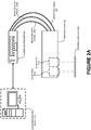
- Figure 2A is a schematic diagram of a laser system comprising a data processing device 200 coupled to a laser controller 202, which in turn is coupled to the marking head 102, according to one or more embodiments.
- the data processing device 200 may be communicatively coupled (e.g., via a wired data connection and/or a wireless data connection) to the laser controller 202. Furthermore, the wireless data connection may be facilitated through the use of a cloud network, which may comprise a cloud server to handle cloud computing (e.g., transmitting data signal(s) to the laser controller 202 through the World Wide Web) as necessary.
- the data processing device 200 may transmit a data signal to the laser controller 202 based on a user input.
- the laser controller 202 may convert the data signal into digital input signals that are transmitted to the marking head 102 via an interface cable 206. The transmission of data may follow a particular protocol.
- the digital input signals may comprise a set of values for the X axis and/or Y axis for the position of a mirror of a galvanometer scanner.
- This type of data transmission is according to the XY2-100 protocol.
- the position of the galvanometer scanners may then be altered based on the values for the X and/or Y axes.
- the beams are delivered from the laser controller 202 to the marking head 102, specifically into the beam collimators 108A-B.
- beam collimator 108A directs a beam to a reflector 110A that reflects the beam onto the mirrors of the galvanometers scanners in the scan head 100A.
- beam collimator 108B delivers a separate beam to a reflector 110B that reflects the beam onto the mirrors of the galvanometer scanners in the scan head 100B.
- One pair of galvanometer scanners may steer, through the mirrors, a beam to be focused onto a marking surface 208A.
- the two beams are steered at approximately the same time such that they come in contact with the marking surface 208A at around the same time. This may allow the beams to collectively mark the marking surface 208A.
- the collective marking by the two beams is such that the marking surface 208A is marked by both beams at approximately the same time.
- the collective marking by the two beams may be according to one of two laser beam steering modes.
- the input data provided by the data processing device 200 may determine the specific laser beam steering mode to be employed.
- the digital input signals generated by the laser controller 202 may be based on a laser beam steering mode.
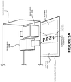
- the mark created is a result of the convergence of the two laser beams at a convergence point 310 on a marking surface 308, as shown in Figure 3A . Accordingly, a single mark may be generated in an overlap area 306 of a marking area 304A and a marking area 304B.
- the marking area 304A may be the area of the marking surface 308 where the laser beam steered by scan head 300A of a marking head 302 can mark the marking surface 308.
- the marking area 304B may be the area of the marking surface 308 where the laser beam steered by scan head 300B of the marking head 302 can mark the marking surface 308.
- the convergence point 310 may be located within the overlap area 306.
- the laser beams may be steered through the scan heads 300A-B such that they converge at the convergence point 310. Subsequently, the laser beams may collectively mark the marking surface 308.
- Figure 3A depicts the convergence of the two laser beams at the convergence point 310.
- the two laser beams are collectively marking the marking surface 308 to create a mark that reads "1234".
- the two laser beams converge within the overlap area 306 in order to mark "1234" on the marking surface 308.
- the two beams are shown converging on the "2".
- the convergence of the two laser beams may assist in the generation of a deeper mark than that generated by a single laser beam.
- a mark such as that created in the preferred embodiment of Figure 3A may be approximately 200 ⁇ m deep, whereas a mark created by a single laser beam may only be 100 ⁇ m deep.
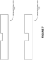
- Figure 7 illustratively demonstrates the differences in depth between two marks as seen through a cross-sectional view of the marks.
- the convergence of the two laser beams may be useful to create a single mark in less time than that which would be created with a single laser.
- the mark created in Figure 3A may be completed in 0.025 seconds, whereas a mark created by a single laser beam may take 0.075 seconds to complete.
- the two laser beams are steered such that each marks a different location of the marking surface.
- FIG 3B illustrates one embodiment of the second laser beam steering mode.
- the two laser beams are collectively marking the marking surface 308, but each laser beam is marking a different location of the marking surface 308 and is ultimately creating a mark that is unique from the mark created by the other laser beam.
- the laser beam steered by scan head 300A of a marking head 302 marked a "1" on the marking surface 308, and the laser beam steered by scan head 300B of the marking head 302 marked a "4" on the marking surface 308.
- Figure 3B displays the two laser beams marking a "2" and a "3" separately on the marking surface 308.
- the laser beam steered by scan head 300A is marking the "2”
- the laser beam steered by scan head 300B is marking the "3.”
- each laser beam is creating two distinct marks: a "1 2" mark and a "3 4" mark.
- the "1 2 3 4" mark may also be considered to be one collective mark in which each laser beam creates a part of the mark, the parts being "1 2" and "3 4".
- the laser beam steering mode may dictate how the mark is to be created. Specifically, it may guide which laser beam will create the first part of the mark and which laser beam will create the second part of the mark. This information may be transmitted from the data processing device to the laser controller in the form of a data signal. The laser controller subsequently may convert the data signal to one or more digital input signals. The digital input signal(s) may configure the galvanometer scanners of the scan heads 300A-B such that when the laser beams are steered, they create one or more marks on the marking surface 308 according to the specified laser beam steering mode. As a result, several parts of the mark to be created are designated to be marked by separate beams or two unique marks are created, each by one laser beam.
- the two laser beams each create the same mark at around the same time.
- the resulting engravings are two identical marks.
- the second laser beam steering mode may result in a configuration of the galvanometer scanners of the scan heads in which a laser beam steered by each scan head creates a mark that reads "ABCD".
- the end product is two separate marks that both read "ABCD" on different locations of the marking surface.
- the laser beams are steered to create two uniquely distinct marks at approximately the same time.
- the first laser beam may be steered to create a mark that reads "DOG”.
- the second laser beam may be steered to create a mark that reads "CAT”. Both marks may be generated at approximately the same time and may be at different locations on the marking surface, but within the marking area of each scan head.
- FIG. 4 is a cross-sectional view of a marking head 402 comprising multiple scan heads 400A-C, according to one or more embodiments.
- Another preferred embodiment of a marking head of a laser marking system may include three or more scan heads.
- the additional scan head(s) may comprise galvanometer scanners that function in the manner that was previously described. Overall, the additional scan head(s) may each steer a laser beam for the creation of a mark separate from that created by the other laser beams.
- Figure 5 portrays a laser marking system in which a laser controller 502 is coupled to three scan heads 500A-C individually via three beam delivery vessels 504A-C.
- scan head 500A is coupled to the laser controller 502 via beam delivery vessel 504A
- scan head 500B is coupled to the laser controller 502 via beam delivery vessel 504B
- scan head 500C is coupled to the laser controller 502 via beam delivery vessel 504C.
- the scan heads 500A-C are arranged over different locations of a marking surface 506 so that the mark(s) may be created at each location at around the same time.
- each laser beam may differ in one or more characteristics from the other laser beam(s).
- the first laser beam may differ in power level, pulse width, focal length, and/or wavelength from that of the second laser beam.
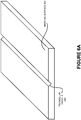
- the difference in beam characteristics may be utilized to create different types of marks on differing surfaces. For instance, a mark may have a triangular profile 600 (as shown in Figure 6A ) on a marking surface 602.
- a mark may have a rectangular profile 604 (as shown in Figure 6B ) on a marking surface 606.
- a marking surface 208B with disparate elevation across its surface may require the use of lasers beam of differing focal lengths.
- the laser beam steered by scan head 100B may be of a greater focal length than that of the laser beam steered by scan head 100A.
- various beam characteristics may be responsible for the disparate marking profiles and focal lengths.
- the beams may differ in characteristics that affect the width of the mark.
- One laser beam may create a mark that is wider or less wide than a mark created by another laser beam generated by the same laser controller.
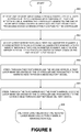
- FIG. 8 is a process flow diagram listing the steps for marking a surface with two laser beams at approximately the same time, according to one or more embodiments.
- Operation 800 discusses receiving one or more input signals from a controller of a laser system coupled to a marking head through an interface cable, wherein the controller generates the input signal(s) based on input data received from a data processing device communicatively coupled to the controller.
- Operation 802 discusses adjusting a first mirror through a first galvanometer scanner, a second mirror through a second galvanometer scanner, a third mirror through a third galvanometer scanner, and a fourth mirror through a fourth galvanometer scanner based on the one or more input signals.
- Operation 804 discusses steering, through the first mirror and the second mirror, a first laser beam generated by the controller and transmitted to the marking head through a beam delivery vessel.
- Operation 806 discusses steering through the third mirror and the fourth mirror, a second laser beam generated by the controller and transmitted to the marking head through another beam delivery vessel.
- Operation 808 discloses the outcome of the process discussed in operations 800-806.
- the structures and modules in the figures may be shown as distinct and communicating with only a few specific structures and not others.
- the structures may be merged with each other, may perform overlapping functions, and may communicate with other structures not shown to be connected in the figures. Accordingly, the specification and/or drawings may be regarded in an illustrative rather than a restrictive sense.
Landscapes
- Laser Beam Processing (AREA)
Description
- This application is a non-provisional application and claims priority to:
- 1)
U.S. Provisional Patent Application No. 61/807,238 - 2)
U.S. Non-Provisional Patent Application No. 14/097,273 - This disclosure relates generally to laser marking systems and, more particularly, to a method, system, and/or apparatus for the collective marking of a surface by two or more laser beams generated by a laser controller.
- Presently, most laser marking devices utilize a single scan head in order to carry out tasks such as the marking of objects. The utilization of a single scan head for marking an object may consume an inordinate amount of time during a single production cycle. For production cycles that require a shorter marking time, laser systems with a single scan head may not be ideal. Furthermore, purchasing additional laser marking devices to shorten the cycle time may not be cost effective. If multiple laser marking devices are used, coordinating the devices may be a difficult process and may not be error-free. Further yet, current systems that use multiple scan heads may not provide a facility to modify individual laser beam characteristics (e.g. pulse duration, pulse energy, wavelength, etc.) to produce unique marking depths, marking profiles, and/or marks that differ from one another. Additionally, systems that use multiple scan heads may not provide the facility to converge multiple laser beams to generate a deeper mark and/or a mark with a unique profile in less time than it would take a single laser beam.
Patent document EP 1 990 124 A1 , discloses a multi-laser printing system having a single scan lens. - Disclosed are a method, system, and/or apparatus for the collective marking of a surface by two or more laser beams generated by a laser controller.
- In one aspect, a method of a marking head of a laser system comprises receiving one or more input signals from a controller of the laser system coupled to the marking head through at least one interface cable, wherein the controller generates the one or more input signals based on input data received from a data processing device communicatively coupled to the controller. The method further comprises adjusting a first mirror through a first galvanometer scanner, a second mirror through a second galvanometer scanner, a third mirror through a third galvanometer scanner, and a fourth mirror through a fourth galvanometer scanner based on the one or more input signals.
- In addition, the method involves steering, through the first mirror and the second mirror, a first laser beam generated by the controller and transmitted to the marking head through a beam delivery vessel and steering, through the third mirror and the fourth mirror, a second laser beam generated by the controller and transmitted to the marking head through another beam delivery vessel. The first galvanometer scanner, the second galvanometer scanner, the third galvanometer scanner, and the fourth galvanometer scanner are configured by the one or more input signals to steer the first laser beam and the second laser beam such that the first laser beam and the second laser beam collectively mark a marking surface.
- In another aspect, a laser marking system to mark a marking surface comprises a controller, a data processing device communicatively coupled to the controller, and a marking head coupled to the controller through at least one interface cable. The marking head further comprises a first mirror of a first galvanometer scanner, a second mirror of a second galvanometer scanner, a third mirror of a third galvanometer scanner, and a fourth mirror of a fourth galvanometer scanner.
- In particular, the marking head is configured to receive one or more input signals from the controller, wherein the controller generates the one or more input signals based on input data received from the data processing device. The marking head is additionally configured to adjust the first mirror through the first galvanometer scanner, the second mirror through the second galvanometer scanner, the third mirror through the third galvanometer scanner, and the fourth mirror through the fourth galvanometer scanner based on one or more input signals. The marking head is also configured to steer, through the first mirror and the second mirror, a first laser beam generated by the controller and transmitted to the marking head through a beam delivery vessel and, through the third mirror and the fourth mirror, a second laser beam generated by the controller and transmitted to the marking head through another beam delivery vessel.
- The first galvanometer scanner, the second galvanometer scanner, the third galvanometer scanner, and the fourth galvanometer scanner are configured by the one or more input signals to steer the first laser beam and the second laser beam such that the first laser beam and the second laser beam collectively mark the marking surface.
- The input data received from the data processing device comprises data instructing the controller to configure the one or more input signals based on a laser beam steering mode, wherein the laser beam steering mode involves the generation of a mark made through a convergence of the first laser beam and the second laser beam at a convergence point on the marking surface and/or two marks made at around the same time, wherein one mark is created by the first laser beam and another mark is created by the second laser beam. In particular, the convergence point lies within an area of overlap, wherein the area of overlap is a region on the marking surface where both the first laser beam and the second laser beam can be steered to mark the marking surface.
- The methods and systems disclosed herein may be implemented in any means for achieving various aspects, and may be executed in a form of a non-transitory machine-readable medium embodying a set of instructions that, when executed by a machine, cause the machine to perform any of the operations disclosed herein. Other features will be apparent from the accompanying drawings and from the detailed description that follows.
- The embodiments of this invention are illustrated by way of example and not limitation in the figures of the accompanying drawings, in which like references indicate similar elements and in which:
-
Figure 1 illustrates a marking head of a laser system comprising two scan heads for the independent steering of two laser beams, according to one or more embodiments. -
Figure 2A is a schematic diagram of a laser system comprising a data processing device coupled to a laser controller, which in turn is communicatively coupled to a marking head, according to one or more embodiments. -
Figure 2B is a view of the marking head ofFigure 2A , depicting a variable marking surface to be marked with beams of differing focal lengths, according to one or more embodiments. -
Figure 3A is a cross-sectional view of a marking head comprising two scan heads that steer two laser beams that converge on a point of the marking surface, according to one or more embodiments. -
Figure 3B is a cross-sectional view of the marking head comprising two scan heads that steer two laser beams that mark a marking surface at different location with disparate marks, according to one or more embodiments. -
Figure 4 is a cross-sectional view of a marking head comprising multiple scan heads, according to one or more embodiments. -
Figure 5 is a schematic diagram of a laser controller coupled to multiple scan heads of one or more marking head for the marking of different areas of a marking surface, according to one or more embodiments. -
Figure 6A is a perspective view of a marking surface, specifically depicting a marking with a triangular profile, according to one or more embodiments. -
Figure 6B is a perspective view of a marking surface, portraying a marking with a rectangular profile, according to one or more embodiments. -
Figure 7 illustrates two cross-sectional views of a marking surface in which one mark is of a greater depth than the other mark, according to one or more embodiments. -
Figure 8 is a process flow diagram listing the steps for marking a surface with two laser beams at approximately the same time, according to one or more embodiments. - Other features of the present embodiments will be apparent from the accompanying drawings and from the detailed description that follows.
- Disclosed are methods, systems, and/or apparatus for the collective marking of a surface by two or more laser beams generated by a laser controller. Although the present embodiments have been described with reference to specific example embodiments, it will be evident that various modifications and changes may be made to these embodiments without departing from the broader spirit and scope of the various embodiments. Moreover the components shown in the figures, their connections, couplings, relationships, and functions are meant to be exemplary only and are not meant to limit or restrict the embodiments described herein. The following terms should be understood by one of ordinary skill in the art as industry terms: "laser beam(s)," "steering," "marking head," "scan head," "galvanometer scanner," "beam collimation/collimator(s)," and "marking on the fly." These terms are used according to their industry definitions, unless specified otherwise.
- For the purpose of this disclosure, a "mark" is created by a laser marking system. The mark may be an engraving. Alternatively, the mark may be created through an annealing process or through any other material processing methods.
- To explicate what a mark may constitute, an engraved mark is employed in the following example. A mark may collectively describe the character(s) that are engraved onto a surface at one time. For example, an entire engraving of a vehicle identification number (VIN) that consists of 17 characters may be designated as a mark. Each individual character is one part of the mark. Furthermore, a mark may also describe an image or images that are engraved onto a surface. In other instances, a mark may describe the specific engraving created by a single laser beam. If two laser beams are deployed to engrave a VIN such that one laser beam engraves the first 8 characters of the VIN while the second laser beam engraves the last 9 characters of the VIN, each set of characters engraved by each individual laser beam may be designated as a mark.
- A laser marking system may be utilized to mark surfaces with information such as manufacturers' names, part numbers, model numbers, etc. However, when this process is accomplished on an assembly line, there is a need for quick, efficient, and accurate marking of objects. The utilization of a laser system with a single laser in such a situation may not be adequate for reaching production goals or quotas. Under these or other circumstances, a laser system with multiple lasers (e.g., two or more lasers) may expedite the marking process. An embodiment of such a laser system is depicted in
Figure 1 . - In particular,
Figure 1 illustrates a markinghead 102 of a laser system comprising two scan heads 100A-B for the independent steering of two laser beams, according to one or more embodiments. In addition to the scan heads 100A-B, the markinghead 102 may house twobeam collimators 108A-B; twointegrated circuit boards 106A-B; and/or tworeflectors 110A-B.Figure 1 illustrates a preferred embodiment of the arrangement of the above listed components of the markinghead 102; however, different arrangements are within the scope of this exemplary embodiment. - The exemplary embodiment described herein may be utilized for marking stationary objects and/or moving objects. The marking of moving objects (e.g., marking on the fly) may be accomplished through the use of additional encoded signals that provide information to the laser system regarding a speed of the moving objects.
- The scan heads 100A-B may be pre-manufactured scan heads utilized in the industry, such as the SCANcube® 10. The scan heads 100A-B may each further comprise multiple galvanometer scanners (not shown). Attached to a galvanometer scanner may be a mirror (not shown). The use of two galvanometer scanners per scan head enables the deflection of a beam off of each mirror and the subsequent focusing of the beam through a scan lens (e.g., F-Theta objective) of the scan head. The mirrors may be tiltable such that the deflection angles can be adjusted based on the positions of the galvanometer scanners.
- Prior to the reflection of the laser beams off of the
reflectors 110A-B, the laser beams may be delivered to thebeam collimators 108A-B through two separatebeam delivery vessels 104A-B, where the beams are conditioned and focused according to predetermined values. Thebeam delivery vessels 104A-B may be coupled to thebeam collimators 108A-B at one end and to alaser controller 202 at the other end, as depicted inFigure 2A . Specifically,Figure 2A is a schematic diagram of a laser system comprising a data processing device 200 coupled to alaser controller 202, which in turn is coupled to the markinghead 102, according to one or more embodiments. - The data processing device 200 may be communicatively coupled (e.g., via a wired data connection and/or a wireless data connection) to the
laser controller 202. Furthermore, the wireless data connection may be facilitated through the use of a cloud network, which may comprise a cloud server to handle cloud computing (e.g., transmitting data signal(s) to thelaser controller 202 through the World Wide Web) as necessary. The data processing device 200 may transmit a data signal to thelaser controller 202 based on a user input. Thelaser controller 202 may convert the data signal into digital input signals that are transmitted to the markinghead 102 via aninterface cable 206. The transmission of data may follow a particular protocol. For example, the digital input signals may comprise a set of values for the X axis and/or Y axis for the position of a mirror of a galvanometer scanner. This type of data transmission is according to the XY2-100 protocol. The position of the galvanometer scanners may then be altered based on the values for the X and/or Y axes. - Concurrent with or at a different time than the transmission of the digital input signals, the beams are delivered from the
laser controller 202 to the markinghead 102, specifically into thebeam collimators 108A-B. Subsequently,beam collimator 108A directs a beam to areflector 110A that reflects the beam onto the mirrors of the galvanometers scanners in thescan head 100A. Similarly,beam collimator 108B delivers a separate beam to areflector 110B that reflects the beam onto the mirrors of the galvanometer scanners in thescan head 100B. - One pair of galvanometer scanners may steer, through the mirrors, a beam to be focused onto a marking
surface 208A. In a preferred embodiment, the two beams are steered at approximately the same time such that they come in contact with the markingsurface 208A at around the same time. This may allow the beams to collectively mark the markingsurface 208A. In one exemplary embodiment, the collective marking by the two beams is such that the markingsurface 208A is marked by both beams at approximately the same time. - According to one or more embodiments, the collective marking by the two beams may be according to one of two laser beam steering modes. The input data provided by the data processing device 200 may determine the specific laser beam steering mode to be employed. In particular, the digital input signals generated by the
laser controller 202 may be based on a laser beam steering mode. According to one laser beam steering mode, the mark created is a result of the convergence of the two laser beams at aconvergence point 310 on a markingsurface 308, as shown inFigure 3A . Accordingly, a single mark may be generated in anoverlap area 306 of a marking area 304A and amarking area 304B. Specifically, the marking area 304A may be the area of the markingsurface 308 where the laser beam steered byscan head 300A of a markinghead 302 can mark the markingsurface 308. Analogously, the markingarea 304B may be the area of the markingsurface 308 where the laser beam steered byscan head 300B of the markinghead 302 can mark the markingsurface 308. - According to one or more embodiments, the
convergence point 310 may be located within theoverlap area 306. The laser beams may be steered through the scan heads 300A-B such that they converge at theconvergence point 310. Subsequently, the laser beams may collectively mark the markingsurface 308. Reference is now made toFigure 3A , which depicts the convergence of the two laser beams at theconvergence point 310. In particular, the two laser beams are collectively marking the markingsurface 308 to create a mark that reads "1234". The two laser beams converge within theoverlap area 306 in order to mark "1234" on the markingsurface 308. - In the embodiment illustrated in
Figure 3A , the two beams are shown converging on the "2". The convergence of the two laser beams may assist in the generation of a deeper mark than that generated by a single laser beam. For example, a mark such as that created in the preferred embodiment ofFigure 3A may be approximately 200 µm deep, whereas a mark created by a single laser beam may only be 100 µm deep.Figure 7 illustratively demonstrates the differences in depth between two marks as seen through a cross-sectional view of the marks. In addition, the convergence of the two laser beams may be useful to create a single mark in less time than that which would be created with a single laser. For example, the mark created inFigure 3A may be completed in 0.025 seconds, whereas a mark created by a single laser beam may take 0.075 seconds to complete. - According to a second laser beam steering mode, the two laser beams are steered such that each marks a different location of the marking surface. Reference is now made to
Figure 3B which illustrates one embodiment of the second laser beam steering mode. InFigure 3B , the two laser beams are collectively marking the markingsurface 308, but each laser beam is marking a different location of the markingsurface 308 and is ultimately creating a mark that is unique from the mark created by the other laser beam. For example, as shown inFigure 3B , the laser beam steered byscan head 300A of a markinghead 302 marked a "1" on the markingsurface 308, and the laser beam steered byscan head 300B of the markinghead 302 marked a "4" on the markingsurface 308.Figure 3B displays the two laser beams marking a "2" and a "3" separately on the markingsurface 308. In particular, the laser beam steered byscan head 300A is marking the "2," and the laser beam steered byscan head 300B is marking the "3." In essence, each laser beam is creating two distinct marks: a "1 2" mark and a "3 4" mark. However, the "1 2 3 4" mark may also be considered to be one collective mark in which each laser beam creates a part of the mark, the parts being "1 2" and "3 4". - The laser beam steering mode may dictate how the mark is to be created. Specifically, it may guide which laser beam will create the first part of the mark and which laser beam will create the second part of the mark. This information may be transmitted from the data processing device to the laser controller in the form of a data signal. The laser controller subsequently may convert the data signal to one or more digital input signals. The digital input signal(s) may configure the galvanometer scanners of the scan heads 300A-B such that when the laser beams are steered, they create one or more marks on the marking
surface 308 according to the specified laser beam steering mode. As a result, several parts of the mark to be created are designated to be marked by separate beams or two unique marks are created, each by one laser beam. - In an alternative embodiment of the second laser beam steering mode, the two laser beams each create the same mark at around the same time. The resulting engravings are two identical marks. For example, the second laser beam steering mode may result in a configuration of the galvanometer scanners of the scan heads in which a laser beam steered by each scan head creates a mark that reads "ABCD". Thus, the end product is two separate marks that both read "ABCD" on different locations of the marking surface.
- In yet another alternative embodiment of the second laser beam steering mode, the laser beams are steered to create two uniquely distinct marks at approximately the same time. For example, the first laser beam may be steered to create a mark that reads "DOG". The second laser beam may be steered to create a mark that reads "CAT". Both marks may be generated at approximately the same time and may be at different locations on the marking surface, but within the marking area of each scan head.
- Reference is now made to
Figure 4 , which is a cross-sectional view of a markinghead 402 comprising multiple scan heads 400A-C, according to one or more embodiments. Another preferred embodiment of a marking head of a laser marking system may include three or more scan heads. The additional scan head(s) may comprise galvanometer scanners that function in the manner that was previously described. Overall, the additional scan head(s) may each steer a laser beam for the creation of a mark separate from that created by the other laser beams. - The arrangement of the scan heads 400A-C depicted in
Figure 4 is an exemplary embodiment. However, other positional arrangements and number of scan heads are within the scope of this exemplary embodiment. An illustration of another arrangement of multiple scan heads of a laser marking systems can be seen inFigure 5 . For example,Figure 5 portrays a laser marking system in which alaser controller 502 is coupled to three scan heads 500A-C individually via threebeam delivery vessels 504A-C. Specifically, scanhead 500A is coupled to thelaser controller 502 viabeam delivery vessel 504A; scanhead 500B is coupled to thelaser controller 502 via beam delivery vessel 504B; and scanhead 500C is coupled to thelaser controller 502 viabeam delivery vessel 504C. The scan heads 500A-C are arranged over different locations of a markingsurface 506 so that the mark(s) may be created at each location at around the same time. - The exemplary embodiments disclosed herein provide for a method, system, and/or device for the collective marking of a surface by two or more laser beams generated by a laser controller. Apart from the differences in the marks that each laser beam may create, each laser beam may differ in one or more characteristics from the other laser beam(s). For example, in a laser marking system with two scan heads, two laser beams are independently steered by the scan heads. The first laser beam may differ in power level, pulse width, focal length, and/or wavelength from that of the second laser beam. The difference in beam characteristics may be utilized to create different types of marks on differing surfaces. For instance, a mark may have a triangular profile 600 (as shown in
Figure 6A ) on a markingsurface 602. Alternatively, a mark may have a rectangular profile 604 (as shown inFigure 6B ) on a markingsurface 606. In another example, as depicted inFigure 2B , a markingsurface 208B with disparate elevation across its surface may require the use of lasers beam of differing focal lengths. The laser beam steered byscan head 100B may be of a greater focal length than that of the laser beam steered byscan head 100A. Overall, various beam characteristics may be responsible for the disparate marking profiles and focal lengths. In addition, the beams may differ in characteristics that affect the width of the mark. One laser beam may create a mark that is wider or less wide than a mark created by another laser beam generated by the same laser controller. -
Figure 8 is a process flow diagram listing the steps for marking a surface with two laser beams at approximately the same time, according to one or more embodiments.Operation 800 discusses receiving one or more input signals from a controller of a laser system coupled to a marking head through an interface cable, wherein the controller generates the input signal(s) based on input data received from a data processing device communicatively coupled to the controller.Operation 802 discusses adjusting a first mirror through a first galvanometer scanner, a second mirror through a second galvanometer scanner, a third mirror through a third galvanometer scanner, and a fourth mirror through a fourth galvanometer scanner based on the one or more input signals.Operation 804 discusses steering, through the first mirror and the second mirror, a first laser beam generated by the controller and transmitted to the marking head through a beam delivery vessel.Operation 806 discusses steering through the third mirror and the fourth mirror, a second laser beam generated by the controller and transmitted to the marking head through another beam delivery vessel.Operation 808 discloses the outcome of the process discussed in operations 800-806. - In addition, it will be appreciated that the various operations, processes and methods disclosed herein may be embodied in a non-transitory machine-readable medium and/or a machine-accessible medium compatible with a data processing system (e.g., data processing device 200). Accordingly, the specification and drawings are to be regarded in an illustrative rather than a restrictive sense.
- The structures and modules in the figures may be shown as distinct and communicating with only a few specific structures and not others. The structures may be merged with each other, may perform overlapping functions, and may communicate with other structures not shown to be connected in the figures. Accordingly, the specification and/or drawings may be regarded in an illustrative rather than a restrictive sense.
Claims (8)
- A method of a marking head of a laser system, comprising:receiving one or more input signals from a controller (202) of the laser system coupled to the marking head (102) through at least one interface cable (206), wherein the controller (202) generates the one or more input signals based on input data received from a data processing device (200) communicatively coupled to the controller (202);adjusting a first mirror through a first galvanometer scanner, a second mirror through a second galvanometer scanner, a third mirror through a third galvanometer scanner, and a fourth mirror through a fourth galvanometer scanner based on the one or more input signals;steering, through the first mirror and the second mirror, a first laser beam generated by the controller (202) and transmitted to the marking head (102) through a beam delivery vessel (104A); andsteering, through the third mirror and the fourth mirror, a second laser beam generated by the controller (202) and transmitted to the marking head (102) through another beam delivery vessel (104B),wherein the first laser beam is focused through a first scan lens and wherein the second laser beam is focused through a second scan lens, and
wherein the first galvanometer scanner, the second galvanometer scanner, the third galvanometer scanner, and the fourth galvanometer scanner are, in a first mode, configured by the one or more input signals to steer the first laser beam and the second laser beam such that the first laser beam and the second laser beam converge at a convergence point (310) on a marking surface (308) to mark the marking surface. - The method of claim 1, wherein the first galvanometer scanner, the second galvanometer scanner, the third galvanometer scanner, and the fourth galvanometer scanner are, in a second mode, configured by the one or more input signals to steer the first laser beam and the second laser beam such that the first laser beam and the second laser beam make two marks at the same time, wherein one mark is created by the first laser beam and another mark is created by the second laser beam.
- The method of claim 2, wherein the two marks are unique markings distinct from one another.
- The method of claim 2, wherein the two marks are equivalent marks.
- The method of claim 1:wherein the marking head (102) steers, through one or more additional mirrors, one or more additional laser beams generated by the controller (502), andwherein the one or more additional mirrors are adjusted by one or more additional galvanometer scanners.
- The method of any preceding claim, wherein the first laser beam and the second laser beam differ in at least one characteristic, wherein the at least one characteristic is at least one of a power level, a pulse width, a focal length and a wavelength.
- A laser marking system to mark a marking surface (208A, 208B), comprising:a controller (202);a data processing device (200) communicatively coupled to the controller (202);a marking head (102) coupled to the controller (202) through at least one interface cable (206),wherein the marking head (102) further comprises:a first mirror of a first galvanometer scanner,a second mirror of a second galvanometer scanner, a third mirror of a third galvanometer scanner, anda fourth mirror of a fourth galvanometer scanner;wherein the laser marking system is configured to perform the method of any of claims 1 to 6.
- A non-transitory medium, readable through a processor of a data processing device (200), the data processing device (200) communicatively coupled to a controller (202) of a laser marking device according to claim 7, said medium including instructions embodied therein that are executable through the processor to cause performance of the method of any of claims 1 to 6.
Applications Claiming Priority (3)
| Application Number | Priority Date | Filing Date | Title |
|---|---|---|---|
| US201361807238P | 2013-04-01 | 2013-04-01 | |
| US14/097,273 US8854406B1 (en) | 2013-04-01 | 2013-12-05 | Collective marking of a surface by steering multiple laser beams generated by a laser controller |
| PCT/US2014/031382 WO2014165332A1 (en) | 2013-04-01 | 2014-03-21 | Collective marking of a surface by steering multiple laser beams generated by a laser controller |
Publications (3)
| Publication Number | Publication Date |
|---|---|
| EP2981388A1 EP2981388A1 (en) | 2016-02-10 |
| EP2981388A4 EP2981388A4 (en) | 2016-08-24 |
| EP2981388B1 true EP2981388B1 (en) | 2018-01-10 |
Family
ID=51620446
Family Applications (1)
| Application Number | Title | Priority Date | Filing Date |
|---|---|---|---|
| EP14778251.0A Active EP2981388B1 (en) | 2013-04-01 | 2014-03-21 | Collective marking of a surface by steering multiple laser beams generated by a laser controller |
Country Status (3)
| Country | Link |
|---|---|
| US (1) | US8854406B1 (en) |
| EP (1) | EP2981388B1 (en) |
| WO (1) | WO2014165332A1 (en) |
Families Citing this family (3)
| Publication number | Priority date | Publication date | Assignee | Title |
|---|---|---|---|---|
| CN104999814B (en) * | 2015-07-28 | 2017-08-01 | 深圳泰德激光科技有限公司 | Laser marking control method and galvanometer type laser marking system |
| US10513400B1 (en) | 2018-05-31 | 2019-12-24 | Ashot Mesropyan | Method and system of real-time analysis and marking of a target surface using a digital camera coupled marking device |
| GB201913631D0 (en) * | 2019-09-20 | 2019-11-06 | Alltec Angewandte Laserlicht Tech Gesellschaft Mit Beschraenkter Haftung | Electromagnetic radiation system |
Family Cites Families (13)
| Publication number | Priority date | Publication date | Assignee | Title |
|---|---|---|---|---|
| JP2755400B2 (en) * | 1988-11-15 | 1998-05-20 | シチズン時計株式会社 | Drawing equipment |
| JP2559947B2 (en) * | 1992-05-26 | 1996-12-04 | 新日本製鐵株式会社 | Dimple processing apparatus and processing method for cooling drum for casting thin wall slab |
| US5521628A (en) * | 1993-08-30 | 1996-05-28 | Lumonics Corporation | Laser system for simultaneously marking multiple parts |
| US5855969A (en) * | 1996-06-10 | 1999-01-05 | Infosight Corp. | CO2 laser marking of coated surfaces for product identification |
| US6064034A (en) * | 1996-11-22 | 2000-05-16 | Anolaze Corporation | Laser marking process for vitrification of bricks and other vitrescent objects |
| KR100691924B1 (en) * | 1999-04-27 | 2007-03-09 | 지에스아이 루모닉스 인코퍼레이티드 | Material processing apparatus and method |
| JP4006153B2 (en) | 1999-12-14 | 2007-11-14 | キヤノン株式会社 | Multi-beam optical scanning optical system and image forming apparatus using the same |
| US20030024913A1 (en) * | 2002-04-15 | 2003-02-06 | Downes Joseph P. | Laser scanning method and system for marking articles such as printed circuit boards, integrated circuits and the like |
| JP3855684B2 (en) * | 2001-06-05 | 2006-12-13 | 松下電器産業株式会社 | Laser processing apparatus and laser processing method |
| JP4480075B2 (en) | 2004-09-16 | 2010-06-16 | 株式会社リコー | Optical writing apparatus and image forming apparatus |
| JP4566723B2 (en) | 2004-12-08 | 2010-10-20 | キヤノン株式会社 | Laser scanner and image forming apparatus using the same |
| KR100864863B1 (en) * | 2007-05-09 | 2008-10-23 | 주식회사 이오테크닉스 | Multi laser system |
| JP2010107561A (en) | 2008-10-28 | 2010-05-13 | Ricoh Co Ltd | Optical scanner unit and image forming apparatus |
-
2013
- 2013-12-05 US US14/097,273 patent/US8854406B1/en active Active
-
2014
- 2014-03-21 WO PCT/US2014/031382 patent/WO2014165332A1/en not_active Ceased
- 2014-03-21 EP EP14778251.0A patent/EP2981388B1/en active Active
Non-Patent Citations (1)
| Title |
|---|
| None * |
Also Published As
| Publication number | Publication date |
|---|---|
| US20140292994A1 (en) | 2014-10-02 |
| US8854406B1 (en) | 2014-10-07 |
| EP2981388A4 (en) | 2016-08-24 |
| EP2981388A1 (en) | 2016-02-10 |
| WO2014165332A1 (en) | 2014-10-09 |
Similar Documents
| Publication | Publication Date | Title |
|---|---|---|
| DE102018218033B4 (en) | Laser processing system | |
| DE102018209546A1 (en) | LASER PROCESSING ROBOT SYSTEM | |
| EP1031396A1 (en) | Laser processing apparatus and method | |
| US8854406B1 (en) | Collective marking of a surface by steering multiple laser beams generated by a laser controller | |
| EP3124163B1 (en) | System and method for laser processing | |
| CN204771159U (en) | Laser machining device | |
| KR102483670B1 (en) | Laser machining system and laser machining method | |
| CN1754694B (en) | Pattern plate making method and apparatus | |
| KR20180118143A (en) | Position of image plane in laser machining system | |
| JP2002542043A (en) | Material processing system and method using multiple laser beams | |
| EP2844418B1 (en) | A method for making laser engravures on a paper web | |
| JP2000042779A (en) | Laser beam machining device | |
| DE112008003863B4 (en) | Method for generating a drive pattern for a galvano scanner system | |
| JP4800939B2 (en) | Laser processing apparatus, program creation apparatus, and laser processing method | |
| JP6621128B2 (en) | Intensive marking on surfaces by manipulating multiple laser beams generated by a laser controller | |
| JP2003048093A (en) | Laser processing apparatus and processing method thereof | |
| JP5121744B2 (en) | Plate making apparatus and plate making method | |
| CN117680830A (en) | Laser flight marking method and device, electronic equipment and storage medium | |
| JP3237832B2 (en) | Laser processing apparatus and laser drilling method | |
| JP2002224865A (en) | Laser beam marking device | |
| CN205416765U (en) | Laser marking auto focus device | |
| US10350706B2 (en) | Laser processing system and recording medium storing computer readable programs for controlling the same | |
| JP2004105971A (en) | Laser beam welding apparatus | |
| KR20020086344A (en) | Time-sharing laser marking device with selectable multiple scan-heads and method the same | |
| JP7380333B2 (en) | Laser processing equipment and processing method |
Legal Events
| Date | Code | Title | Description |
|---|---|---|---|
| PUAI | Public reference made under article 153(3) epc to a published international application that has entered the european phase |
Free format text: ORIGINAL CODE: 0009012 |
|
| 17P | Request for examination filed |
Effective date: 20150625 |
|
| AK | Designated contracting states |
Kind code of ref document: A1 Designated state(s): AL AT BE BG CH CY CZ DE DK EE ES FI FR GB GR HR HU IE IS IT LI LT LU LV MC MK MT NL NO PL PT RO RS SE SI SK SM TR |
|
| AX | Request for extension of the european patent |
Extension state: BA ME |
|
| DAX | Request for extension of the european patent (deleted) | ||
| A4 | Supplementary search report drawn up and despatched |
Effective date: 20160727 |
|
| RIC1 | Information provided on ipc code assigned before grant |
Ipc: B23K 26/064 20140101ALI20160721BHEP Ipc: B23K 26/18 20060101AFI20160721BHEP Ipc: B41J 2/47 20060101ALI20160721BHEP |
|
| GRAP | Despatch of communication of intention to grant a patent |
Free format text: ORIGINAL CODE: EPIDOSNIGR1 |
|
| STAA | Information on the status of an ep patent application or granted ep patent |
Free format text: STATUS: GRANT OF PATENT IS INTENDED |
|
| INTG | Intention to grant announced |
Effective date: 20170724 |
|
| GRAS | Grant fee paid |
Free format text: ORIGINAL CODE: EPIDOSNIGR3 |
|
| GRAA | (expected) grant |
Free format text: ORIGINAL CODE: 0009210 |
|
| STAA | Information on the status of an ep patent application or granted ep patent |
Free format text: STATUS: THE PATENT HAS BEEN GRANTED |
|
| AK | Designated contracting states |
Kind code of ref document: B1 Designated state(s): AL AT BE BG CH CY CZ DE DK EE ES FI FR GB GR HR HU IE IS IT LI LT LU LV MC MK MT NL NO PL PT RO RS SE SI SK SM TR |
|
| REG | Reference to a national code |
Ref country code: CH Ref legal event code: EP Ref country code: AT Ref legal event code: REF Ref document number: 961863 Country of ref document: AT Kind code of ref document: T Effective date: 20180115 |
|
| REG | Reference to a national code |
Ref country code: IE Ref legal event code: FG4D |
|
| REG | Reference to a national code |
Ref country code: DE Ref legal event code: R096 Ref document number: 602014019696 Country of ref document: DE |
|
| REG | Reference to a national code |
Ref country code: NL Ref legal event code: MP Effective date: 20180110 |
|
| REG | Reference to a national code |
Ref country code: AT Ref legal event code: MK05 Ref document number: 961863 Country of ref document: AT Kind code of ref document: T Effective date: 20180110 |
|
| PG25 | Lapsed in a contracting state [announced via postgrant information from national office to epo] |
Ref country code: NL Free format text: LAPSE BECAUSE OF FAILURE TO SUBMIT A TRANSLATION OF THE DESCRIPTION OR TO PAY THE FEE WITHIN THE PRESCRIBED TIME-LIMIT Effective date: 20180110 |
|
| PG25 | Lapsed in a contracting state [announced via postgrant information from national office to epo] |
Ref country code: CY Free format text: LAPSE BECAUSE OF FAILURE TO SUBMIT A TRANSLATION OF THE DESCRIPTION OR TO PAY THE FEE WITHIN THE PRESCRIBED TIME-LIMIT Effective date: 20180110 Ref country code: HR Free format text: LAPSE BECAUSE OF FAILURE TO SUBMIT A TRANSLATION OF THE DESCRIPTION OR TO PAY THE FEE WITHIN THE PRESCRIBED TIME-LIMIT Effective date: 20180110 Ref country code: FI Free format text: LAPSE BECAUSE OF FAILURE TO SUBMIT A TRANSLATION OF THE DESCRIPTION OR TO PAY THE FEE WITHIN THE PRESCRIBED TIME-LIMIT Effective date: 20180110 Ref country code: NO Free format text: LAPSE BECAUSE OF FAILURE TO SUBMIT A TRANSLATION OF THE DESCRIPTION OR TO PAY THE FEE WITHIN THE PRESCRIBED TIME-LIMIT Effective date: 20180410 Ref country code: LT Free format text: LAPSE BECAUSE OF FAILURE TO SUBMIT A TRANSLATION OF THE DESCRIPTION OR TO PAY THE FEE WITHIN THE PRESCRIBED TIME-LIMIT Effective date: 20180110 Ref country code: ES Free format text: LAPSE BECAUSE OF FAILURE TO SUBMIT A TRANSLATION OF THE DESCRIPTION OR TO PAY THE FEE WITHIN THE PRESCRIBED TIME-LIMIT Effective date: 20180110 |
|
| PG25 | Lapsed in a contracting state [announced via postgrant information from national office to epo] |
Ref country code: AT Free format text: LAPSE BECAUSE OF FAILURE TO SUBMIT A TRANSLATION OF THE DESCRIPTION OR TO PAY THE FEE WITHIN THE PRESCRIBED TIME-LIMIT Effective date: 20180110 Ref country code: SE Free format text: LAPSE BECAUSE OF FAILURE TO SUBMIT A TRANSLATION OF THE DESCRIPTION OR TO PAY THE FEE WITHIN THE PRESCRIBED TIME-LIMIT Effective date: 20180110 Ref country code: LV Free format text: LAPSE BECAUSE OF FAILURE TO SUBMIT A TRANSLATION OF THE DESCRIPTION OR TO PAY THE FEE WITHIN THE PRESCRIBED TIME-LIMIT Effective date: 20180110 Ref country code: BG Free format text: LAPSE BECAUSE OF FAILURE TO SUBMIT A TRANSLATION OF THE DESCRIPTION OR TO PAY THE FEE WITHIN THE PRESCRIBED TIME-LIMIT Effective date: 20180410 Ref country code: RS Free format text: LAPSE BECAUSE OF FAILURE TO SUBMIT A TRANSLATION OF THE DESCRIPTION OR TO PAY THE FEE WITHIN THE PRESCRIBED TIME-LIMIT Effective date: 20180110 Ref country code: IS Free format text: LAPSE BECAUSE OF FAILURE TO SUBMIT A TRANSLATION OF THE DESCRIPTION OR TO PAY THE FEE WITHIN THE PRESCRIBED TIME-LIMIT Effective date: 20180510 Ref country code: GR Free format text: LAPSE BECAUSE OF FAILURE TO SUBMIT A TRANSLATION OF THE DESCRIPTION OR TO PAY THE FEE WITHIN THE PRESCRIBED TIME-LIMIT Effective date: 20180411 Ref country code: PL Free format text: LAPSE BECAUSE OF FAILURE TO SUBMIT A TRANSLATION OF THE DESCRIPTION OR TO PAY THE FEE WITHIN THE PRESCRIBED TIME-LIMIT Effective date: 20180110 |
|
| REG | Reference to a national code |
Ref country code: DE Ref legal event code: R097 Ref document number: 602014019696 Country of ref document: DE |
|
| PG25 | Lapsed in a contracting state [announced via postgrant information from national office to epo] |
Ref country code: RO Free format text: LAPSE BECAUSE OF FAILURE TO SUBMIT A TRANSLATION OF THE DESCRIPTION OR TO PAY THE FEE WITHIN THE PRESCRIBED TIME-LIMIT Effective date: 20180110 Ref country code: IT Free format text: LAPSE BECAUSE OF FAILURE TO SUBMIT A TRANSLATION OF THE DESCRIPTION OR TO PAY THE FEE WITHIN THE PRESCRIBED TIME-LIMIT Effective date: 20180110 Ref country code: EE Free format text: LAPSE BECAUSE OF FAILURE TO SUBMIT A TRANSLATION OF THE DESCRIPTION OR TO PAY THE FEE WITHIN THE PRESCRIBED TIME-LIMIT Effective date: 20180110 Ref country code: AL Free format text: LAPSE BECAUSE OF FAILURE TO SUBMIT A TRANSLATION OF THE DESCRIPTION OR TO PAY THE FEE WITHIN THE PRESCRIBED TIME-LIMIT Effective date: 20180110 |
|
| REG | Reference to a national code |
Ref country code: CH Ref legal event code: PL |
|
| PLBE | No opposition filed within time limit |
Free format text: ORIGINAL CODE: 0009261 |
|
| STAA | Information on the status of an ep patent application or granted ep patent |
Free format text: STATUS: NO OPPOSITION FILED WITHIN TIME LIMIT |
|
| PG25 | Lapsed in a contracting state [announced via postgrant information from national office to epo] |
Ref country code: SM Free format text: LAPSE BECAUSE OF FAILURE TO SUBMIT A TRANSLATION OF THE DESCRIPTION OR TO PAY THE FEE WITHIN THE PRESCRIBED TIME-LIMIT Effective date: 20180110 Ref country code: DK Free format text: LAPSE BECAUSE OF FAILURE TO SUBMIT A TRANSLATION OF THE DESCRIPTION OR TO PAY THE FEE WITHIN THE PRESCRIBED TIME-LIMIT Effective date: 20180110 Ref country code: MC Free format text: LAPSE BECAUSE OF FAILURE TO SUBMIT A TRANSLATION OF THE DESCRIPTION OR TO PAY THE FEE WITHIN THE PRESCRIBED TIME-LIMIT Effective date: 20180110 Ref country code: SK Free format text: LAPSE BECAUSE OF FAILURE TO SUBMIT A TRANSLATION OF THE DESCRIPTION OR TO PAY THE FEE WITHIN THE PRESCRIBED TIME-LIMIT Effective date: 20180110 Ref country code: CZ Free format text: LAPSE BECAUSE OF FAILURE TO SUBMIT A TRANSLATION OF THE DESCRIPTION OR TO PAY THE FEE WITHIN THE PRESCRIBED TIME-LIMIT Effective date: 20180110 |
|
| REG | Reference to a national code |
Ref country code: BE Ref legal event code: MM Effective date: 20180331 |
|
| 26N | No opposition filed |
Effective date: 20181011 |
|
| REG | Reference to a national code |
Ref country code: IE Ref legal event code: MM4A |
|
| PG25 | Lapsed in a contracting state [announced via postgrant information from national office to epo] |
Ref country code: LU Free format text: LAPSE BECAUSE OF NON-PAYMENT OF DUE FEES Effective date: 20180321 |
|
| PG25 | Lapsed in a contracting state [announced via postgrant information from national office to epo] |
Ref country code: IE Free format text: LAPSE BECAUSE OF NON-PAYMENT OF DUE FEES Effective date: 20180321 |
|
| PG25 | Lapsed in a contracting state [announced via postgrant information from national office to epo] |
Ref country code: BE Free format text: LAPSE BECAUSE OF NON-PAYMENT OF DUE FEES Effective date: 20180331 Ref country code: CH Free format text: LAPSE BECAUSE OF NON-PAYMENT OF DUE FEES Effective date: 20180331 Ref country code: SI Free format text: LAPSE BECAUSE OF FAILURE TO SUBMIT A TRANSLATION OF THE DESCRIPTION OR TO PAY THE FEE WITHIN THE PRESCRIBED TIME-LIMIT Effective date: 20180110 Ref country code: LI Free format text: LAPSE BECAUSE OF NON-PAYMENT OF DUE FEES Effective date: 20180331 |
|
| PG25 | Lapsed in a contracting state [announced via postgrant information from national office to epo] |
Ref country code: FR Free format text: LAPSE BECAUSE OF NON-PAYMENT OF DUE FEES Effective date: 20180331 |
|
| PG25 | Lapsed in a contracting state [announced via postgrant information from national office to epo] |
Ref country code: MT Free format text: LAPSE BECAUSE OF NON-PAYMENT OF DUE FEES Effective date: 20180321 |
|
| PG25 | Lapsed in a contracting state [announced via postgrant information from national office to epo] |
Ref country code: TR Free format text: LAPSE BECAUSE OF FAILURE TO SUBMIT A TRANSLATION OF THE DESCRIPTION OR TO PAY THE FEE WITHIN THE PRESCRIBED TIME-LIMIT Effective date: 20180110 |
|
| PG25 | Lapsed in a contracting state [announced via postgrant information from national office to epo] |
Ref country code: PT Free format text: LAPSE BECAUSE OF FAILURE TO SUBMIT A TRANSLATION OF THE DESCRIPTION OR TO PAY THE FEE WITHIN THE PRESCRIBED TIME-LIMIT Effective date: 20180110 |
|
| PG25 | Lapsed in a contracting state [announced via postgrant information from national office to epo] |
Ref country code: HU Free format text: LAPSE BECAUSE OF FAILURE TO SUBMIT A TRANSLATION OF THE DESCRIPTION OR TO PAY THE FEE WITHIN THE PRESCRIBED TIME-LIMIT; INVALID AB INITIO Effective date: 20140321 Ref country code: MK Free format text: LAPSE BECAUSE OF NON-PAYMENT OF DUE FEES Effective date: 20180110 |
|
| REG | Reference to a national code |
Ref country code: DE Ref legal event code: R082 Ref document number: 602014019696 Country of ref document: DE Representative=s name: VENNER SHIPLEY GERMANY LLP, DE Ref country code: DE Ref legal event code: R082 Ref document number: 602014019696 Country of ref document: DE Representative=s name: VENNER SHIPLEY LLP, DE |
|
| PGFP | Annual fee paid to national office [announced via postgrant information from national office to epo] |
Ref country code: DE Payment date: 20250319 Year of fee payment: 12 |
|
| PGFP | Annual fee paid to national office [announced via postgrant information from national office to epo] |
Ref country code: GB Payment date: 20250214 Year of fee payment: 12 |