EP2980673A2 - Haushaltsgerät - Google Patents
Haushaltsgerät Download PDFInfo
- Publication number
- EP2980673A2 EP2980673A2 EP15178176.2A EP15178176A EP2980673A2 EP 2980673 A2 EP2980673 A2 EP 2980673A2 EP 15178176 A EP15178176 A EP 15178176A EP 2980673 A2 EP2980673 A2 EP 2980673A2
- Authority
- EP
- European Patent Office
- Prior art keywords
- domestic appliance
- appliance according
- control panel
- guide elements
- knob
- Prior art date
- Legal status (The legal status is an assumption and is not a legal conclusion. Google has not performed a legal analysis and makes no representation as to the accuracy of the status listed.)
- Granted
Links
Images



Classifications
-
- G—PHYSICS
- G05—CONTROLLING; REGULATING
- G05G—CONTROL DEVICES OR SYSTEMS INSOFAR AS CHARACTERISED BY MECHANICAL FEATURES ONLY
- G05G1/00—Controlling members, e.g. knobs or handles; Assemblies or arrangements thereof; Indicating position of controlling members
- G05G1/08—Controlling members for hand actuation by rotary movement, e.g. hand wheels
-
- G—PHYSICS
- G05—CONTROLLING; REGULATING
- G05G—CONTROL DEVICES OR SYSTEMS INSOFAR AS CHARACTERISED BY MECHANICAL FEATURES ONLY
- G05G1/00—Controlling members, e.g. knobs or handles; Assemblies or arrangements thereof; Indicating position of controlling members
- G05G1/08—Controlling members for hand actuation by rotary movement, e.g. hand wheels
- G05G1/10—Details, e.g. of discs, knobs, wheels or handles
- G05G1/12—Means for securing the members on rotatable spindles or the like
Definitions
- the present invention relates to a household appliance.
- a control panel of a household appliance usually hides one or more control devices for controlling the domestic appliance. On or at a front of the control panel controls such as knobs for operating the control devices may be provided.
- the WO 2009/077330 A1 describes a household appliance with a knob that is connected by means of provided on the control panel latch hooks with the control panel.
- an object of the present invention is to provide an improved home appliance.
- a domestic appliance with a control panel and a knob for actuating a control device of the household appliance wherein the control panel has an opening into which a guide portion of the knob is inserted, wherein the guide portion radial guide elements for radially guiding the guide portion on a cylindrical outer wall of the opening and axial guide elements for axially guiding the rotary knob on the control panel comprises.
- the control panel can also be referred to as the front panel.
- both guide elements for radial guidance and guide elements for axial guidance of the rotary knob are provided on the control panel on the knob, a particularly play-free mounting of the knob can be achieved with small gaps. This creates a very good haptic feedback for a user who operates the appliance. Furthermore, a particularly high-quality impression is created. The fact that the knob is guided directly to the control panel, beyond a small space can be realized.
- each radial guide element has a sliding surface, which is adapted to slide on the outer wall of the opening.
- four guide elements are provided, which are arranged distributed uniformly around a circumference of the knob.
- the radial guide elements and / or the axial guide elements are arranged in a circle.
- the radial guide elements and the axial guide elements are positioned on a common circular path.
- the radial guide elements each have a curvature corresponding to the aperture.
- the breakthrough is circular.
- the breakthrough is for example provided in the control panel hole.
- the sliding surfaces of the radial guide elements preferably have a circular arc-shaped curvature.
- each axial guide element has a latching hook, which is adapted to lock the rotary knob on the control panel.
- the knob can be mounted without additional components on the control panel.
- the latching hooks are preferably resiliently deformable.
- the locking hooks can be solved by means of a tool or without tools, so that disassembly of the knob is easily possible.
- annular recess surrounding the breakthrough is provided on the control panel, in which the latching hook can be snapped.
- the annular recess is provided on a rear side of the control panel.
- End surfaces of the latching hooks are preferably adapted to slide on a bottom surface of the recess.
- the axial guide elements are elastically deformable.
- the axial guide elements are in particular made of a resiliently deformable plastic material.
- the rotary knob on a receiving portion for receiving an operating shaft of the control device.
- the receiving portion is in particular adapted to receive an end portion of the operating shaft with play.
- the receiving portion is adapted to engage positively in the operating shaft.
- the actuating shaft preferably has a lateral flattening, in which the receiving portion engages positively.
- the receiving portion is formed in particular corresponding to the lateral flattening of the operating shaft.
- the receiving portion is arranged coaxially with the guide portion.
- the receiving section is positioned in particular within the guide section.
- the knob is material integral.
- the rotary knob is preferably a plastic injection molded component. As a result, the knob can be inexpensively manufactured in large quantities.
- the rotary knob has a rib, which is adapted to slide on a front side of the control panel.
- the running rib rotates in an annular manner around the guide section.
- the running rib, the receiving portion and the guide portion are positioned coaxially with each other.
- the Fig. 1 shows a schematic perspective view of a household appliance 1.
- the household appliance 1 may be a Mosgar réelle such as an oven, a microwave oven, a microwave oven or the like.
- the household appliance 1 may be a refrigerator, a washing machine, a tumble dryer, a dishwasher or the like.
- the household appliance 1 has a cuboid or cube-shaped receiving area 2, which can be closed by a door 3.
- the receiving area 2 may be a cooking chamber or a baking oven muffle of a household cooking appliance.
- the receiving area 2 can be, for example, a rinsing container of a dishwasher.
- the receiving area 2 can be arranged inside a housing of the household appliance 1.
- the door 3 is in the Fig. 1 shown in their closed position. By pivoting about a provided at a lower end of the door 3 pivot axis, the door 3 can be closed or opened. Alternatively, the door 3 may be hinged laterally to the receiving area 2. Furthermore, the door 3 can be arranged on a carriage which can be pulled out of the receiving area 2, in particular a baking carriage. At an upper portion of the door 3, a handle 4 may be provided.
- the domestic appliance 1 also has a control panel 5 or control panel 5. At the control panel 5, at least one knob 6 may be provided for actuating a control device of the household appliance 1. Preferably, a plurality of knobs 6 are provided.
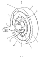
- the Fig. 2 shows a schematic perspective view of an embodiment of the knob 6 with an operating shaft 7 of the control device of the household appliance 1.
- the knob 6 has a guide portion 8, which extends from a rear side 9 of a base body 10 of the knob 6 out.
- a cover 11 is attached on the base body 10.
- the cover 11 may be latched to the base body 10.
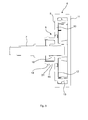
- on the base body 10 may be provided out of a front side 12 of the base body 10 outwardly projecting snap hook 13, which are adapted to intervene in a form-fitting manner in corresponding recesses of the cover 11.
- the guide section 8 has radial guide elements 14 and axial guide elements 15.
- radial guide elements 14 and axial guide elements 15 are provided.
- the guide members 14, 15 are preferably uniformly distributed around a receiving portion 16 for receiving an end portion of the operating shaft 7.
- the receiving portion 16 is arranged coaxially with the guide portion 8.
- Each radial guide element 14 has a curved sliding surface 17.
- Each axial guide element 15 has a latching hook 18.
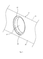
- the Fig. 4 shows a schematic perspective view of a section of an embodiment of the control panel 5.
- the control panel 5 has a in the Fig. 1 shown front 19 and a back 20.
- the control panel 5 has an opening 21, which is preferably circular.
- the radial guide elements 14 and in particular the sliding surfaces 17 of the radial guide elements 14 are adapted to slide on an outer wall 22 of the opening 21.
- the radial guide elements 14 are thus arranged for radially guiding the guide section 8 on the cylindrical outer wall 22 of the opening 21.
- the axial guide elements 15 are arranged for axially guiding the rotary knob 6 on the control panel 5.
- the radial guide elements 14 and / or the axial guide elements 15 are arranged in a circle around the receiving section 16.
- the radial guide elements 14 each have a corresponding to the opening 21 curvature.
- the latching hooks 18 of the axial guide elements 15th are adapted to lock the knob 6 on the control panel 5.
- a circular recess 23 surrounding the aperture 21 is provided, into which the latching hooks 18 can be snapped. End faces 24 ( Fig. 3 ) of the latching hooks 18 are adapted to slide on a bottom surface of the recess 23.
- the Fig. 5 shows in a schematic perspective view mounted on the control panel 5 rotary knob 6.
- the sliding surfaces 17 of the radial guide elements 14 are guided radially on the cylindrical outer wall 22 of the opening 21.
- the end faces 24 of the latching hooks 18 of the axial guide elements 15 slide on the recess 23, which is provided on the back 20 of the control panel 5.
- the axial guide elements 15 are guided axially on the control panel 5.
- the axial guide elements 15 are preferably resiliently deformable.
- the Fig. 6 shows in a schematic perspective view of the operating shaft 7 of the control device.
- the operating shaft 7 has a lateral flattening 25 on an end section facing the rotary knob 6.
- the lateral flattening 25 of the receiving portion 16 of the knob 6 engages positively.
- the operating shaft 7 is accommodated with play in the receiving portion 16.
- the knob 6 is formed integrally with material.
- the rotary knob 6 is a plastic injection molded component.
- a rib 26 is provided which is adapted to slide on the front side 19 of the control panel 5.
- the running rib 26 runs in an annular manner around the guide section 8 and the receiving section 16.
- the receiving portion 16, the guide portion 8 and the rib 26 are arranged coaxially.
- circularly arranged running knobs may be provided.
Landscapes
- Physics & Mathematics (AREA)
- General Physics & Mathematics (AREA)
- Engineering & Computer Science (AREA)
- Automation & Control Theory (AREA)
- Mechanical Control Devices (AREA)
- Switches With Compound Operations (AREA)
Description
- Die vorliegende Erfindung betrifft ein Haushaltsgerät.
- Eine Bedienblende eines Haushaltgeräts verdeckt üblicherweise eine oder mehrere Regeleinrichtungen zum Ansteuern des Haushaltgeräts. Auf oder an einer Vorderseite der Bedienblende können Bedienelemente wie beispielsweise Drehknöpfe zum Betätigen der Regeleinrichtungen vorgesehen sein.
- Die
WO 2009/077330 A1 beschreibt ein Haushaltgerät mit einem Drehknopf, der mit Hilfe von an der Bedienblende vorgesehenen Rasthaken mit der Bedienblende verbunden ist. - Vor diesem Hintergrund besteht eine Aufgabe der vorliegenden Erfindung darin, ein verbessertes Haushaltgerät zur Verfügung zu stellen.
- Demgemäß wird ein Haushaltgerät mit einer Bedienblende und einem Drehknopf zum Betätigen einer Regeleinrichtung des Haushaltgeräts vorgeschlagen, wobei die Bedienblende einen Durchbruch aufweist, in den ein Führungsabschnitt des Drehknopfs einführbar ist, wobei der Führungsabschnitt radiale Führungselemente zum radialen Führen des Führungsabschnitts an einer zylindrischen Außenwandung des Durchbruchs und axiale Führungselemente zum axialen Führen des Drehknopfs an der Bedienblende umfasst.
- Die Bedienblende kann auch als Bedienfront bezeichnet werden. Dadurch, dass an dem Drehknopf sowohl Führungselemente zur radialen Führung als auch Führungselemente zur axialen Führung des Drehknopfs an der Bedienblende vorgesehen sind, kann eine besonders spielfreie Lagerung des Drehknopfs mit geringen Spaltmaßen erzielt werden. Hierdurch entsteht eine sehr gute haptische Rückmeldung für einen Benutzer, der das Haushaltsgerät bedient. Weiterhin entsteht auch ein besonders hochwertiger Eindruck. Dadurch, dass der Drehknopf direkt an der Bedienblende geführt ist, kann darüber hinaus ein geringer Bauraum verwirklicht werden.
- Gemäß einer Ausführungsform weist jedes radiale Führungselement eine Gleitfläche auf, die dazu eingerichtet ist, auf der Außenwandung des Durchbruchs zu gleiten. Beispielsweise sind vier Führungselemente vorgesehen, die gleichmäßig um einen Umfang des Drehknopfs verteilt angeordnet sind.
- Gemäß einer weiteren Ausführungsform sind die radialen Führungselemente und/oder die axialen Führungselemente kreisförmig angeordnet.
- Vorzugsweise sind die radialen Führungselemente und die axialen Führungselemente auf einer gemeinsamen Kreisbahn positioniert.
- Gemäß einer weiteren Ausführungsform weisen die radialen Führungselemente jeweils eine zu dem Durchbruch korrespondierende Krümmung auf.
- Hierdurch wird ein vollflächiger Kontakt zwischen den radialen Führungselementen und der Außenwandung des Durchbruchs erzielt. Hierdurch ergibt sich eine besonders gute Führung des Drehknopfs.
- Gemäß einer weiteren Ausführungsform ist der Durchbruch kreisrund.
- Der Durchbruch ist beispielsweise eine in der Bedienblende vorgesehene Bohrung. Die Gleitflächen der radialen Führungselemente weisen vorzugsweise eine kreisbogenförmige Krümmung auf.
- Gemäß einer weiteren Ausführungsform weist jedes axiale Führungselement einen Rasthaken auf, der dazu eingerichtet ist, den Drehknopf an der Bedienblende zu verrasten.
- Hierdurch kann der Drehknopf ohne weitere Bauteile an der Bedienblende montiert werden. Die Rasthaken sind vorzugsweise federelastisch verformbar. Die Rasthaken können mittels eines Werkzeugs oder werkzeugfrei wieder gelöst werden, so dass eine Demontage des Drehknopfs einfach möglich ist.
- Gemäß einer weiteren Ausführungsform ist an der Bedienblende eine um den Durchbruch umlaufende ringförmige Ausnehmung vorgesehen, in die die Rasthaken einschnappbar sind.
- Hierzu kann ein besonders kompakter axialer Aufbau erreicht werden.
- Gemäß einer weiteren Ausführungsform ist die ringförmige Ausnehmung an einer Rückseite der Bedienblende vorgesehen.
- Stirnflächen der Rasthaken sind vorzugsweise dazu eingerichtet, auf einer Bodenfläche der Ausnehmung zu gleiten.
- Gemäß einer weiteren Ausführungsform sind die axialen Führungselemente federelastisch verformbar.
- Die axialen Führungselemente sind insbesondere aus einem federelastisch verformbaren Kunststoffmaterial gefertigt.
- Gemäß einer weiteren Ausführungsform weist der Drehknopf einen Aufnahmeabschnitt zum Aufnehmen eines Betätigungsschafts der Regeleinrichtung auf.
- Der Aufnahmeabschnitt ist insbesondere dazu eingerichtet, einen Endabschnitt des Betätigungsschafts spielbehaftet aufzunehmen. Hierdurch können Toleranzen, die bei der Befestigung der Regeleinrichtung auf einer Platine des Haushaltgeräts auftreten können, einfach ausgeglichen werden.
- Gemäß einer weiteren Ausführungsform ist der Aufnahmeabschnitt dazu eingerichtet, formschlüssig in den Betätigungsschaft einzugreifen.
- Der Betätigungsschaft weist vorzugsweise eine seitliche Abflachung auf, in die der Aufnahmeabschnitt formschlüssig eingreift. Der Aufnahmeabschnitt ist insbesondere korrespondierend zu der seitlichen Abflachung des Betätigungsschafts ausgebildet.
- Gemäß einer weiteren Ausführungsform ist der Aufnahmeabschnitt koaxial zu dem Führungsabschnitt angeordnet.
- Der Aufnahmeabschnitt ist insbesondere innerhalb des Führungsabschnitts positioniert.
- Gemäß einer weiteren Ausführungsform ist der Drehknopf materialeinstückig.
- Der Drehknopf ist vorzugsweise ein Kunststoffspritzgussbauteil. Hierdurch kann der Drehknopf kostengünstig in großen Stückzahlen hergestellt werden.
- Gemäß einer weiteren Ausführungsform weist der Drehknopf eine Laufrippe auf, die dazu eingerichtet ist, auf einer Vorderseite der Bedienblende zu gleiten.
- Hierdurch wird eine linienförmige Auflagefläche erzielt. Dadurch ergibt sich eine besonders gute haptische Rückmeldung. Alternativ können zu der Laufrippe auch kreisförmig angeordnete Laufnoppen vorgesehen sein.
- Gemäß einer weiteren Ausführungsform umläuft die Laufrippe ringförmig um den Führungsabschnitt.
- Insbesondere sind die Laufrippe, der Aufnahmeabschnitt und der Führungsabschnitt koaxial zueinander positioniert.
- Weitere mögliche Implementierungen des Haushaltgeräts umfassen auch nicht explizit genannte Kombinationen von zuvor oder im Folgenden bezüglich der Ausführungsbeispiele beschriebenen Merkmale oder Ausführungsformen. Dabei wird der Fachmann auch Einzelaspekte als Verbesserungen oder Ergänzungen zu der jeweiligen Grundform des Haushaltgeräts hinzufügen.
- Weitere vorteilhafte Ausgestaltungen und Aspekte des Haushaltsgeräts sind Gegenstand der Unteransprüche sowie der im Folgenden beschriebenen Ausführungsbeispiele des Haushaltsgeräts. Im Weiteren wird das Haushaltsgerät anhand von bevorzugten Ausführungsformen unter Bezugnahme auf die beigelegten Figuren näher erläutert.
-
Fig. 1 zeigt eine schematische perspektivische Ansicht einer Ausführungsform eines Haushaltsgeräts; -
Fig. 2 zeigt eine schematische perspektivische Ansicht einer Ausführungsform eines Drehknopfs für das Haushaltsgerät gemäß derFig. 1 ; -
Fig. 3 zeigt eine schematische Schnittansicht des Drehknopfs gemäß derFig. 2 ; -
Fig. 4 zeigt eine schematische perspektivische Teilansicht einer Bedienblende für das Haushaltgerät gemäß derFig. 1 ; -
Fig. 5 zeigt eine weitere schematische perspektivische Ansicht der Bedienblende gemäß derFig. 4 ; und -
Fig. 6 zeigt eine schematische perspektivische Ansicht eines Betätigungsschafts für den Drehknopf gemäß derFig. 2 . - In den Figuren sind gleiche oder funktionsgleiche Elemente mit denselben Bezugszeichen versehen worden, sofern nichts anderes angegeben ist.
- Die
Fig. 1 zeigt eine schematische perspektivische Ansicht eines Haushaltsgeräts 1. Das Haushaltsgerät 1 kann ein Haushaltsgargerät wie beispielsweise ein Backofen, ein Mikrowellengerät, ein Backofen mit Mikrowellenfunktion oder dergleichen sein. Weiterhin kann das Haushaltsgerät 1 ein Kühlgerät, eine Waschmaschine, ein Wäschetrockner, eine Geschirrspülmaschine oder dergleichen sein. Das Haushaltsgerät 1 weist einen quader- oder würfelförmigen Aufnahmebereich 2 auf, der durch eine Tür 3 verschließbar ist. Der Aufnahmebereich 2 kann ein Garraum oder eine Backofenmuffel eines Haushaltsgargeräts sein. Weiterhin kann der Aufnahmebereich 2 beispielsweise ein Spülbehälter einer Geschirrspülmaschine sein. - Der Aufnahmebereich 2 kann im Inneren eines Gehäuses des Haushaltsgeräts 1 angeordnet sein. Die Tür 3 ist in der
Fig. 1 in ihrer geschlossenen Stellung dargestellt. Durch Schwenken um eine an einem unteren Ende der Tür 3 vorgesehene Schwenkachse kann die Tür 3 geschlossen oder geöffnet werden. Alternativ kann die Tür 3 seitlich an dem Aufnahmebereich 2 angeschlagen sein. Weiterhin kann die Tür 3 an einem aus dem Aufnahmebereich 2 herausziehbaren Wagen, insbesondere einem Backwagen, angeordnet sein. An einem oberen Abschnitt der Tür 3 kann ein Griff 4 vorgesehen sein. Das Haushaltgerät 1 weist ferner eine Bedienblende 5 bzw. Bedienfront 5 auf. An der Bedienblende 5 kann zumindest ein Drehknopf 6 zum Betätigen einer Regeleinrichtung des Haushaltgeräts 1 vorgesehen sein. Vorzugsweise sind mehrere Drehknöpfe 6 vorgesehen. - Die
Fig. 2 zeigt in einer schematischen perspektivischen Ansicht eine Ausführungsform des Drehknopfs 6 mit einem Betätigungsschaft 7 der Regeleinrichtung des Haushaltgeräts 1. Der Drehknopf 6 weist einen Führungsabschnitt 8 auf, der sich aus einer Rückseite 9 eines Basiskörpers 10 des Drehknopfs 6 heraus erstreckt. An dem Basiskörper 10 ist eine Abdeckung 11 angebracht. Die Abdeckung 11 kann mit dem Basiskörper 10 verrastet sein. Hierzu können, wie in derFig. 3 gezeigt, an dem Basiskörper 10 sich aus einer Vorderseite 12 des Basiskörpers 10 herauserstreckende Schnapphaken 13 vorgesehen sein, die dazu eingerichtet sind, in entsprechende Ausnehmungen der Abdeckung 11 formschlüssig einzugreifen. - Der Führungsabschnitt 8 weist radiale Führungselemente 14 und axiale Führungselemente 15 auf. Beispielsweise sind vier radiale Führungselemente 14 und vier axiale Führungselemente 15 vorgesehen. Die Führungselemente 14, 15 sind vorzugsweise gleichmäßig um einen Aufnahmeabschnitt 16 zum Aufnehmen eines Endabschnitts des Betätigungsschafts 7 herum gleichmäßig verteilt angeordnet. Der Aufnahmeabschnitt 16 ist koaxial zu dem Führungsabschnitt 8 angeordnet. Jedes radiale Führungselement 14 weist eine gekrümmte Gleitfläche 17 auf. Jedes axiale Führungselement 15 weist einen Rasthaken 18 auf.
- Die
Fig. 4 zeigt in einer schematischen perspektivischen Ansicht einen Ausschnitt einer Ausführungsform der Bedienblende 5. Die Bedienblende 5 weist eine in derFig. 1 gezeigte Vorderseite 19 sowie eine Rückseite 20 auf. Die Bedienblende 5 weist einen Durchbruch 21 auf, der vorzugsweise kreisrund ist. In den Durchbruch 21 ist der Führungsabschnitt 8 des Drehknopfs 6 einführbar. Die radialen Führungselemente 14 und insbesondere die Gleitflächen 17 der radialen Führungselemente 14 sind dazu eingerichtet, auf einer Außenwandung 22 des Durchbruchs 21 zu gleiten. Die radialen Führungselemente 14 sind somit zum radialen Führen des Führungsabschnitts 8 an der zylindrischen Außenwandung 22 des Durchbruchs 21 eingerichtet. - Weiterhin sind die axialen Führungselemente 15 zum axialen Führen des Drehknopfs 6 an der Bedienblende 5 eingerichtet. Die radialen Führungselemente 14 und/oder die axialen Führungselemente 15 sind kreisförmig um den Aufnahmeabschnitt 16 herum angeordnet. Die radialen Führungselemente 14 weisen jeweils eine zu dem Durchbruch 21 korrespondierende Krümmung auf. Die Rasthaken 18 der axialen Führungselemente 15 sind dazu eingerichtet, den Drehknopf 6 an der Bedienblende 5 zu verrasten. Hierzu ist an der Rückseite 20 der Bedienblende 5 eine um den Durchbruch 21 umlaufende ringförmige Ausnehmung 23 vorgesehen, in die die Rasthaken 18 einschnappbar sind. Stirnflächen 24 (
Fig. 3 ) der Rasthaken 18 sind dazu eingerichtet, auf einer Bodenfläche der Ausnehmung 23 zu gleiten. - Die
Fig. 5 zeigt in einer schematischen perspektivischen Ansicht den an die Bedienblende 5 montierten Drehknopf 6. Die Gleitflächen 17 der radialen Führungselemente 14 sind radial an der zylindrischen Außenwandung 22 des Durchbruchs 21 geführt. Die Stirnflächen 24 der Rasthaken 18 der axialen Führungselemente 15 gleiten auf der Ausnehmung 23 ab, die an der Rückseite 20 der Bedienblende 5 vorgesehen ist. Hierdurch sind die axialen Führungselemente 15 axial an der Bedienblende 5 geführt. Die axialen Führungselemente 15 sind vorzugsweise federelastisch verformbar. - Die
Fig. 6 zeigt in einer schematischen perspektivischen Ansicht den Betätigungsschaft 7 der Regeleinrichtung. Der Betätigungsschaft 7 weist an einem dem Drehknopf 6 zugewandten Endabschnitt eine seitliche Abflachung 25 auf. In die seitliche Abflachung 25 greift der Aufnahmeabschnitt 16 des Drehknopfs 6 formschlüssig ein. Vorzugsweise ist der Betätigungsschaft 7 spielbehaftet in dem Aufnahmeabschnitt 16 aufgenommen. Hierdurch können Toleranzen, die bei der Montage der Regeleinrichtung entstehen können, ausgeglichen werden. - Vorzugsweise ist der Drehknopf 6 materialeinstückig ausgebildet. Insbesondere ist der Drehknopf 6 ein Kunststoffspritzgussbauteil. Wie die
Fig. 2 zeigt, ist an der Rückseite 9 des Drehknopfs eine Laufrippe 26 vorgesehen, die dazu eingerichtet ist, auf der Vorderseite 19 der Bedienblende 5 zu gleiten. Die Laufrippe 26 läuft ringförmig um den Führungsabschnitt 8 und den Aufnahmeabschnitt 16 um. Vorzugsweise sind der Aufnahmeabschnitt 16, der Führungsabschnitt 8 und die Laufrippe 26 koaxial angeordnet. Alternativ zu der Laufrippe 26 können kreisförmig angeordnete Laufnoppen vorgesehen sein. - Obwohl die vorliegende Erfindung anhand von Ausführungsbeispielen beschrieben wurde, ist sie vielfältig modifizierbar.
-
- 1
- Haushaltsgerät
- 2
- Aufnahmebereich
- 3
- Tür
- 4
- Griff
- 5
- Bedienblende
- 6
- Drehknopf
- 7
- Betätigungsschaft
- 8
- Führungsabschnitt
- 9
- Rückseite
- 10
- Basiskörper
- 11
- Abdeckung
- 12
- Vorderseite
- 13
- Schnapphaken
- 14
- Führungselement
- 15
- Führungselement
- 16
- Aufnahmeabschnitt
- 17
- Gleitfläche
- 18
- Rasthaken
- 19
- Vorderseite
- 20
- Rückseite
- 21
- Durchbruch
- 22
- Außenwandung
- 23
- Ausnehmung
- 24
- Stirnfläche
- 25
- Abflachung
- 26
- Laufrippe
Claims (15)
- Haushaltsgerät (1) mit einer Bedienblende (5) und einem Drehknopf (6) zum Betätigen einer Regeleinrichtung des Haushaltsgeräts (1), wobei die Bedienblende (5) einen Durchbruch (21) aufweist, in den ein Führungsabschnitt (8) des Drehknopfs (6) einführbar ist, wobei der Führungsabschnitt (8) radiale Führungselemente (14) zum radialen Führen des Führungsabschnitts (8) an einer zylindrischen Außenwandung (22) des Durchbruchs (21) und axiale Führungselemente (15) zum axialen Führen des Drehknopfs (6) an der Bedienblende (5) umfasst.
- Haushaltsgerät nach Anspruch 1, dadurch gekennzeichnet, dass jedes radiale Führungselement (14) eine Gleitfläche (17) aufweist, die dazu eingerichtet ist, auf der Außenwandung (22) des Durchbruchs (21) zu gleiten.
- Haushaltsgerät nach Anspruch 1 oder 2, dadurch gekennzeichnet, dass die radialen Führungselemente (14) und/oder die axialen Führungselemente (15) kreisförmig angeordnet sind.
- Haushaltsgerät nach einem der Ansprüche 1 - 3, dadurch gekennzeichnet, dass die radialen Führungselemente (14) jeweils eine zu dem Durchbruch (21) korrespondierende Krümmung aufweisen.
- Haushaltsgerät nach einem der Ansprüche 1 - 4, dadurch gekennzeichnet, dass der Durchbruch (21) kreisrund ist.
- Haushaltsgerät nach einem der Ansprüche 1 - 5, dadurch gekennzeichnet, dass jedes axiale Führungselement (15) einen Rasthaken (18) aufweist, der dazu eingerichtet ist, den Drehknopf (6) an der Bedienblende (5) zu verrasten.
- Haushaltsgerät nach Anspruch 6, dadurch gekennzeichnet, dass an der Bedienblende (5) eine um den Durchbruch (21) umlaufende ringförmige Ausnehmung (23) vorgesehen ist, in die die Rasthaken (18) einschnappbar sind.
- Haushaltsgerät nach Anspruch 7, dadurch gekennzeichnet, dass die ringförmige Ausnehmung (23) an einer Rückseite (20) der Bedienblende (5) vorgesehen ist.
- Haushaltsgerät nach einem der Ansprüche 1 - 8, dadurch gekennzeichnet, dass die axialen Führungselemente (15) federelastisch verformbar sind.
- Haushaltsgerät nach einem der Ansprüche 1 - 9, dadurch gekennzeichnet, dass der Drehknopf (6) einen Aufnahmeabschnitt (16) zum Aufnehmen eines Betätigungsschafts (7) der Regeleinrichtung aufweist.
- Haushaltsgerät nach Anspruch 10, dadurch gekennzeichnet, dass der Aufnahmeabschnitt (16) dazu eingerichtet ist, formschlüssig in den Betätigungsschaft (7) einzugreifen.
- Haushaltsgerät nach Anspruch 10 oder 11, dadurch gekennzeichnet, dass der Aufnahmeabschnitt (16) koaxial zu dem Führungsabschnitt (8) angeordnet ist.
- Haushaltsgerät nach einem der Ansprüche 1 - 12, dadurch gekennzeichnet, dass der Drehknopf (6) materialeinstückig ist.
- Haushaltsgerät nach einem der Ansprüche 1 - 13, dadurch gekennzeichnet, dass der Drehknopf (6) eine Laufrippe (26) aufweist, die dazu eingerichtet ist, auf einer Vorderseite (19) der Bedienblende (5) zu gleiten.
- Haushaltsgerät nach Anspruch 14, dadurch gekennzeichnet, dass die Laufrippe (26) ringförmig um den Führungsabschnitt (8) umläuft.
Applications Claiming Priority (1)
| Application Number | Priority Date | Filing Date | Title |
|---|---|---|---|
| DE102014214834.0A DE102014214834A1 (de) | 2014-07-29 | 2014-07-29 | Haushaltsgerät |
Publications (3)
| Publication Number | Publication Date |
|---|---|
| EP2980673A2 true EP2980673A2 (de) | 2016-02-03 |
| EP2980673A3 EP2980673A3 (de) | 2016-08-03 |
| EP2980673B1 EP2980673B1 (de) | 2019-05-29 |
Family
ID=53835259
Family Applications (1)
| Application Number | Title | Priority Date | Filing Date |
|---|---|---|---|
| EP15178176.2A Active EP2980673B1 (de) | 2014-07-29 | 2015-07-24 | Haushaltsgerät |
Country Status (2)
| Country | Link |
|---|---|
| EP (1) | EP2980673B1 (de) |
| DE (1) | DE102014214834A1 (de) |
Cited By (2)
| Publication number | Priority date | Publication date | Assignee | Title |
|---|---|---|---|---|
| WO2018054801A1 (en) * | 2016-09-20 | 2018-03-29 | Arcelik Anonim Sirketi | A household appliance comprising a knob |
| CN111534976A (zh) * | 2019-01-22 | 2020-08-14 | Bsh家用电器有限公司 | 具有切换元件的家用器具 |
Citations (1)
| Publication number | Priority date | Publication date | Assignee | Title |
|---|---|---|---|---|
| WO2009077330A1 (de) | 2007-12-18 | 2009-06-25 | BSH Bosch und Siemens Hausgeräte GmbH | Haushaltsgerät |
Family Cites Families (5)
| Publication number | Priority date | Publication date | Assignee | Title |
|---|---|---|---|---|
| DE3803356A1 (de) * | 1988-02-05 | 1989-08-17 | Bauknecht Hausgeraete | Drehknopf fuer steuergeraete o. dgl. |
| DD291859A5 (de) * | 1990-01-24 | 1991-07-11 | Elektrowaerme Soernewitz,De | Drehknopf mit ratsche |
| DE102005010619A1 (de) * | 2005-03-08 | 2006-09-14 | Siemens Ag Österreich | Berührungsloser Rotationsschalter für ein tragbares elektronisches Gerät |
| DE102007046276B3 (de) * | 2007-09-27 | 2009-01-15 | Siemens Ag | Drehbetätiger für eine Einstelleinrichtung sowie Einstelleinrichtung |
| CN201355459Y (zh) * | 2009-01-22 | 2009-12-02 | 深圳市福嘉太科技有限公司 | 用于薄型电子装置的旋转式电量调节器件 |
-
2014
- 2014-07-29 DE DE102014214834.0A patent/DE102014214834A1/de not_active Withdrawn
-
2015
- 2015-07-24 EP EP15178176.2A patent/EP2980673B1/de active Active
Patent Citations (1)
| Publication number | Priority date | Publication date | Assignee | Title |
|---|---|---|---|---|
| WO2009077330A1 (de) | 2007-12-18 | 2009-06-25 | BSH Bosch und Siemens Hausgeräte GmbH | Haushaltsgerät |
Cited By (3)
| Publication number | Priority date | Publication date | Assignee | Title |
|---|---|---|---|---|
| WO2018054801A1 (en) * | 2016-09-20 | 2018-03-29 | Arcelik Anonim Sirketi | A household appliance comprising a knob |
| CN111534976A (zh) * | 2019-01-22 | 2020-08-14 | Bsh家用电器有限公司 | 具有切换元件的家用器具 |
| CN111534976B (zh) * | 2019-01-22 | 2023-12-22 | Bsh家用电器有限公司 | 具有切换元件的家用器具 |
Also Published As
| Publication number | Publication date |
|---|---|
| EP2980673B1 (de) | 2019-05-29 |
| DE102014214834A1 (de) | 2016-02-04 |
| EP2980673A3 (de) | 2016-08-03 |
Similar Documents
| Publication | Publication Date | Title |
|---|---|---|
| DE102016101008A1 (de) | Kochgerät | |
| EP3183499B1 (de) | Bedienvorrichtung für ein haushaltsgerät mit einem bedienelement und einem im bedienelement ausgebildeten anzeigebereich | |
| DE8231565U1 (de) | Drehknopf eines in einem Haushaltgerätegehäuse vorgesehenen Schalt- oder Steuergerätes | |
| EP3333489B2 (de) | Haushaltsgargerät | |
| EP2980673B1 (de) | Haushaltsgerät | |
| DE102014221974A1 (de) | Haushaltsgerät, insbesondere Durchlauferhitzer | |
| DE102018121502A1 (de) | Gargerät, umfassend einen ersten und einen zweiten Garraum | |
| EP1596134A2 (de) | Herdschaltuhr | |
| EP2234001B1 (de) | Bedieneinrichtung für ein Hausgerät | |
| EP3469969B1 (de) | Elektromotorisch betriebene küchenmaschine sowie rührgefäss und rührwerk dafür | |
| EP0103135A2 (de) | Elektroherd | |
| EP3035147B1 (de) | Sicherbare vorrichtung zum betätigen eines elektronischen bauteils | |
| DE2744514A1 (de) | Drehknopfverriegelungsvorrichtung an mit heizgeraeten ausgestatteten haushaltsgeraeten | |
| EP3338027B1 (de) | Bedienvorrichtung für ein haushaltsgerät mit einem distanzelement sowie haushaltsgerät mit einer bedienvorrichtung | |
| DE102016218493A1 (de) | Thermostatanordnung und Haushaltsgargerät | |
| EP2980672B1 (de) | Versenkbares bedienelement für ein haushaltsgerät mit einer zweiteiligen bedienelementkopfaufnahme | |
| DE10106824A1 (de) | Gargeräterahmen | |
| EP3771388A1 (de) | Multifunktionskochgerät | |
| EP2357414B1 (de) | Hausgerät zum Zubereiten von Lebensmitteln mit einer Lagerbuchse | |
| EP2429361B1 (de) | Küchengerät mit werkzeugschublade | |
| EP3182017B1 (de) | Haushaltgerät | |
| DE102019116335A1 (de) | Gargerät mit einem durch eine Tür verschließbaren Garraum | |
| DE102005006352A1 (de) | Elektrischer Wasserkocher und Verfahren zur Montage eines kleinen Haushaltsgerätes | |
| DE102022123739A1 (de) | Haushaltsgerät mit einer Tür und einer Türaufwerfervorrichtung | |
| DE202022102402U1 (de) | Küchenmaschine sowie Erweiterungsgerät dafür |
Legal Events
| Date | Code | Title | Description |
|---|---|---|---|
| PUAI | Public reference made under article 153(3) epc to a published international application that has entered the european phase |
Free format text: ORIGINAL CODE: 0009012 |
|
| AK | Designated contracting states |
Kind code of ref document: A2 Designated state(s): AL AT BE BG CH CY CZ DE DK EE ES FI FR GB GR HR HU IE IS IT LI LT LU LV MC MK MT NL NO PL PT RO RS SE SI SK SM TR |
|
| AX | Request for extension of the european patent |
Extension state: BA ME |
|
| PUAL | Search report despatched |
Free format text: ORIGINAL CODE: 0009013 |
|
| AK | Designated contracting states |
Kind code of ref document: A3 Designated state(s): AL AT BE BG CH CY CZ DE DK EE ES FI FR GB GR HR HU IE IS IT LI LT LU LV MC MK MT NL NO PL PT RO RS SE SI SK SM TR |
|
| AX | Request for extension of the european patent |
Extension state: BA ME |
|
| RIC1 | Information provided on ipc code assigned before grant |
Ipc: G05G 1/08 20060101AFI20160624BHEP Ipc: G05G 1/12 20060101ALN20160624BHEP |
|
| STAA | Information on the status of an ep patent application or granted ep patent |
Free format text: STATUS: REQUEST FOR EXAMINATION WAS MADE |
|
| 17P | Request for examination filed |
Effective date: 20170203 |
|
| RBV | Designated contracting states (corrected) |
Designated state(s): AL AT BE BG CH CY CZ DE DK EE ES FI FR GB GR HR HU IE IS IT LI LT LU LV MC MK MT NL NO PL PT RO RS SE SI SK SM TR |
|
| STAA | Information on the status of an ep patent application or granted ep patent |
Free format text: STATUS: EXAMINATION IS IN PROGRESS |
|
| 17Q | First examination report despatched |
Effective date: 20180214 |
|
| RIC1 | Information provided on ipc code assigned before grant |
Ipc: G05G 1/12 20060101ALN20181031BHEP Ipc: G05G 1/08 20060101AFI20181031BHEP |
|
| GRAP | Despatch of communication of intention to grant a patent |
Free format text: ORIGINAL CODE: EPIDOSNIGR1 |
|
| STAA | Information on the status of an ep patent application or granted ep patent |
Free format text: STATUS: GRANT OF PATENT IS INTENDED |
|
| INTG | Intention to grant announced |
Effective date: 20190102 |
|
| GRAS | Grant fee paid |
Free format text: ORIGINAL CODE: EPIDOSNIGR3 |
|
| GRAA | (expected) grant |
Free format text: ORIGINAL CODE: 0009210 |
|
| STAA | Information on the status of an ep patent application or granted ep patent |
Free format text: STATUS: THE PATENT HAS BEEN GRANTED |
|
| AK | Designated contracting states |
Kind code of ref document: B1 Designated state(s): AL AT BE BG CH CY CZ DE DK EE ES FI FR GB GR HR HU IE IS IT LI LT LU LV MC MK MT NL NO PL PT RO RS SE SI SK SM TR |
|
| REG | Reference to a national code |
Ref country code: GB Ref legal event code: FG4D Free format text: NOT ENGLISH |
|
| REG | Reference to a national code |
Ref country code: CH Ref legal event code: EP |
|
| REG | Reference to a national code |
Ref country code: AT Ref legal event code: REF Ref document number: 1138662 Country of ref document: AT Kind code of ref document: T Effective date: 20190615 |
|
| REG | Reference to a national code |
Ref country code: DE Ref legal event code: R096 Ref document number: 502015009167 Country of ref document: DE |
|
| REG | Reference to a national code |
Ref country code: IE Ref legal event code: FG4D Free format text: LANGUAGE OF EP DOCUMENT: GERMAN |
|
| REG | Reference to a national code |
Ref country code: NL Ref legal event code: MP Effective date: 20190529 |
|
| REG | Reference to a national code |
Ref country code: LT Ref legal event code: MG4D |
|
| PG25 | Lapsed in a contracting state [announced via postgrant information from national office to epo] |
Ref country code: PT Free format text: LAPSE BECAUSE OF FAILURE TO SUBMIT A TRANSLATION OF THE DESCRIPTION OR TO PAY THE FEE WITHIN THE PRESCRIBED TIME-LIMIT Effective date: 20190930 Ref country code: SE Free format text: LAPSE BECAUSE OF FAILURE TO SUBMIT A TRANSLATION OF THE DESCRIPTION OR TO PAY THE FEE WITHIN THE PRESCRIBED TIME-LIMIT Effective date: 20190529 Ref country code: LT Free format text: LAPSE BECAUSE OF FAILURE TO SUBMIT A TRANSLATION OF THE DESCRIPTION OR TO PAY THE FEE WITHIN THE PRESCRIBED TIME-LIMIT Effective date: 20190529 Ref country code: ES Free format text: LAPSE BECAUSE OF FAILURE TO SUBMIT A TRANSLATION OF THE DESCRIPTION OR TO PAY THE FEE WITHIN THE PRESCRIBED TIME-LIMIT Effective date: 20190529 Ref country code: FI Free format text: LAPSE BECAUSE OF FAILURE TO SUBMIT A TRANSLATION OF THE DESCRIPTION OR TO PAY THE FEE WITHIN THE PRESCRIBED TIME-LIMIT Effective date: 20190529 Ref country code: AL Free format text: LAPSE BECAUSE OF FAILURE TO SUBMIT A TRANSLATION OF THE DESCRIPTION OR TO PAY THE FEE WITHIN THE PRESCRIBED TIME-LIMIT Effective date: 20190529 Ref country code: NO Free format text: LAPSE BECAUSE OF FAILURE TO SUBMIT A TRANSLATION OF THE DESCRIPTION OR TO PAY THE FEE WITHIN THE PRESCRIBED TIME-LIMIT Effective date: 20190829 Ref country code: HR Free format text: LAPSE BECAUSE OF FAILURE TO SUBMIT A TRANSLATION OF THE DESCRIPTION OR TO PAY THE FEE WITHIN THE PRESCRIBED TIME-LIMIT Effective date: 20190529 |
|
| PG25 | Lapsed in a contracting state [announced via postgrant information from national office to epo] |
Ref country code: GR Free format text: LAPSE BECAUSE OF FAILURE TO SUBMIT A TRANSLATION OF THE DESCRIPTION OR TO PAY THE FEE WITHIN THE PRESCRIBED TIME-LIMIT Effective date: 20190830 Ref country code: LV Free format text: LAPSE BECAUSE OF FAILURE TO SUBMIT A TRANSLATION OF THE DESCRIPTION OR TO PAY THE FEE WITHIN THE PRESCRIBED TIME-LIMIT Effective date: 20190529 Ref country code: BG Free format text: LAPSE BECAUSE OF FAILURE TO SUBMIT A TRANSLATION OF THE DESCRIPTION OR TO PAY THE FEE WITHIN THE PRESCRIBED TIME-LIMIT Effective date: 20190829 Ref country code: RS Free format text: LAPSE BECAUSE OF FAILURE TO SUBMIT A TRANSLATION OF THE DESCRIPTION OR TO PAY THE FEE WITHIN THE PRESCRIBED TIME-LIMIT Effective date: 20190529 |
|
| PG25 | Lapsed in a contracting state [announced via postgrant information from national office to epo] |
Ref country code: NL Free format text: LAPSE BECAUSE OF FAILURE TO SUBMIT A TRANSLATION OF THE DESCRIPTION OR TO PAY THE FEE WITHIN THE PRESCRIBED TIME-LIMIT Effective date: 20190529 Ref country code: DK Free format text: LAPSE BECAUSE OF FAILURE TO SUBMIT A TRANSLATION OF THE DESCRIPTION OR TO PAY THE FEE WITHIN THE PRESCRIBED TIME-LIMIT Effective date: 20190529 Ref country code: EE Free format text: LAPSE BECAUSE OF FAILURE TO SUBMIT A TRANSLATION OF THE DESCRIPTION OR TO PAY THE FEE WITHIN THE PRESCRIBED TIME-LIMIT Effective date: 20190529 Ref country code: CZ Free format text: LAPSE BECAUSE OF FAILURE TO SUBMIT A TRANSLATION OF THE DESCRIPTION OR TO PAY THE FEE WITHIN THE PRESCRIBED TIME-LIMIT Effective date: 20190529 Ref country code: RO Free format text: LAPSE BECAUSE OF FAILURE TO SUBMIT A TRANSLATION OF THE DESCRIPTION OR TO PAY THE FEE WITHIN THE PRESCRIBED TIME-LIMIT Effective date: 20190529 Ref country code: SK Free format text: LAPSE BECAUSE OF FAILURE TO SUBMIT A TRANSLATION OF THE DESCRIPTION OR TO PAY THE FEE WITHIN THE PRESCRIBED TIME-LIMIT Effective date: 20190529 |
|
| PG25 | Lapsed in a contracting state [announced via postgrant information from national office to epo] |
Ref country code: SM Free format text: LAPSE BECAUSE OF FAILURE TO SUBMIT A TRANSLATION OF THE DESCRIPTION OR TO PAY THE FEE WITHIN THE PRESCRIBED TIME-LIMIT Effective date: 20190529 Ref country code: IT Free format text: LAPSE BECAUSE OF FAILURE TO SUBMIT A TRANSLATION OF THE DESCRIPTION OR TO PAY THE FEE WITHIN THE PRESCRIBED TIME-LIMIT Effective date: 20190529 Ref country code: MC Free format text: LAPSE BECAUSE OF FAILURE TO SUBMIT A TRANSLATION OF THE DESCRIPTION OR TO PAY THE FEE WITHIN THE PRESCRIBED TIME-LIMIT Effective date: 20190529 |
|
| REG | Reference to a national code |
Ref country code: CH Ref legal event code: PL |
|
| REG | Reference to a national code |
Ref country code: DE Ref legal event code: R097 Ref document number: 502015009167 Country of ref document: DE |
|
| PG25 | Lapsed in a contracting state [announced via postgrant information from national office to epo] |
Ref country code: TR Free format text: LAPSE BECAUSE OF FAILURE TO SUBMIT A TRANSLATION OF THE DESCRIPTION OR TO PAY THE FEE WITHIN THE PRESCRIBED TIME-LIMIT Effective date: 20190529 |
|
| PLBE | No opposition filed within time limit |
Free format text: ORIGINAL CODE: 0009261 |
|
| STAA | Information on the status of an ep patent application or granted ep patent |
Free format text: STATUS: NO OPPOSITION FILED WITHIN TIME LIMIT |
|
| REG | Reference to a national code |
Ref country code: BE Ref legal event code: MM Effective date: 20190731 |
|
| GBPC | Gb: european patent ceased through non-payment of renewal fee |
Effective date: 20190829 |
|
| PG25 | Lapsed in a contracting state [announced via postgrant information from national office to epo] |
Ref country code: PL Free format text: LAPSE BECAUSE OF FAILURE TO SUBMIT A TRANSLATION OF THE DESCRIPTION OR TO PAY THE FEE WITHIN THE PRESCRIBED TIME-LIMIT Effective date: 20190529 |
|
| 26N | No opposition filed |
Effective date: 20200303 |
|
| PG25 | Lapsed in a contracting state [announced via postgrant information from national office to epo] |
Ref country code: BE Free format text: LAPSE BECAUSE OF NON-PAYMENT OF DUE FEES Effective date: 20190731 Ref country code: SI Free format text: LAPSE BECAUSE OF FAILURE TO SUBMIT A TRANSLATION OF THE DESCRIPTION OR TO PAY THE FEE WITHIN THE PRESCRIBED TIME-LIMIT Effective date: 20190529 Ref country code: LI Free format text: LAPSE BECAUSE OF NON-PAYMENT OF DUE FEES Effective date: 20190731 Ref country code: LU Free format text: LAPSE BECAUSE OF NON-PAYMENT OF DUE FEES Effective date: 20190724 Ref country code: CH Free format text: LAPSE BECAUSE OF NON-PAYMENT OF DUE FEES Effective date: 20190731 |
|
| PG25 | Lapsed in a contracting state [announced via postgrant information from national office to epo] |
Ref country code: FR Free format text: LAPSE BECAUSE OF NON-PAYMENT OF DUE FEES Effective date: 20190729 |
|
| PG25 | Lapsed in a contracting state [announced via postgrant information from national office to epo] |
Ref country code: IE Free format text: LAPSE BECAUSE OF NON-PAYMENT OF DUE FEES Effective date: 20190724 |
|
| PG25 | Lapsed in a contracting state [announced via postgrant information from national office to epo] |
Ref country code: GB Free format text: LAPSE BECAUSE OF NON-PAYMENT OF DUE FEES Effective date: 20190829 |
|
| PG25 | Lapsed in a contracting state [announced via postgrant information from national office to epo] |
Ref country code: CY Free format text: LAPSE BECAUSE OF FAILURE TO SUBMIT A TRANSLATION OF THE DESCRIPTION OR TO PAY THE FEE WITHIN THE PRESCRIBED TIME-LIMIT Effective date: 20190529 |
|
| PG25 | Lapsed in a contracting state [announced via postgrant information from national office to epo] |
Ref country code: IS Free format text: LAPSE BECAUSE OF FAILURE TO SUBMIT A TRANSLATION OF THE DESCRIPTION OR TO PAY THE FEE WITHIN THE PRESCRIBED TIME-LIMIT Effective date: 20190929 |
|
| PG25 | Lapsed in a contracting state [announced via postgrant information from national office to epo] |
Ref country code: MT Free format text: LAPSE BECAUSE OF FAILURE TO SUBMIT A TRANSLATION OF THE DESCRIPTION OR TO PAY THE FEE WITHIN THE PRESCRIBED TIME-LIMIT Effective date: 20190529 Ref country code: HU Free format text: LAPSE BECAUSE OF FAILURE TO SUBMIT A TRANSLATION OF THE DESCRIPTION OR TO PAY THE FEE WITHIN THE PRESCRIBED TIME-LIMIT; INVALID AB INITIO Effective date: 20150724 |
|
| REG | Reference to a national code |
Ref country code: AT Ref legal event code: MM01 Ref document number: 1138662 Country of ref document: AT Kind code of ref document: T Effective date: 20200724 |
|
| PG25 | Lapsed in a contracting state [announced via postgrant information from national office to epo] |
Ref country code: AT Free format text: LAPSE BECAUSE OF NON-PAYMENT OF DUE FEES Effective date: 20200724 |
|
| PG25 | Lapsed in a contracting state [announced via postgrant information from national office to epo] |
Ref country code: MK Free format text: LAPSE BECAUSE OF FAILURE TO SUBMIT A TRANSLATION OF THE DESCRIPTION OR TO PAY THE FEE WITHIN THE PRESCRIBED TIME-LIMIT Effective date: 20190529 |
|
| PGFP | Annual fee paid to national office [announced via postgrant information from national office to epo] |
Ref country code: DE Payment date: 20250731 Year of fee payment: 11 |