EP2980525B1 - Interferometre à triple passage - Google Patents
Interferometre à triple passage Download PDFInfo
- Publication number
- EP2980525B1 EP2980525B1 EP15176437.0A EP15176437A EP2980525B1 EP 2980525 B1 EP2980525 B1 EP 2980525B1 EP 15176437 A EP15176437 A EP 15176437A EP 2980525 B1 EP2980525 B1 EP 2980525B1
- Authority
- EP
- European Patent Office
- Prior art keywords
- plane
- reflector
- imaging optical
- measurement
- plane plate
- Prior art date
- Legal status (The legal status is an assumption and is not a legal conclusion. Google has not performed a legal analysis and makes no representation as to the accuracy of the status listed.)
- Active
Links
- 238000003384 imaging method Methods 0.000 claims description 90
- 230000003287 optical effect Effects 0.000 claims description 64
- 238000005259 measurement Methods 0.000 claims description 50
- 238000001514 detection method Methods 0.000 claims description 16
- 125000006850 spacer group Chemical group 0.000 claims description 7
- 230000002452 interceptive effect Effects 0.000 claims description 6
- 230000007423 decrease Effects 0.000 claims 2
- 230000010287 polarization Effects 0.000 description 12
- 230000005855 radiation Effects 0.000 description 9
- 230000005540 biological transmission Effects 0.000 description 5
- 239000011521 glass Substances 0.000 description 5
- 238000001459 lithography Methods 0.000 description 3
- 230000001902 propagating effect Effects 0.000 description 3
- 238000010008 shearing Methods 0.000 description 3
- 239000006094 Zerodur Substances 0.000 description 1
- 230000002411 adverse Effects 0.000 description 1
- 239000006117 anti-reflective coating Substances 0.000 description 1
- 238000004140 cleaning Methods 0.000 description 1
- 238000000576 coating method Methods 0.000 description 1
- 230000001419 dependent effect Effects 0.000 description 1
- 238000006073 displacement reaction Methods 0.000 description 1
- 238000004519 manufacturing process Methods 0.000 description 1
- 239000000463 material Substances 0.000 description 1
- 238000000034 method Methods 0.000 description 1
- 238000005498 polishing Methods 0.000 description 1
- 230000000644 propagated effect Effects 0.000 description 1
- 230000006798 recombination Effects 0.000 description 1
- 238000005215 recombination Methods 0.000 description 1
- 239000004065 semiconductor Substances 0.000 description 1
- 238000000926 separation method Methods 0.000 description 1
- 239000000758 substrate Substances 0.000 description 1
Images


Classifications
-
- G—PHYSICS
- G01—MEASURING; TESTING
- G01B—MEASURING LENGTH, THICKNESS OR SIMILAR LINEAR DIMENSIONS; MEASURING ANGLES; MEASURING AREAS; MEASURING IRREGULARITIES OF SURFACES OR CONTOURS
- G01B9/00—Measuring instruments characterised by the use of optical techniques
- G01B9/02—Interferometers
- G01B9/02015—Interferometers characterised by the beam path configuration
-
- G—PHYSICS
- G01—MEASURING; TESTING
- G01B—MEASURING LENGTH, THICKNESS OR SIMILAR LINEAR DIMENSIONS; MEASURING ANGLES; MEASURING AREAS; MEASURING IRREGULARITIES OF SURFACES OR CONTOURS
- G01B11/00—Measuring arrangements characterised by the use of optical techniques
- G01B11/14—Measuring arrangements characterised by the use of optical techniques for measuring distance or clearance between spaced objects or spaced apertures
-
- G—PHYSICS
- G01—MEASURING; TESTING
- G01B—MEASURING LENGTH, THICKNESS OR SIMILAR LINEAR DIMENSIONS; MEASURING ANGLES; MEASURING AREAS; MEASURING IRREGULARITIES OF SURFACES OR CONTOURS
- G01B9/00—Measuring instruments characterised by the use of optical techniques
- G01B9/02—Interferometers
- G01B9/02015—Interferometers characterised by the beam path configuration
- G01B9/02017—Interferometers characterised by the beam path configuration with multiple interactions between the target object and light beams, e.g. beam reflections occurring from different locations
- G01B9/02018—Multipass interferometers, e.g. double-pass
-
- G—PHYSICS
- G01—MEASURING; TESTING
- G01B—MEASURING LENGTH, THICKNESS OR SIMILAR LINEAR DIMENSIONS; MEASURING ANGLES; MEASURING AREAS; MEASURING IRREGULARITIES OF SURFACES OR CONTOURS
- G01B9/00—Measuring instruments characterised by the use of optical techniques
- G01B9/02—Interferometers
- G01B9/02055—Reduction or prevention of errors; Testing; Calibration
- G01B9/02056—Passive reduction of errors
- G01B9/02057—Passive reduction of errors by using common path configuration, i.e. reference and object path almost entirely overlapping
-
- G—PHYSICS
- G01—MEASURING; TESTING
- G01B—MEASURING LENGTH, THICKNESS OR SIMILAR LINEAR DIMENSIONS; MEASURING ANGLES; MEASURING AREAS; MEASURING IRREGULARITIES OF SURFACES OR CONTOURS
- G01B9/00—Measuring instruments characterised by the use of optical techniques
- G01B9/02—Interferometers
- G01B9/02055—Reduction or prevention of errors; Testing; Calibration
- G01B9/02056—Passive reduction of errors
- G01B9/02061—Reduction or prevention of effects of tilts or misalignment
-
- G—PHYSICS
- G01—MEASURING; TESTING
- G01B—MEASURING LENGTH, THICKNESS OR SIMILAR LINEAR DIMENSIONS; MEASURING ANGLES; MEASURING AREAS; MEASURING IRREGULARITIES OF SURFACES OR CONTOURS
- G01B2290/00—Aspects of interferometers not specifically covered by any group under G01B9/02
- G01B2290/70—Using polarization in the interferometer
Definitions
- the present invention relates to an interferometer, which is particularly suitable for high-precision length and / or distance measurement.
- a so-called plane mirror interferometer is from the US 4,752,133 known. This comprises a light source, a first beam splitter and a detection unit. A radiation beam emitted by the light source is split into at least one measuring beam and at least one reference beam via the first beam splitter. The measuring beam and the reference beam propagate then each in a measuring arm and in a reference arm until reunification at the beam splitter.
- the measuring arm designed as a plane mirror measuring reflector is arranged on a movable measurement object; the reference arm has at least one reference reflector.
- the detection unit is at least one distance signal from the reunited, interfering measuring and reference beams with respect to the position of the test object detected.
- a polarization beam splitter cube As a beam splitter is in the US 4,752,133 a polarization beam splitter cube provided, as a reference reflector is a plane mirror, which is arranged between the measuring beams.
- the common triple prism of reference and measuring arm is glued or blasted on the beam splitter cube; Furthermore, the triple prism can also be arranged spatially separated from the beam splitter cube.
- both the polarization beam splitter cube and the triple prism are very expensive to produce.
- the different sides must be aligned highly precisely with one another, in particular if one or more triple prisms and possibly further optical components are arranged directly adjacent thereto.
- the spatially separated arrangement of beam splitter cube and triple prisms a likewise very complicated, drift-poor mounting of these components is required.
- the triple prism must have a relatively large design.
- the present invention has for its object to provide a compact constructed interferometer, which has as simple as possible to be manufactured optical components. This object is achieved by an interferometer with the features of claim 1.
- the imaging optics may each comprise two arranged on one side of a plane plate reflective grating lenses and arranged on the opposite side of the plane plate reflector, wherein the reflective sides of the grating lenses and the reflector facing each other.
- the first, fourth, fifth and eighth grating lenses each have a first focal length and the second, third, sixth and seventh grating lenses each a second focal length, which is twice as large as the first focal length.
- the imaging optics each comprise two arranged on a plane plate reflective grating lenses and arranged on the opposite plane plate reflector, wherein the reflective sides of the grating lenses and the reflector are facing each other.
- the first, fourth, fifth and eighth grating lenses each have a first focal length and the second, third, sixth and seventh grating lenses each have a second focal length which is twice as large as the first focal length.
- the first beam splitter prefferably be formed on the second plane plate as a grating or as a polarization-optical beam splitter layer, which are each arranged on one side of the second plane plate, which is oriented in the direction of the first plane plate.
- the measurement reflector and the reference reflector are each formed as a plane mirror reflector.
- a delay line is formed such that the measuring beam and the reference beam between splitting and reunification pass through identical optical paths in air and in the plane plates.
- spacers are arranged between the plane plates, which have recesses in the region of the propagating between the plane plates measurement and reference beams.
- the interferometer even in the case of a tilting or an offset of the measuring reflector and / or of the reference reflector from its respective nominal position, it is guaranteed that a resulting shearing of the measuring and / or reference beam bundle is effectively compensated intrinsically. It also results in these cases, no drop in the degree of modulation in the generated signals.
- the parallel guidance of the measuring beam and of the reference beam in the direction of the respectively associated measuring reflector or reference reflector makes it possible for them to be geometrically separated from one another and therefore the relative position of objects at different heights can be measured.
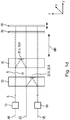
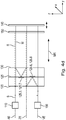
- FIGS. 1a-1d show the beam path in different views
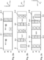
- FIGS. 2a-2c and FIGS. 3a-3c respectively show plan views of different sides of the plane plates used with the optical elements arranged thereon.
- the interferometer comprises at least one light source 10, a first beam splitter 30.1, a measuring reflector 40, a reference reflector 50, a detection unit 60 and at least two transparent plane plates 20, 30.
- the in the Figures 1a - 1c each lower plane plate 20 is hereinafter referred to as the first plane plate 20, the upper plane plate 30 as a second plane plate.
- the two flat plates 20, 30, which are made of a suitable glass material, for example, are arranged parallel to each other at a certain distance in the beam path between the light source 10 and the detection unit 60.
- the two plane plates 20, 30 are arranged in the present embodiment further non-parallel to the measuring reflector 40 and at an angle not equal to 90 ° with respect to the direction of incidence of the emitted from the light source beam S.
- the two plane plates 20, 30 have a length of approximately 10 to 15 cm in the indicated x-direction, a width of approximately 1 to 3 cm along the y-direction and a thickness of approximately 3. 5 cm along the z-direction.
- the distance between the two flat plates 20, 30 is about 1 - 2 cm.
- a measuring arm measuring reflector 40 formed as a plane mirror reflector
- a measuring object 41 which is arranged along a measuring direction MR movable relative to the remaining interferometer components.
- the measuring direction MR corresponds in the present example, the beam propagation direction between the plane plates 20, 30 and the measuring reflector 40 and extends into the Figures 1a - 1c accordingly, from bottom left to top right.
- the measuring object 41 may be e.g. to be a machine part such as a table of a lithography device, which is arranged to be movable along the measuring direction MR.
- a distance signal is determined with respect to a displacement of the measuring object 41 along the measuring direction MR.
- This distance signal can be used by a - not shown - control unit, for example, for positioning of the machine part.
- the reference reflector 50 is arranged, which is likewise designed as a plane mirror reflector and connected to an object 51.
- the object 51 is usually arranged stationary along the measuring direction MR in relation to the movable measuring object 50 in the corresponding machine.
- the measuring reflector 40 and the reference reflector 50 it is merely important that a relative mobility between the corresponding objects 41, 51 or the measuring reflector 40 and the reference reflector 50 along the measuring direction MR must be given.
- the measuring reflector 40 it would also be possible, for example, for the measuring reflector 40 to be stationary and the reference reflector 50 to be movable.
- the measuring arm and the reference arm can be seen extending the measuring arm and the reference arm from the second plane plate 30 in the interferometer according to the invention parallel to each other along the Measuring direction MR.
- the measuring beam M and the reference beam R thus propagate parallel to each other in the direction of the measuring reflector 40 and the reference reflector 50. This is ensured by the optical effects of a series of optical elements in the plane plates 20, 30, as will be explained in detail below.
- this orientation of the measuring and reference arm it is possible to detect changes in distance between different, relatively movable machine parts with high precision.
- a light source 10 such as a suitable laser, emits a beam S of linear polarization.
- the beam S propagates in a first plane, which is referred to below as a splitting plane AE and with the plane of FIG. 1a coincides.
- the beam S passes through the first transparent plane plate 20 and propagates further in the direction of the second plane plate 30.
- FIGS. 3a-3c which respectively show plan views of the first side 20_A and the second side 20_B of the first plane plate 20, are the regions in which the radiation beam S enters the first plane plate 20 or emerges from it again with AR; There is preferably applied an antireflective coating.
- the beam S then hits the first beam splitter 30.1.
- This is presently designed as a polarization-optical beam splitter layer which is arranged on that side of the second plane plate 30, which is oriented in the direction of the first plane plate 20; Subsequently, this page is referred to as the first side 30_A of the second plane plate 30.
- the first beam splitter 30.1 is also possible to form the first beam splitter 30.1 as a grating having a grating period which is smaller than the wavelength of the light source 10 used.
- the first Beam splitter 30.1 splits the radiation beam S incident thereon into at least one measuring beam M and at least one reference beam R.
- the split beams M, R have due to the provided polarization angle of the beam S of approximately 45 ° with respect to the first beam splitter 30.1 the same intensity in the interference. Both beams M, R each have a linear polarization, wherein the polarization directions in the measuring and reference beam M, R are oriented orthogonal to each other.
- the already mentioned splitting plane AE is spanned, which is identical to the plane in FIG. 1a is. In the FIGS. 1a-1d is from the resulting splitting at the first beam splitter 30.1, the measuring beam M shown in solid line, the reference beam R, however, dashed lines.
- the linearly polarized beam transmitted by the first beam splitter 30.1 forms the measuring beam M.
- the beam bundle reflected by the beam splitter 23 and orthogonally linearly polarized acts as reference beam R.
- the linearly polarized measuring beam M transmitted at the first beam splitter 30 first passes through the second plane plate 30 and, after leaving the plane plate 30 via the second side 30_B, propagates for the first time in the direction of the measuring reflector 40.
- a ⁇ / 4 plate 70 is arranged in the beam path of the measuring beam M.
- the measuring beam M After the back reflection on the measuring reflector 40 and the second passage through the ⁇ / 4 plate 70, the measuring beam M has a rotated by 90 ° Polarization and is now reflected by the first beam splitter 30.1 in the direction of the second side 30_B of the second plane plate 30.
- the measuring beam M in the second plane plate 30 passes through a first imaging optical system, which is characterized by a first reflective grating lens 30.2 on the second side 30_B, a first reflector 30.3 on the first side 30_A and a second reflective grating lens 30.7 on the second side 30_B of the plane plate 30 is formed.
- the first grating lens 30.2 in the splitting plane AE has in this case a first focal length f
- the second grating lens 30.7 in the intermediate plane ZE (FIG. FIG. 1b ) has a second focal length 2f, which in the present embodiment is twice as large as the first focal length f.
- d (f + 2f) / 2.
- the first imaging optics in the second plane plate 30 thus causes an offset of the measuring beam M from the splitting plane AE via the reflector 30.3 in the intermediate plane ZE. Furthermore, this causes an increase in the input beam diameter of the measuring beam M incident thereon; in the concrete example, the selected focal lengths f, 2f of the grating lenses 30.2, 30.7 result in a doubling of the input beam diameter of the measuring beam M.
- the measuring beam M from the first beam splitter 30.1 now transmits and propagates further in the direction of the first plane plate 20.
- On the second side 20_B of the measuring beam M strikes a reflector 20.2, from which it is reflected in the direction of the second plane plate 30.
- the measuring beam M then impinges on a further reflector 30.8, via which a renewed reflection takes place in the direction of a transmissive deflection grating 20.3 on the second side 20_B of the first plane plate 20. From the deflecting grid 20.3, the measuring beam M is then reflected twice over two further reflectors 20.4, 20.2 (reflection now on the rear side) and propagated in the direction of a second imaging optics in the first plane plate 20.
- the second imaging optics for the measuring beam M comprises a third grating lens 20.5 arranged in the intermediate plane ZE with the focal length 2f, a second reflector 20.6 and a fourth grating lens 20.9 with the focal length f arranged in the merging plane VE.
- the third and fourth grating lenses 20.5, 20.9 are formed like the first and second grating lens 30.2, 30.7 of the first imaging optics as reflection grating lenses.
- the second imaging optics thus result in an offset of the measurement beam M from the intermediate plane ZE to the merging plane VE.
- a halving of the beam diameter of the measuring beam M is effected on the basis of the selected focal lengths 2f, f of the two grating lenses 20.5, 20.9, so that this again has the original input beam diameter after passing through the fourth grating lens 20.9.
- the fundamental beam path of the measuring beam M in the measuring arm of the first embodiment of the interferometer according to the invention can thus be summarized as follows:
- the measuring beam M generated via the first beam splitter 30.1 strikes the measuring reflector 40 for the first time and becomes in the two plane plates 20, 30 after the first return reflection offset from the splitting plane AE in the intermediate plane ZE via the first imaging optics in the second plane plate 30; At the same time this results in a doubling of the beam diameter.
- the measuring beam M then passes perpendicular incident a second time on the measuring reflector 40 and is again reflected back to the two plane plates 20, 30.
- the second imaging optics in the first plane plate 20 then results in an offset of the measurement beam M into the merging plane VE.
- the doubled beam diameter is reduced or halved back to the original input beam diameter.
- the measuring beam M then strikes the measuring reflector 40 for a third time, is reflected by it and propagates via the beam splitter 30.1 in the direction of the detection unit 60.
- the beam path guide is ensured in the interferometer according to the invention that even in the case of a possible tilting of the measuring reflector 40 from its nominal position no beam shearing, ie neither angle nor local shear, in the measuring beam M result. Such beam shears would cause an intensity dip and loss of modulation in the generated distance signals. Any tilting of the measuring reflector 40 are rather automatically compensated via the intended beam path of the measuring beam M, since it is ensured that the measuring beam M always incident on the measuring reflector 40 perpendicular to the second impact. Thus, the measuring beam M would deflect at the first impact on the tilted by an angle ⁇ measuring reflector 40 by the angle 2 ⁇ .
- the exit angle from the first imaging optics halved, ie the measuring beam M leaves the first imaging optics at the exit angle ⁇ . This ensures that the measuring beam M always incident perpendicular to the measuring reflector M at the second impact and can propagate after the successful reflection quasi on the incident path in itself.
- the reference beam R generated on the first beam splitter 30.1 is displayed in the splitting plane AE as shown in FIG. 1a reflected in the direction of the first plane plate 20. From this results a return reflection of the reference beam R in the direction of the second plane plate 30, where the reference beam R strikes another, second beam splitter 30.4 on the first side 30_A arranged the second plane plate 30 and is also formed as a polarization optical beam splitter layer. From the second beam splitter 30.4, the further beam path of the reference beam R in the reference arm is basically identical to the beam path of the measuring beam M in the measuring arm from the first beam splitter 30.1.
- the reference beam R transmitted by the second beam splitter 30.4 propagates a first time along the measuring direction and parallel to the measuring beam in the direction of the reference reflector 50. From this it is reflected back and due to the passing of the ⁇ / 4 plate 80 twice from the second beam splitter 30.4 on the second Plane plate 30 reflected toward a third imaging optics. Similar to the first imaging optics in the measuring arm, this includes a fifth grating lens 30.5 in the splitting plane AE, a third reflector 30.6 and a sixth grating lens 30.9 in the intermediate plane ZE (FIG. FIG. 1b ). The fifth grating lens 30.5 has the focal length f, the sixth grating lens 30.9 has twice the focal length 2f. This imaging optics also results in an offset from the splitting plane AE into the intermediate plane ZE for the reference beam R, and also doubles the input beam diameter of the reference beam R.
- the reference beam R After reflection at the second grating lens 30.9, the reference beam R strikes, as in the beam path representation of the intermediate plane ZE in FIG. 1b shown again on the second beam splitter 30.4 and is reflected over it in the direction of the reference reflector 50, on which it then incident perpendicular to the second impact. After the back reflection and twice again through the ⁇ / 4 plate 80, the reference beam R is then transmitted by the second beam splitter 30.4 in the direction of the first plane plate 20. In the first plane plate 20, the reference beam R then impinges on a fourth imaging optics, comprising a seventh grating lens 20.7 in the intermediate plane ZE, a fourth reflector 20.8 and an eighth grating lens 20.11 in the merging plane (FIG. Figure 1c ).
- a fourth imaging optics comprising a seventh grating lens 20.7 in the intermediate plane ZE, a fourth reflector 20.8 and an eighth grating lens 20.11 in the merging plane (FIG. Figure 1c ).
- the seventh grating lens 20.7 has the focal length 2f, the eighth grating lens 20.11 the contrast halved focal length f.
- an offset of the reference beam R from the intermediate plane ZE to the merging plane VE results, while at the same time the beam diameter of the reference beam R is again reduced or halved.
- the reference beam R is thus analogous to the measurement beam M on the explained beam path and in particular on the optical effect of the third imaging optics ensures that the reference beam R incident at the second impact perpendicular to the reference reflector 50 and propagates back in itself. Unwanted angular and local shear between the measuring beam M and the reference beam R can thus be avoided.
- the reference beam R propagates through the second beam splitter 30.4 a third time in the direction of the reference reflector 50.
- the reference beam R at the second beam splitter 30.4 in the direction of another reflector 30.10 reflected on the second side 30_B of the second plane plate 30. From this reflector 30.10 from the reference beam R is reflected in the direction of the first plane plate 20 and there meets the reflector 30.10, which is arranged on the second side 20_B of the first plane plate.
- the reference beam R is then finally deflected in the direction of the first beam splitter 30.1 on the second plane plate 30 and comes here at the point of unification with the measuring beam M for interframe superposition.
- the reference beam R passes through the first beam splitter 30.1 and then propagates together with the measuring beam M interfering in the direction of the detection unit 60th
- the interferometer according to the invention thus ensures that their respective optical effect on the measuring beam M and the reference beam R, they are parallel to each other along the measuring direction MR in the direction of the measuring reflector 40 and Reference reflectors 50 propagate.
- the interferometer it is ensured by the beam path guidance in the reference arm that the measuring arm and the reference arm run parallel and spatially separated from one another so as to be able to accomplish the corresponding measuring task.
- the reference beam R passes through twice the additional optical path between the first beam splitter 30.1 via the reflector 20.1 to the second beam splitter 30.4. Without additional measures, this has the consequence that the optical paths traversed by the reference beam R in the reference arm are longer than those of the measuring beam M in the measuring arm.
- the different optical path lengths in the measurement and reference arm can result in errors in the position determination, since the measurement and reference beams M, R are influenced differently from such temperature changes.
- Delay path is in the first embodiment of the interferometer according to the invention by the additionally inserted optical path of the measuring beam M between the reflectors 20.2, 30.8, 20.3, 20.4 and 20.2.
- the optical path length traveled on this delay line corresponds exactly to that optical path length in the reference beam R, which results from the above-mentioned spatial separation of measuring and reference arm.
- the interfering measuring and reference beams M, R After reunification at the junction, i. at the first beam splitter 30.1, propagate the interfering measuring and reference beams M, R in the direction of the detection unit 60.
- About the detection unit 60 at least a first distance signal from again superimposed and interfering measuring and reference beams M, R with respect to the position of the measuring object 41 can be detected.
- the detection unit 60 on the input side comprise a ⁇ / 4 plate; this is followed by a splitting grid, which splits the incident light into three beams of equal intensity.
- a polarization filter is arranged in the beam paths of these split beams, their polarization directions being rotated by 120 ° relative to each other.
- the polarizing filters are in each case in turn followed by an electro-optical detector element. At this result finally three by 120 ° out of phase distance signals that are further processed by the respective subsequent electronics.
- detection units 60 for generating a plurality of phase-shifted distance signals from two collinear superimposed, orthogonally polarized partial beams may be used.
- a spacer which is preferably arranged between the two flat plates 20, 30 and over which a defined distance between the flat plates 20, 30 is ensured.
- a spacer is about a transparent glass plate with a thickness that corresponds to the required distance between the two flat plates 20, 30, for example, Zerodur.
- the glass plate preferably has recesses in those areas in which the measuring and reference beams M, R propagate between the two plane plates 20, 30.
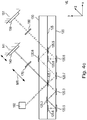
- FIGS. 4a-4d and 5a-5c A second embodiment of the interferometer according to the invention explained.
- the representations of the beam paths in these figures correspond to the representation system of the first embodiment.
- the relevant differences to the first exemplary embodiment are primarily described.
- first plane plate 120, second plane plate 125 and third plane plate 130 are hereinafter referred to as first plane plate 120, second plane plate 125 and third plane plate 130.
- first plane plate 120, second plane plate 125 and third plane plate 130 are hereinafter referred to as first plane plate 120, second plane plate 125 and third plane plate 130.
- the thickness of such thin plane plates 120, 125, 130 is preferably in the range of 0.5 - 3 mm; the dimensions of the thin flat plates 120, 125, 130 along the x and y direction correspond to the dimensions of the flat plates 20, 30 of the first embodiment.
- spacers are arranged between the three plane plates 120, 125, 130, which have corresponding recesses in the region of the beam propagating between the plane plates 120, 125, 130. These spacers are in the FIGS. 4a-4d again not shown for reasons of clarity.
- the beam paths of the radiation beam S emitted by the light source 110, the beam paths of the measurement and reference beam M, R in the measurement and reference arm and the beam path after reunification correspond in principle to the beam paths from the first exemplary embodiment.
- the beam paths in the measuring and reference arm between splitting and reuniting in the form of light plans are outlined below; the reference numerals used here can be found in the FIGS. 4a-4d and 5a-5c.
- optical effects of the different imaging optics on the measurement beam M and the reference beam R correspond to the optical effects of the respective analog imaging optics of the first embodiment. Also in this embodiment, the intrinsic compensation of possible tilting of the measuring and / or reference reflector is thus ensured.
- the interferometer according to the invention it is also possible to realize a mixed form of the interferometer according to the invention from the first and second exemplary embodiments.
Claims (14)
- Interféromètre comprenant- une source de lumière (10 ; 110),- un premier séparateur de faisceaux (30.1 ; 125.1) qui dissocie un faisceau de rayons (S) émis par la source de lumière (10 ; 110) en au moins un faisceau de rayons de mesure (M) et au moins un faisceau de rayons de référence (R), par lesquels est couvert un plan de dissociation (AE) et le faisceau de rayons de mesure (M) se propageant dans un bras de mesure et le faisceau de rayons de référence (R) dans un bras de référence jusqu'à la recombinaison en un point de jonction dans un plan de jonction (VE), le plan de jonction (VE) étant orienté parallèlement au plan de dissociation (AE),- un réflecteur de référence (50 ; 150) qui est disposé dans le bras de référence, le faisceau de rayons de référence (R) étant au moins trois fois incident sur le réflecteur de référence (50 ; 150),- un réflecteur de mesure (40 ; 140), lequel est disposé dans le bras de mesure et peut être relié à un objet à mesurer (41 ; 141), le faisceau de rayons de mesure (M) étant au moins trois fois incident sur le réflecteur de mesure (40 ; 140),- une unité de détection (60 ; 160) par le biais de laquelle peut être détecté au moins un signal de distance à partir des faisceaux de rayons de mesure et de référence (M, R) interférants superposés au niveau du point de jonction concernant la position de l'objet à mesurer (41 ; 141),- au moins deux plaques planes (20, 30 ; 120, 125, 130) transparentes qui sont disposées l'une derrière l'autre dans le sens de propagation du faisceau et parallèlement l'une à l'autre successivement l'une derrière l'autre dans le trajet du faisceau entre la source de lumière (10 ; 110) et l'unité de détection (60 ; 160), au moins le réflecteur de mesure (40 ; 140) étant mobile le long d'une direction de mesure (MR) par rapport aux plaques planes (20, 30 ; 120, 125, 130) et au réflecteur de référence (50 ; 150), la direction de mesure (MR) correspondant au sens de propagation du faisceau entre les plaques planes (20, 30) et le réflecteur de mesure (40 ; 140) et les plaques planes (20, 30 ; 120, 125, 130) comportant respectivement plusieurs éléments optiques qui exercent un effet optique tel sur le faisceau de rayons de mesure (M) et sur le faisceau de rayons de référence (R) que le faisceau de rayons de mesure (M) et le faisceau de rayons de référence (R) se propagent respectivement en parallèle l'un de l'autre en direction du réflecteur de mesure et de référence (40, 40 ; 140, 150) et- plusieurs réflecteurs et au moins quatre optiques de représentation pour le faisceau de rayons de mesure (M) et le faisceau de rayons de référence (R) étant formés en tant qu'éléments optiques dans les deux plaques planes (20, 30 ; 120, 125, 130) et- deux des au moins quatre optiques de représentation produisant respectivement un décalage du faisceau de rayons de mesure (M) et du faisceau de rayons de référence (R) du plan de dissociation (AE) dans un plan intermédiaire (ZE) qui se situe entre le plan de dissociation (AE) et le plan de jonction (VE) et qui est orienté parallèlement à ceux-ci et- deux des au moins quatre optiques de représentation produisant respectivement un décalage du faisceau de rayons de mesure (M) et du faisceau de rayons de référence (R) du plan intermédiaire (ZE) dans le plan de jonction (VE).
- Interféromètre selon la revendication 1, comprenant deux plaques planes,- une première optique de représentation pour le faisceau de rayons de mesure (M) étant disposée dans la deuxième plaque plane (30),- une deuxième optique de représentation pour le faisceau de rayons de mesure (M) étant disposée dans la première plaque plane (20),- une troisième optique de représentation pour le faisceau de rayons de référence (M) étant disposée dans la deuxième plaque plane (30) et- une quatrième optique de représentation pour le faisceau de rayons de référence (M) étant disposée dans la première plaque plane (20)et- les première et troisième optiques de représentation produisant en outre une augmentation du diamètre du rayon d'entrée du faisceau de rayons incident sur celles-ci et- les deuxième et quatrième optiques de représentation produisant en outre une réduction du diamètre du rayon du faisceau de rayons incident sur celles-ci au diamètre du rayon d'entrée.
- Interféromètre selon la revendication 2, les optiques de représentation comprenant respectivement deux lentilles à réseau (30.2, 30.7, 20.5, 20.9, 30.5, 30.9, 20.7, 20.11) réfléchissantes disposées sur un côté d'une plaque plane (20, 30) et un réflecteur (30.3, 20.6, 30.6, 20.8) disposé sur le côté opposé de la plaque plane (20, 30), les côtés réfléchissants des lentilles à réseau (30.2, 30.7, 20.5, 20.9, 30.5, 30.9, 20.7, 20.11) et du réflecteur (30.3, 20.6, 30.6, 20.8) se faisant mutuellement face.
- Interféromètre selon la revendication 3,- la première optique de représentation- possédant une première lentille à réseau (30.2) et une deuxième lentille à réseau (30.7), lesquelles sont toutes deux disposées sur un côté (30_B) de la deuxième plaque plane (30) et- possédant un premier réflecteur (30.3) disposé sur le côté opposé (30_A) de la deuxième plaque plane (30),- la première optique de représentation produisant un doublement du diamètre du rayon d'entrée du faisceau de rayons de mesure (M) incident sur celle-ci et- la deuxième optique de représentation- possédant une troisième lentille à réseau (20.5) et une quatrième lentille à réseau (20.9), lesquelles sont toutes deux disposées sur un côté (20_A) de la première plaque plane (20) et- possédant un deuxième réflecteur (20.6) disposé sur le côté opposé (20_B) de la première plaque plane (20),- la deuxième optique de représentation produisant une division par deux du diamètre du rayon d'entrée du faisceau de rayons de mesure (M) incident sur celle-ci et- la troisième optique de représentation- possédant une cinquième lentille à réseau (30.5) et une sixième lentille à réseau (30.9), lesquelles sont toutes deux disposées sur un côté (30_B) de la deuxième plaque plane (30) et- possédant un troisième réflecteur (30.6) disposé sur le côté opposé (30_A) de la deuxième plaque plane (30),- la troisième optique de représentation produisant un doublement du diamètre du rayon d'entrée du faisceau de rayons de référence (R) incident sur celle-ci et- la quatrième optique de représentation- possédant une septième lentille à réseau (20.7) et une huitième lentille à réseau (20.11), lesquelles sont toutes deux disposées sur un côté (20_A) de la première plaque plane (20) et- possédant un quatrième réflecteur (20.8) disposé sur le côté opposé (20_B) de la première plaque plane (20),- la quatrième optique de représentation produisant une division par deux du diamètre du rayon d'entrée du faisceau de rayons de référence (R) incident sur celle-ci.
- Interféromètre selon la revendication 4, les première, quatrième, cinquième et huitième lentilles à réseau (30.2, 20.9, 30.5, 20.11) possédant respectivement une première distance focale (f) et les deuxième, troisième, sixième et septième lentilles à réseau (30.7, 20.5, 30.9, 20.7) possédant respectivement une deuxième distance focale (2f) qui est égale au double de la première distance focale (f).
- Interféromètre selon la revendication 1, comprenant trois plaques planes disposées de manière espacée dans le sens de propagation du faisceau,- une première optique de représentation pour le faisceau de rayons de mesure (M) étant réalisée dans la deuxième et la troisième plaque plane (125, 130),- une deuxième optique de représentation pour le faisceau de rayons de mesure (M) étant réalisée dans la deuxième et la troisième plaque plane (125, 130),- une troisième optique de représentation pour le faisceau de rayons de référence (R) étant réalisée dans la première et la deuxième plaque plane (120, 125) et- une quatrième optique de représentation pour le faisceau de rayons de référence (R) étant réalisée dans la première et la deuxième plaque plane (120, 125) et- les première et troisième optiques de représentation produisant en outre une augmentation du diamètre du rayon d'entrée du faisceau de rayons incident sur celles-ci et- les deuxième et quatrième optiques de représentation produisant en outre une réduction du diamètre du rayon du faisceau de rayons incident sur celles-ci au diamètre du rayon d'entrée.
- Interféromètre selon la revendication 6, les optiques de représentation comprenant respectivement deux lentilles à réseau (130.2, 130.4, 120.4, 120.5, 130.3, 130.5, 120.6, 120.8) réfléchissantes disposées sur une plaque plane (120, 130) et un réflecteur (130.3, 120.6, 130.6, 120.8) disposé sur la plaque plane (125) opposée, les côtés réfléchissants des lentilles à réseau (130.2, 130.4, 120.4, 120.5, 130.3, 130.5, 120.6, 120.8) et du réflecteur (130.3, 120.6, 130.6, 120.8) se faisant mutuellement face.
- Interféromètre selon la revendication 7,- la première optique de représentation- possédant une première lentille à réseau (130.2) et une deuxième lentille à réseau (130.4) qui sont toutes deux disposées sur la troisième plaque plane (130) et- possédant un premier réflecteur (125.3) disposé sur la deuxième plaque plane (125),- la première optique de représentation produisant un doublement du diamètre du rayon d'entrée du faisceau de rayons de mesure (M) incident sur celle-ci et- la deuxième optique de représentation- possédant une troisième lentille à réseau (120.4) et une quatrième lentille à réseau (120.5) qui sont toutes deux disposées sur la première plaque plane (120) et- possédant un deuxième réflecteur (125.6) disposé sur la deuxième plaque plane (125),- la deuxième optique de représentation produisant une division par deux du diamètre du rayon du faisceau de rayons de mesure (M) incident sur celle-ci et- la troisième optique de représentation- possédant une cinquième lentille à réseau (130.3) et une sixième lentille à réseau (130.5) qui sont toutes deux disposées sur la troisième plaque plane (130) et- possédant un troisième réflecteur (125.7) disposé sur la deuxième plaque plane (125),- la troisième optique de représentation produisant un doublement du diamètre du rayon d'entrée du faisceau de rayons de référence (R) incident sur celle-ci et- la quatrième optique de représentation- possédant une septième lentille à réseau (120.6) et une huitième lentille à réseau (120.8) qui sont toutes deux disposées sur la première plaque plane (120) et- possédant un quatrième réflecteur (125.8) disposé sur la deuxième plaque plane (125),- la quatrième optique de représentation produisant une division par deux du diamètre du rayon du faisceau de rayons de référence (R) incident sur celle-ci.
- Interféromètre selon la revendication 8, les première, quatrième, cinquième et huitième lentilles à réseau (130.2, 120.5, 130.3, 120.8) possédant respectivement une première distance focale (f) et les deuxième, troisième, sixième et septième lentilles à réseau (130.4, 120.4, 130.5, 120.6) possédant respectivement une deuxième distance focale (2f) qui est égale au double de la première distance focale (f).
- Interféromètre selon au moins l'une des revendications précédentes, le premier séparateur de faisceaux (30.1 ; 125.1) sur la deuxième plaque plane (30 ; 130) étant réalisé sous la forme d'une grille ou d'une couche séparatrice de faisceaux optique polarisante lesquels sont respectivement disposés sur un côté (30_A) de la deuxième plaque plane (30 ; 125) qui est orienté en direction de la première plaque plane (20 ; 120).
- Interféromètre selon au moins l'une des revendications précédentes, le réflecteur de mesure (40 ; 140) et le réflecteur de référence (50 ; 150) étant respectivement réalisés sous la forme d'un réflecteur à miroir plan.
- Interféromètre selon au moins l'une des revendications précédentes, un segment de ralentissement étant configuré dans le trajet du rayon du faisceau de rayons de mesure (M) de telle sorte que le faisceau de rayons de mesure (M) et le faisceau de rayons de référence (R), entre la dissociation et la recombinaison, traversent des trajets optiques identiques dans l'air et dans les plaques planes (20, 30).
- Interféromètre selon au moins l'une des revendications précédentes,- le faisceau de rayons de mesure (M) est incident perpendiculairement sur le réflecteur de mesure (40 ; 140) lors de la deuxième incidence et- le faisceau de rayons de référence (R) est incident perpendiculairement sur le réflecteur de référence (50 ; 150) lors de la deuxième incidence.
- Interféromètre selon au moins l'une des revendications précédentes, des entretoises étant disposées entre les plaques planes, lesquelles possèdent des cavités dans la zone des faisceaux de rayons de mesure et de référence qui se propagent entre les plaques planes.
Applications Claiming Priority (1)
| Application Number | Priority Date | Filing Date | Title |
|---|---|---|---|
| DE102014214839.1A DE102014214839A1 (de) | 2014-07-29 | 2014-07-29 | Interferometer |
Publications (2)
| Publication Number | Publication Date |
|---|---|
| EP2980525A1 EP2980525A1 (fr) | 2016-02-03 |
| EP2980525B1 true EP2980525B1 (fr) | 2018-12-19 |
Family
ID=53546150
Family Applications (1)
| Application Number | Title | Priority Date | Filing Date |
|---|---|---|---|
| EP15176437.0A Active EP2980525B1 (fr) | 2014-07-29 | 2015-07-13 | Interferometre à triple passage |
Country Status (4)
| Country | Link |
|---|---|
| US (1) | US9797704B2 (fr) |
| EP (1) | EP2980525B1 (fr) |
| CN (1) | CN105509634B (fr) |
| DE (1) | DE102014214839A1 (fr) |
Families Citing this family (5)
| Publication number | Priority date | Publication date | Assignee | Title |
|---|---|---|---|---|
| US9767687B2 (en) | 2015-09-11 | 2017-09-19 | Sony Corporation | System and method for driving assistance along a path |
| JP6400035B2 (ja) * | 2016-03-14 | 2018-10-03 | キヤノン株式会社 | 位置検出装置、力覚センサ、および、装置 |
| CN107560562B (zh) * | 2016-06-30 | 2019-10-25 | 上海微电子装备(集团)股份有限公司 | 一种干涉式微观形貌测量系统及方法 |
| TWI583982B (zh) * | 2016-09-26 | 2017-05-21 | 峰安車業股份有限公司 | 位移量測裝置及加工系統 |
| CN113325579A (zh) * | 2020-02-28 | 2021-08-31 | 苏州苏大维格科技集团股份有限公司 | 用于呈现增强现实图像的装置和包含该装置的系统 |
Family Cites Families (13)
| Publication number | Priority date | Publication date | Assignee | Title |
|---|---|---|---|---|
| US4752133A (en) | 1985-12-19 | 1988-06-21 | Zygo Corporation | Differential plane mirror interferometer |
| US4746216A (en) * | 1986-03-28 | 1988-05-24 | Zygo Corporation | Angle measuring interferometer |
| US5187543A (en) * | 1990-01-19 | 1993-02-16 | Zygo Corporation | Differential displacement measuring interferometer |
| DE10317387B4 (de) * | 2002-04-18 | 2007-05-24 | Agilent Technologies, Inc. (n.d.Ges.d.Staates Delaware), Palo Alto | Kompakte Strahlzurückverfolgungsoptikeinrichtung zum Eliminieren eines Strahlauseinanderlaufens |
| US6897962B2 (en) * | 2002-04-18 | 2005-05-24 | Agilent Technologies, Inc. | Interferometer using beam re-tracing to eliminate beam walk-off |
| US7046370B2 (en) * | 2002-06-24 | 2006-05-16 | Zygo Corporation | Interferometer with reduced shear |
| US7088450B2 (en) * | 2003-04-03 | 2006-08-08 | Coherent, Inc. | Method and apparatus for measuring amplified stimulated emission in the output of a master oscillator power amplifier system |
| US7212290B2 (en) * | 2004-07-28 | 2007-05-01 | Agilent Technologies, Inc. | Differential interferometers creating desired beam patterns |
| DE102004049646B4 (de) * | 2004-10-11 | 2018-05-03 | Dr. Johannes Heidenhain Gmbh | Optik-Baugruppe für ein Interferometer |
| DE102007035345A1 (de) * | 2006-11-20 | 2008-05-21 | Dr. Johannes Heidenhain Gmbh | Positionsmesseinrichtung |
| US8004749B1 (en) * | 2008-07-19 | 2011-08-23 | Optoplex Corporation | Pseudo common-path DPSK demodulator |
| DE102011005937B4 (de) * | 2011-03-23 | 2020-10-22 | Dr. Johannes Heidenhain Gmbh | Vorrichtung zur interferentiellen Abstandsmessung |
| DE102013211758A1 (de) * | 2013-06-21 | 2014-12-24 | Dr. Johannes Heidenhain Gmbh | Interferometer |
-
2014
- 2014-07-29 DE DE102014214839.1A patent/DE102014214839A1/de not_active Withdrawn
-
2015
- 2015-07-13 EP EP15176437.0A patent/EP2980525B1/fr active Active
- 2015-07-24 US US14/809,107 patent/US9797704B2/en active Active
- 2015-07-29 CN CN201510453259.6A patent/CN105509634B/zh active Active
Non-Patent Citations (1)
| Title |
|---|
| None * |
Also Published As
| Publication number | Publication date |
|---|---|
| CN105509634B (zh) | 2019-09-20 |
| EP2980525A1 (fr) | 2016-02-03 |
| CN105509634A (zh) | 2016-04-20 |
| DE102014214839A1 (de) | 2016-02-04 |
| US9797704B2 (en) | 2017-10-24 |
| US20160033257A1 (en) | 2016-02-04 |
Similar Documents
| Publication | Publication Date | Title |
|---|---|---|
| EP2980525B1 (fr) | Interferometre à triple passage | |
| EP2816316B1 (fr) | Interféromètre | |
| EP2955489B1 (fr) | Dispositif optique de mesure de position | |
| EP1373966B1 (fr) | Dispositif de formation de faisceau, systeme permettant d'injecter un faisceau lumineux dans une fibre optique et unite de rotation de faisceau destinee a un tel dispositif de formation de faisceau ou a un tel systeme | |
| EP2565578B1 (fr) | Dispositif interférométrique de détermination de distance entre deux plaques parallèles | |
| EP3059554B1 (fr) | Dispositif optique de mesure de position | |
| EP1793269B1 (fr) | Dispositif destiné à influencer la lumière | |
| EP1031868A1 (fr) | Séparateur parallêle de faisceaux compensés avec deux plaques et interféromètre | |
| EP3258220B1 (fr) | Dispositif optique de mesure de position | |
| DE102011076178A1 (de) | Positionsmesseinrichtung | |
| WO2018141333A1 (fr) | Dispositif pour l'augmentation de la résolution d'un microscope à balayage laser | |
| EP2746731B1 (fr) | Dispositif optique de mesure de la position | |
| DE102011005937B4 (de) | Vorrichtung zur interferentiellen Abstandsmessung | |
| EP1329760A2 (fr) | Apareil de réduction de cohérence | |
| EP2869034B1 (fr) | Dispositif de détermination de la position | |
| DE102004049646A1 (de) | Optik-Baugruppe für ein Interferometer | |
| EP1384105B1 (fr) | Dispositif de modelage de faisceau permettant le modelage de la section d'un faisceau lumineux | |
| EP2813802B1 (fr) | Dispositif de mesure | |
| WO2014170066A1 (fr) | Dispositif de mesure de distance interférentielle | |
| EP3555687A1 (fr) | Dispositif pour dévier et/ou moduler un rayonnement laser, notamment une pluralité de faisceaux laser | |
| DE102020210369B3 (de) | Verfahren, Optische Vorrichtung, Lichtblattmikroskop und Nachrüstsatz zur Erzeugung von Lichtblättern mittels eines Retroreflektors | |
| DE102008036572B4 (de) | Vorrichtung zum Bearbeiten von optischen Impulsen | |
| DE10308006A1 (de) | Michelson-Interferometer | |
| DE4026333A1 (de) | Vorrichtung zur symmetrisierung eines fluchtstrahls mit einem strahlteiler | |
| DE19958555A1 (de) | Strahlteilerbaugruppe sowie Interferometer mit einer Strahlteilerbaugruppe |
Legal Events
| Date | Code | Title | Description |
|---|---|---|---|
| PUAI | Public reference made under article 153(3) epc to a published international application that has entered the european phase |
Free format text: ORIGINAL CODE: 0009012 |
|
| AK | Designated contracting states |
Kind code of ref document: A1 Designated state(s): AL AT BE BG CH CY CZ DE DK EE ES FI FR GB GR HR HU IE IS IT LI LT LU LV MC MK MT NL NO PL PT RO RS SE SI SK SM TR |
|
| AX | Request for extension of the european patent |
Extension state: BA ME |
|
| 17P | Request for examination filed |
Effective date: 20160803 |
|
| RBV | Designated contracting states (corrected) |
Designated state(s): AL AT BE BG CH CY CZ DE DK EE ES FI FR GB GR HR HU IE IS IT LI LT LU LV MC MK MT NL NO PL PT RO RS SE SI SK SM TR |
|
| GRAP | Despatch of communication of intention to grant a patent |
Free format text: ORIGINAL CODE: EPIDOSNIGR1 |
|
| STAA | Information on the status of an ep patent application or granted ep patent |
Free format text: STATUS: GRANT OF PATENT IS INTENDED |
|
| INTG | Intention to grant announced |
Effective date: 20180906 |
|
| GRAS | Grant fee paid |
Free format text: ORIGINAL CODE: EPIDOSNIGR3 |
|
| GRAA | (expected) grant |
Free format text: ORIGINAL CODE: 0009210 |
|
| STAA | Information on the status of an ep patent application or granted ep patent |
Free format text: STATUS: THE PATENT HAS BEEN GRANTED |
|
| AK | Designated contracting states |
Kind code of ref document: B1 Designated state(s): AL AT BE BG CH CY CZ DE DK EE ES FI FR GB GR HR HU IE IS IT LI LT LU LV MC MK MT NL NO PL PT RO RS SE SI SK SM TR |
|
| REG | Reference to a national code |
Ref country code: GB Ref legal event code: FG4D Free format text: NOT ENGLISH |
|
| REG | Reference to a national code |
Ref country code: CH Ref legal event code: EP |
|
| REG | Reference to a national code |
Ref country code: IE Ref legal event code: FG4D Free format text: LANGUAGE OF EP DOCUMENT: GERMAN |
|
| REG | Reference to a national code |
Ref country code: DE Ref legal event code: R096 Ref document number: 502015007303 Country of ref document: DE |
|
| REG | Reference to a national code |
Ref country code: AT Ref legal event code: REF Ref document number: 1079199 Country of ref document: AT Kind code of ref document: T Effective date: 20190115 |
|
| REG | Reference to a national code |
Ref country code: NL Ref legal event code: FP |
|
| PG25 | Lapsed in a contracting state [announced via postgrant information from national office to epo] |
Ref country code: FI Free format text: LAPSE BECAUSE OF FAILURE TO SUBMIT A TRANSLATION OF THE DESCRIPTION OR TO PAY THE FEE WITHIN THE PRESCRIBED TIME-LIMIT Effective date: 20181219 Ref country code: HR Free format text: LAPSE BECAUSE OF FAILURE TO SUBMIT A TRANSLATION OF THE DESCRIPTION OR TO PAY THE FEE WITHIN THE PRESCRIBED TIME-LIMIT Effective date: 20181219 Ref country code: LV Free format text: LAPSE BECAUSE OF FAILURE TO SUBMIT A TRANSLATION OF THE DESCRIPTION OR TO PAY THE FEE WITHIN THE PRESCRIBED TIME-LIMIT Effective date: 20181219 Ref country code: LT Free format text: LAPSE BECAUSE OF FAILURE TO SUBMIT A TRANSLATION OF THE DESCRIPTION OR TO PAY THE FEE WITHIN THE PRESCRIBED TIME-LIMIT Effective date: 20181219 Ref country code: NO Free format text: LAPSE BECAUSE OF FAILURE TO SUBMIT A TRANSLATION OF THE DESCRIPTION OR TO PAY THE FEE WITHIN THE PRESCRIBED TIME-LIMIT Effective date: 20190319 Ref country code: BG Free format text: LAPSE BECAUSE OF FAILURE TO SUBMIT A TRANSLATION OF THE DESCRIPTION OR TO PAY THE FEE WITHIN THE PRESCRIBED TIME-LIMIT Effective date: 20190319 |
|
| REG | Reference to a national code |
Ref country code: LT Ref legal event code: MG4D |
|
| PG25 | Lapsed in a contracting state [announced via postgrant information from national office to epo] |
Ref country code: RS Free format text: LAPSE BECAUSE OF FAILURE TO SUBMIT A TRANSLATION OF THE DESCRIPTION OR TO PAY THE FEE WITHIN THE PRESCRIBED TIME-LIMIT Effective date: 20181219 Ref country code: AL Free format text: LAPSE BECAUSE OF FAILURE TO SUBMIT A TRANSLATION OF THE DESCRIPTION OR TO PAY THE FEE WITHIN THE PRESCRIBED TIME-LIMIT Effective date: 20181219 Ref country code: SE Free format text: LAPSE BECAUSE OF FAILURE TO SUBMIT A TRANSLATION OF THE DESCRIPTION OR TO PAY THE FEE WITHIN THE PRESCRIBED TIME-LIMIT Effective date: 20181219 Ref country code: GR Free format text: LAPSE BECAUSE OF FAILURE TO SUBMIT A TRANSLATION OF THE DESCRIPTION OR TO PAY THE FEE WITHIN THE PRESCRIBED TIME-LIMIT Effective date: 20190320 |
|
| PG25 | Lapsed in a contracting state [announced via postgrant information from national office to epo] |
Ref country code: CZ Free format text: LAPSE BECAUSE OF FAILURE TO SUBMIT A TRANSLATION OF THE DESCRIPTION OR TO PAY THE FEE WITHIN THE PRESCRIBED TIME-LIMIT Effective date: 20181219 Ref country code: PT Free format text: LAPSE BECAUSE OF FAILURE TO SUBMIT A TRANSLATION OF THE DESCRIPTION OR TO PAY THE FEE WITHIN THE PRESCRIBED TIME-LIMIT Effective date: 20190419 Ref country code: ES Free format text: LAPSE BECAUSE OF FAILURE TO SUBMIT A TRANSLATION OF THE DESCRIPTION OR TO PAY THE FEE WITHIN THE PRESCRIBED TIME-LIMIT Effective date: 20181219 Ref country code: PL Free format text: LAPSE BECAUSE OF FAILURE TO SUBMIT A TRANSLATION OF THE DESCRIPTION OR TO PAY THE FEE WITHIN THE PRESCRIBED TIME-LIMIT Effective date: 20181219 Ref country code: IT Free format text: LAPSE BECAUSE OF FAILURE TO SUBMIT A TRANSLATION OF THE DESCRIPTION OR TO PAY THE FEE WITHIN THE PRESCRIBED TIME-LIMIT Effective date: 20181219 |
|
| PG25 | Lapsed in a contracting state [announced via postgrant information from national office to epo] |
Ref country code: SK Free format text: LAPSE BECAUSE OF FAILURE TO SUBMIT A TRANSLATION OF THE DESCRIPTION OR TO PAY THE FEE WITHIN THE PRESCRIBED TIME-LIMIT Effective date: 20181219 Ref country code: RO Free format text: LAPSE BECAUSE OF FAILURE TO SUBMIT A TRANSLATION OF THE DESCRIPTION OR TO PAY THE FEE WITHIN THE PRESCRIBED TIME-LIMIT Effective date: 20181219 Ref country code: IS Free format text: LAPSE BECAUSE OF FAILURE TO SUBMIT A TRANSLATION OF THE DESCRIPTION OR TO PAY THE FEE WITHIN THE PRESCRIBED TIME-LIMIT Effective date: 20190419 Ref country code: EE Free format text: LAPSE BECAUSE OF FAILURE TO SUBMIT A TRANSLATION OF THE DESCRIPTION OR TO PAY THE FEE WITHIN THE PRESCRIBED TIME-LIMIT Effective date: 20181219 Ref country code: SM Free format text: LAPSE BECAUSE OF FAILURE TO SUBMIT A TRANSLATION OF THE DESCRIPTION OR TO PAY THE FEE WITHIN THE PRESCRIBED TIME-LIMIT Effective date: 20181219 |
|
| REG | Reference to a national code |
Ref country code: DE Ref legal event code: R097 Ref document number: 502015007303 Country of ref document: DE |
|
| PLBE | No opposition filed within time limit |
Free format text: ORIGINAL CODE: 0009261 |
|
| STAA | Information on the status of an ep patent application or granted ep patent |
Free format text: STATUS: NO OPPOSITION FILED WITHIN TIME LIMIT |
|
| PG25 | Lapsed in a contracting state [announced via postgrant information from national office to epo] |
Ref country code: DK Free format text: LAPSE BECAUSE OF FAILURE TO SUBMIT A TRANSLATION OF THE DESCRIPTION OR TO PAY THE FEE WITHIN THE PRESCRIBED TIME-LIMIT Effective date: 20181219 |
|
| 26N | No opposition filed |
Effective date: 20190920 |
|
| PG25 | Lapsed in a contracting state [announced via postgrant information from national office to epo] |
Ref country code: SI Free format text: LAPSE BECAUSE OF FAILURE TO SUBMIT A TRANSLATION OF THE DESCRIPTION OR TO PAY THE FEE WITHIN THE PRESCRIBED TIME-LIMIT Effective date: 20181219 Ref country code: MC Free format text: LAPSE BECAUSE OF FAILURE TO SUBMIT A TRANSLATION OF THE DESCRIPTION OR TO PAY THE FEE WITHIN THE PRESCRIBED TIME-LIMIT Effective date: 20181219 |
|
| REG | Reference to a national code |
Ref country code: CH Ref legal event code: PL |
|
| GBPC | Gb: european patent ceased through non-payment of renewal fee |
Effective date: 20190713 |
|
| PG25 | Lapsed in a contracting state [announced via postgrant information from national office to epo] |
Ref country code: TR Free format text: LAPSE BECAUSE OF FAILURE TO SUBMIT A TRANSLATION OF THE DESCRIPTION OR TO PAY THE FEE WITHIN THE PRESCRIBED TIME-LIMIT Effective date: 20181219 |
|
| REG | Reference to a national code |
Ref country code: BE Ref legal event code: MM Effective date: 20190731 |
|
| PG25 | Lapsed in a contracting state [announced via postgrant information from national office to epo] |
Ref country code: GB Free format text: LAPSE BECAUSE OF NON-PAYMENT OF DUE FEES Effective date: 20190713 |
|
| PG25 | Lapsed in a contracting state [announced via postgrant information from national office to epo] |
Ref country code: CH Free format text: LAPSE BECAUSE OF NON-PAYMENT OF DUE FEES Effective date: 20190731 Ref country code: LU Free format text: LAPSE BECAUSE OF NON-PAYMENT OF DUE FEES Effective date: 20190713 Ref country code: LI Free format text: LAPSE BECAUSE OF NON-PAYMENT OF DUE FEES Effective date: 20190731 Ref country code: BE Free format text: LAPSE BECAUSE OF NON-PAYMENT OF DUE FEES Effective date: 20190731 |
|
| PG25 | Lapsed in a contracting state [announced via postgrant information from national office to epo] |
Ref country code: FR Free format text: LAPSE BECAUSE OF NON-PAYMENT OF DUE FEES Effective date: 20190731 |
|
| PG25 | Lapsed in a contracting state [announced via postgrant information from national office to epo] |
Ref country code: IE Free format text: LAPSE BECAUSE OF NON-PAYMENT OF DUE FEES Effective date: 20190713 |
|
| PG25 | Lapsed in a contracting state [announced via postgrant information from national office to epo] |
Ref country code: CY Free format text: LAPSE BECAUSE OF FAILURE TO SUBMIT A TRANSLATION OF THE DESCRIPTION OR TO PAY THE FEE WITHIN THE PRESCRIBED TIME-LIMIT Effective date: 20181219 |
|
| PG25 | Lapsed in a contracting state [announced via postgrant information from national office to epo] |
Ref country code: HU Free format text: LAPSE BECAUSE OF FAILURE TO SUBMIT A TRANSLATION OF THE DESCRIPTION OR TO PAY THE FEE WITHIN THE PRESCRIBED TIME-LIMIT; INVALID AB INITIO Effective date: 20150713 Ref country code: MT Free format text: LAPSE BECAUSE OF FAILURE TO SUBMIT A TRANSLATION OF THE DESCRIPTION OR TO PAY THE FEE WITHIN THE PRESCRIBED TIME-LIMIT Effective date: 20181219 |
|
| REG | Reference to a national code |
Ref country code: AT Ref legal event code: MM01 Ref document number: 1079199 Country of ref document: AT Kind code of ref document: T Effective date: 20200713 |
|
| PG25 | Lapsed in a contracting state [announced via postgrant information from national office to epo] |
Ref country code: AT Free format text: LAPSE BECAUSE OF NON-PAYMENT OF DUE FEES Effective date: 20200713 |
|
| PG25 | Lapsed in a contracting state [announced via postgrant information from national office to epo] |
Ref country code: MK Free format text: LAPSE BECAUSE OF FAILURE TO SUBMIT A TRANSLATION OF THE DESCRIPTION OR TO PAY THE FEE WITHIN THE PRESCRIBED TIME-LIMIT Effective date: 20181219 |
|
| PGFP | Annual fee paid to national office [announced via postgrant information from national office to epo] |
Ref country code: NL Payment date: 20230719 Year of fee payment: 9 |
|
| PGFP | Annual fee paid to national office [announced via postgrant information from national office to epo] |
Ref country code: DE Payment date: 20230719 Year of fee payment: 9 |