EP2980408A1 - Scroll compressor - Google Patents
Scroll compressor Download PDFInfo
- Publication number
- EP2980408A1 EP2980408A1 EP13880382.0A EP13880382A EP2980408A1 EP 2980408 A1 EP2980408 A1 EP 2980408A1 EP 13880382 A EP13880382 A EP 13880382A EP 2980408 A1 EP2980408 A1 EP 2980408A1
- Authority
- EP
- European Patent Office
- Prior art keywords
- orbiting
- fixed
- tooth bottom
- side wrap
- scroll
- Prior art date
- Legal status (The legal status is an assumption and is not a legal conclusion. Google has not performed a legal analysis and makes no representation as to the accuracy of the status listed.)
- Withdrawn
Links
Images



Classifications
-
- F—MECHANICAL ENGINEERING; LIGHTING; HEATING; WEAPONS; BLASTING
- F04—POSITIVE - DISPLACEMENT MACHINES FOR LIQUIDS; PUMPS FOR LIQUIDS OR ELASTIC FLUIDS
- F04C—ROTARY-PISTON, OR OSCILLATING-PISTON, POSITIVE-DISPLACEMENT MACHINES FOR LIQUIDS; ROTARY-PISTON, OR OSCILLATING-PISTON, POSITIVE-DISPLACEMENT PUMPS
- F04C18/00—Rotary-piston pumps specially adapted for elastic fluids
- F04C18/02—Rotary-piston pumps specially adapted for elastic fluids of arcuate-engagement type, i.e. with circular translatory movement of co-operating members, each member having the same number of teeth or tooth-equivalents
- F04C18/0207—Rotary-piston pumps specially adapted for elastic fluids of arcuate-engagement type, i.e. with circular translatory movement of co-operating members, each member having the same number of teeth or tooth-equivalents both members having co-operating elements in spiral form
- F04C18/0246—Details concerning the involute wraps or their base, e.g. geometry
- F04C18/0269—Details concerning the involute wraps
-
- F—MECHANICAL ENGINEERING; LIGHTING; HEATING; WEAPONS; BLASTING
- F04—POSITIVE - DISPLACEMENT MACHINES FOR LIQUIDS; PUMPS FOR LIQUIDS OR ELASTIC FLUIDS
- F04C—ROTARY-PISTON, OR OSCILLATING-PISTON, POSITIVE-DISPLACEMENT MACHINES FOR LIQUIDS; ROTARY-PISTON, OR OSCILLATING-PISTON, POSITIVE-DISPLACEMENT PUMPS
- F04C18/00—Rotary-piston pumps specially adapted for elastic fluids
- F04C18/02—Rotary-piston pumps specially adapted for elastic fluids of arcuate-engagement type, i.e. with circular translatory movement of co-operating members, each member having the same number of teeth or tooth-equivalents
- F04C18/0207—Rotary-piston pumps specially adapted for elastic fluids of arcuate-engagement type, i.e. with circular translatory movement of co-operating members, each member having the same number of teeth or tooth-equivalents both members having co-operating elements in spiral form
- F04C18/0215—Rotary-piston pumps specially adapted for elastic fluids of arcuate-engagement type, i.e. with circular translatory movement of co-operating members, each member having the same number of teeth or tooth-equivalents both members having co-operating elements in spiral form where only one member is moving
-
- F—MECHANICAL ENGINEERING; LIGHTING; HEATING; WEAPONS; BLASTING
- F04—POSITIVE - DISPLACEMENT MACHINES FOR LIQUIDS; PUMPS FOR LIQUIDS OR ELASTIC FLUIDS
- F04C—ROTARY-PISTON, OR OSCILLATING-PISTON, POSITIVE-DISPLACEMENT MACHINES FOR LIQUIDS; ROTARY-PISTON, OR OSCILLATING-PISTON, POSITIVE-DISPLACEMENT PUMPS
- F04C18/00—Rotary-piston pumps specially adapted for elastic fluids
- F04C18/02—Rotary-piston pumps specially adapted for elastic fluids of arcuate-engagement type, i.e. with circular translatory movement of co-operating members, each member having the same number of teeth or tooth-equivalents
- F04C18/0207—Rotary-piston pumps specially adapted for elastic fluids of arcuate-engagement type, i.e. with circular translatory movement of co-operating members, each member having the same number of teeth or tooth-equivalents both members having co-operating elements in spiral form
- F04C18/0246—Details concerning the involute wraps or their base, e.g. geometry
- F04C18/0269—Details concerning the involute wraps
- F04C18/0276—Different wall heights
-
- F—MECHANICAL ENGINEERING; LIGHTING; HEATING; WEAPONS; BLASTING
- F04—POSITIVE - DISPLACEMENT MACHINES FOR LIQUIDS; PUMPS FOR LIQUIDS OR ELASTIC FLUIDS
- F04C—ROTARY-PISTON, OR OSCILLATING-PISTON, POSITIVE-DISPLACEMENT MACHINES FOR LIQUIDS; ROTARY-PISTON, OR OSCILLATING-PISTON, POSITIVE-DISPLACEMENT PUMPS
- F04C29/00—Component parts, details or accessories of pumps or pumping installations, not provided for in groups F04C18/00 - F04C28/00
- F04C29/0042—Driving elements, brakes, couplings, transmissions specially adapted for pumps
- F04C29/005—Means for transmitting movement from the prime mover to driven parts of the pump, e.g. clutches, couplings, transmissions
-
- F—MECHANICAL ENGINEERING; LIGHTING; HEATING; WEAPONS; BLASTING
- F04—POSITIVE - DISPLACEMENT MACHINES FOR LIQUIDS; PUMPS FOR LIQUIDS OR ELASTIC FLUIDS
- F04C—ROTARY-PISTON, OR OSCILLATING-PISTON, POSITIVE-DISPLACEMENT MACHINES FOR LIQUIDS; ROTARY-PISTON, OR OSCILLATING-PISTON, POSITIVE-DISPLACEMENT PUMPS
- F04C29/00—Component parts, details or accessories of pumps or pumping installations, not provided for in groups F04C18/00 - F04C28/00
- F04C29/0042—Driving elements, brakes, couplings, transmissions specially adapted for pumps
- F04C29/0085—Prime movers
-
- F—MECHANICAL ENGINEERING; LIGHTING; HEATING; WEAPONS; BLASTING
- F04—POSITIVE - DISPLACEMENT MACHINES FOR LIQUIDS; PUMPS FOR LIQUIDS OR ELASTIC FLUIDS
- F04C—ROTARY-PISTON, OR OSCILLATING-PISTON, POSITIVE-DISPLACEMENT MACHINES FOR LIQUIDS; ROTARY-PISTON, OR OSCILLATING-PISTON, POSITIVE-DISPLACEMENT PUMPS
- F04C2230/00—Manufacture
- F04C2230/60—Assembly methods
- F04C2230/602—Gap; Clearance
Definitions
- the present invention relates to a scroll compressor.
- Patent Literature 1 Japanese Patent No. 2009-281509 as background art of the subject technical field discloses that "There is an inclined surface having the plate thickness reduced from the outer peripheral side to the inner peripheral side preliminarily formed on the surface of the mirror plate of the orbiting scroll, which faces the mirror plate of the fixed scroll in expectation of the scroll deformation.
- the fixed scroll has a spiral wrap standing on the inner periphery of the flat plate, and a cylindrical mirror plate mounted on the outer periphery to surround the wrap.
- the orbiting scroll has a standing spiral wrap in mesh with the fixed scroll wrap on the mirror plate opposite the fixed scroll at the side of the standing wrap to form a plurality of compression chambers.” This makes it possible to "improve efficiency of the compressor by reducing the friction loss caused by deformations of the fixed scroll and the orbiting scroll" (see abstract).
- Patent Literature 1 discloses that the tooth bottoms are preliminarily formed on opposite surfaces of mirror plates of the orbiting scroll and the fixed scroll, each step of which has the depth increased from the outer peripheral side to the inner peripheral side in expectation of the scroll deformation, reducing the friction loss caused by the contact between the wrap tooth tip and the opposing tooth bottom.
- the thus formed tooth bottom step may suppress the contact between the wrap tooth tip and the tooth bottom. If the tooth bottom step is unnecessarily widened, the gap is generated, through which gas leaks to the inside of the compression chamber, thus increasing the loss.
- the present invention includes a plurality of means for solving the problem, one of which will be described as an example below.
- the present invention provides a scroll compressor which includes a fixed scroll including a fixed-side plate and a fixed-side wrap standing on one surface of the fixed-side plate while retaining a spiral shape, an orbiting scroll including an orbiting-side plate, and an orbiting-side wrap standing on one surface of the orbiting-side plate while retaining a spiral shape, which allows the orbiting-side wrap to be in mesh with the fixed-side wrap for orbiting with respect to the fixed scroll to form a compression chamber, and an electric motor for driving the orbiting scroll via a crankshaft.
- Each tooth bottom of the fixed-side wrap and the orbiting-side wrap has a step formed to become deeper from an outer periphery to an inner periphery. The step is formed on the tooth bottom of the fixed-side wrap at the inner periphery so as to be deeper than the step formed on the tooth bottom of the orbiting-side wrap at the inner periphery.
- the present invention is capable of suppressing the contact between the wrap tooth tip and the tooth bottom by forming the tooth bottom step, and reducing the loss caused by the gap generated as a result of enlarging the tooth bottom step.
- scroll compressor which is configured to optimize the gap between wraps so as to suppress the load exerted to the wrap and to reduce the loss caused by leakage into the compression chamber.
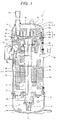
- Fig. 1 shows an example of the structure of the scroll compressor according to the embodiment.
- a scroll compressor 1 includes a compression mechanism part 2, an electric motor 3 for driving the compression mechanism part 2, and a closed vessel 4 for storing the compression mechanism part 2 and the electric motor 3.
- the embodiment is formed as a vertical scroll compressor configured to have the compression mechanism part 2 disposed at the upper section in the closed vessel 2, the electric motor 3 disposed in the intermediate section, and an oil sump 15 disposed at the lower section of the closed vessel 4.
- the closed vessel 4 is formed by welding a lid cap 4b and a bottom cap 4c to top and bottom parts of a cylindrical chamber 4a.
- An intake pipe 4d is mounted to the lid cap 4b, and a discharge pipe 4e is mounted to the side surface of the cylindrical chamber 4a.
- the closed vessel 4 has discharge pressure space 4f working as the discharge pressure therein.
- the compression mechanism part 2 and the electric motor 3 are stored in the discharge pressure space 4f.
- the compression mechanism part 2 includes a fixed scroll 5, an orbiting scroll 6, and a frame 7 as basic components.
- the fixed scroll 5 and the frame 7 are secured with a bolt, and the orbiting scroll 6 is supported with the frame 7.
- Fig. 2 shows cross-sections of basic structures of the fixed scroll 5 and the orbiting scroll 6 of the scroll compressor 1 according to the embodiment. Referring to Fig. 2 , consistency does not necessarily exist in the relative dimension ratio between the fixed scroll 5 and the orbiting scroll 6.
- the fixed scroll 5 includes a disc-like top plate (fixed-side plate 5b), a spiral fixed-side wrap 5a which stands on the inner periphery at the lower section of the fixed-side plate 5b, a cylindrical fixed-side mirror plate 5g disposed on the outer periphery of the fixed-side plate 5b to surround the wrap 5a, and an intake port 5c and a discharge port 5d which are provided at the upper section of the fixed-side plate 5b.
- the fixed scroll as described above is secured to the frame 7 with the bolt.
- the orbiting scroll 6 includes a disc-like orbiting-side plate 6b, and a spiral orbiting-side wrap 6a, standing on the inner periphery of the orbiting-side plate 6b at the side where the fixed-side wrap 5a of the fixed scroll 5 stands.
- the orbiting scroll 6 is orbitally arranged so as to allow the wrap to be in mesh with the wrap of the fixed scroll 5 to form compression chambers 16.
- An eccentric pin 9b of a crankshaft 9 is connected to a back surface side of the orbiting scroll 6 (the lower side as shown in Figs. 1 and 2 ). The orbiting motion of the orbiting scroll 6 with respect to the fixed scroll 5 ensures compression to reduce the volume thereof.
- Each scroll wrap (fixed-side wrap 5a, orbiting-side wrap 6a) is formed of an involute curve of the circle as the basic curve, and has an asymmetrical scroll shape, having a compression chamber at the outer line side formed outside the wrap at a winding end side of the orbiting scroll 6 and a compression chamber at the inner line side formed inside the wrap each having the different size in the state where both scrolls are meshed with each other, and each phase is shifted at approximately 180° with respect to rotation of the shaft.
- the outer periphery of the frame 7 is secured to an inner wall surface of the closed vessel 4 through welding, and provided with a main bearing 8 which supports the crankshaft 9 rotatably.
- An Oldham ring 10 is disposed between the back surface side of the orbiting scroll 6 and the frame 7.
- the Oldham ring 10 is fitted in the grooves formed in the back surface side of the orbiting scroll 6 and in the frame 7 so that the orbiting scroll 6 revolves in association with eccentric rotation of the eccentric pin 9b of the crankshaft 9 while being kept from rotating.
- the electric motor 3 includes a stator 3a and a rotor 3b.
- the stator 3a is secured to the closed vessel 4 through press fitting, shrink fitting and the like.
- the rotor 3b is rotatably disposed at the inner side of the stator 3a.
- the rotor 3b is secured to the crankshaft 9, through which the orbiting scroll 6 is orbitally operated by rotation of the rotor 3b.
- the crankshaft 9 includes a main shaft 9a and an eccentric pin 9b, which is supported with a main bearing 8 and a sub bearing 11.
- the eccentric pin 9b is integrally formed with the crankshaft 9a with eccentricity therebetween, and is inserted into an orbiting bearing 6d formed on the back surface of the orbiting scroll 6.
- the crankshaft 9 is driven by the electric motor 3, and the eccentric pin 9b eccentrically rotates with respect to the main shaft 9a so that the orbiting scroll 6 is driven.
- the crankshaft 9 includes an oil passage 9c formed therein for guiding the lubricant to the main bearing 8, the sub bearing 11 and the orbiting bearing 6d.
- a pump 14 is disposed at the lower end of the oil sump 15 for drawing the lubricant so as to be guided into the oil passage 9c.
- the sub bearing 11 is secured to the closed vessel 4 via a housing 12 and a lower frame 13.
- the sub bearing 11 rotatably retains one end of the main shaft 9a of the crankshaft at the side of the oil sump using a slide bearing, a roll bearing, a spherical bearing member and the like.
- a back pressure chamber 17 is formed between the back surface side of the orbiting scroll 6 and the frame 7, where the pressure is kept to the intermediate level between the pressure inside the intake pipe 4d and the pressure in the discharge pressure space 4f.
- the back pressure chamber 17 is disposed on the path through which the lubricant is fed to the sliding part of the compression mechanism part 2 after passing through the oil passage 9c from the oil sump 15 for lubricating the orbiting bearing 6d.
- the flat plate 6b of the orbiting scroll 6 has a back pressure hole 6c for intermittently communicating the compression chamber 16 and the back pressure chamber 17 formed on the back surface of the orbiting scroll so that the pressure in the back pressure chamber 17 is kept to the intermediate level (hereinafter referred to as the back pressure) between the intake pressure and the discharge pressure.
- the resultant force of the back pressure and the discharge pressure applied to the space at the center on the inner peripheral side of a seal member 18 allows the orbiting scroll 6 to be pressed against the fixed scroll 5 from the back surface.
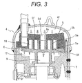
- Fig. 3 schematically shows the pressure deformation of the compression mechanism part 2 of the scroll compressor.
- the section above the fixed scroll 5 faces the discharge pressure space 4f so that the discharge pressure is applied to the upper surface of the fixed scroll 5.
- the back surface of the orbiting scroll 6 faces the back pressure chamber 17, the back pressure is applied to the back surface of the orbiting scroll 6 which is pushed upward (side of the fixed scroll 5).
- the fixed scroll 5 has the outer edge of the fixed-side plate 5b secured to the closed vessel 4, it will be deformed into the convex shape directed downward as a whole (orbiting scroll side).
- the respective wrap tooth tips fixed-side wrap tooth tip 5e, orbiting-side wrap tooth tip 6e
- the respective wrap tooth bottoms fixed-side wrap tooth bottom 5f, orbiting-side'wrap tooth bottom 6f
- Each of the fixed scroll 5 and the orbiting scroll 6 has the center part downwardly deformed into the convex shape as a whole along the deformation of the fixed scroll 5.
- the maximum displacement at the wrap center becomes further large, which makes each contact of the center between the fixed-side wrap tooth tip 5e and the orbiting-side wrap tooth bottom 6f, and between the fixed-side wrap tooth bottom 5f and the orbiting-side tooth tip 6e excessively strong.
- the tooth bottom step which becomes deeper from the outer side to the center is formed on each tooth bottom of the orbiting scroll 6 and the fixed scroll 5 (fixed-side wrap tooth bottom 5f, orbiting-side wrap tooth bottom 6f), respectively. It is assumed that the tooth bottom step becomes deeper as the distance increases between the tooth bottom (fixed-side wrap tooth bottom 5f, orbiting-side wrap booth bottom 6f) and the opposite tooth tip (fixed-side wrap tooth tip 5e, orbiting-side wrap tooth tip 6e).
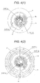
- Fig. 4 shows the orbiting scroll 6 and the fixed scroll 5 of the scroll compressor 1 as top views.
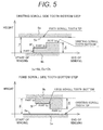
- Fig. 5 schematically represents the relationship between the wrap tooth tip and the tooth bottom seen from the direction of the wrap circumferential side.
- the step of the orbiting-side wrap tooth bottom 6f of the orbiting scroll 6 is set to change its depth from the part (c) as the reference depth at the outermost periphery to the part (b) along the inner periphery, and further to the part (a) sequentially.
- the step is formed so that the part (a) at the innermost periphery becomes the deepest, and the part (c) at the outermost periphery becomes the shallowest.
- the step of the fixed-side wrap tooth bottom 5f of the fixed scroll 5 is set to change its depth from the part (c) as the reference depth to the part (b) along the inner periphery, and further to the part (a) sequentially.
- the steps of the orbiting scroll 6 and the fixed scroll 5 are set to have each depth equally changed.
- the step is formed so that the part (a) at the innermost periphery is the deepest, and the part (c) at the outermost periphery is the shallowest.
- the above-described step on the orbiting-side wrap tooth bottom 6f is set so that the depth is changed from the part (c) as the reference at the outermost periphery to the part (b) along the inner periphery, and further to the part (a) sequentially.
- the part (a) is formed to have the depth different from the part (c) by approximately 0.02% to 0.04% of the orbiting-side wrap tooth height 6h
- the part (b) is formed to have the depth different from the part (c) by approximately 0.005% to 0.02% of the orbiting-side wrap tooth height 6h
- the part (c) is formed to have the depth of approximately 0.00% to 0.03% of the orbiting-side wrap tooth height 6h with respect to the orbiting-side mirror plate surface 6g shown in Fig. 2
- the orbiting-side wrap tooth height 6h denotes the length from the orbiting-side mirror plate surface 6g to the orbiting-side wrap tooth tip 6e of the orbiting-side wrap 6a as shown in Fig. 2 .
- the step on the fixed-side wrap tooth bottom 5f is set so that the depth is changed from the part (c) as the reference at the outermost periphery to the part (b) along the inner periphery, and further to the part (a) sequentially.
- the part (a) is formed to have the depth different from the part (c) by 0.02% to 0.04% of the fixed-side wrap tooth height 5h
- the part (b) is formed to have the depth different from the part (c) by approximately 0.005% to 0.02% of the fixed-side wrap tooth height 5h
- the part (c) is formed to have the depth different from the fixed-side wrap tooth height 5h by the amount corresponding to the fixed-side mirror plate surface 5g shown in Fig. 2 .
- the fixed-side wrap tooth height 5h in this case denotes the length from the fixed-side mirror plate surface 5g to the fixed-side wrap tooth tip 5e of the fixed-side wrap 5a.
- the structure shown in Figs. 4 and 5 serves to prevent excessive contact between the fixed-side wrap tooth bottom 5f and the orbiting-side wrap tooth tip 6e, or between the orbiting-side wrap tooth bottom 6f and the fixed-side wrap tooth tip 5e, and to ensure suppression of increase in the input by friction and improvement of reliability with respect to the wrap strength.
- the scroll compressor with the structure shown in Figs. 4 and 5 is configured that each difference in the tooth bottom steps formed on the fixed-side wrap tooth bottom 5f and the orbiting-side wrap tooth bottom 6f is equally set, resulting in unnecessary gap under the condition of maximum wrap deformation. Examinations made by the inventors have revealed the problem that under the operating condition (condition of low-speed and low-pressure ratio) of small wrap deformation, the step formed on the tooth bottom will further generate the gap, through which the refrigerant leaks between the compression chambers, resulting in the loss.
- the orbiting-side wrap tooth bottom 6f and the fixed-side wrap tooth bottom 5f are formed on the wrap-forming surface of the orbiting-side plate 6b of the orbiting scroll 6 and the wrap-forming surface of the fixed-side plate 5b of the fixed scroll 5, respectively so that each step becomes deeper from the outer periphery toward the inner periphery.
- Fig. 6 shows each depth of the orbiting-side wrap tooth bottom 6f and the fixed-side wrap tooth bottom 5f according to the embodiment.
- the step difference between the part (a) and the part (c) of the orbiting-side wrap tooth bottom 6f, and the step difference between the part (a) and the part (c) of the fixed-side wrap tooth bottom 5f are equally set by the depth ranging from 0.02% to 0.04% of the corresponding wrap tooth height.
- the step difference between the part (b) and the part (c) of the orbiting-side wrap tooth bottom 6f, and the step difference between the part (b) and the part (c) of the fixed-side wrap tooth bottom 5f are equally set by the depth ranging from 0.005% to 0.02% of the corresponding wrap tooth height.
- the step difference between the part (a) and the part (c) of the orbiting-side wrap tooth bottom 6f is made smaller than the step difference between the part (a) and the part (c) of the fixed-side wrap tooth bottom 5f.
- the step difference between the part (a) and the part (c) of the orbiting-side wrap tooth bottom 6f is formed to have the resultant depth ranging from 0.005% to 0.02% of the orbiting-side wrap tooth height 6h. Then it is made smaller than the step difference between the part (a) and the part (c) of the fixed-side wrap tooth bottom 5f (0.02% to 0.04% of the fixed-side wrap tooth height 5h).
- hs the gap between the fixed-side wrap tooth tip 5e and the orbiting-side wrap tooth bottom 6f
- hk the gap between the fixed-side wrap tooth bottom 5f and the orbiting-side wrap tooth tip 6e
- Ds the step difference between the part (a) and the part (c) of the orbiting-side wrap tooth bottom 6f
- Dk the step difference between the part (a) and the part (c) of the fixed-side wrap tooth bottom 5f
- the gap between the fixed-side wrap tooth tip 5e and the orbiting-side wrap tooth bottom 6f is defined as hs'
- the gap between the fixed-side wrap tooth bottom 5f and the orbiting-side wrap tooth tip 6e is defined as hk
- the relationship of hk > hs is established as shown in Fig. 6 .
- the step difference between the part (a) and the part (c) of the orbiting-side wrap tooth bottom 6f is defined as Ds'
- the step difference between the part (a) and the part (c) of the fixed-side wrap tooth bottom 5f is defined as Dk
- each difference in the tooth bottom steps of the orbiting scroll 6 and the fixed scroll 5 is individually set in consideration of the applied pressure and thermal deformation which may occur in the orbiting scroll and the fixed scroll.
- the inner peripheral step difference Ds' (depth) of the orbiting-side wrap tooth bottom 6f is made smaller than the inner peripheral step difference Dk (depth) of the fixed-side wrap tooth bottom 5f so as to improve sealability by eliminating the unnecessary gap, and to suppress the loss caused by leakage of the refrigerant through the gap between the wrap tooth tip and the tooth bottom.
- the scroll compressor employs the refrigerant as the work fluid especially with lower density than the R410A refrigerant, for example, an R32 refrigerant
- refrigerant is likely to leak between the adjacent compression chambers because of low density.
- the R32 refrigerant as the high-temperature refrigerant may have its temperature high during operation. It can be assumed that the gap between the wrap tooth tip and the wrap tooth bottom is widened owing to thermal expansion.
- the embodiment is configured to have the tooth bottom step that allows suppression of the loss caused by leakage of the refrigerant through the gap between the wrap tooth tip and the tooth bottom. This makes it possible to provide the high-performance scroll compressor even in the case where the single R32 refrigerant is only employed, or it is filled into the refrigeration cycle at a rate of 70% or higher.
- Fig. 7 schematically shows the structure as the view seen from the direction of the circumferential side of the wrap, representing the relationship between the wrap tooth tip and the tooth bottom.
- the second embodiment has the same structures as those of the first embodiment except the planar shape to be formed on the opposite surfaces of the wraps of the orbiting scroll 6 and the fixed scroll 5. Explanations of the components with the same functions will be omitted.
- each of the parts (b) and (a) of the orbiting-side wrap tooth bottom 6f of the scroll compressor as shown in Fig. 5 has the same depth so that the orbiting-side wrap tooth bottom 6f has two steps to eliminate the gap between the orbiting-side wrap tooth bottom 6f at the winding start side as the deepest position and the fixed-side wrap tooth tip 5e.
- the fixed-side wrap tooth bottom 5f has two steps
- the orbiting-side wrap tooth bottom 6f has the single step so that the innermost peripheral step difference Dk of the fixed-side wrap tooth bottom 5f is made deeper than the inner peripheral step difference Ds' of the orbiting-side wrap tooth bottom 6f.
- the loss may be reduced by making the depth Ds' of the inner peripheral step of the orbiting-side wrap tooth bottom 6f substantially the same as the depth (at the part (b)) at the second deepest position of the fixed-side wrap tooth bottom 5f.
- This embodiment provides the similar advantageous effects to those derived from the first embodiment.
- the embodiment is capable of reducing the manufacturing cost and time by decreasing man-hours for machining the steps decreased in comparison with the first embodiment.
- This embodiment is configured that the stepped portion from the part (b) to the part (c) is made perpendicular to the fixed-side wrap tooth tip 5e as shown in Fig. 7 .
- it is possible to form the slope which inclines from the part (b) to the part (c) so as to change the depth smoothly. This makes it possible to reduce leakage of the refrigerant through the gap generated at the part (c) of the step.
- the circumferential step of the orbiting-side wrap tooth bottom 6f may be easily subjected to high-precision machining with the end mill.
- the aforementioned structure of this embodiment is applicable to any of the embodiments.
- Fig. 8 schematically shows the structure as the view seen from the direction of the circumferential side of the wrap, representing the relationship between the wrap tooth tip and the tooth bottom.
- This embodiment has the same structures as those of the first embodiment except the planar shape to be formed on the opposite surfaces of the wraps of the orbiting scroll 6 and the fixed scroll 5. Explanations of the components with the same functions will be omitted.
- Ds 1/2Dk.
- the depth Ds' as the step difference at the innermost periphery of the orbiting-side wrap tooth bottom 6f is approximately half the depth of the step difference Dk as the deepest part of the fixed-side wrap tooth bottom 5f.
- This embodiment also provides substantially the same advantageous effects as those of the first or the second embodiment.
- the depth of the tooth bottom at the orbiting scroll side is set to be half the depth of the tooth bottom at the fixed scroll side, the cutting amount through machining may be reduced, thus decreasing the machining time and prolonging life of the tool.
- This embodiment has the same structures as those of the first to the third embodiments except the use of the ferrite magnet electric motor formed by embedding the ferrite magnet in the rotor of the electric motor 3 of the scroll compressor. Explanations of the components with the same functions will be omitted.
- the compressor that employs the ferrite magnet motor is expected to greatly reduce the cost.
- the use of the ferrite magnet motor has the problem of lower efficiency especially in the low-speed region compared with the neodymium magnet motor.
- Application of the first to the fourth embodiments allows the step size (depth) of the tooth bottom 6f of the orbiting scroll 6 to be smaller than the step size (depth) of the tooth bottom 5f of the fixed scroll 5. This makes it possible to improve sealability, and reduce the loss caused by leakage of the refrigerant through the gap between the wrap tooth tip and the tooth bottom, providing the highly efficient scroll compressor at a low cost even in the low-speed region.
- This embodiment has the same structures as those of the first to the fourth embodiments except employment of only the single R32 refrigerant in the scroll compressor. Explanations of the components with the same functions will be omitted.
- the global warming potential (GWP) of the R32 refrigerant is 675 which is approximately one third of the R410A, thus delivering less burden on the environment. Compared with the refrigerant such as the R410A, it exhibits lower density, and is likely to leak from the sealed space. Furthermore, the use of the R32 refrigerant may increase the operation temperature, which tends to deform the wrap under the thermal influence, thus widening the gap between the tooth tip and the tooth bottom.
- the single R32 refrigerant is only employed or filled into the refrigeration cycle at a rate of approximately 70% or higher through application of the first to the fourth embodiments. Then the step size (depth) of the tooth bottom 6f of the orbiting scroll 6 is made smaller than the step size (depth) of the tooth bottom 5f of the fixed scroll 5 so as to improve sealability by eliminating the unnecessary gap, and to reduce the loss caused by leakage of the refrigerant from the gap between the wrap tooth tip and the tooth bottom. This makes it possible to provide the highly efficient scroll compressor while using the refrigerant with a small environmental load.
Landscapes
- Engineering & Computer Science (AREA)
- Mechanical Engineering (AREA)
- General Engineering & Computer Science (AREA)
- Rotary Pumps (AREA)
Abstract
Description
- The present invention relates to a scroll compressor.
- Japanese Patent No.
2009-281509 - PTL 1:
JP-A-2009-281209 -
Patent Literature 1 discloses that the tooth bottoms are preliminarily formed on opposite surfaces of mirror plates of the orbiting scroll and the fixed scroll, each step of which has the depth increased from the outer peripheral side to the inner peripheral side in expectation of the scroll deformation, reducing the friction loss caused by the contact between the wrap tooth tip and the opposing tooth bottom. The thus formed tooth bottom step may suppress the contact between the wrap tooth tip and the tooth bottom. If the tooth bottom step is unnecessarily widened, the gap is generated, through which gas leaks to the inside of the compression chamber, thus increasing the loss. - It is an object of the present invention to suppress the contact between the wrap tooth tip and the tooth bottom by forming the tooth bottom step, and to reduce the loss caused by the gap generated as a result of enlarging the tooth bottom step.
- The aforementioned problem may be solved by employing the structures as described in the claims.
- The present invention includes a plurality of means for solving the problem, one of which will be described as an example below.
- The present invention provides a scroll compressor which includes a fixed scroll including a fixed-side plate and a fixed-side wrap standing on one surface of the fixed-side plate while retaining a spiral shape, an orbiting scroll including an orbiting-side plate, and an orbiting-side wrap standing on one surface of the orbiting-side plate while retaining a spiral shape, which allows the orbiting-side wrap to be in mesh with the fixed-side wrap for orbiting with respect to the fixed scroll to form a compression chamber, and an electric motor for driving the orbiting scroll via a crankshaft. Each tooth bottom of the fixed-side wrap and the orbiting-side wrap has a step formed to become deeper from an outer periphery to an inner periphery. The step is formed on the tooth bottom of the fixed-side wrap at the inner periphery so as to be deeper than the step formed on the tooth bottom of the orbiting-side wrap at the inner periphery.
- The present invention is capable of suppressing the contact between the wrap tooth tip and the tooth bottom by forming the tooth bottom step, and reducing the loss caused by the gap generated as a result of enlarging the tooth bottom step. Problems, structures and effects other than those described above will be specifically explained in the following embodiments.
-
-
Fig. 1 is a longitudinal sectional view of a first embodiment of a scroll compressor. -
Fig. 2 is a view showing structures of the fixed scroll and the orbiting scroll. -
Fig. 3 is a schematic view representing pressure deformation of the rear part of the scroll compressor according to the first embodiment. -
Fig. 4(1) is a top view of the tooth bottom of the orbiting scroll according to the first embodiment. -
Fig. 4(2) is a top view of the tooth bottom of the fixed scroll according to the first embodiment. -
Fig. 5 is an explanatory view showing each wrap structure of the orbiting scroll and the fixed scroll. -
Fig. 6 is a view showing the first embodiment corresponding toFig. 5 . -
Fig. 7 is a view showing a second embodiment corresponding toFig. 5 . -
Fig. 8 is a view showing a third embodiment corresponding toFig. 6 . - Embodiments of the present invention will be described referring to the drawings.
- An embodiment of the scroll compressor will be described, which is configured to optimize the gap between wraps so as to suppress the load exerted to the wrap and to reduce the loss caused by leakage into the compression chamber.
-
Fig. 1 shows an example of the structure of the scroll compressor according to the embodiment. - A
scroll compressor 1 includes acompression mechanism part 2, anelectric motor 3 for driving thecompression mechanism part 2, and a closedvessel 4 for storing thecompression mechanism part 2 and theelectric motor 3. The embodiment is formed as a vertical scroll compressor configured to have thecompression mechanism part 2 disposed at the upper section in the closedvessel 2, theelectric motor 3 disposed in the intermediate section, and anoil sump 15 disposed at the lower section of the closedvessel 4. The closedvessel 4 is formed by welding alid cap 4b and abottom cap 4c to top and bottom parts of acylindrical chamber 4a. Anintake pipe 4d is mounted to thelid cap 4b, and adischarge pipe 4e is mounted to the side surface of thecylindrical chamber 4a. The closedvessel 4 hasdischarge pressure space 4f working as the discharge pressure therein. Thecompression mechanism part 2 and theelectric motor 3 are stored in thedischarge pressure space 4f. Thecompression mechanism part 2 includes afixed scroll 5, anorbiting scroll 6, and aframe 7 as basic components. Thefixed scroll 5 and theframe 7 are secured with a bolt, and theorbiting scroll 6 is supported with theframe 7. -
Fig. 2 shows cross-sections of basic structures of thefixed scroll 5 and theorbiting scroll 6 of thescroll compressor 1 according to the embodiment. Referring toFig. 2 , consistency does not necessarily exist in the relative dimension ratio between thefixed scroll 5 and theorbiting scroll 6. Thefixed scroll 5 includes a disc-like top plate (fixed-side plate 5b), a spiral fixed-side wrap 5a which stands on the inner periphery at the lower section of the fixed-side plate 5b, a cylindrical fixed-side mirror plate 5g disposed on the outer periphery of the fixed-side plate 5b to surround thewrap 5a, and anintake port 5c and adischarge port 5d which are provided at the upper section of the fixed-side plate 5b. The fixed scroll as described above is secured to theframe 7 with the bolt. - The orbiting
scroll 6 includes a disc-like orbiting-side plate 6b, and a spiral orbiting-side wrap 6a, standing on the inner periphery of the orbiting-side plate 6b at the side where the fixed-side wrap 5a of thefixed scroll 5 stands. The orbitingscroll 6 is orbitally arranged so as to allow the wrap to be in mesh with the wrap of thefixed scroll 5 to formcompression chambers 16. Aneccentric pin 9b of acrankshaft 9 is connected to a back surface side of the orbiting scroll 6 (the lower side as shown inFigs. 1 and2 ). The orbiting motion of the orbiting scroll 6 with respect to thefixed scroll 5 ensures compression to reduce the volume thereof. - Each scroll wrap (fixed-
side wrap 5a, orbiting-side wrap 6a) is formed of an involute curve of the circle as the basic curve, and has an asymmetrical scroll shape, having a compression chamber at the outer line side formed outside the wrap at a winding end side of theorbiting scroll 6 and a compression chamber at the inner line side formed inside the wrap each having the different size in the state where both scrolls are meshed with each other, and each phase is shifted at approximately 180° with respect to rotation of the shaft. The outer periphery of theframe 7 is secured to an inner wall surface of the closedvessel 4 through welding, and provided with amain bearing 8 which supports thecrankshaft 9 rotatably. - An Oldham
ring 10 is disposed between the back surface side of theorbiting scroll 6 and theframe 7. The Oldhamring 10 is fitted in the grooves formed in the back surface side of theorbiting scroll 6 and in theframe 7 so that the orbiting scroll 6 revolves in association with eccentric rotation of theeccentric pin 9b of thecrankshaft 9 while being kept from rotating. - The
electric motor 3 includes astator 3a and arotor 3b. Thestator 3a is secured to the closedvessel 4 through press fitting, shrink fitting and the like. Therotor 3b is rotatably disposed at the inner side of thestator 3a. Therotor 3b is secured to thecrankshaft 9, through which theorbiting scroll 6 is orbitally operated by rotation of therotor 3b. - The
crankshaft 9 includes amain shaft 9a and aneccentric pin 9b, which is supported with a main bearing 8 and a sub bearing 11. Theeccentric pin 9b is integrally formed with thecrankshaft 9a with eccentricity therebetween, and is inserted into an orbiting bearing 6d formed on the back surface of the orbitingscroll 6. Thecrankshaft 9 is driven by theelectric motor 3, and theeccentric pin 9b eccentrically rotates with respect to themain shaft 9a so that theorbiting scroll 6 is driven. Thecrankshaft 9 includes anoil passage 9c formed therein for guiding the lubricant to themain bearing 8, thesub bearing 11 and theorbiting bearing 6d. Apump 14 is disposed at the lower end of theoil sump 15 for drawing the lubricant so as to be guided into theoil passage 9c. Thesub bearing 11 is secured to theclosed vessel 4 via ahousing 12 and alower frame 13. Thesub bearing 11 rotatably retains one end of themain shaft 9a of the crankshaft at the side of the oil sump using a slide bearing, a roll bearing, a spherical bearing member and the like. - As the
orbiting scroll 6 is orbitally operated via thecrankshaft 9 driven by theelectric motor 3, wraps of both theorbiting scroll 6 and the fixedscroll 5 are meshed with each other so that two differently sized compression chambers (compression chamber at inner line side, compression chamber at outer line side) are generated alternately with phase difference at 180°. The work fluid such as refrigerant gas is introduced from theintake pipe 4d into thecompression chambers 16 defined by theorbiting scroll 6 and the fixedscroll 5. The refrigerant gas has its volume reduced toward the center of the scroll for compression. The compressed refrigerant gas is discharged from thedischarge port 5d formed in the upper center of the fixed-side plate 5b of the fixedscroll 5 into thedischarge pressure space 4f in theclosed vessel 4. The gas then circulates around thecompression mechanism part 2 and theelectric motor 3, and flows to the outside from thedischarge pipe 4e. The space within theclosed vessel 4 serves as so called high pressure chamber compressor where the discharge pressure is held. - The oil path for the lubricant will be described. A
back pressure chamber 17 is formed between the back surface side of theorbiting scroll 6 and theframe 7, where the pressure is kept to the intermediate level between the pressure inside theintake pipe 4d and the pressure in thedischarge pressure space 4f. Theback pressure chamber 17 is disposed on the path through which the lubricant is fed to the sliding part of thecompression mechanism part 2 after passing through theoil passage 9c from theoil sump 15 for lubricating theorbiting bearing 6d. Theflat plate 6b of theorbiting scroll 6 has aback pressure hole 6c for intermittently communicating thecompression chamber 16 and theback pressure chamber 17 formed on the back surface of the orbiting scroll so that the pressure in theback pressure chamber 17 is kept to the intermediate level (hereinafter referred to as the back pressure) between the intake pressure and the discharge pressure. The resultant force of the back pressure and the discharge pressure applied to the space at the center on the inner peripheral side of aseal member 18 allows theorbiting scroll 6 to be pressed against the fixedscroll 5 from the back surface. - Then pressure deformation of the
compression mechanism part 2, which occurs upon operation of the compressor, will be described. -
Fig. 3 schematically shows the pressure deformation of thecompression mechanism part 2 of the scroll compressor. As the drawing shows, the section above the fixedscroll 5 faces thedischarge pressure space 4f so that the discharge pressure is applied to the upper surface of the fixedscroll 5. As the back surface of theorbiting scroll 6 faces theback pressure chamber 17, the back pressure is applied to the back surface of theorbiting scroll 6 which is pushed upward (side of the fixed scroll 5). - As the scroll compressor shown in
Fig. 3 is configured that the fixedscroll 5 has the outer edge of the fixed-side plate 5b secured to theclosed vessel 4, it will be deformed into the convex shape directed downward as a whole (orbiting scroll side). As theorbiting scroll 6 is pushed against the fixedscroll 5 downwardly deformed into the convex shape, the respective wrap tooth tips (fixed-sidewrap tooth tip 5e, orbiting-sidewrap tooth tip 6e) at the center of both scrolls are brought into contact with the respective wrap tooth bottoms (fixed-sidewrap tooth bottom 5f, orbiting-side'wrap tooth bottom 6f) one another. Each of the fixedscroll 5 and theorbiting scroll 6 has the center part downwardly deformed into the convex shape as a whole along the deformation of the fixedscroll 5. Especially in the high-pressure ratio condition, the maximum displacement at the wrap center becomes further large, which makes each contact of the center between the fixed-sidewrap tooth tip 5e and the orbiting-sidewrap tooth bottom 6f, and between the fixed-sidewrap tooth bottom 5f and the orbiting-side tooth tip 6e excessively strong. In order to suppress the friction loss and wrap breakage owing to the excessive contact, the tooth bottom step which becomes deeper from the outer side to the center is formed on each tooth bottom of theorbiting scroll 6 and the fixed scroll 5 (fixed-sidewrap tooth bottom 5f, orbiting-sidewrap tooth bottom 6f), respectively. It is assumed that the tooth bottom step becomes deeper as the distance increases between the tooth bottom (fixed-sidewrap tooth bottom 5f, orbiting-side wrap booth bottom 6f) and the opposite tooth tip (fixed-sidewrap tooth tip 5e, orbiting-sidewrap tooth tip 6e). - Features of structures of the steps on the respective wrap tooth bottoms (fixed-side
wrap tooth bottom 5f, orbiting-sidewrap tooth bottom 6f) will be described. -
Fig. 4 shows theorbiting scroll 6 and the fixedscroll 5 of thescroll compressor 1 as top views.Fig. 5 schematically represents the relationship between the wrap tooth tip and the tooth bottom seen from the direction of the wrap circumferential side. Referring toFig. 4(1) , the step of the orbiting-sidewrap tooth bottom 6f of theorbiting scroll 6 is set to change its depth from the part (c) as the reference depth at the outermost periphery to the part (b) along the inner periphery, and further to the part (a) sequentially. In other words, the step is formed so that the part (a) at the innermost periphery becomes the deepest, and the part (c) at the outermost periphery becomes the shallowest. - Referring to
Fig. 4(2) , like the orbiting-sidewrap tooth bottom 6f shown inFig. 4(1) , the step of the fixed-sidewrap tooth bottom 5f of the fixedscroll 5 is set to change its depth from the part (c) as the reference depth to the part (b) along the inner periphery, and further to the part (a) sequentially. The steps of theorbiting scroll 6 and the fixedscroll 5 are set to have each depth equally changed. In other words, the step is formed so that the part (a) at the innermost periphery is the deepest, and the part (c) at the outermost periphery is the shallowest. - Referring to
Fig. 5 , the above-described step on the orbiting-sidewrap tooth bottom 6f is set so that the depth is changed from the part (c) as the reference at the outermost periphery to the part (b) along the inner periphery, and further to the part (a) sequentially. Specifically, the part (a) is formed to have the depth different from the part (c) by approximately 0.02% to 0.04% of the orbiting-sidewrap tooth height 6h, the part (b) is formed to have the depth different from the part (c) by approximately 0.005% to 0.02% of the orbiting-sidewrap tooth height 6h, and the part (c) is formed to have the depth of approximately 0.00% to 0.03% of the orbiting-sidewrap tooth height 6h with respect to the orbiting-sidemirror plate surface 6g shown inFig. 2 . The orbiting-sidewrap tooth height 6h denotes the length from the orbiting-sidemirror plate surface 6g to the orbiting-sidewrap tooth tip 6e of the orbiting-side wrap 6a as shown inFig. 2 . - Meanwhile, the step on the fixed-side
wrap tooth bottom 5f is set so that the depth is changed from the part (c) as the reference at the outermost periphery to the part (b) along the inner periphery, and further to the part (a) sequentially. Like the case as described above, the part (a) is formed to have the depth different from the part (c) by 0.02% to 0.04% of the fixed-sidewrap tooth height 5h, the part (b) is formed to have the depth different from the part (c) by approximately 0.005% to 0.02% of the fixed-sidewrap tooth height 5h, and the part (c) is formed to have the depth different from the fixed-sidewrap tooth height 5h by the amount corresponding to the fixed-sidemirror plate surface 5g shown inFig. 2 . The fixed-sidewrap tooth height 5h in this case denotes the length from the fixed-sidemirror plate surface 5g to the fixed-sidewrap tooth tip 5e of the fixed-side wrap 5a. - Upon application of pressure and heat of the work fluid to the
compression mechanism part 2 through the drivenscroll compressor 1, the structure shown inFigs. 4 and5 serves to prevent excessive contact between the fixed-sidewrap tooth bottom 5f and the orbiting-sidewrap tooth tip 6e, or between the orbiting-sidewrap tooth bottom 6f and the fixed-sidewrap tooth tip 5e, and to ensure suppression of increase in the input by friction and improvement of reliability with respect to the wrap strength. - The scroll compressor with the structure shown in
Figs. 4 and5 is configured that each difference in the tooth bottom steps formed on the fixed-sidewrap tooth bottom 5f and the orbiting-sidewrap tooth bottom 6f is equally set, resulting in unnecessary gap under the condition of maximum wrap deformation. Examinations made by the inventors have revealed the problem that under the operating condition (condition of low-speed and low-pressure ratio) of small wrap deformation, the step formed on the tooth bottom will further generate the gap, through which the refrigerant leaks between the compression chambers, resulting in the loss. - Features of the scroll compressor will be described referring to
Figs. 4 and6 hereinafter as an embodiment for preventing increase in the loss caused by leakage of the refrigerant through the gap between the wrap tooth tip and the wrap tooth bottom. - As
Fig. 4 shows, the orbiting-sidewrap tooth bottom 6f and the fixed-sidewrap tooth bottom 5f are formed on the wrap-forming surface of the orbiting-side plate 6b of theorbiting scroll 6 and the wrap-forming surface of the fixed-side plate 5b of the fixedscroll 5, respectively so that each step becomes deeper from the outer periphery toward the inner periphery. -
Fig. 6 shows each depth of the orbiting-sidewrap tooth bottom 6f and the fixed-sidewrap tooth bottom 5f according to the embodiment. As for the structure described referring toFig. 5 , the step difference between the part (a) and the part (c) of the orbiting-sidewrap tooth bottom 6f, and the step difference between the part (a) and the part (c) of the fixed-sidewrap tooth bottom 5f are equally set by the depth ranging from 0.02% to 0.04% of the corresponding wrap tooth height. The step difference between the part (b) and the part (c) of the orbiting-sidewrap tooth bottom 6f, and the step difference between the part (b) and the part (c) of the fixed-sidewrap tooth bottom 5f are equally set by the depth ranging from 0.005% to 0.02% of the corresponding wrap tooth height. - Meanwhile, as for the structure according to the embodiment shown in
Fig. 6 , the step difference between the part (a) and the part (c) of the orbiting-sidewrap tooth bottom 6f is made smaller than the step difference between the part (a) and the part (c) of the fixed-sidewrap tooth bottom 5f. Specifically, the step difference between the part (a) and the part (c) of the orbiting-sidewrap tooth bottom 6f is formed to have the resultant depth ranging from 0.005% to 0.02% of the orbiting-sidewrap tooth height 6h. Then it is made smaller than the step difference between the part (a) and the part (c) of the fixed-sidewrap tooth bottom 5f (0.02% to 0.04% of the fixed-sidewrap tooth height 5h). - Assuming that the gap between the fixed-side
wrap tooth tip 5e and the orbiting-sidewrap tooth bottom 6f is referred to as hs, and the gap between the fixed-sidewrap tooth bottom 5f and the orbiting-sidewrap tooth tip 6e is referred to as hk, the relationship of hs = hk is established as shown inFig. 5 . Assuming that the step difference between the part (a) and the part (c) of the orbiting-sidewrap tooth bottom 6f is referred to as Ds, and the step difference between the part (a) and the part (c) of the fixed-sidewrap tooth bottom 5f is referred to as Dk, the relationship of Ds = Dk is established as shown inFig. 5 . - Meanwhile, referring to
Fig. 6 , assuming that the gap between the fixed-sidewrap tooth tip 5e and the orbiting-sidewrap tooth bottom 6f is defined as hs', and the gap between the fixed-sidewrap tooth bottom 5f and the orbiting-sidewrap tooth tip 6e is defined as hk, the relationship of hk > hs is established as shown inFig. 6 . Assuming that the step difference between the part (a) and the part (c) of the orbiting-sidewrap tooth bottom 6f is defined as Ds', and the step difference between the part (a) and the part (c) of the fixed-sidewrap tooth bottom 5f is defined as Dk, the relationship of Dk > Ds' is established. - Each difference in the tooth bottom steps of the
orbiting scroll 6 and the fixedscroll 5 is individually set in consideration of the applied pressure and thermal deformation which may occur in the orbiting scroll and the fixed scroll. As a result, the inner peripheral step difference Ds' (depth) of the orbiting-sidewrap tooth bottom 6f is made smaller than the inner peripheral step difference Dk (depth) of the fixed-sidewrap tooth bottom 5f so as to improve sealability by eliminating the unnecessary gap, and to suppress the loss caused by leakage of the refrigerant through the gap between the wrap tooth tip and the tooth bottom. - In the case where the scroll compressor employs the refrigerant as the work fluid especially with lower density than the R410A refrigerant, for example, an R32 refrigerant, it can be assumed that such refrigerant is likely to leak between the adjacent compression chambers because of low density. The R32 refrigerant as the high-temperature refrigerant may have its temperature high during operation. It can be assumed that the gap between the wrap tooth tip and the wrap tooth bottom is widened owing to thermal expansion. The embodiment is configured to have the tooth bottom step that allows suppression of the loss caused by leakage of the refrigerant through the gap between the wrap tooth tip and the tooth bottom. This makes it possible to provide the high-performance scroll compressor even in the case where the single R32 refrigerant is only employed, or it is filled into the refrigeration cycle at a rate of 70% or higher.
- A second embodiment of the scroll compressor according to the present invention will be described.
-
Fig. 7 schematically shows the structure as the view seen from the direction of the circumferential side of the wrap, representing the relationship between the wrap tooth tip and the tooth bottom. The second embodiment has the same structures as those of the first embodiment except the planar shape to be formed on the opposite surfaces of the wraps of theorbiting scroll 6 and the fixedscroll 5. Explanations of the components with the same functions will be omitted. - Referring to
Fig. 7 , in this embodiment, each of the parts (b) and (a) of the orbiting-sidewrap tooth bottom 6f of the scroll compressor as shown inFig. 5 has the same depth so that the orbiting-sidewrap tooth bottom 6f has two steps to eliminate the gap between the orbiting-sidewrap tooth bottom 6f at the winding start side as the deepest position and the fixed-sidewrap tooth tip 5e. In other words, the fixed-sidewrap tooth bottom 5f has two steps, and the orbiting-sidewrap tooth bottom 6f has the single step so that the innermost peripheral step difference Dk of the fixed-sidewrap tooth bottom 5f is made deeper than the inner peripheral step difference Ds' of the orbiting-sidewrap tooth bottom 6f. It has been confirmed that the loss may be reduced by making the depth Ds' of the inner peripheral step of the orbiting-sidewrap tooth bottom 6f substantially the same as the depth (at the part (b)) at the second deepest position of the fixed-sidewrap tooth bottom 5f. - This embodiment provides the similar advantageous effects to those derived from the first embodiment. The embodiment is capable of reducing the manufacturing cost and time by decreasing man-hours for machining the steps decreased in comparison with the first embodiment. This embodiment is configured that the stepped portion from the part (b) to the part (c) is made perpendicular to the fixed-side
wrap tooth tip 5e as shown inFig. 7 . Besides the configuration as described above, it is possible to form the slope which inclines from the part (b) to the part (c) so as to change the depth smoothly. This makes it possible to reduce leakage of the refrigerant through the gap generated at the part (c) of the step. The circumferential step of the orbiting-sidewrap tooth bottom 6f may be easily subjected to high-precision machining with the end mill. The aforementioned structure of this embodiment is applicable to any of the embodiments. - A third embodiment of the scroll compressor according to the present invention will be described.
-
Fig. 8 schematically shows the structure as the view seen from the direction of the circumferential side of the wrap, representing the relationship between the wrap tooth tip and the tooth bottom. This embodiment has the same structures as those of the first embodiment except the planar shape to be formed on the opposite surfaces of the wraps of theorbiting scroll 6 and the fixedscroll 5. Explanations of the components with the same functions will be omitted. - Referring to
Fig. 8 , in this embodiment, the orbiting-sidewrap tooth bottom 6f has two steps in the second embodiment shown inFig. 7 so that the relationship of the depth at the part (a) of the shallow orbiting-sidewrap tooth bottom 6f with the depth at the part (a) of the fixed-sidewrap tooth bottom 5f is expressed by Ds = 1/2Dk. In other words, asFig. 8 shows, the depth Ds' as the step difference at the innermost periphery of the orbiting-sidewrap tooth bottom 6f is approximately half the depth of the step difference Dk as the deepest part of the fixed-sidewrap tooth bottom 5f. - It has been confirmed that the aforementioned structure prevents contact with the wrap tooth tip, and reduces the loss. This embodiment also provides substantially the same advantageous effects as those of the first or the second embodiment. As the depth of the tooth bottom at the orbiting scroll side is set to be half the depth of the tooth bottom at the fixed scroll side, the cutting amount through machining may be reduced, thus decreasing the machining time and prolonging life of the tool.
- A fourth embodiment of the scroll compressor according to the present invention will be described.
- This embodiment has the same structures as those of the first to the third embodiments except the use of the ferrite magnet electric motor formed by embedding the ferrite magnet in the rotor of the
electric motor 3 of the scroll compressor. Explanations of the components with the same functions will be omitted. - As the ferrite magnet motor is less expensive than the neodymium magnet motor, the compressor that employs the ferrite magnet motor is expected to greatly reduce the cost. However, the use of the ferrite magnet motor has the problem of lower efficiency especially in the low-speed region compared with the neodymium magnet motor. Application of the first to the fourth embodiments allows the step size (depth) of the
tooth bottom 6f of theorbiting scroll 6 to be smaller than the step size (depth) of thetooth bottom 5f of the fixedscroll 5. This makes it possible to improve sealability, and reduce the loss caused by leakage of the refrigerant through the gap between the wrap tooth tip and the tooth bottom, providing the highly efficient scroll compressor at a low cost even in the low-speed region. - A sixth embodiment of the scroll compressor according to the present invention will be described.
- This embodiment has the same structures as those of the first to the fourth embodiments except employment of only the single R32 refrigerant in the scroll compressor. Explanations of the components with the same functions will be omitted.
- The global warming potential (GWP) of the R32 refrigerant is 675 which is approximately one third of the R410A, thus delivering less burden on the environment. Compared with the refrigerant such as the R410A, it exhibits lower density, and is likely to leak from the sealed space. Furthermore, the use of the R32 refrigerant may increase the operation temperature, which tends to deform the wrap under the thermal influence, thus widening the gap between the tooth tip and the tooth bottom.
- The single R32 refrigerant is only employed or filled into the refrigeration cycle at a rate of approximately 70% or higher through application of the first to the fourth embodiments. Then the step size (depth) of the
tooth bottom 6f of theorbiting scroll 6 is made smaller than the step size (depth) of thetooth bottom 5f of the fixedscroll 5 so as to improve sealability by eliminating the unnecessary gap, and to reduce the loss caused by leakage of the refrigerant from the gap between the wrap tooth tip and the tooth bottom. This makes it possible to provide the highly efficient scroll compressor while using the refrigerant with a small environmental load. -
- 1:
- scroll compressor
- 2:
- compression mechanism part
- 3:
- electric motor (3a: rotor, 3b: stator)
- 4:
- closed vessel (4a: cylindrical chamber, 4b: lid cap,
- 4c:
- bottom cap, 4d: intake pipe, 4e: discharge pipe, 4f: discharge space)
- 5:
- fixed scroll (5a: fixed-side wrap, 5b: fixed-side plate,
- 5c:
- intake port, 5d: discharge port, 5e: fixed-side wrap tooth tip, 5f: fixed-side wrap tooth bottom, 5g: fixed-side mirror plate surface, 5h: fixed-side wrap tooth height)
- 6:
- orbiting scroll (6a: orbiting-side wrap, 6b: orbiting-side plate, 6c: back pressure hole, 6d: orbiting bearing,
- 6e:
- orbiting-side wrap tooth tip, 6f: orbiting-side wrap tooth bottom, 6g: orbiting-side mirror plate surface, 6h: orbiting-side wrap tooth height)
- 7:
- frame
- 8:
- main bearing
- 9:
- crankshaft (9a: main shaft, 9b: eccentric pin, 9c: oil passage)
- 10:
- Oldham ring
- 11:
- sub bearing
- 12:
- housing
- 13:
- lower frame
- 14:
- pump
- 15:
- oil sump
- 16:
- compression chamber
- 17:
- back pressure chamber
Claims (7)
- A scroll compressor comprising:a fixed scroll including a fixed-side plate and a fixed-side wrap standing on one surface of the fixed-side plate while retaining a spiral shape;an orbiting scroll including an orbiting-side plate, and an orbiting-side wrap standing on one surface of the orbiting-side plate while retaining a spiral shape, which allows the orbiting-side wrap to be in mesh with the fixed-side wrap for orbiting with respect to the fixed scroll to form a compression chamber; andan electric motor for driving the orbiting scroll via a crankshaft,wherein each tooth bottom of the fixed-side wrap and the orbiting-side wrap has a step formed to become deeper from an outer periphery to an inner periphery; andthe step is formed on the tooth bottom of the fixed-side wrap at the inner periphery so as to be deeper than the step formed on the tooth bottom of the orbiting-side wrap at the inner periphery.
- The scroll compressor according to claim 1,
wherein two steps are formed on the tooth bottom of the fixed-side wrap;
one step is formed on the tooth bottom of the orbiting-side wrap; and
the fixed-side wrap has the step formed on the tooth bottom at the innermost periphery deeper than the step formed on the tooth bottom of the orbiting-side wrap at the inner periphery. - The scroll compressor according to claim 2, wherein the step formed on the tooth bottom of the orbiting-side wrap at the inner periphery has substantially the same depth as the depth of the second deepest step formed on the tooth bottom of the fixed-side wrap.
- The scroll compressor according to claim 1, wherein the step formed on the tooth bottom of the orbiting-side wrap at the innermost periphery has the depth substantially half the depth of the deepest step formed on the tooth bottom of the fixed-side wrap.
- The scroll compressor according to claim 1, wherein the step formed on the tooth bottom of the orbiting-side wrap at the innermost periphery has the depth ranging from 0.005% to 0.02% of an orbiting-side wrap tooth height 6h.
- The scroll compressor according to any one of claims 1 to 5, wherein the electric motor including a stator and a rotor is configured as a ferrite magnet electric motor having a ferrite magnet embedded in the rotor.
- The scroll compressor according to any one of claims 1 to 5, wherein an R32 refrigerant is only filled into a refrigeration cycle, or filled into the refrigeration cycle at a rate of approximately 70% or higher.
Applications Claiming Priority (1)
| Application Number | Priority Date | Filing Date | Title |
|---|---|---|---|
| PCT/JP2013/059444 WO2014155646A1 (en) | 2013-03-29 | 2013-03-29 | Scroll compressor |
Publications (2)
| Publication Number | Publication Date |
|---|---|
| EP2980408A1 true EP2980408A1 (en) | 2016-02-03 |
| EP2980408A4 EP2980408A4 (en) | 2016-12-21 |
Family
ID=51622711
Family Applications (1)
| Application Number | Title | Priority Date | Filing Date |
|---|---|---|---|
| EP13880382.0A Withdrawn EP2980408A4 (en) | 2013-03-29 | 2013-03-29 | SPIRAL COMPRESSOR |
Country Status (5)
| Country | Link |
|---|---|
| US (1) | US20160003247A1 (en) |
| EP (1) | EP2980408A4 (en) |
| JP (1) | JP6081577B2 (en) |
| CN (1) | CN105074218B (en) |
| WO (1) | WO2014155646A1 (en) |
Cited By (1)
| Publication number | Priority date | Publication date | Assignee | Title |
|---|---|---|---|---|
| EP3483447A4 (en) * | 2016-07-06 | 2020-01-15 | Daikin Industries, Ltd. | Scroll compressor |
Families Citing this family (7)
| Publication number | Priority date | Publication date | Assignee | Title |
|---|---|---|---|---|
| JP6200819B2 (en) * | 2014-01-22 | 2017-09-20 | ジョンソンコントロールズ ヒタチ エア コンディショニング テクノロジー(ホンコン)リミテッド | Scroll compressor |
| JP6226002B2 (en) | 2016-01-26 | 2017-11-08 | ダイキン工業株式会社 | Scroll compressor and air conditioner equipped with the same |
| US11015600B2 (en) * | 2016-02-10 | 2021-05-25 | Mitsubishi Electric Corporation | Scroll compressor having sub-discharge port with involute-shaped opening |
| JP2018003762A (en) * | 2016-07-06 | 2018-01-11 | ダイキン工業株式会社 | Scroll compressor |
| CN108425845B (en) * | 2018-05-16 | 2024-07-09 | 上海加冷松芝汽车空调股份有限公司 | A scroll compressor |
| EP4047208B1 (en) * | 2019-10-15 | 2026-01-28 | Mitsubishi Electric Corporation | Scroll compressor |
| JP7304432B2 (en) * | 2019-12-24 | 2023-07-06 | 日立ジョンソンコントロールズ空調株式会社 | Scroll compressor and refrigeration cycle device using the scroll compressor |
Family Cites Families (15)
| Publication number | Priority date | Publication date | Assignee | Title |
|---|---|---|---|---|
| JPS6365187A (en) * | 1986-09-05 | 1988-03-23 | Hitachi Ltd | Hermetic scroll compressor |
| JPH01159482A (en) * | 1987-12-16 | 1989-06-22 | Hitachi Ltd | scroll compressor |
| JPH0539785A (en) * | 1991-08-02 | 1993-02-19 | Hitachi Ltd | Scroll compressor |
| JPH06317269A (en) * | 1993-05-10 | 1994-11-15 | Hitachi Ltd | Hermetic scroll compressor |
| JPH0719187A (en) * | 1993-07-01 | 1995-01-20 | Hitachi Ltd | Scroll fluid machinery |
| JP2956509B2 (en) * | 1995-01-17 | 1999-10-04 | 松下電器産業株式会社 | Scroll gas compressor |
| US5741120A (en) * | 1995-06-07 | 1998-04-21 | Copeland Corporation | Capacity modulated scroll machine |
| JP3555549B2 (en) * | 2000-03-31 | 2004-08-18 | ダイキン工業株式会社 | High pressure dome type compressor |
| JP4505196B2 (en) * | 2003-06-17 | 2010-07-21 | パナソニック株式会社 | Scroll compressor |
| WO2005001292A1 (en) * | 2003-06-17 | 2005-01-06 | Matsushita Electric Industrial Co., Ltd. | Scroll compressor |
| JP5030581B2 (en) * | 2006-12-28 | 2012-09-19 | 三菱重工業株式会社 | Scroll compressor |
| JP2009281209A (en) | 2008-05-20 | 2009-12-03 | Hitachi Appliances Inc | Scroll compressor |
| JP2009281509A (en) | 2008-05-22 | 2009-12-03 | Mitsubishi Electric Corp | Automatic transmission |
| JP4775494B2 (en) * | 2010-02-15 | 2011-09-21 | ダイキン工業株式会社 | Scroll compressor |
| US9671119B2 (en) * | 2011-01-31 | 2017-06-06 | Mitsubishi Electric Corporation | Air-conditioning apparatus |
-
2013
- 2013-03-29 JP JP2015507853A patent/JP6081577B2/en active Active
- 2013-03-29 CN CN201380073432.9A patent/CN105074218B/en active Active
- 2013-03-29 EP EP13880382.0A patent/EP2980408A4/en not_active Withdrawn
- 2013-03-29 US US14/768,958 patent/US20160003247A1/en not_active Abandoned
- 2013-03-29 WO PCT/JP2013/059444 patent/WO2014155646A1/en not_active Ceased
Cited By (1)
| Publication number | Priority date | Publication date | Assignee | Title |
|---|---|---|---|---|
| EP3483447A4 (en) * | 2016-07-06 | 2020-01-15 | Daikin Industries, Ltd. | Scroll compressor |
Also Published As
| Publication number | Publication date |
|---|---|
| JPWO2014155646A1 (en) | 2017-02-16 |
| EP2980408A4 (en) | 2016-12-21 |
| CN105074218B (en) | 2017-10-13 |
| CN105074218A (en) | 2015-11-18 |
| US20160003247A1 (en) | 2016-01-07 |
| JP6081577B2 (en) | 2017-02-15 |
| WO2014155646A1 (en) | 2014-10-02 |
Similar Documents
| Publication | Publication Date | Title |
|---|---|---|
| EP2636902B1 (en) | Scroll compressor | |
| US20160003247A1 (en) | Scroll Compressor | |
| EP2690287B1 (en) | Scroll-type compressor | |
| TW580538B (en) | Scroll type fluid machine | |
| JP5954453B1 (en) | Scroll compressor | |
| US9316225B2 (en) | Scroll compressor with thrust sliding surface oiling groove | |
| JP5260608B2 (en) | Scroll compressor | |
| CN103814218B (en) | Scroll compressor | |
| EP2589809B1 (en) | Rotary compressor | |
| KR102201797B1 (en) | Jet Enthalpy Increasing Scroll Compressor and Refrigeration System | |
| EP2740938A1 (en) | Scroll member and scroll-type fluid machine | |
| CN105074219B (en) | Scroll compressor having a plurality of scroll members | |
| JP2012077616A (en) | Scroll type compressor | |
| EP2497954A2 (en) | Scroll compressor | |
| JP6906887B2 (en) | Scroll fluid machine | |
| JP2016156297A (en) | Scroll compressor | |
| JP6437295B2 (en) | Scroll compressor | |
| JP6599099B2 (en) | Scroll fluid machinery | |
| JP2009052462A (en) | Scroll compressor | |
| CN109416042B (en) | Scroll compressor having a discharge port | |
| JP2015078665A (en) | Scroll compressor | |
| JP2008002287A (en) | Scroll compressor | |
| JP2015094343A (en) | Scroll compressor |
Legal Events
| Date | Code | Title | Description |
|---|---|---|---|
| PUAI | Public reference made under article 153(3) epc to a published international application that has entered the european phase |
Free format text: ORIGINAL CODE: 0009012 |
|
| 17P | Request for examination filed |
Effective date: 20151029 |
|
| AK | Designated contracting states |
Kind code of ref document: A1 Designated state(s): AL AT BE BG CH CY CZ DE DK EE ES FI FR GB GR HR HU IE IS IT LI LT LU LV MC MK MT NL NO PL PT RO RS SE SI SK SM TR |
|
| AX | Request for extension of the european patent |
Extension state: BA ME |
|
| DAX | Request for extension of the european patent (deleted) | ||
| RAP1 | Party data changed (applicant data changed or rights of an application transferred) |
Owner name: JOHNSON CONTROLS-HITACHI AIR CONDITIONING TECHNOLO |
|
| A4 | Supplementary search report drawn up and despatched |
Effective date: 20161122 |
|
| RIC1 | Information provided on ipc code assigned before grant |
Ipc: F04C 18/02 20060101AFI20161116BHEP |
|
| RAP1 | Party data changed (applicant data changed or rights of an application transferred) |
Owner name: HITACHI-JOHNSON CONTROLS AIR CONDITIONING, INC. |
|
| STAA | Information on the status of an ep patent application or granted ep patent |
Free format text: STATUS: EXAMINATION IS IN PROGRESS |
|
| 17Q | First examination report despatched |
Effective date: 20200311 |
|
| GRAP | Despatch of communication of intention to grant a patent |
Free format text: ORIGINAL CODE: EPIDOSNIGR1 |
|
| STAA | Information on the status of an ep patent application or granted ep patent |
Free format text: STATUS: GRANT OF PATENT IS INTENDED |
|
| INTG | Intention to grant announced |
Effective date: 20221104 |
|
| STAA | Information on the status of an ep patent application or granted ep patent |
Free format text: STATUS: THE APPLICATION IS DEEMED TO BE WITHDRAWN |
|
| 18D | Application deemed to be withdrawn |
Effective date: 20230315 |