JP6437295B2 - Scroll compressor - Google Patents
Scroll compressor Download PDFInfo
- Publication number
- JP6437295B2 JP6437295B2 JP2014255187A JP2014255187A JP6437295B2 JP 6437295 B2 JP6437295 B2 JP 6437295B2 JP 2014255187 A JP2014255187 A JP 2014255187A JP 2014255187 A JP2014255187 A JP 2014255187A JP 6437295 B2 JP6437295 B2 JP 6437295B2
- Authority
- JP
- Japan
- Prior art keywords
- scroll
- frame
- orbiting scroll
- circumferential groove
- base plate
- Prior art date
- Legal status (The legal status is an assumption and is not a legal conclusion. Google has not performed a legal analysis and makes no representation as to the accuracy of the status listed.)
- Active
Links
Images
Landscapes
- Rotary Pumps (AREA)
- Applications Or Details Of Rotary Compressors (AREA)
Description
本発明は、冷媒、空気その他の圧縮性ガスを取り扱うスクロール圧縮機に関し、特に冷凍機や空調機などに使用されるスクロール圧縮機として好適なものである。 The present invention relates to a scroll compressor that handles refrigerant, air, and other compressible gases, and is particularly suitable as a scroll compressor used in a refrigerator or an air conditioner.
例えば、冷凍空調用のスクロール圧縮機は、一般に、固定スクロール、旋回スクロール及びフレームを備え、前記固定スクロールは前記フレームに固定され、前記旋回スクロールは、前記固定スクロールと前記フレームとの間の空間に配置されて前記固定スクロールと噛み合いながら旋回運動するように構成された圧縮機構部を備えている。 For example, a scroll compressor for refrigeration and air conditioning generally includes a fixed scroll, a turning scroll, and a frame, the fixed scroll is fixed to the frame, and the turning scroll is in a space between the fixed scroll and the frame. A compression mechanism portion is provided which is arranged and configured to rotate while meshing with the fixed scroll.
このようなスクロール圧縮機においては、旋回スクロールが旋回運動する際に、旋回スクロールの台板外周面と前記フレーム内周面との間に油が噛み込み、この油が旋回スクロールの旋回運動により撹拌されて撹拌損失が増大する。そこで、従来のスクロール圧縮機においては、例えば、特開平7-35062号公報(特許文献1)や特開2005-140067号公報(特許文献2)に記載されているように、前記噛み込んだ油を前記旋回スクロールの背面側に逃がすため、前記旋回スクロールの台板の外周部下面に放射溝を設け、この放射溝を通して前記油を旋回スクロールの背面側に逃すように構成し、油の攪拌損失を低減するようにしていた。 In such a scroll compressor, when the orbiting scroll orbits, oil is caught between the outer peripheral surface of the base plate of the orbiting scroll and the inner peripheral surface of the frame, and this oil is stirred by the orbiting motion of the orbiting scroll. As a result, stirring loss increases. Therefore, in the conventional scroll compressor, as described in, for example, JP-A-7-35062 (Patent Document 1) and JP-A-2005-140067 (Patent Document 2), the bitten oil In order to release the oil to the back side of the orbiting scroll, a radiation groove is provided on the lower surface of the outer peripheral portion of the base plate of the orbiting scroll, and the oil is lost to the back side of the orbiting scroll through the radiation groove. Was to reduce.
上記特許文献1や2の従来のスクロール圧縮機では、旋回スクロールの旋回運動による油の撹拌損失を低減するため、旋回スクロールの台板背面の外周側に周方向に多数の放射溝が設けられている。このため、旋回スクロールの台板の剛性が低くなり、旋回スクロールの台板が変形し易くし易くなって、旋回スクロールの台板と固定スクロールの台板との接触部である鏡板面に隙間が生じ、圧縮機途中のガスの漏れが増加して、体積効率の低下を引き起こす。この体積効率の低下を防止するためには、固定スクロールと接触して摺動する旋回スクロールの台板(鏡板面)の平面度を高精度に加工すると共に、その厚さも大きくして強度も大きくする必要があった。このため従来のスクロール圧縮機では、複数の放射溝を加工する工数だけではく、台板を厚くして高精度に加工することも必要となり、スクロール圧縮機が高価なものになるという課題があった。
In the conventional scroll compressors of
本発明の目的は、旋回スクロールによる油の攪拌損失を低減しつつ、簡単な構造で体積効率の低下を防止して安価に製作できるスクロール圧縮機を得ることにある。 An object of the present invention is to obtain a scroll compressor that can be manufactured at a low cost by preventing a decrease in volumetric efficiency with a simple structure while reducing oil agitation loss due to an orbiting scroll.
上記目的を達成するため、本発明は、固定スクロール、旋回スクロール及びフレームを備え、前記固定スクロールは前記フレームに固定され、前記旋回スクロールは、前記固定スクロールと前記フレームとの間の空間に配置されて前記固定スクロールと噛み合いながら旋回運動するように構成された圧縮機構部と、この圧縮機構部を駆動するための電動機部と、前記圧縮機構部及び前記電動機部を内部に収容する密閉容器とを備えるスクロール圧縮機において、旋回スクロールの台板外周面と対向する前記フレームの内周面に周方向溝が形成され、前記周方向溝の油を、前記旋回スクロールの背面側空間に逃がすための逃げ溝を前記フレームに形成し、且つ前記周方向溝は連続する円形の円周溝で形成されると共に、前記周方向溝は、第1の直径を有する連続する円形の第1の円周面と、前記第1の直径よりも大きな第2の直径を有する連続する円形の第2の円周面により構成されていることを特徴とする。 To achieve the above object, the present invention includes a fixed scroll, a turning scroll, and a frame, the fixed scroll is fixed to the frame, and the turning scroll is disposed in a space between the fixed scroll and the frame. A compression mechanism portion configured to rotate while meshing with the fixed scroll, an electric motor portion for driving the compression mechanism portion, and a sealed container that accommodates the compression mechanism portion and the electric motor portion therein. In the scroll compressor provided, a circumferential groove is formed on the inner circumferential surface of the frame facing the outer peripheral surface of the orbiting scroll base plate, and the escape for allowing oil in the circumferential groove to escape to the back side space of the orbiting scroll. A groove is formed in the frame, and the circumferential groove is formed by a continuous circular circumferential groove, and the circumferential groove is a first groove A first circumferential surface of the circular continuous with a diameter, characterized in that it is constituted by a second circumferential surface of the circular continuous with a larger second diameter than said first diameter.
本発明によれば、旋回スクロールによる油の攪拌損失を低減しつつ、簡単な構造で体積効率の低下を防止して安価に製作できるスクロール圧縮機を得ることができる効果がある。 ADVANTAGE OF THE INVENTION According to this invention, there exists an effect which can obtain the scroll compressor which can prevent the fall of volumetric efficiency and can be manufactured cheaply with a simple structure, reducing the stirring loss of the oil by a turning scroll.
本発明のスクロール圧縮機の実施例を、以下、図面を用いて説明する。以下説明する図1〜図18において、同一符号を付した部分は同一或いは相当する部分を示している。 Embodiments of the scroll compressor of the present invention will be described below with reference to the drawings. In FIG. 1 to FIG. 18 described below, the same reference numerals indicate the same or corresponding parts.
本発明のスクロール圧縮機の実施例1を、以下、図面を用いて説明する。
まず、図1により、本実施例が適用されるスクロール圧縮機の全体構成を説明する。ここではスクロール圧縮機が冷凍空調用のスクロール圧縮機である場合を例にとり説明する。
A scroll compressor according to a first embodiment of the present invention will be described below with reference to the drawings.
First, an overall configuration of a scroll compressor to which the present embodiment is applied will be described with reference to FIG. Here, a case where the scroll compressor is a scroll compressor for refrigeration air conditioning will be described as an example.
図1に示すように、スクロール圧縮機1は、圧縮動作を行う圧縮機構部2とこの圧縮機構部2を駆動するための電動機部(駆動部)3とを密閉容器700内に収納して構成されている。
As shown in FIG. 1, the
前記圧縮機構部2は、固定スクロール100と旋回スクロール200とフレーム400を基本要素とし、前記フレーム400は密閉容器700に固定され、このフレーム400には主軸受(転がり軸受)510が配設されている。
The
前記固定スクロール100は、台板101と、渦巻状のラップ102と、吸込口103と、吐出口104とを基本構成部分として構成され、フレーム400にボルト(図示せず)により固定されている。前記ラップ102は前記台板101の一方側に垂直に立設されている。
The
前記旋回スクロール200は、台板201と、渦巻状のラップ202と、ボス部203と、背圧穴(図示せず)とを基本構成部分として構成されている。前記ラップ202は台板201の一方側に垂直に立設されている。前記ボス部203は前記台板201の反ラップ側(旋回スクロール200の背面側)の中央に突出して形成されている。
The
前記固定スクロール100と前記旋回スクロール200を噛み合わせることにより圧縮室130が形成され、前記旋回スクロール200が前記固定スクロール100と噛み合いながら旋回運動することにより、前記圧縮室130は中心側に移動しながらその容積が減少され、圧縮動作が行われる。
A
前記旋回スクロール200が旋回運動すると、これに伴って作動流体(この例では冷媒ガス)が吸入管711及び吸入口103を経由して圧縮室130へ吸込まれ、この吸込まれた作動流体は圧縮行程を経て固定スクロール100の吐出口104から密閉容器700内に吐出され、更に吐出管701から密閉容器700外の冷凍サイクルを構成している冷媒配管側に吐出される。また、前記密閉容器700内の空間は吐出圧力に保たれる。
When the
前記密閉容器700は、上キャップ710及び下キャップ720を有し、この密閉容器700の下部には脚部721が取付けられている。また、密閉容器700の側面にはハーメ端子702及び端子カバ703が設けられ、前記電動機部3に電力が供給されて、この電動機部3の電動機600により、前記圧縮機構部2の旋回スクロール200を旋回運動できるように構成されている。
The sealed
前記電動機部3は、ステータ601及びロータ602により構成された電動機600などにより構成されている。
前記ロータ602には回転軸300が固定されており、この回転軸300は前記ロータ602と共に回転する。前記回転軸300は、主軸部302と、この主軸部302の上端部に偏心して一体に形成されたクランクピン301とを備えており、前記クランクピン301は前記旋回スクロール200の前記ボス部203に旋回軸受210を介して係合されている。
The
A
500は前記旋回スクロール200の自転防止機構の主要部品であるオルダムリング、803は前記回転軸300の下部(電動機600よりも下側)を支持する副軸受(転がり軸受)であり、前記回転軸300の上部(電動機部600よりも上側)は前記主軸受510により支持されている。
前記旋回軸受210は、前記回転軸300のクランクピン301を回転軸方向であるスラスト方向に移動可能に且つ回転自在に係合するように、前記旋回スクロール200に備えられている。
The
前記副軸受803は副軸受部800の主要部を構成する。また、この副軸受部800は、前記密閉容器700内の下部に固定された下フレームハウジング801と、この下フレームハウジング801にボルト805を介して固定された副軸受ハウジング802を備えている。前記副軸受ハウジング802に前記副軸受803が上方から挿入され、この副軸受803の上方にはハウジングカバ804が取付けられている。
The
前記副軸受ハウジング802の下端部にはポンプ部900がボルト910を介して取付けられている。このポンプ部900は、前記回転軸300の下端に設けられたポンプ継手310を介して駆動される。
A
前記オルダムリング500は、旋回スクロール200の台板201の背面側に配設されており、このオルダムリング500には直交する2組のキー部分が形成されている。このオルダムリング500の2組のキー部分のうち、1組のキー部分は前記フレーム400に構成された前記オルダムリング500の受け部であるキー溝415(図2など参照)を摺動し、残りの1組のキー部分は前記旋回スクロール200の台板201のラップ202背面側に構成したキー溝260を摺動する。これによって、旋回スクロール200はスクロールラップ202の立設する方向である軸線方向に垂直な面内を固定スクロール100に対して自転せずに旋回運動する。
The
スクロール圧縮機は上記のように構成されていることにより、前記圧縮機構部2は、電動機600に連結された前記回転軸300が回転して前記クランクピン301が偏心回転すると、前記旋回スクロール200は、前記オルダムリング500により固定スクロール100に対し自転せずに旋回運動を行い、これに伴い、ガスは、前記吸入管711及び前記吸入口103を介して前記固定スクロール100のラップ102及び前記旋回スクロール200のラップ202で形成される前記圧縮室130に吸入される。また、前記旋回スクロール200の旋回運動により、前記圧縮室130は中心側(中央部側)へ移動しながら容積を減少することにより前記吸込んだガスを圧縮し、この圧縮されたガスは、前記吐出口104から前記密閉容器700内の上部に形成された吐出室に吐出された後、前記圧縮機構部2や前記電動機部3の周囲を循環し、前記吐出管701から圧縮機外へ吐出される。
Since the scroll compressor is configured as described above, when the
なお、前記旋回スクロール200の台板201背面側には背圧室401が設けられ、更に前記旋回スクロール200の台板201には、前記圧縮室130と前記背圧室401とを連通させる背圧穴(図示せず)が設けられており、前記背圧室401の圧力は吸入圧力と吐出圧力の中間の圧力(中間圧力)に保たれるように構成されている。
A
前記旋回スクロール200の背面側に形成されている前記背圧室401は、前記旋回スクロール200、前記フレーム400及び前記固定スクロール100で囲まれた空間として形成されており、前記フレーム400は背圧室401を形成する部材を兼ねている。
The
前記フレーム400の前記旋回スクロール200のボス部203下面に対向する部分には、シールリング溝402が設けられており、このシールリング溝402にはシールリング403が設けられている。該シールリング403の内側には、後述する前記密閉容器700内の下部に形成されている油溜り730の高圧(吐出圧力)雰囲気の油が、前記回転軸300内に形成されている油通路311を介して導かれ、ほぼ吐出圧力となっている。前記シールリング403により、該シールリング内側の吐出圧力の流体(油やガス)が前記中間圧力の背圧室401側へ流入するのを抑制している。
A
前記旋回スクロール200は、前記シールリング外側に形成されている前記背圧室401の中間圧力と、前記シールリング403の内側の空間に作用する吐出圧力との合力で、前記固定スクロール100に押し付けられている。
The
なお、図1において、404は前記回転軸300に取り付けられたバランスウエイト、405は前記バランスウエイト404を覆うように設けられたバランスウエイトカバ、406はフレーム400における前記主軸受510の下部にボルト407で取り付けられたフレームシール、408は排油パイプである。前記バランスウエイトカバ405は、前記ボルト407により、前記フレームシール406と共に前記フレーム400に取り付けられている。
In FIG. 1, 404 is a balance weight attached to the
また、105は前記固定スクロール100の鏡板面で、前記旋回スクロール200の台板201と摺動する面である。前記固定スクロールの鏡板面105は、前記圧縮室130のうち、最外周に形成される圧縮室を形成するためのラップ部分を含んでその外周側に形成されている。
205は前記旋回スクロール200のボス部下端面に形成された給油ポケットで、この給油ポケット205が、前記旋回スクロール200の旋回運動と共に、前記シールリング403の内側と外側を移動することにより、シールリング403内側の油やガスを前記背圧室401側に移送するように構成されている。
520はスラスト軸受で、前記主軸受510と前記フレームシール406との間に設けられている。前記油通路311は前記回転軸300の長手方向に貫通するように形成されており、また前記回転軸300の前記副軸受803に対応する部分には前記油通路311内を流れる油の一部を前記副軸受803に供給するための横穴312が形成されている。
A
次に、スクロール圧縮機における各摺動部への給油経路について説明する。
前記回転軸300が回転されると、前記ポンプ部900により前記油溜り730の油が回転軸内の前記油通路311に送られる。油通路311に送られた油の一部は前記横穴312を通って前記副軸受803に流れた後、前記油溜り730に戻る。前記油通路311を通って前記クランクピン301の上部に到達した油は、前記旋回軸受210を通って該旋回軸受210を潤滑した後、前記主軸受510へと流れて、該主軸受510を潤滑する。その後、この油は前記排油パイプ408を通り、前記油溜り730に戻るように構成されている。
Next, an oil supply path to each sliding part in the scroll compressor will be described.
When the
前記旋回スクロール200のボス203の端面に設けられている前記給油ポケット205は、前述したように、旋回スクロール200が旋回運動することにより、前記シールリング403を跨いで該シールリングの内側(高圧空間側)と外側(背圧室側)を往復する。これにより、前記シールリング403の内側の油(旋回軸受210と主軸受510の間にある油)の一部を、前記シールリング403の外側の前記背圧室401に搬送する。前記背圧室401に搬送された油は、前記オルダムリング500の摺動部などを潤滑した後、固定スクロールの鏡板面105と旋回スクロール200の台板201との摺動面に給油される。
As described above, the
また、前記背圧室401に搬送された油は、前記旋回スクロール200の台板201に形成されている前述した背圧穴(図示せず)を通って、或いは前記鏡板面105の摺動面の微小隙間を通って、前記圧縮室130に流入する。圧縮室130に流入した油は圧縮された冷媒ガスと共に前記吐出口104から吐出され、密閉容器700内を流れる間にガスと分離されて前記油溜り730に戻る。
The oil conveyed to the
ここで従来のスクロール圧縮機の構造を、図14〜図18を用いて説明する。
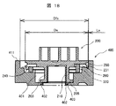
図14は従来のスクロール圧縮機におけるフレームの平面図、図15は図14のX3−X3線矢視断面図、図16は従来のスクロール圧縮機における旋回スクロールの断面図で、図17のY3−O−Y3線から矢視方向に見た断面図、図17は図16に示す旋回スクロールの背面図(下面図)、図18は図17のY3−O−Y3線に沿った部分に相当するフレーム部分と旋回スクロールの断面図である。従来のスクロール圧縮機の基本的な構造は図1と同様であり、図1と同一部分については同一符号を付してその説明を省略する。
Here, the structure of the conventional scroll compressor will be described with reference to FIGS.
14 is a plan view of a frame in a conventional scroll compressor, FIG. 15 is a cross-sectional view taken along line X3-X3 in FIG. 14, and FIG. 16 is a cross-sectional view of a turning scroll in the conventional scroll compressor. FIG. 17 is a rear view (bottom view) of the orbiting scroll shown in FIG. 16, and FIG. 18 corresponds to a portion along the line Y3-O-Y3 of FIG. It is sectional drawing of a frame part and a turning scroll. The basic structure of the conventional scroll compressor is the same as in FIG. 1, and the same parts as those in FIG.
図14及び図15はフレーム400の構造を示す図で、図14に示すように、フレーム400外周部のボルト座411には周方向に複数個のボルト穴412がほぼ等間隔に形成されており、このボルト穴412を使用することにより固定スクロール100を前記フレーム400に締結ボルト(図示せず)で締結するようにしている。414は前記フレーム400の外周面の一部に形成されたガス通路で、このガス通路414を介して、密閉容器700上部の吐出室に吐出されたガスや油を、圧縮機構部2下部の電動機部3が設けられている空間に導くように構成している。409は旋回スクロール200が着座する着座面で、図14に示すように、この着座面409は、前記オルダムリング500のキー部分が係合されるキー溝415が形成されている部分を除いて、周方向に円形状に設けられている。なお、Dfaはフレーム400のボルト座411内周面の直径である。
14 and 15 show the structure of the
また、図15に示すように、フレーム400における旋回スクロール200のボス部203下面に対向する部分にはシールリング溝402が設けられており、このシールリング溝402は、前記回転軸300が貫通する穴の周りに円形に形成されており、該シールリング溝402には前記シールリング403が挿入される。
As shown in FIG. 15, a
図16及び図17は旋回スクロール200の構造を示す図で、これらの図に示すように、旋回スクロール200の背面外周側には、オルダムリング500のキー部分が係合されるキー溝260が、互いに180°反対側に位置して2個所設けられている(図17参照)。また、前記旋回スクロール200の背面外周側には、図17に示すように、旋回スクロール200の台板201の背面から外周面に至る放射溝240が周方向に多数設けられている。
FIGS. 16 and 17 are views showing the structure of the
また、前記旋回スクロール200の台板201外周面(側面)には前記放射溝240及び前記キー溝260と交差して周方向に延びる円周溝250が形成されており、この円周溝250が形成されることにより、前記放射溝240及び前記キー溝260と前記円周溝250とを連通する角穴231が形成されている。
Further, a
更に、図16、図17に示すように、旋回スクロール200のボス部203下端面には給油ポケット205が周方向に複数個(この例では4箇)形成されている。なお、図16に示すDsは旋回スクロール台板201の外周面の直径である。
Further, as shown in FIGS. 16 and 17, a plurality of (four in this example) oil supply pockets 205 are formed in the circumferential direction on the lower end surface of the
図18は、図17のY3−O−Y3線に沿った部分に相当するフレーム400部分に旋回スクロール200を組み込んだ図である。この図において、Dfaは図15に示すフレーム400のボルト座411内周面の直径、Dsは図16に示す旋回スクロール台板201の外周面の直径である。また、Laは旋回スクロール台板201の外周面とフレーム400のボルト座411内周面との隙間である。
FIG. 18 is a diagram in which the
スクロール圧縮機1においては、旋回スクロール200が旋回運動する際に、旋回スクロール200の台板201外周面とフレーム400との間の隙間Laに油が噛み込み、この油が旋回スクロール200の旋回運動により攪拌されて撹拌損失が増大する。この撹拌損失を低減するために、前記放射溝240は設けられている。
In the
即ち、旋回スクロール200が旋回運動する際に、旋回スクロール200の台板201の外周面とフレーム400の内周面との隙間Laに噛み込む油を、前記放射溝240を通して、前記旋回スクロール200の背面側に逃すことにより、攪拌損失を低減するようにしている。
That is, when the
しかし、このように構成した従来のスクロール圧縮機においては、前述したように、旋回スクロールの台板背面に多数の前記放射溝240などが設けられているため、旋回スクロール台板201の剛性が低くなり、旋回スクロール台板201と固定スクロール鏡板面105との間に隙間が生じて、ガス漏れが増加し体積効率が低下する。この体積効率低下の防止のため、旋回スクロール台板201の平面度を高精度加工する必要があり、前記放射溝240の加工工数だけではく、台板の高精度加工も必要となるから、高価なものになるという課題がある。
However, in the conventional scroll compressor configured as described above, as described above, since the multiple
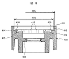
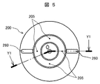
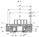
そこで、本発明の実施例1においては、旋回スクロールによる油の攪拌損失を低減しつつ、簡単な構造で体積効率の低下を防止して安価に製作できるスクロール圧縮機とするため、以下の図2〜図7で説明する構成としている。図2は本発明のスクロール圧縮機の実施例1におけるフレームの平面図、図3は図2のX1−X1線矢視断面図、図4は実施例1のスクロール圧縮機における旋回スクロールの断面図で、図5のY1−O−Y1線から矢視方向に見た断面図、図5は図4に示す旋回スクロールの背面図(下面図)、図6は図5のY1−O−Y1線に沿った部分に相当するフレーム部分と旋回スクロールの断面図、図7は図6のA部拡大図である。 Therefore, in the first embodiment of the present invention, in order to provide a scroll compressor that can be manufactured at low cost while preventing a decrease in volumetric efficiency with a simple structure while reducing oil agitation loss due to orbiting scroll, the following FIG. -It is set as the structure demonstrated in FIG. 2 is a plan view of a frame in the first embodiment of the scroll compressor of the present invention, FIG. 3 is a cross-sectional view taken along line X1-X1 in FIG. 2, and FIG. 4 is a cross-sectional view of the orbiting scroll in the scroll compressor of the first embodiment. 5 is a cross-sectional view taken in the direction of the arrow from the Y1-O-Y1 line in FIG. 5, FIG. 5 is a rear view (bottom view) of the orbiting scroll shown in FIG. 4, and FIG. 6 is a Y1-O-Y1 line in FIG. FIG. 7 is an enlarged view of a portion A in FIG. 6.
これらの図において、上述した図1、図14〜図18と同一符号を付した部分は同一或いは相当する部分であり、同一部分についての説明は省略する。 In these drawings, the portions denoted by the same reference numerals as those in FIGS. 1 and 14 to 18 described above are the same or corresponding portions, and the description of the same portions is omitted.
図2及び図3は本実施例1におけるフレーム400の構造を示す図である。本実施例においても、図2に示すように、フレーム400外周部に形成されているボルト座411には周方向に複数個のボルト穴412がほぼ等間隔に形成されており、このボルト穴412を使用することにより固定スクロール100を前記フレーム400に締結ボルトで締結する点では図14に示す従来のスクロール圧縮機と同様である。
2 and 3 are diagrams showing the structure of the
しかし、本実施例においては、周方向にほぼ等間隔に設けられている前記ボルト穴412の部分のボルト座411の間、即ち旋回スクロール200外周面と対向する前記ボルト穴412間のフレーム400内周面に、それぞれ周方向の溝(周方向溝)410を設けている。また、前記ボルト穴412を形成しているボルト座411の部分に対応するボルト座内周側下部のフレーム400の部分には、前記周方向溝の油を、前記旋回スクロールの背面側空間に逃がすための逃げ溝413が形成されている。
However, in the present embodiment, the inside of the
なお、図2、図3において、Dfaはフレーム400のボルト穴412部分におけるボルト座411部分の内周面直径、Dfbは前記周方向溝410の部分の内径である。
2 and 3, Dfa is the inner peripheral surface diameter of the
図4及び図5は旋回スクロール200の構造を示す図である。本実施例においては、旋回スクロール200には、前述した図16や図17に示す従来のスクロール圧縮機に示すような、旋回スクロール200の台板201の背面から外周面に至る多数の放射溝240、旋回スクロール台板外周面に形成された円周溝250、前記放射溝と前記円周溝とを連通する角穴231などが形成されておらず、旋回スクロール台板201にはオルダムリング500と係合するキー溝260が形成されているだけである。なお、図4に示すDsは旋回スクロール台板201の外周面の直径である。
4 and 5 are diagrams showing the structure of the
図6は、図5のY1−O−Y1線に沿った部分に相当するフレーム400部分に旋回スクロール200を組み込んだ図である。この図において、Dfaは図2及び図3に示すフレーム400のボルト穴412部分におけるボルト座411内周面の直径、Dfbは前記周方向溝410の部分の直径である。また、Laは旋回スクロール台板201の外周面とボルト穴412の部分のボルト座411内周面との隙間、Lbは旋回スクロール台板201の外周面と周方向溝410との隙間である。
FIG. 6 is a diagram in which the
なお、図7は図6のA部の拡大図であり、周方向溝410に溜まった油は、旋回スクロール200の着座面409に形成された逃げ溝413(図2参照)などを介して、旋回スクロール200の背面の背圧室401に容易に逃がすことができるように構成されている。
7 is an enlarged view of a portion A in FIG. 6, and the oil accumulated in the
スクロール圧縮機1においては、前述したように、旋回スクロール200が旋回運動する際に、旋回スクロール200の台板201外周面とフレーム400に形成したボルト座411との間の隙間に油が噛み込み、この油が旋回スクロール200の旋回運動により攪拌されて撹拌損失が増大する。この撹拌損失を低減するために、本実施例では、前記旋回スクロール台板201外周面と対向する前記フレーム400の内周面、即ち前記ボルト穴412の部分のボルト座411間に、周方向溝410を形成している。これにより、旋回スクロール台板201外周面とフレーム400との隙間に噛み込む油を、前記周方向溝410により周方向に逃がし、更に前記旋回スクロール台板201の外周面とフレーム400内周面との隙間がより大きくなっている部分から前記油を旋回スクロール背面側の空間に逃がすことができる。従って、本実施例によれば、攪拌損失を低減できるから、体積効率の低下を防止してスクロール圧縮機の効率向上を図ることができる。
In the
また、本実施例によれば、従来のスクロール圧縮機のように、旋回スクロールの台板に多数の放射溝240、円周溝250、角穴231などを設ける必要がないので、旋回スクロール台板201の剛性が低下するのを防止でき、旋回スクロール台板201の平面度を高精度加工する必要もなくなるから、加工コストを低減して、スクロール圧縮機を安価に製作することもできる。しかも、本実施例によれば、旋回スクロール台板201の剛性低下を防止できることから、台板201を厚くすることなくその変形を防止でき、固定スクロール100と接する旋回スクロール台板201の平面度を良好に確保することができる。従って、旋回スクロール台板201と固定スクロール台板201の鏡板面105との接触部からのガス漏れを抑制することができ、この点からも体積効率を向上できる。
Further, according to this embodiment, unlike the conventional scroll compressor, it is not necessary to provide a large number of
更に、本実施例によれば、前記ボルト穴412を形成しているボルト座411の部分に対応するボルト座内周側下部のフレーム部分(着座面409)に、前記周方向溝410の油を、前記旋回スクロールの背面側空間に逃がすための逃げ溝413を形成している。従って、旋回スクロール200の台板外周面とフレーム400内周面との間に噛み込んで前記周方向溝410に流れた油を、前記逃げ溝413からスムーズに旋回スクロールの背面側空間に逃がすことができ、これにより更に撹拌損失を低減して、スクロール圧縮機の効率を更に向上できる効果も得られる。
Further, according to this embodiment, the oil in the
なお、前記周方向溝410は、前記フレーム400を鋳造で製作する際に併せて製作することができ、この鋳造で製作された周方向溝410はその材料の素材のまま無加工面として製作することができるから、前記周方向溝410を形成しても加工コストをほとんど増加させることはなく、この点からもスクロール圧縮機を安価に製作することが可能となる。
The
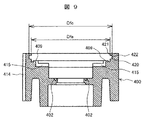
本発明のスクロール圧縮機の実施例2を図8〜図13により説明する。図8は本発明のスクロール圧縮機の実施例2におけるフレームの平面図、図9は図8のX2−X2線矢視断面図、図10は実施例2のスクロール圧縮機における旋回スクロールの断面図で、図11のY2−O−Y2線から矢視方向に見た断面図、図11は図10に示す旋回スクロールの背面図(下面図)、図12は図11のY2−O−Y2線に沿った部分に相当するフレーム部分と旋回スクロールの断面図、図13は図12のB部拡大図である。 A scroll compressor according to a second embodiment of the present invention will be described with reference to FIGS. 8 is a plan view of a frame in the second embodiment of the scroll compressor of the present invention, FIG. 9 is a cross-sectional view taken along the line X2-X2 in FIG. 8, and FIG. 10 is a cross-sectional view of the orbiting scroll in the scroll compressor of the second embodiment. 11 is a cross-sectional view taken in the direction of the arrow from the line Y2-O-Y2 in FIG. 11, FIG. 11 is a rear view (bottom view) of the orbiting scroll shown in FIG. 10, and FIG. 12 is a line Y2-O-Y2 in FIG. FIG. 13 is an enlarged view of a portion B in FIG. 12.
これらの図において、上述した図1〜図7、図14〜図18と同一符号を付した部分は同一或いは相当する部分であり、同一部分についての説明は省略する。 In these drawings, the parts denoted by the same reference numerals as those in FIGS. 1 to 7 and FIGS. 14 to 18 are the same or corresponding parts, and the description of the same parts is omitted.
図8及び図9は本実施例2におけるフレーム400の構造を示す図である。本実施例においても、図8に示すように、フレーム400外周部に形成されているボルト座411には周方向に複数個のボルト穴412がほぼ等間隔に形成されており、このボルト穴412を使用することにより固定スクロール100を前記フレーム400に締結ボルトで締結する点では図14に示す従来のスクロール圧縮機、図2に示す上記実施例1に示すスクロール圧縮機と同様である。
8 and 9 are diagrams showing the structure of the
本実施例2が上記実施例1と異なる点は、図8及び図9に示すように、フレーム400のボルト座411内周面における旋回スクロール200の台板外周面と対向する部分に、円形の周方向溝(円周溝)420を設けていることである。前記実施例1では、周方向溝が、ボルト穴412間に形成された複数の周方向溝410により構成しているが、本実施例2では周方向溝を、円形の1つの周方向溝420、即ち円周溝で形成している。
As shown in FIGS. 8 and 9, the second embodiment is different from the first embodiment in that a circular portion is formed in a portion of the inner peripheral surface of the
また、前記周方向溝(円周溝)420は、本実施例では、第1の直径を有する第1の円周面421と、前記第1の直径よりも大きな第2の直径を有する第2の円周面422により構成されている。即ち、前記周方向溝420は、フレーム400のボルト座411内周面の直径(第1の直径)Dfaで形成される第1の円周面421と、前記第1の直径Dfaよりも大きな第2の直径Dfcで形成される第2の円周面422で構成されている。また、前記第1の円周面421よりも下側に前記第2の円周面422が設けられている。
In the present embodiment, the circumferential groove (circumferential groove) 420 includes a first
図10及び図11は旋回スクロール200の構造を示す図である。本実施例においても、旋回スクロール200の構造は、前述した図4や図5に示す上記実施例1における旋回スクロールと同じである。なお、図10に示すDsは旋回スクロール台板201の外周面の直径である。
10 and 11 are diagrams showing the structure of the
図12は、図11のY2−O−Y2線に沿った部分に相当するフレーム400部分に旋回スクロール200を組み込んだ図である。この図において、Dfa,Dfc,Dsは図8〜図10に示すものと同一である。また、Lcは旋回スクロール台板201の外周面と周方向溝410(の底部)との隙間である。
FIG. 12 is a diagram in which the
図13は図12のB部の拡大図であり、旋回スクロール台板201の外周面とフレーム400の内周面との間に噛み込んだ油は、周方向溝(円周溝)420を通って周方向に流れた後、旋回スクロール200の背面の背圧室401に容易に逃がすことができる。
FIG. 13 is an enlarged view of a portion B in FIG. 12, and the oil caught between the outer peripheral surface of the orbiting
本実施例2においても、上記実施例1と同様の効果を得ることができる。即ち、旋回スクロール台板201の外周面とフレーム400の内周面との間に噛み込む油を攪拌することによる撹拌損失の低減を図ることができる。また、旋回スクロール200には、従来のように多数の放射溝、円周溝、角穴などを設ける必要がないので、旋回スクロール台板201の剛性低下も抑制して台板201の変形を防止できる。従って、旋回スクロール台板201の平面度を高精度加工する必要もなくなり、スクロール圧縮機を安価に製作できるなどの効果が得られる。
Also in the second embodiment, the same effect as in the first embodiment can be obtained. That is, it is possible to reduce agitation loss by agitating the oil biting between the outer peripheral surface of the orbiting
更に、本実施例2によれば、周方向溝420を周方向に均一な断面積の円周溝に構成しているから、旋回スクロール台板201の外周面とフレーム400の内周面との間に噛み込む油を、前記周方向溝420を介して周方向にスムーズに排出できるという効果もある。なお、本実施例2のように構成するためには、ボルト穴412の部分よりも内径側に前記周方向溝420を形成する必要があるため、フレーム400の外径は実施例1と比べ大きくなる傾向にはなるので、スクロール圧縮機を小型化したい場合には上記実施例1の構成とすることが好ましい。これに対し本実施例2は、単一の円周溝(周方向溝)を形成すれば良いので、機械加工で製作する場合などには加工が容易になる利点もある。
Furthermore, according to the second embodiment, since the
なお、本発明は上述した実施例に限定されるものではなく、様々な変形例が含まれる。また、ある実施例の構成の一部を他の実施例の構成に置き換えることが可能であり、ある実施例の構成に他の実施例の構成を加えることも可能である。
更に、上記した実施例は本発明を分かりやすく説明するために詳細に説明したものであり、必ずしも説明した全ての構成を備えるものに限定されるものではない。
In addition, this invention is not limited to the Example mentioned above, Various modifications are included. Further, a part of the configuration of one embodiment can be replaced with the configuration of another embodiment, and the configuration of another embodiment can be added to the configuration of one embodiment.
Further, the above-described embodiments have been described in detail for easy understanding of the present invention, and are not necessarily limited to those having all the configurations described.
1:スクロール圧縮機、2:圧縮機構部、3:電動機部、
100:固定スクロール、101:台板、102:ラップ、
103:吸入口、104:吐出口、
105:固定スクロールの鏡板面、130:圧縮室、
200:旋回スクロール、201:台板、202:ラップ、203:ボス部、
205:給油ポケット、210:旋回軸受、231:角穴、240:放射溝、
250:円周溝、260:キー溝、
300:回転軸、301:クランクピン、302:主軸部、
310:ポンプ継手、311:回転軸内の油通路、312:横穴、
400:フレーム、401:背圧室、402:シールリング溝、403:シールリング、
404:バランスウェイト、405:バランスウェイトカバ、
406:フレームシール、407:ボルト、408:排油パイプ、
409:着座面、410:周方向溝、411:ボルト座、412:ボルト穴、
413:逃げ溝、414:ガス通路、415:キー溝、
420:周方向溝(円周溝)、421:第1の円周面、422:第2の円周面、
500:オルダムリング、510:主軸受(転がり軸受)、520:スラスト軸受、
600:電動機、601:ステータ、602:ロータ、
700:密閉容器、701:吐出管、702:ハーメ端子、703:端子カバ、
710:上キャップ、711:吸入管、720:下キャップ、721脚部、
730:油溜り、
801下フレームハウジング、800:副軸受部、802:ハウジング、
803:副軸受(転がり軸受)、804:ハウジングカバ、805:ボルト、
900:ポンプ部、910:ボルト、
Ds:旋回スクロール台板外周面の直径、
Dfa:フレームのボルト座内周面の直径(第1の円周面の直径)、
Dfb:周方向溝の部分の直径、
Dfc:周方向溝の部分の直径(第2の円周面の直径)、
La:旋回スクロール台板外周面とボルト穴部分のボルト座内周面との隙間、
Lb:旋回スクロール台板外周面と周方向溝との隙間、
Lc:旋回スクロール台板外周面と周方向溝との隙間。
1: scroll compressor, 2: compression mechanism, 3: electric motor,
100: fixed scroll, 101: base plate, 102: lap,
103: suction port, 104: discharge port,
105: End plate surface of fixed scroll, 130: Compression chamber,
200: Orbiting scroll, 201: Base plate, 202: Lap, 203: Boss part,
205: Refueling pocket, 210: Slewing bearing, 231: Square hole, 240: Radiation groove,
250: circumferential groove, 260: key groove,
300: Rotating shaft, 301: Crank pin, 302: Main shaft part,
310: Pump joint, 311: Oil passage in the rotating shaft, 312: Side hole,
400: Frame, 401: Back pressure chamber, 402: Seal ring groove, 403: Seal ring,
404: Balance weight, 405: Balance weight cover,
406: Frame seal, 407: Bolt, 408: Oil drain pipe,
409: seating surface, 410: circumferential groove, 411: bolt seat, 412: bolt hole,
413: Escape groove, 414: Gas passage, 415: Key groove,
420: circumferential groove (circumferential groove), 421: first circumferential surface, 422: second circumferential surface,
500: Oldham ring, 510: Main bearing (rolling bearing), 520: Thrust bearing,
600: Electric motor, 601: Stator, 602: Rotor,
700: Airtight container, 701: Discharge pipe, 702: Hermetic terminal, 703: Terminal cover,
710: upper cap, 711: suction pipe, 720: lower cap, 721 leg,
730: oil sump,
801 lower frame housing, 800: auxiliary bearing, 802: housing,
803: Secondary bearing (rolling bearing), 804: Housing cover, 805: Bolt,
900: Pump part, 910: Bolt,
Ds: Diameter of the outer peripheral surface of the orbiting scroll base plate,
Dfa: the diameter of the inner peripheral surface of the bolt seat of the frame (the diameter of the first circumferential surface),
Dfb: the diameter of the circumferential groove part,
Dfc: diameter of the circumferential groove portion (diameter of the second circumferential surface),
La: A clearance between the outer peripheral surface of the orbiting scroll base plate and the inner peripheral surface of the bolt seat at the bolt hole portion,
Lb: A gap between the outer peripheral surface of the orbiting scroll base plate and the circumferential groove,
Lc: A gap between the outer peripheral surface of the orbiting scroll base plate and the circumferential groove.
Claims (5)
旋回スクロールの台板外周面と対向する前記フレームの内周面に周方向溝が形成され、
前記周方向溝の油を、前記旋回スクロールの背面側空間に逃がすための逃げ溝を前記フレームに形成し、且つ
前記周方向溝は連続する円形の円周溝で形成されると共に、前記周方向溝は、第1の直径を有する連続する円形の第1の円周面と、前記第1の直径よりも大きな第2の直径を有する連続する円形の第2の円周面により構成されていることを特徴とするスクロール圧縮機。 A fixed scroll, a turning scroll, and a frame are provided, and the fixed scroll is fixed to the frame, and the turning scroll is disposed in a space between the fixed scroll and the frame so as to make a turning motion while meshing with the fixed scroll. In a scroll compressor comprising: a compression mechanism portion configured as follows; an electric motor portion for driving the compression mechanism portion; and a sealed container that accommodates the compression mechanism portion and the electric motor portion inside.
A circumferential groove is formed on the inner peripheral surface of the frame facing the outer peripheral surface of the base plate of the orbiting scroll ,
A relief groove is formed in the frame for allowing the oil in the circumferential groove to escape to the back side space of the orbiting scroll; and
The circumferential groove is formed by a continuous circular circumferential groove, and the circumferential groove is a continuous circular first circumferential surface having a first diameter and larger than the first diameter. A scroll compressor comprising a continuous circular second circumferential surface having a second diameter .
Priority Applications (1)
| Application Number | Priority Date | Filing Date | Title |
|---|---|---|---|
| JP2014255187A JP6437295B2 (en) | 2014-12-17 | 2014-12-17 | Scroll compressor |
Applications Claiming Priority (1)
| Application Number | Priority Date | Filing Date | Title |
|---|---|---|---|
| JP2014255187A JP6437295B2 (en) | 2014-12-17 | 2014-12-17 | Scroll compressor |
Publications (3)
| Publication Number | Publication Date |
|---|---|
| JP2016114019A JP2016114019A (en) | 2016-06-23 |
| JP2016114019A5 JP2016114019A5 (en) | 2017-08-03 |
| JP6437295B2 true JP6437295B2 (en) | 2018-12-12 |
Family
ID=56141160
Family Applications (1)
| Application Number | Title | Priority Date | Filing Date |
|---|---|---|---|
| JP2014255187A Active JP6437295B2 (en) | 2014-12-17 | 2014-12-17 | Scroll compressor |
Country Status (1)
| Country | Link |
|---|---|
| JP (1) | JP6437295B2 (en) |
Families Citing this family (1)
| Publication number | Priority date | Publication date | Assignee | Title |
|---|---|---|---|---|
| WO2018051502A1 (en) * | 2016-09-16 | 2018-03-22 | 三菱電機株式会社 | Compressor |
Family Cites Families (2)
| Publication number | Priority date | Publication date | Assignee | Title |
|---|---|---|---|---|
| JPS59119091A (en) * | 1982-12-24 | 1984-07-10 | Hitachi Ltd | Scroll type fluid machine |
| JP2008190467A (en) * | 2007-02-06 | 2008-08-21 | Mitsubishi Heavy Ind Ltd | Hermetic electric compressor |
-
2014
- 2014-12-17 JP JP2014255187A patent/JP6437295B2/en active Active
Also Published As
| Publication number | Publication date |
|---|---|
| JP2016114019A (en) | 2016-06-23 |
Similar Documents
| Publication | Publication Date | Title |
|---|---|---|
| US9624928B2 (en) | Scroll-type compressor with gas passage formed in orbiting plate to restrict flow from compression chamber to back pressure chamber | |
| JP5260608B2 (en) | Scroll compressor | |
| US10458407B2 (en) | Scroll compressor with different chamfered corners | |
| US20160003247A1 (en) | Scroll Compressor | |
| US20150322947A1 (en) | Scroll-Type Fluid Machine | |
| JP2008303844A (en) | Scroll fluid machine | |
| JP6042530B2 (en) | Scroll compressor | |
| JP6554926B2 (en) | Scroll compressor | |
| KR20180101901A (en) | Scroll compressor | |
| JP6437295B2 (en) | Scroll compressor | |
| JP2014029117A (en) | Scroll compressor | |
| WO2017208455A1 (en) | Scroll compressor | |
| JP2008121481A (en) | Scroll fluid machine | |
| JP2011190779A (en) | Scroll fluid machine | |
| JP4433457B2 (en) | Scroll compressor | |
| JP2007132233A (en) | Scroll compressor | |
| JP2007162679A (en) | Fluid machine | |
| JP2005140064A (en) | Electric compressor | |
| JP4593448B2 (en) | Refrigerant compressor | |
| JP5764715B2 (en) | Scroll compressor | |
| JP2004003525A (en) | Scroll compressor | |
| JP2010001816A (en) | Scroll fluid machine | |
| JP5147489B2 (en) | Scroll compressor | |
| JP2004100660A (en) | Scroll compressor | |
| JP2005163687A (en) | Electric compressor and its manufacturing method |
Legal Events
| Date | Code | Title | Description |
|---|---|---|---|
| A711 | Notification of change in applicant |
Free format text: JAPANESE INTERMEDIATE CODE: A711 Effective date: 20160404 |
|
| A521 | Written amendment |
Free format text: JAPANESE INTERMEDIATE CODE: A523 Effective date: 20170621 |
|
| A621 | Written request for application examination |
Free format text: JAPANESE INTERMEDIATE CODE: A621 Effective date: 20170621 |
|
| A711 | Notification of change in applicant |
Free format text: JAPANESE INTERMEDIATE CODE: A711 Effective date: 20171018 |
|
| A977 | Report on retrieval |
Free format text: JAPANESE INTERMEDIATE CODE: A971007 Effective date: 20180406 |
|
| A131 | Notification of reasons for refusal |
Free format text: JAPANESE INTERMEDIATE CODE: A131 Effective date: 20180417 |
|
| A521 | Written amendment |
Free format text: JAPANESE INTERMEDIATE CODE: A523 Effective date: 20180618 |
|
| TRDD | Decision of grant or rejection written | ||
| A01 | Written decision to grant a patent or to grant a registration (utility model) |
Free format text: JAPANESE INTERMEDIATE CODE: A01 Effective date: 20181023 |
|
| A61 | First payment of annual fees (during grant procedure) |
Free format text: JAPANESE INTERMEDIATE CODE: A61 Effective date: 20181114 |
|
| R150 | Certificate of patent or registration of utility model |
Ref document number: 6437295 Country of ref document: JP Free format text: JAPANESE INTERMEDIATE CODE: R150 |


