EP2979785B1 - Polygon machining device and polygon machining method - Google Patents
Polygon machining device and polygon machining method Download PDFInfo
- Publication number
- EP2979785B1 EP2979785B1 EP14775453.5A EP14775453A EP2979785B1 EP 2979785 B1 EP2979785 B1 EP 2979785B1 EP 14775453 A EP14775453 A EP 14775453A EP 2979785 B1 EP2979785 B1 EP 2979785B1
- Authority
- EP
- European Patent Office
- Prior art keywords
- polygon
- machining
- main shaft
- tool
- cutter
- Prior art date
- Legal status (The legal status is an assumption and is not a legal conclusion. Google has not performed a legal analysis and makes no representation as to the accuracy of the status listed.)
- Active
Links
Images
Classifications
-
- B—PERFORMING OPERATIONS; TRANSPORTING
- B23—MACHINE TOOLS; METAL-WORKING NOT OTHERWISE PROVIDED FOR
- B23B—TURNING; BORING
- B23B5/00—Turning-machines or devices specially adapted for particular work; Accessories specially adapted therefor
- B23B5/36—Turning-machines or devices specially adapted for particular work; Accessories specially adapted therefor for turning specially-shaped surfaces by making use of relative movement of the tool and work produced by geometrical mechanisms, i.e. forming-lathes
-
- B—PERFORMING OPERATIONS; TRANSPORTING
- B23—MACHINE TOOLS; METAL-WORKING NOT OTHERWISE PROVIDED FOR
- B23Q—DETAILS, COMPONENTS, OR ACCESSORIES FOR MACHINE TOOLS, e.g. ARRANGEMENTS FOR COPYING OR CONTROLLING; MACHINE TOOLS IN GENERAL CHARACTERISED BY THE CONSTRUCTION OF PARTICULAR DETAILS OR COMPONENTS; COMBINATIONS OR ASSOCIATIONS OF METAL-WORKING MACHINES, NOT DIRECTED TO A PARTICULAR RESULT
- B23Q27/00—Geometrical mechanisms for the production of work of particular shapes, not fully provided for in another subclass
- B23Q27/006—Geometrical mechanisms for the production of work of particular shapes, not fully provided for in another subclass by rolling without slippage two bodies of particular shape relative to each other
-
- B—PERFORMING OPERATIONS; TRANSPORTING
- B23—MACHINE TOOLS; METAL-WORKING NOT OTHERWISE PROVIDED FOR
- B23B—TURNING; BORING
- B23B2265/00—Details of general geometric configurations
- B23B2265/16—Elliptical
-
- B—PERFORMING OPERATIONS; TRANSPORTING
- B23—MACHINE TOOLS; METAL-WORKING NOT OTHERWISE PROVIDED FOR
- B23B—TURNING; BORING
- B23B2265/00—Details of general geometric configurations
- B23B2265/32—Polygonal
-
- G—PHYSICS
- G05—CONTROLLING; REGULATING
- G05B—CONTROL OR REGULATING SYSTEMS IN GENERAL; FUNCTIONAL ELEMENTS OF SUCH SYSTEMS; MONITORING OR TESTING ARRANGEMENTS FOR SUCH SYSTEMS OR ELEMENTS
- G05B2219/00—Program-control systems
- G05B2219/30—Nc systems
- G05B2219/45—Nc applications
- G05B2219/45236—Facing, polygon working, polyhedron machining
-
- Y—GENERAL TAGGING OF NEW TECHNOLOGICAL DEVELOPMENTS; GENERAL TAGGING OF CROSS-SECTIONAL TECHNOLOGIES SPANNING OVER SEVERAL SECTIONS OF THE IPC; TECHNICAL SUBJECTS COVERED BY FORMER USPC CROSS-REFERENCE ART COLLECTIONS [XRACs] AND DIGESTS
- Y10—TECHNICAL SUBJECTS COVERED BY FORMER USPC
- Y10T—TECHNICAL SUBJECTS COVERED BY FORMER US CLASSIFICATION
- Y10T82/00—Turning
- Y10T82/10—Process of turning
Definitions
- the present invention relates to a polygon machining device and a polygon machining method.
- Polygon machining in which the outer peripheral surface of a workpiece is machined into a polygon or the like by using a polygon cutter is conventional. Polygon machining is carried out by rotating a workpiece gripped by a main shaft about the shaft line and by synchronously rotating the polygon cutter mounted to a tool spindle in a predetermined rotation ratio with respect to the workpiece.
- Patent Document 1 There is a polygon machining method in which polygon machining is carried out after matching the phase of a workpiece with that of the polygon cutter between each piece of the polygon machining in the case where a plurality of kinds of polygon machining is carried out on the outer peripheral surface of a workpiece, see e.g. patent publication JP 5080120 (Patent Document 1).
- Laid-open publication JP 2008-264937 A discloses a polygon machining device according to the preamble of claim 1 and a polygon machining method according to the preamble of claim 4.
- the invention solves this problem by providing a polygon machining device including the features of claim 1, and a polygon machining method including the features of claim 4.
- the synchronization ratio changing unit may be configured so as to change the ratio of synchronization at the timing when the rotation position of the main shaft is located at a predetermined fixed point.
- the second ratio may be set so that the rotation speed of the main shaft is higher than the rotation speed of the tool spindle.
- the present invention it is possible to implement a polygon machining device and a polygon machining method for carrying out polygon machining on a workpiece gripped by a main shaft that rotates by using a polygon cutter mounted to a tool spindle that rotates in synchronization with the main shaft.
- a polygon machining device and a polygon machining method for carrying out polygon machining on a workpiece gripped by a main shaft that rotates by using a polygon cutter mounted to a tool spindle that rotates in synchronization with the main shaft.
- two kinds of polygon machining are carried out on the outer peripheral surface of a workpiece, it is possible to easily match the phase of the workpiece with the phase of the polygon cutter at both points in time, and therefore it is possible to accurately form a plurality of polygonal shapes in a predetermined phase relationship on the outer peripheral surface of the workpiece.
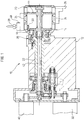
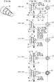
- FIG. 1 is a section view illustrating an example of a configuration of a turret cutter holder that is mounted on a machine tool to which a polygon machining device according to the present invention can be applied.
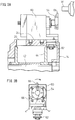
- FIGs. 2A and 2B are diagrams illustrating a state where a polygon cutter that is used in the polygon machining device according to an embodiment of the present invention is mounted to the turret cutter holder illustrated in FIG. 3 , and FIG. 2A is a partial cutout side view and FIG. 2B is a partial cutout front view.
- a turret cutter holder 10 is mounted on an automatic lathe, such as an NC lathe, which is a machine tool.
- the turret cutter holder 10 includes a cutter table main body 12 and a turret 14 that is supported revolvably by the cutter table main body 12.
- the turret 14 has a hollow head part 20 having an outline in the shape of a column or prism and a shaft part 22 in the shape of a hollow cylinder extended concentrically in the shaft line direction from one end in the shaft line direction of the head part 20.
- a plurality of tool mount parts 24 to which a tool is mounted is provided for each predetermined indexed angle. It is possible to selectively mount a machining tool, such as a cutting tool 26, and a rotary tool 28, such as a drill and a milling cutter, to each tool mount part 24.
- the shaft part 22 is supported by the cutter table main body 12 rotatably and movably in the shaft line direction.
- the turret 14 is engaged with the cutter table main body 12 so as to be capable of being disengaged therefrom via an engagement part 38, and by disengaging the engagement part 38 by a servomotor 32 and by rotationally driving the shaft part 22, the turret 14 is driven revolvably.
- the turret 14 is fixed in the indexed position on the cutter table main body 12, and therefore it is possible to select a predetermined machining tool, by causing the engagement part 38 to engage in a predetermined revolving position of the turret 14.
- a drive shaft 42 that is driven rotationally by a servomotor 46 is supported pivotally.
- a driven gear 50 that is linked to the tool spindle engages with a drive gear 44 attached to the drive shaft 42 and the rotary tool 28 is driven rotationally by the servomotor 46.
- a polygon cutter 54 via a holder 60 including the tool spindle.
- a driven gear 62 that is linked to the polygon cutter 54 (tool spindle) via the power transmission within the holder 60 engages with the drive gear 44, the polygon cutter 54 is driven rotationally by the servomotor 46.
- a quadrangle is formed on the outer peripheral surface of the workpiece
- the maximum rotation speed of the tool spindle is set lower than the maximum rotation speed of the main shaft, and therefore in the case where the main shaft and the tool spindle are in synchronization, the maximum rotation speed of the main shaft is restricted by the maximum rotation speed of the tool spindle as a result.
- the synchronization between the main shaft and the tool spindle is released and the main shaft is driven rotationally at a rotation speed necessary for the cutting machining independently of the tool spindle.
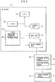
- FIG. 3 is a block diagram illustrating a control unit capable of carrying out the polygon machining method according to the embodiment of the present invention.
- the drive of the tool spindle and the main shaft is controlled by the control unit illustrated in FIG. 3 .
- the control unit includes an NC device 70 mounted on a numerical control (NC) lathe in the present embodiment.
- NC numerical control
- the NC device 70 includes an input unit 72, a display unit 74, a processing unit (CPU) 76, a storage unit (ROM 78 and RAM 80), a drive control unit 82, etc.
- the CPU 76 outputs an operation command to the drive control unit 82 based on various kinds of data, machining programs, etc., stored in the ROM 78 or the RAM 80, and the control unit 82 controls the indexing drive source (servomotor) 32 and the rotation drive source (servomotor) 46 of the turret cutter holder 10 and, a drive mechanism 88, such as a main shaft motor that drives the main shaft rotationally, respectively, and causes the turret 14 to revolve and the rotary tool 28 (tool spindle) and the main shaft to rotate.
- the control device is configured so as to be capable of switching between the synchronous drive and the asynchronous drive of the servomotor 46 (rotational drive of the rotary tool 28) and the main shaft motor (rotational drive of the main shaft).
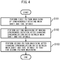
- FIG. 4 is a flowchart illustrating an operation flow of the polygon machining method according to the embodiment of the present invention.
- the synchronization ratio between the main shaft and the tool spindle i.e., the ratio of rotation speed in the state where synchronization is maintained is explained by using a term “ratio”, such as a "first ratio” and a "second ratio”.
- first polygon machining is carried out by the polygon cutter 54 by synchronously rotating the main shaft and the tool spindle so that the rotation speed of the main shaft gripping the workpiece W and the rotation speed of the tool spindle to which the polygon cutter 54 is mounted have a first ratio.
- the first ratio is set to a value that is necessary for carrying out polygon machining to obtain a necessary machined shape (e.g., a polygon).
- cutting machining is carried out on the workpiece on which the first polygon machining has been carried out by synchronously rotating the main shaft and the tool spindle so that the rotation speed of the main shaft and the rotation speed of the tool spindle have a second ratio different from the first ratio at the time of the first polygon machining.
- the polygon cutter mounted to the tool spindle is retracted in advance.
- the "second ratio" used in the cutting machining is explained as follows.
- the polygon cutter 54 is not used, and therefore the synchronization between the main shaft and the tool spindle is not necessary and it is possible to set the rotation speed of the main shaft to a speed higher than that at the time of the polygon machining in an attempt to reduce the time taken by the workpiece machining.
- the rotation speed of the main shaft is set to a speed higher than that at the time of the polygon machining in an attempt to reduce the time taken by the workpiece machining.
- the permitted maximum rotation speed of the tool spindle to which the polygon cutter is mounted is lower than the permitted maximum rotation speed of the main shaft gripping the workpiece.
- the rotation speed of the main shaft is restricted by the permitted maximum rotation speed of the tool spindle in synchronization, and therefore it is not possible to set the rotation speed of the workpiece to a sufficiently high speed.
- the synchronization ratio between the main shaft and the tool spindle is set so that the rotation speed of the main shaft, which is necessary when carrying out the cutting machining, falls within a range that does not exceed the maximum rotation speed permitted for the tool spindle in synchronization.
- synchronization is established so that the polygon cutter is rotated twice while the workpiece is rotated once, but in the cutting machining at step S102, synchronization is established so that the polygon cutter rotates once while the workpiece is rotated, for example, five times, and in this manner, the synchronization ratio is changed between the polygon machining and the cutting machining.
- the second polygon machining is carried out by the polygon cutter by synchronously rotating the main shaft and the tool spindle so that the rotation speed of the main shaft and the rotation speed of the tool spindle have a ratio necessary for the second polygon machining. It is possible to set the ratio at the time of the second polygon machining to the same ratio as the first ratio at step S101.
- the polygon machining device that carries out each piece of the above-described processing includes the main shaft that grips a workpiece, the tool spindle to which a polygon cutter is mounted, and the control unit configured to control the rotation of the main shaft and the tool spindle.
- the control unit controls the rotation of the main shaft and the tool spindle so as to carry out each piece of the above-described processing: the processing (step S101) to carry out the first polygon machining on the workpiece by the polygon cutter by carrying out control to synchronously rotate the main shaft and the tool spindle so that the rotation speed of the main shaft and the rotation speed of the tool spindle have the above-described first ratio necessary to carry out the first polygon machining; the processing (S102) to carry out the cutting machining on the workpiece on which the first polygon machining has been carried out by carrying out control to synchronously rotate the main shaft and the tool spindle so that the rotation speed of the main shaft and the rotation speed of the tool spindle have the above-described second ratio after the first polygon machining; and the processing (step S103) to carry out the second polygon machining by the polygon cutter on the workpiece on which the cutting machining has been carried out by carrying out control to synchronously rotate the main shaft and the tool spindle so that the rotation speed of
- the rotation speed of the main shaft having the second ratio with respect to the rotation speed of the tool spindle is set so that the rotation speed of the main shaft that is necessary for the cutting machining falls within a range in which the rotation speed of the tool spindle does not exceed the maximum rotation speed permitted for the tool spindle.
- the synchronous rotation is made in the first ratio that is necessary for the first polygon machining
- the synchronous rotation is made in the second ratio so that the main shaft can rotate at the rotation speed that is necessary for the cutting machining even if the tool spindle is rotated at a rotation speed lower than the maximum rotation speed
- the synchronous rotation is made in the ratio that is necessary for the second polygon machining. It is also possible to carry out a setting so that the synchronous rotation is made in the first ratio at the time of the second polygon machining.
- the processing at each step is carried out without stopping the synchronous rotation of the main shaft and the tool spindle, and therefore the workpiece and the polygon cutter are rotating in synchronization at all times and in the case where the two kinds of polygon machining are carried out on the outer peripheral surface of the workpiece, it is possible to easily match the phase of the workpiece with that of the polygon cutter, and therefore it is possible to form a plurality of polygonal shapes both accurately and quickly in the predetermined phase relationship on the outer peripheral surface of the workpiece.
- the phase relationship between the main shaft and the tool spindle becomes constant at all times at a predetermined fixed point, by designing the configuration so that the synchronization ratio is changed when the main shaft is located at a predetermined fixed point, for example, the main shaft origin where the rotation angle of the main shaft becomes 0 degrees, and therefore it is possible to easily match the phase at the time of the first polygon machining with the phase at the time of the second polygon machining at the timing when the main shaft is located at the predetermined fixed point. It is also possible to change the synchronization ratio continuously at the predetermined fixed point, or to change the synchronization ratio after temporarily stopping the main shaft.
- FIG. 5A to 5D are diagrams explaining an example in which two kinds of polygon machining are carried out on the workpiece W gripped by the main shaft by using the polygon cutter 54 linked to the tool spindle and including three cutters 66 by the polygon machining method according to the embodiment of the present invention. The case is explained where two hexagons different in size are formed in the same phase on the outer peripheral surface of the workpiece W as illustrated in FIG. 5A .
- an outer diameter cutting tool 57 is indexed and the workpiece W gripped by the main shaft is guided by a guide bush 55 and outer diameter machining (cutting machining) is carried out on the workpiece W.
- the polygon cutter 54 is indexed and the first polygon machining to form a hexagon is carried out on the portion of the workpiece W on which the outer diameter machining has been carried out as illustrated at step S203.
- the main shaft and the tool spindle are synchronously rotated in the first ratio necessary for the first polygon machining.
- the outer diameter cutting tool 57 is indexed and the outer diameter machining (cutting machining) is carried out on the workpiece W.
- the synchronous rotation is made in the second ratio so that the main shaft can rotate at the rotation speed necessary for the cutting machining even if the tool spindle is rotated at a rotation speed lower than the maximum rotation speed.
- the polygon cutter 54 is indexed and the second polygon machining to form a hexagon on the workpiece W is carried out.
- the main shaft and the tool spindle are synchronously rotated in the ratio necessary for the second polygon machining.
- the synchronous rotation is made in the first ratio, which is the same as that in the case of the first polygon machining.
- the phase of the polygon cutter 54 is the same as the phase of the workpiece W when carrying out the first polygon machining and the second polygon machining, and therefore it is possible to carry out the second polygon machining in the predetermined phase with respect to the first polygon machining.
Description
- The present invention relates to a polygon machining device and a polygon machining method.
- Polygon machining in which the outer peripheral surface of a workpiece is machined into a polygon or the like by using a polygon cutter is conventional. Polygon machining is carried out by rotating a workpiece gripped by a main shaft about the shaft line and by synchronously rotating the polygon cutter mounted to a tool spindle in a predetermined rotation ratio with respect to the workpiece.
- There is a polygon machining method in which polygon machining is carried out after matching the phase of a workpiece with that of the polygon cutter between each piece of the polygon machining in the case where a plurality of kinds of polygon machining is carried out on the outer peripheral surface of a workpiece, see e.g. patent publication
JP 5080120 - Laid-open publication
JP 2008-264937 A - As described above, in the case where the polygon machining is carried out on the outer peripheral surface of a workpiece, first, it is necessary to carry out first polygon machining on the workpiece, then carry out deburring machining or the like to remove burrs generated on the outer peripheral surface of the workpiece in the first polygon machining on the workpiece on which the first polygon machining has been carried out, and to carry out second polygon machining to remove burrs generated on the inner peripheral surface of the workpiece in the first polygon machining on the workpiece on which the deburring machining or the like has been carried out after rotating the polygon cutter so that the position of the origin set on the rotary tool table and the polygon cutter are relatively in a predetermined arrangement relationship, and therefore there is a drawback in that the number of processes at the time of machining increases.
- It is the technical problem underlying the invention to provide a polygon machining device and a polygon machining method for carrying out a plurality of pieces of polygon machining on a workpiece gripped by a main shaft that rotates by using a polygon cutter mounted to a tool spindle that rotates in synchronization with the main shaft.
- The invention solves this problem by providing a polygon machining device including the features of claim 1, and a polygon machining method including the features of claim 4.
- The synchronization ratio changing unit may be configured so as to change the ratio of synchronization at the timing when the rotation position of the main shaft is located at a predetermined fixed point.
- Further, the second ratio may be set so that the rotation speed of the main shaft is higher than the rotation speed of the tool spindle.
- According to the present invention, it is possible to implement a polygon machining device and a polygon machining method for carrying out polygon machining on a workpiece gripped by a main shaft that rotates by using a polygon cutter mounted to a tool spindle that rotates in synchronization with the main shaft. According to the present invention, in the case where two kinds of polygon machining are carried out on the outer peripheral surface of a workpiece, it is possible to easily match the phase of the workpiece with the phase of the polygon cutter at both points in time, and therefore it is possible to accurately form a plurality of polygonal shapes in a predetermined phase relationship on the outer peripheral surface of the workpiece.
-
-
Fig. 1 is a section view illustrating an example of a configuration of a turret cutter holder that is mounted on a machine tool to which a polygon machining device according to the present invention can be applied; -
FIGs. 2A and 2B are diagrams illustrating a state where a polygon cutter that is used in the polygon machining device according to an embodiment of the present invention is mounted to the turret cutter holder illustrated inFIG. 3 , andFIG. 2A is a partial cutout side view andFIG. 2B is a partial cutout front view; -
FIG. 3 is a block diagram illustrating a control unit capable of carrying out the polygon machining method according to the embodiment of the present invention; -
FIG. 4 is a flowchart showing an operation flow of the polygon machining method according to the embodiment of the present invention; and -
FIG. 5A to 5D are diagrams explaining an example in which two kinds of polygon machining are carried out by the polygon machining method according to the embodiment of the present invention. -
FIG. 1 is a section view illustrating an example of a configuration of a turret cutter holder that is mounted on a machine tool to which a polygon machining device according to the present invention can be applied.FIGs. 2A and 2B are diagrams illustrating a state where a polygon cutter that is used in the polygon machining device according to an embodiment of the present invention is mounted to the turret cutter holder illustrated inFIG. 3 , andFIG. 2A is a partial cutout side view andFIG. 2B is a partial cutout front view. Aturret cutter holder 10 is mounted on an automatic lathe, such as an NC lathe, which is a machine tool. Theturret cutter holder 10 includes a cutter tablemain body 12 and aturret 14 that is supported revolvably by the cutter tablemain body 12. - The
turret 14 has ahollow head part 20 having an outline in the shape of a column or prism and ashaft part 22 in the shape of a hollow cylinder extended concentrically in the shaft line direction from one end in the shaft line direction of thehead part 20. On the outer peripheral surface of thehead part 20 of theturret 14, a plurality oftool mount parts 24 to which a tool is mounted is provided for each predetermined indexed angle. It is possible to selectively mount a machining tool, such as acutting tool 26, and arotary tool 28, such as a drill and a milling cutter, to each tool mountpart 24. Theshaft part 22 is supported by the cutter tablemain body 12 rotatably and movably in the shaft line direction. - The
turret 14 is engaged with the cutter tablemain body 12 so as to be capable of being disengaged therefrom via anengagement part 38, and by disengaging theengagement part 38 by aservomotor 32 and by rotationally driving theshaft part 22, theturret 14 is driven revolvably. Theturret 14 is fixed in the indexed position on the cutter tablemain body 12, and therefore it is possible to select a predetermined machining tool, by causing theengagement part 38 to engage in a predetermined revolving position of theturret 14. - Within the
shaft part 22, adrive shaft 42 that is driven rotationally by aservomotor 46 is supported pivotally. When therotary tool 28 is mounted to the desiredtool mount part 24 of theturret 14 via aholder 48 including the tool spindle, a drivengear 50 that is linked to the tool spindle engages with adrive gear 44 attached to thedrive shaft 42 and therotary tool 28 is driven rotationally by theservomotor 46. - To the predetermined
tool mount part 24, as illustrated inFIG. 2 , it is possible to mount apolygon cutter 54 via aholder 60 including the tool spindle. When thepolygon cutter 54 is mounted to the tool spindle of theholder 60 and a drivengear 62 that is linked to the polygon cutter 54 (tool spindle) via the power transmission within theholder 60 engages with thedrive gear 44, thepolygon cutter 54 is driven rotationally by theservomotor 46. - It is possible to form an ellipse, a polygon, etc., on the outer peripheral surface of a workpiece W by carrying out polygon machining on the workpiece W gripped by the main shaft, by revolving the
turret 14 to select thepolygon cutter 54 and by synchronously rotating the main shaft that is driven rotationally by the main shaft motor and thepolygon cutter 54 to maintain the phase relationship between the main shaft and thepolygon cutter 54. In the polygon machining, the tool spindle and the main shaft are driven rotationally so that the rotation speed of the workpiece W and the rotation speed of thepolygon cutter 54 form a predetermined ratio. For example, in the case where a quadrangle is formed on the outer peripheral surface of the workpiece, it is possible to machine the quadrangle by rotating the polygon cutter in which two cutters, the number of cutters being half the number of angles of the quadrangle, are arranged twice while rotating the workpiece once. Further, for example, in the case where a hexagon is formed on the outer peripheral surface of the workpiece, it is sufficient to rotate the polygon cutter in which three cutters, the number of cutters being half the number of angles of the hexagon, are arranged so as to form, for example, a triangle three times while rotating the workpiece once. - It is possible to carry out general cutting machining of the workpiece W with the shaft line of the main shaft as a center, by revolving the
turret 14 to select thecutting tool 26. For example, there is outer diameter machining of a workpiece using an outer diameter cutting tool or deburring machining to remove burrs generated on the outer peripheral surface of a workpiece. In the cutting machining, thepolygon cutter 54 is not used, and therefore the synchronization between the main shaft and the tool spindle is not required and it is possible to set the rotation speed of the main shaft to a speed higher than that at the time of the polygon machining in an attempt to reduce the time taken by the workpiece machining. Normally, the maximum rotation speed of the tool spindle is set lower than the maximum rotation speed of the main shaft, and therefore in the case where the main shaft and the tool spindle are in synchronization, the maximum rotation speed of the main shaft is restricted by the maximum rotation speed of the tool spindle as a result. Thus, in the case of the above-described cutting machining, the synchronization between the main shaft and the tool spindle is released and the main shaft is driven rotationally at a rotation speed necessary for the cutting machining independently of the tool spindle. -
FIG. 3 is a block diagram illustrating a control unit capable of carrying out the polygon machining method according to the embodiment of the present invention. The drive of the tool spindle and the main shaft is controlled by the control unit illustrated inFIG. 3 . The control unit includes anNC device 70 mounted on a numerical control (NC) lathe in the present embodiment. However, it is also possible to use another control device different from the NC device. - The
NC device 70 includes aninput unit 72, adisplay unit 74, a processing unit (CPU) 76, a storage unit (ROM 78 and RAM 80), adrive control unit 82, etc. - In the control device (NC device 70), the
CPU 76 outputs an operation command to thedrive control unit 82 based on various kinds of data, machining programs, etc., stored in theROM 78 or theRAM 80, and thecontrol unit 82 controls the indexing drive source (servomotor) 32 and the rotation drive source (servomotor) 46 of theturret cutter holder 10 and, adrive mechanism 88, such as a main shaft motor that drives the main shaft rotationally, respectively, and causes theturret 14 to revolve and the rotary tool 28 (tool spindle) and the main shaft to rotate. The control device is configured so as to be capable of switching between the synchronous drive and the asynchronous drive of the servomotor 46 (rotational drive of the rotary tool 28) and the main shaft motor (rotational drive of the main shaft). -
FIG. 4 is a flowchart illustrating an operation flow of the polygon machining method according to the embodiment of the present invention. Hereinafter, the synchronization ratio between the main shaft and the tool spindle, i.e., the ratio of rotation speed in the state where synchronization is maintained is explained by using a term "ratio", such as a "first ratio" and a "second ratio". - First, at step S101, first polygon machining is carried out by the
polygon cutter 54 by synchronously rotating the main shaft and the tool spindle so that the rotation speed of the main shaft gripping the workpiece W and the rotation speed of the tool spindle to which thepolygon cutter 54 is mounted have a first ratio. The first ratio is set to a value that is necessary for carrying out polygon machining to obtain a necessary machined shape (e.g., a polygon). - After the first polygon machining, cutting machining is carried out on the workpiece on which the first polygon machining has been carried out by synchronously rotating the main shaft and the tool spindle so that the rotation speed of the main shaft and the rotation speed of the tool spindle have a second ratio different from the first ratio at the time of the first polygon machining. At the time of the cutting machining at step S102, the polygon cutter mounted to the tool spindle is retracted in advance. The "second ratio" used in the cutting machining is explained as follows.
- In the cutting machining, the
polygon cutter 54 is not used, and therefore the synchronization between the main shaft and the tool spindle is not necessary and it is possible to set the rotation speed of the main shaft to a speed higher than that at the time of the polygon machining in an attempt to reduce the time taken by the workpiece machining. For example, in the case where the diameter of material is small, such as a thin workpiece, setting the rotation speed of the workpiece at the time of cutting to a higher speed will be more efficient. On the other hand, the permitted maximum rotation speed of the tool spindle to which the polygon cutter is mounted is lower than the permitted maximum rotation speed of the main shaft gripping the workpiece. Thus, in the case where the cutting machining is carried out by making synchronous rotation while maintaining the above-described first ratio between the rotation speed of the main shaft and the rotation speed of the tool spindle at the time of the polygon machining at step S101, the rotation speed of the main shaft is restricted by the permitted maximum rotation speed of the tool spindle in synchronization, and therefore it is not possible to set the rotation speed of the workpiece to a sufficiently high speed. As a result, in the present invention, at the time of the cutting machining at step S102, the synchronization ratio between the main shaft and the tool spindle is set so that the rotation speed of the main shaft, which is necessary when carrying out the cutting machining, falls within a range that does not exceed the maximum rotation speed permitted for the tool spindle in synchronization. In one example, in the case where a quadrangle is formed on the outer peripheral surface of the workpiece, in the first polygon machining at step S101, synchronization is established so that the polygon cutter is rotated twice while the workpiece is rotated once, but in the cutting machining at step S102, synchronization is established so that the polygon cutter rotates once while the workpiece is rotated, for example, five times, and in this manner, the synchronization ratio is changed between the polygon machining and the cutting machining. - After the cutting machining at step S102, at step S103, the second polygon machining is carried out by the polygon cutter by synchronously rotating the main shaft and the tool spindle so that the rotation speed of the main shaft and the rotation speed of the tool spindle have a ratio necessary for the second polygon machining. It is possible to set the ratio at the time of the second polygon machining to the same ratio as the first ratio at step S101.
- The polygon machining device that carries out each piece of the above-described processing includes the main shaft that grips a workpiece, the tool spindle to which a polygon cutter is mounted, and the control unit configured to control the rotation of the main shaft and the tool spindle. The control unit controls the rotation of the main shaft and the tool spindle so as to carry out each piece of the above-described processing: the processing (step S101) to carry out the first polygon machining on the workpiece by the polygon cutter by carrying out control to synchronously rotate the main shaft and the tool spindle so that the rotation speed of the main shaft and the rotation speed of the tool spindle have the above-described first ratio necessary to carry out the first polygon machining; the processing (S102) to carry out the cutting machining on the workpiece on which the first polygon machining has been carried out by carrying out control to synchronously rotate the main shaft and the tool spindle so that the rotation speed of the main shaft and the rotation speed of the tool spindle have the above-described second ratio after the first polygon machining; and the processing (step S103) to carry out the second polygon machining by the polygon cutter on the workpiece on which the cutting machining has been carried out by carrying out control to synchronously rotate the main shaft and the tool spindle so that the rotation speed of the main shaft and the rotation speed of the tool spindle have the ratio necessary to carry out the second polygon after the cutting machining. In the cutting machining at step S102 the rotation speed of the main shaft having the second ratio with respect to the rotation speed of the tool spindle is set so that the rotation speed of the main shaft that is necessary for the cutting machining falls within a range in which the rotation speed of the tool spindle does not exceed the maximum rotation speed permitted for the tool spindle.
- As explained above, in the first polygon machining at step S101, the synchronous rotation is made in the first ratio that is necessary for the first polygon machining, in the cutting machining by a tool other than the polygon cutter at step S102, the synchronous rotation is made in the second ratio so that the main shaft can rotate at the rotation speed that is necessary for the cutting machining even if the tool spindle is rotated at a rotation speed lower than the maximum rotation speed, and in the second polygon machining by the polygon cutter at step S103, the synchronous rotation is made in the ratio that is necessary for the second polygon machining. It is also possible to carry out a setting so that the synchronous rotation is made in the first ratio at the time of the second polygon machining. The processing at each step is carried out without stopping the synchronous rotation of the main shaft and the tool spindle, and therefore the workpiece and the polygon cutter are rotating in synchronization at all times and in the case where the two kinds of polygon machining are carried out on the outer peripheral surface of the workpiece, it is possible to easily match the phase of the workpiece with that of the polygon cutter, and therefore it is possible to form a plurality of polygonal shapes both accurately and quickly in the predetermined phase relationship on the outer peripheral surface of the workpiece.
- The phase relationship between the main shaft and the tool spindle becomes constant at all times at a predetermined fixed point, by designing the configuration so that the synchronization ratio is changed when the main shaft is located at a predetermined fixed point, for example, the main shaft origin where the rotation angle of the main shaft becomes 0 degrees, and therefore it is possible to easily match the phase at the time of the first polygon machining with the phase at the time of the second polygon machining at the timing when the main shaft is located at the predetermined fixed point. It is also possible to change the synchronization ratio continuously at the predetermined fixed point, or to change the synchronization ratio after temporarily stopping the main shaft. It is possible to maintain the phase relationship between the main shaft and the tool spindle both easily and securely, and by continuously changing the synchronization ratio at the predetermined fixed point, by changing the synchronization ratio after temporarily stopping the main shaft, it is possible to carry out machining smoothly and continuously, and in addition to this, there is an advantage that the amount of power consumed to drive the main shaft and the tool spindle is smaller than that in the case where the rotation is stopped completely.
-
FIG. 5A to 5D are diagrams explaining an example in which two kinds of polygon machining are carried out on the workpiece W gripped by the main shaft by using thepolygon cutter 54 linked to the tool spindle and including threecutters 66 by the polygon machining method according to the embodiment of the present invention. The case is explained where two hexagons different in size are formed in the same phase on the outer peripheral surface of the workpiece W as illustrated inFIG. 5A . - First, at step S201, an outer
diameter cutting tool 57 is indexed and the workpiece W gripped by the main shaft is guided by aguide bush 55 and outer diameter machining (cutting machining) is carried out on the workpiece W. Next, at step S202, thepolygon cutter 54 is indexed and the first polygon machining to form a hexagon is carried out on the portion of the workpiece W on which the outer diameter machining has been carried out as illustrated at step S203. In the first polygon machining at step S203, the main shaft and the tool spindle are synchronously rotated in the first ratio necessary for the first polygon machining. Next, at step S204, the outerdiameter cutting tool 57 is indexed and the outer diameter machining (cutting machining) is carried out on the workpiece W. In the cutting machining at step S204 by the outerdiameter cutting tool 57, which is a tool other than the polygon cutter, the synchronous rotation is made in the second ratio so that the main shaft can rotate at the rotation speed necessary for the cutting machining even if the tool spindle is rotated at a rotation speed lower than the maximum rotation speed. Then, as illustrated at step S205, thepolygon cutter 54 is indexed and the second polygon machining to form a hexagon on the workpiece W is carried out. In the second polygon machining at step S205, the main shaft and the tool spindle are synchronously rotated in the ratio necessary for the second polygon machining. In the case of the present embodiment, in order to form similar hexagons in the same phase by the first polygon machining and the second polygon machining, at the time of the second polygon machining, the synchronous rotation is made in the first ratio, which is the same as that in the case of the first polygon machining. The phase of thepolygon cutter 54 is the same as the phase of the workpiece W when carrying out the first polygon machining and the second polygon machining, and therefore it is possible to carry out the second polygon machining in the predetermined phase with respect to the first polygon machining. - Even in the case where cutting machining in which the phase of the polygon cutter 54 (tool spindle) and the phase of the workpiece W (main shaft) are not related is carried out between the first polygon machining and the second polygon machining, it is possible to easily carry out the polygon machining having the predetermined phase relationship therebetween on the outer peripheral surface of the workpiece W only by changing the synchronization ratio between the main shaft and the tool spindle.
-
- 10
- turret cutter holder
- 12
- cutter table main body
- 14
- turret
- 20
- head part
- 22
- shaft part
- 24
- tool mount parts
- 26
- cutting tool
- 28
- rotary tool
- 32
- servomotor
- 38
- engagement part
- 42
- drive shaft
- 44
- drive gear
- 46
- servomotor
- 48
- holder
- 50
- driven gear
- 54
- polygon cutter
- 55
- guide bush
- 57
- outer diameter cutting tool
- 60
- holder
- 62
- driven gear
- 66
- cutters
- 70
- NC device
- 72
- input unit
- 74
- display unit
- 76
- CPU
- 78
- ROM
- 80
- RAM
- 82
- drive control unit
- 84
- movable structure
- 86
- drive mechanism
- W
- workpiece
Claims (4)
- A polygon machining device comprising- a main shaft gripping a workpiece (W),- a tool spindle to which a polygon cutter (54) is mounted, and- a control unit (70) configured to control the rotation of the main shaft and the tool spindle, being configured so as to carry out machining by a tool (57) other than the polygon cutter on the workpiece after carrying out first polygon machining by the polygon cutter and to carry out second polygon machining by the polygon cutter after the machining by the tool other than the polygon cutter, and carrying out machining on the workpiece by synchronously rotating the main shaft and the tool spindle to maintain a phase relationship between the main shaft and the tool spindle, wherein the control unit includes a synchronization ratio changing unit,
characterized in that- the synchronization ratio changing unit is configured to change a synchronization ratio between a synchronization ratio necessary for the first or second polygon machining and a second synchronization ratio in which the main shaft can rotate at a rotation speed necessary for the machining by the tool other than the polygon cutter after the first polygon machining by rotating the tool spindle at a rotation speed not exceeding a maximum rotation speed, and- the control unit is configured so as to carry out the machining by the tool other than the polygon cutter by synchronously rotating the main shaft and the tool spindle in the second ratio after the first polygon machining and to carry out the second polygon machining by changing the synchronous ratio after the machining by the tool other than the polygon cutter after the first polygon machining. - The polygon machining device according to claim 1, wherein the synchronous ratio changing unit is configured so as to change the synchronous ratio at timing when the rotation position of the main shaft is located at a predetermined fixed point.
- The polygon machining device according to claim 1 or 2, wherein the second ratio is set so that the rotation speed of the main shaft is higher than the rotation speed of the tool spindle.
- A polygon machining method for carrying out machining by a tool (57) other than a polygon cutter (54) on a workpiece gripped by a main shaft that rotates after carrying out first polygon machining by the polygon cutter mounted to a tool spindle that rotates in synchronization with the main shaft while maintaining a phase relationship between the main shaft and the tool spindle, and for carrying out second polygon machining by the polygon cutter after the machining by the tool other than the polygon cutter while maintaining the phase relationship between the main shaft and the tool spindle, the method comprising:- a first polygon machining step (S101) of carrying out the first polygon machining by synchronously rotating the main shaft and the tool spindle so that the rotation speed of the main shaft and the rotation speed of the tool spindle form a ratio necessary for the first polygon machining; and- a second polygon machining step (S103) of carrying out, after the machining step by the tool other than the polygon cutter, the second polygon machining by synchronously rotating the main shaft and the tool spindle so that the rotation speed of the main shaft and the rotation speed of the tool spindle form a ratio necessary for the second polygon machining,
characterized in that- the machining step (S102) by the tool other than the polygon cutter is carried out on the workpiece on which the first polygon machining has been carried out by synchronously rotating the main shaft and the tool spindle after changing the synchronous ratio to a second synchronous ratio in which the main shaft can rotate at a rotation speed necessary for the machining by the tool other than the polygon cutter after the first polygon machining by rotating the tool spindle at a rotation speed not exceeding a maximum rotation speed.
Applications Claiming Priority (2)
| Application Number | Priority Date | Filing Date | Title |
|---|---|---|---|
| JP2013069445A JP6157171B2 (en) | 2013-03-28 | 2013-03-28 | Polygon processing apparatus and polygon processing method |
| PCT/JP2014/056040 WO2014156571A1 (en) | 2013-03-28 | 2014-03-07 | Polygon machining device and polygon machining method |
Publications (3)
| Publication Number | Publication Date |
|---|---|
| EP2979785A1 EP2979785A1 (en) | 2016-02-03 |
| EP2979785A4 EP2979785A4 (en) | 2016-11-02 |
| EP2979785B1 true EP2979785B1 (en) | 2020-05-06 |
Family
ID=51623556
Family Applications (1)
| Application Number | Title | Priority Date | Filing Date |
|---|---|---|---|
| EP14775453.5A Active EP2979785B1 (en) | 2013-03-28 | 2014-03-07 | Polygon machining device and polygon machining method |
Country Status (8)
| Country | Link |
|---|---|
| US (1) | US9676036B2 (en) |
| EP (1) | EP2979785B1 (en) |
| JP (1) | JP6157171B2 (en) |
| KR (1) | KR102012912B1 (en) |
| CN (1) | CN105228777B (en) |
| ES (1) | ES2805470T3 (en) |
| TW (1) | TWI602631B (en) |
| WO (1) | WO2014156571A1 (en) |
Families Citing this family (8)
| Publication number | Priority date | Publication date | Assignee | Title |
|---|---|---|---|---|
| WO2018135788A1 (en) * | 2017-01-17 | 2018-07-26 | 두산공작기계 주식회사 | Control device of machine tool, machine tool including same, and method for controlling machine tool using same |
| CN108115231A (en) * | 2017-12-07 | 2018-06-05 | 安徽新荣钢构有限公司 | A kind of hexagonal (hexagon)nut head automatic turning device |
| CN109304485A (en) * | 2018-12-07 | 2019-02-05 | 四川飞亚动力科技股份有限公司 | A kind of vehicle side's machine |
| TWI717735B (en) * | 2019-05-15 | 2021-02-01 | 國立臺灣師範大學 | Oval turning mechanism sliding table |
| CN115315327A (en) | 2020-03-26 | 2022-11-08 | 发那科株式会社 | Control device, control system, and control method for machine tool |
| US20230213916A1 (en) * | 2020-05-14 | 2023-07-06 | Fanuc Corporation | Control device and control system for machine tool |
| CN112517934B (en) * | 2020-12-29 | 2023-08-22 | 嘉兴学院 | Power spindle for compensating regular polygon turning errors and compensation method |
| JP7382662B2 (en) | 2022-03-03 | 2023-11-17 | 中海鋼業株式会社 | Polygon processing equipment |
Family Cites Families (32)
| Publication number | Priority date | Publication date | Assignee | Title |
|---|---|---|---|---|
| US4364110A (en) * | 1970-12-28 | 1982-12-14 | Hyatt Gilbert P | Computerized machine control system |
| JPS5531454B2 (en) | 1973-11-14 | 1980-08-18 | ||
| NL7511705A (en) * | 1975-10-06 | 1977-04-12 | Philips Nv | NUMERIC CONTROLS FOR A MULTIPLE TOOL MACHINE. |
| US4204442A (en) * | 1978-09-11 | 1980-05-27 | Takayuki Nomura | Cutter holding device in a polygon cutting apparatus |
| US4313260A (en) * | 1979-04-02 | 1982-02-02 | Swanson-Erie Corporation | Assembly machine |
| US4413539A (en) * | 1979-10-31 | 1983-11-08 | Citizen Watch Company Limited | Numerically controlled lathe |
| US4402202A (en) * | 1981-07-01 | 1983-09-06 | Gombas Laszlo A | Method and apparatus for roll flanging container bodies |
| JPH0757444B2 (en) * | 1985-06-28 | 1995-06-21 | ブラザー工業株式会社 | Screw processing equipment |
| US4862379A (en) * | 1986-07-04 | 1989-08-29 | Mitsubishi Denki Kabushiki Kaisha | Numerical control machine |
| JPS6330418U (en) * | 1986-08-07 | 1988-02-27 | ||
| JPS6399114A (en) * | 1986-10-16 | 1988-04-30 | Fanuc Ltd | Polygon machining control device |
| EP0313554A1 (en) * | 1987-04-24 | 1989-05-03 | INNOFINANCE Altalános Innovácios Pénzintézet | Method and working machine for producing surfaces of non-circular but regular cross-sections |
| JPS6458401A (en) * | 1987-08-27 | 1989-03-06 | Murata Machinery Ltd | Machining method for polygonal workpiece by lathe |
| JP2692274B2 (en) * | 1989-06-22 | 1997-12-17 | 三菱電機株式会社 | Spindle position / speed control device |
| JPH02126596A (en) | 1989-09-21 | 1990-05-15 | Toshiba Lighting & Technol Corp | Burying-in type dimmer |
| JP2697399B2 (en) * | 1991-09-13 | 1998-01-14 | 三菱電機株式会社 | Positioning device and program display method thereof |
| JPH06170629A (en) * | 1992-12-09 | 1994-06-21 | Toshiba Corp | Chamfering tool |
| CN2336908Y (en) * | 1998-04-07 | 1999-09-08 | 山东鲁南机床厂 | Regular polygon profile processing machine tool |
| US6175439B1 (en) * | 1998-06-12 | 2001-01-16 | Ricoh Company, Inc. | Rotary body for a polygonal mirror type scanner and method of machining the same |
| US6438446B1 (en) * | 1998-07-13 | 2002-08-20 | Fredrick J. Trachier | Material directory-spindle speed and feed rate calculator |
| JP2000246531A (en) * | 1999-02-24 | 2000-09-12 | Honda Motor Co Ltd | Cutting tool |
| JP3995558B2 (en) * | 2002-08-20 | 2007-10-24 | シチズンホールディングス株式会社 | Control method and control device for tool selection operation of turret tool post |
| CN1788891A (en) | 2005-12-20 | 2006-06-21 | 合肥工业大学 | Processing method and device for column-shaped polyhedron with polygonal cross-section |
| WO2007105257A1 (en) * | 2006-03-01 | 2007-09-20 | Fujitsu Limited | Synchronization control system |
| JP5080120B2 (en) * | 2007-04-20 | 2012-11-21 | 株式会社ツガミ | Polygon processing apparatus and polygon processing method |
| CN201214148Y (en) | 2008-04-26 | 2009-04-01 | 潍坊新舆连杆曲轴有限公司 | Technical equipment for processing prism by lathe |
| CN201427188Y (en) * | 2009-07-01 | 2010-03-24 | 天津市孚润得机械有限公司 | Square machine tool of multifunctional numerical control lathe |
| JP2011161542A (en) * | 2010-02-08 | 2011-08-25 | Citizen Machinery Miyano Co Ltd | Machine tool and polygon machining method |
| CN202180206U (en) * | 2011-06-30 | 2012-04-04 | 厦门赛菱精密五金制造有限公司 | Combined machining structure of numerical control lathe |
| CN202517094U (en) * | 2012-01-05 | 2012-11-07 | 苏州迈特科技有限公司 | Special equipment for milling polygon |
| WO2013122037A1 (en) * | 2012-02-15 | 2013-08-22 | 株式会社東京精密 | Rotational angle measurement device and rotational angle measurement method |
| JP6017509B2 (en) * | 2014-10-22 | 2016-11-02 | ファナック株式会社 | Numerical control device that smoothly changes feed rate when operation is stopped |
-
2013
- 2013-03-28 JP JP2013069445A patent/JP6157171B2/en active Active
-
2014
- 2014-03-07 US US14/779,325 patent/US9676036B2/en active Active
- 2014-03-07 CN CN201480018377.8A patent/CN105228777B/en active Active
- 2014-03-07 EP EP14775453.5A patent/EP2979785B1/en active Active
- 2014-03-07 WO PCT/JP2014/056040 patent/WO2014156571A1/en active Application Filing
- 2014-03-07 ES ES14775453T patent/ES2805470T3/en active Active
- 2014-03-07 KR KR1020157026362A patent/KR102012912B1/en active IP Right Grant
- 2014-03-14 TW TW103109601A patent/TWI602631B/en active
Non-Patent Citations (1)
| Title |
|---|
| None * |
Also Published As
| Publication number | Publication date |
|---|---|
| JP2014188665A (en) | 2014-10-06 |
| KR20150136485A (en) | 2015-12-07 |
| US9676036B2 (en) | 2017-06-13 |
| CN105228777A (en) | 2016-01-06 |
| US20160045959A1 (en) | 2016-02-18 |
| WO2014156571A1 (en) | 2014-10-02 |
| TW201501842A (en) | 2015-01-16 |
| JP6157171B2 (en) | 2017-07-05 |
| EP2979785A4 (en) | 2016-11-02 |
| KR102012912B1 (en) | 2019-08-22 |
| TWI602631B (en) | 2017-10-21 |
| ES2805470T3 (en) | 2021-02-12 |
| EP2979785A1 (en) | 2016-02-03 |
| CN105228777B (en) | 2017-06-06 |
Similar Documents
| Publication | Publication Date | Title |
|---|---|---|
| EP2979785B1 (en) | Polygon machining device and polygon machining method | |
| US20200180035A1 (en) | Lathe | |
| EP2979786B1 (en) | Polygon machining device and polygon machining method | |
| KR20170066236A (en) | cutter synchronous multi-tasking apparatus of computer lathe | |
| JP5968000B2 (en) | Gear processing machine | |
| JP3995558B2 (en) | Control method and control device for tool selection operation of turret tool post | |
| JP2008023611A (en) | Composite nc lathe | |
| JP2010234478A (en) | Cutting method | |
| KR200489459Y1 (en) | Computer lathe multi-cutter synchronization mechanism | |
| JP2006272468A (en) | Inner surface machining device for hollow work | |
| WO2016013307A1 (en) | Machine tool, tool unit, and machining method | |
| JP2011161542A (en) | Machine tool and polygon machining method | |
| JP2017127949A (en) | Impeller processing device | |
| JPH0871803A (en) | Edge preparing device | |
| JP2007130706A (en) | Gear machining method using machining center | |
| CN205630074U (en) | Inorganic tool hand automatic tool changer of not stall of machining center main shaft | |
| JP6405115B2 (en) | Drilling method, cylinder block manufacturing method, and drilling machine | |
| JP2005169582A (en) | Combined cutting method of machine tool and combined cutting machine | |
| JP2013078821A (en) | Machining apparatus | |
| CN108339991A (en) | A kind of lathe knife adjusting apparatus | |
| JPH09183001A (en) | Method for grooving end face with nc lathe | |
| JPH1086010A (en) | Polygon milling machine |
Legal Events
| Date | Code | Title | Description |
|---|---|---|---|
| PUAI | Public reference made under article 153(3) epc to a published international application that has entered the european phase |
Free format text: ORIGINAL CODE: 0009012 |
|
| 17P | Request for examination filed |
Effective date: 20150914 |
|
| AK | Designated contracting states |
Kind code of ref document: A1 Designated state(s): AL AT BE BG CH CY CZ DE DK EE ES FI FR GB GR HR HU IE IS IT LI LT LU LV MC MK MT NL NO PL PT RO RS SE SI SK SM TR |
|
| AX | Request for extension of the european patent |
Extension state: BA ME |
|
| DAX | Request for extension of the european patent (deleted) | ||
| REG | Reference to a national code |
Ref country code: DE Ref legal event code: R079 Ref document number: 602014065072 Country of ref document: DE Free format text: PREVIOUS MAIN CLASS: B23B0005000000 Ipc: B23Q0027000000 |
|
| A4 | Supplementary search report drawn up and despatched |
Effective date: 20161005 |
|
| RIC1 | Information provided on ipc code assigned before grant |
Ipc: B23B 5/44 20060101ALI20160928BHEP Ipc: B23Q 27/00 20060101AFI20160928BHEP |
|
| RAP1 | Party data changed (applicant data changed or rights of an application transferred) |
Owner name: CITIZEN MACHINERY CO., LTD. Owner name: CITIZEN WATCH CO., LTD. |
|
| GRAP | Despatch of communication of intention to grant a patent |
Free format text: ORIGINAL CODE: EPIDOSNIGR1 |
|
| STAA | Information on the status of an ep patent application or granted ep patent |
Free format text: STATUS: GRANT OF PATENT IS INTENDED |
|
| INTG | Intention to grant announced |
Effective date: 20191120 |
|
| GRAS | Grant fee paid |
Free format text: ORIGINAL CODE: EPIDOSNIGR3 |
|
| GRAA | (expected) grant |
Free format text: ORIGINAL CODE: 0009210 |
|
| STAA | Information on the status of an ep patent application or granted ep patent |
Free format text: STATUS: THE PATENT HAS BEEN GRANTED |
|
| AK | Designated contracting states |
Kind code of ref document: B1 Designated state(s): AL AT BE BG CH CY CZ DE DK EE ES FI FR GB GR HR HU IE IS IT LI LT LU LV MC MK MT NL NO PL PT RO RS SE SI SK SM TR |
|
| REG | Reference to a national code |
Ref country code: GB Ref legal event code: FG4D |
|
| REG | Reference to a national code |
Ref country code: CH Ref legal event code: EP Ref country code: AT Ref legal event code: REF Ref document number: 1266015 Country of ref document: AT Kind code of ref document: T Effective date: 20200515 |
|
| REG | Reference to a national code |
Ref country code: IE Ref legal event code: FG4D |
|
| REG | Reference to a national code |
Ref country code: DE Ref legal event code: R096 Ref document number: 602014065072 Country of ref document: DE |
|
| REG | Reference to a national code |
Ref country code: CH Ref legal event code: NV Representative=s name: PATENTANWAELTE SCHAAD, BALASS, MENZL AND PARTN, CH |
|
| REG | Reference to a national code |
Ref country code: LT Ref legal event code: MG4D |
|
| REG | Reference to a national code |
Ref country code: NL Ref legal event code: MP Effective date: 20200506 |
|
| PG25 | Lapsed in a contracting state [announced via postgrant information from national office to epo] |
Ref country code: PT Free format text: LAPSE BECAUSE OF FAILURE TO SUBMIT A TRANSLATION OF THE DESCRIPTION OR TO PAY THE FEE WITHIN THE PRESCRIBED TIME-LIMIT Effective date: 20200907 Ref country code: GR Free format text: LAPSE BECAUSE OF FAILURE TO SUBMIT A TRANSLATION OF THE DESCRIPTION OR TO PAY THE FEE WITHIN THE PRESCRIBED TIME-LIMIT Effective date: 20200807 Ref country code: FI Free format text: LAPSE BECAUSE OF FAILURE TO SUBMIT A TRANSLATION OF THE DESCRIPTION OR TO PAY THE FEE WITHIN THE PRESCRIBED TIME-LIMIT Effective date: 20200506 Ref country code: NO Free format text: LAPSE BECAUSE OF FAILURE TO SUBMIT A TRANSLATION OF THE DESCRIPTION OR TO PAY THE FEE WITHIN THE PRESCRIBED TIME-LIMIT Effective date: 20200806 Ref country code: IS Free format text: LAPSE BECAUSE OF FAILURE TO SUBMIT A TRANSLATION OF THE DESCRIPTION OR TO PAY THE FEE WITHIN THE PRESCRIBED TIME-LIMIT Effective date: 20200906 Ref country code: SE Free format text: LAPSE BECAUSE OF FAILURE TO SUBMIT A TRANSLATION OF THE DESCRIPTION OR TO PAY THE FEE WITHIN THE PRESCRIBED TIME-LIMIT Effective date: 20200506 Ref country code: LT Free format text: LAPSE BECAUSE OF FAILURE TO SUBMIT A TRANSLATION OF THE DESCRIPTION OR TO PAY THE FEE WITHIN THE PRESCRIBED TIME-LIMIT Effective date: 20200506 |
|
| PG25 | Lapsed in a contracting state [announced via postgrant information from national office to epo] |
Ref country code: BG Free format text: LAPSE BECAUSE OF FAILURE TO SUBMIT A TRANSLATION OF THE DESCRIPTION OR TO PAY THE FEE WITHIN THE PRESCRIBED TIME-LIMIT Effective date: 20200806 Ref country code: HR Free format text: LAPSE BECAUSE OF FAILURE TO SUBMIT A TRANSLATION OF THE DESCRIPTION OR TO PAY THE FEE WITHIN THE PRESCRIBED TIME-LIMIT Effective date: 20200506 Ref country code: RS Free format text: LAPSE BECAUSE OF FAILURE TO SUBMIT A TRANSLATION OF THE DESCRIPTION OR TO PAY THE FEE WITHIN THE PRESCRIBED TIME-LIMIT Effective date: 20200506 Ref country code: LV Free format text: LAPSE BECAUSE OF FAILURE TO SUBMIT A TRANSLATION OF THE DESCRIPTION OR TO PAY THE FEE WITHIN THE PRESCRIBED TIME-LIMIT Effective date: 20200506 |
|
| REG | Reference to a national code |
Ref country code: AT Ref legal event code: MK05 Ref document number: 1266015 Country of ref document: AT Kind code of ref document: T Effective date: 20200506 |
|
| PG25 | Lapsed in a contracting state [announced via postgrant information from national office to epo] |
Ref country code: NL Free format text: LAPSE BECAUSE OF FAILURE TO SUBMIT A TRANSLATION OF THE DESCRIPTION OR TO PAY THE FEE WITHIN THE PRESCRIBED TIME-LIMIT Effective date: 20200506 Ref country code: AL Free format text: LAPSE BECAUSE OF FAILURE TO SUBMIT A TRANSLATION OF THE DESCRIPTION OR TO PAY THE FEE WITHIN THE PRESCRIBED TIME-LIMIT Effective date: 20200506 |
|
| PG25 | Lapsed in a contracting state [announced via postgrant information from national office to epo] |
Ref country code: DK Free format text: LAPSE BECAUSE OF FAILURE TO SUBMIT A TRANSLATION OF THE DESCRIPTION OR TO PAY THE FEE WITHIN THE PRESCRIBED TIME-LIMIT Effective date: 20200506 Ref country code: EE Free format text: LAPSE BECAUSE OF FAILURE TO SUBMIT A TRANSLATION OF THE DESCRIPTION OR TO PAY THE FEE WITHIN THE PRESCRIBED TIME-LIMIT Effective date: 20200506 Ref country code: AT Free format text: LAPSE BECAUSE OF FAILURE TO SUBMIT A TRANSLATION OF THE DESCRIPTION OR TO PAY THE FEE WITHIN THE PRESCRIBED TIME-LIMIT Effective date: 20200506 Ref country code: SM Free format text: LAPSE BECAUSE OF FAILURE TO SUBMIT A TRANSLATION OF THE DESCRIPTION OR TO PAY THE FEE WITHIN THE PRESCRIBED TIME-LIMIT Effective date: 20200506 Ref country code: RO Free format text: LAPSE BECAUSE OF FAILURE TO SUBMIT A TRANSLATION OF THE DESCRIPTION OR TO PAY THE FEE WITHIN THE PRESCRIBED TIME-LIMIT Effective date: 20200506 Ref country code: CZ Free format text: LAPSE BECAUSE OF FAILURE TO SUBMIT A TRANSLATION OF THE DESCRIPTION OR TO PAY THE FEE WITHIN THE PRESCRIBED TIME-LIMIT Effective date: 20200506 |
|
| REG | Reference to a national code |
Ref country code: DE Ref legal event code: R097 Ref document number: 602014065072 Country of ref document: DE |
|
| REG | Reference to a national code |
Ref country code: ES Ref legal event code: FG2A Ref document number: 2805470 Country of ref document: ES Kind code of ref document: T3 Effective date: 20210212 |
|
| PG25 | Lapsed in a contracting state [announced via postgrant information from national office to epo] |
Ref country code: PL Free format text: LAPSE BECAUSE OF FAILURE TO SUBMIT A TRANSLATION OF THE DESCRIPTION OR TO PAY THE FEE WITHIN THE PRESCRIBED TIME-LIMIT Effective date: 20200506 Ref country code: SK Free format text: LAPSE BECAUSE OF FAILURE TO SUBMIT A TRANSLATION OF THE DESCRIPTION OR TO PAY THE FEE WITHIN THE PRESCRIBED TIME-LIMIT Effective date: 20200506 |
|
| PLBE | No opposition filed within time limit |
Free format text: ORIGINAL CODE: 0009261 |
|
| STAA | Information on the status of an ep patent application or granted ep patent |
Free format text: STATUS: NO OPPOSITION FILED WITHIN TIME LIMIT |
|
| 26N | No opposition filed |
Effective date: 20210209 |
|
| PG25 | Lapsed in a contracting state [announced via postgrant information from national office to epo] |
Ref country code: SI Free format text: LAPSE BECAUSE OF FAILURE TO SUBMIT A TRANSLATION OF THE DESCRIPTION OR TO PAY THE FEE WITHIN THE PRESCRIBED TIME-LIMIT Effective date: 20200506 |
|
| PG25 | Lapsed in a contracting state [announced via postgrant information from national office to epo] |
Ref country code: MC Free format text: LAPSE BECAUSE OF FAILURE TO SUBMIT A TRANSLATION OF THE DESCRIPTION OR TO PAY THE FEE WITHIN THE PRESCRIBED TIME-LIMIT Effective date: 20200506 |
|
| GBPC | Gb: european patent ceased through non-payment of renewal fee |
Effective date: 20210307 |
|
| REG | Reference to a national code |
Ref country code: BE Ref legal event code: MM Effective date: 20210331 |
|
| PG25 | Lapsed in a contracting state [announced via postgrant information from national office to epo] |
Ref country code: LU Free format text: LAPSE BECAUSE OF NON-PAYMENT OF DUE FEES Effective date: 20210307 Ref country code: GB Free format text: LAPSE BECAUSE OF NON-PAYMENT OF DUE FEES Effective date: 20210307 Ref country code: FR Free format text: LAPSE BECAUSE OF NON-PAYMENT OF DUE FEES Effective date: 20210331 Ref country code: IE Free format text: LAPSE BECAUSE OF NON-PAYMENT OF DUE FEES Effective date: 20210307 |
|
| PG25 | Lapsed in a contracting state [announced via postgrant information from national office to epo] |
Ref country code: BE Free format text: LAPSE BECAUSE OF NON-PAYMENT OF DUE FEES Effective date: 20210331 |
|
| PG25 | Lapsed in a contracting state [announced via postgrant information from national office to epo] |
Ref country code: HU Free format text: LAPSE BECAUSE OF FAILURE TO SUBMIT A TRANSLATION OF THE DESCRIPTION OR TO PAY THE FEE WITHIN THE PRESCRIBED TIME-LIMIT; INVALID AB INITIO Effective date: 20140307 |
|
| PGFP | Annual fee paid to national office [announced via postgrant information from national office to epo] |
Ref country code: IT Payment date: 20230213 Year of fee payment: 10 Ref country code: DE Payment date: 20230131 Year of fee payment: 10 |
|
| PG25 | Lapsed in a contracting state [announced via postgrant information from national office to epo] |
Ref country code: CY Free format text: LAPSE BECAUSE OF FAILURE TO SUBMIT A TRANSLATION OF THE DESCRIPTION OR TO PAY THE FEE WITHIN THE PRESCRIBED TIME-LIMIT Effective date: 20200506 |
|
| PGFP | Annual fee paid to national office [announced via postgrant information from national office to epo] |
Ref country code: ES Payment date: 20230404 Year of fee payment: 10 Ref country code: CH Payment date: 20230401 Year of fee payment: 10 |