EP2979628B1 - Vascular viscoelasticity evaluation device, vascular viscoelasticity evaluation method, and program - Google Patents
Vascular viscoelasticity evaluation device, vascular viscoelasticity evaluation method, and program Download PDFInfo
- Publication number
- EP2979628B1 EP2979628B1 EP14774331.4A EP14774331A EP2979628B1 EP 2979628 B1 EP2979628 B1 EP 2979628B1 EP 14774331 A EP14774331 A EP 14774331A EP 2979628 B1 EP2979628 B1 EP 2979628B1
- Authority
- EP
- European Patent Office
- Prior art keywords
- amplitude peak
- peak value
- occurs
- pulse wave
- pressure
- Prior art date
- Legal status (The legal status is an assumption and is not a legal conclusion. Google has not performed a legal analysis and makes no representation as to the accuracy of the status listed.)
- Active
Links
Images






Classifications
-
- A—HUMAN NECESSITIES
- A61—MEDICAL OR VETERINARY SCIENCE; HYGIENE
- A61B—DIAGNOSIS; SURGERY; IDENTIFICATION
- A61B5/00—Measuring for diagnostic purposes; Identification of persons
- A61B5/02—Detecting, measuring or recording for evaluating the cardiovascular system, e.g. pulse, heart rate, blood pressure or blood flow
- A61B5/02007—Evaluating blood vessel condition, e.g. elasticity, compliance
-
- A—HUMAN NECESSITIES
- A61—MEDICAL OR VETERINARY SCIENCE; HYGIENE
- A61B—DIAGNOSIS; SURGERY; IDENTIFICATION
- A61B5/00—Measuring for diagnostic purposes; Identification of persons
- A61B5/02—Detecting, measuring or recording for evaluating the cardiovascular system, e.g. pulse, heart rate, blood pressure or blood flow
- A61B5/0205—Simultaneously evaluating both cardiovascular conditions and different types of body conditions, e.g. heart and respiratory condition
-
- A—HUMAN NECESSITIES
- A61—MEDICAL OR VETERINARY SCIENCE; HYGIENE
- A61B—DIAGNOSIS; SURGERY; IDENTIFICATION
- A61B5/00—Measuring for diagnostic purposes; Identification of persons
- A61B5/02—Detecting, measuring or recording for evaluating the cardiovascular system, e.g. pulse, heart rate, blood pressure or blood flow
- A61B5/021—Measuring pressure in heart or blood vessels
- A61B5/02108—Measuring pressure in heart or blood vessels from analysis of pulse wave characteristics
- A61B5/02116—Measuring pressure in heart or blood vessels from analysis of pulse wave characteristics of pulse wave amplitude
-
- A—HUMAN NECESSITIES
- A61—MEDICAL OR VETERINARY SCIENCE; HYGIENE
- A61B—DIAGNOSIS; SURGERY; IDENTIFICATION
- A61B5/00—Measuring for diagnostic purposes; Identification of persons
- A61B5/02—Detecting, measuring or recording for evaluating the cardiovascular system, e.g. pulse, heart rate, blood pressure or blood flow
- A61B5/021—Measuring pressure in heart or blood vessels
- A61B5/022—Measuring pressure in heart or blood vessels by applying pressure to close blood vessels, e.g. against the skin; Ophthalmodynamometers
-
- A—HUMAN NECESSITIES
- A61—MEDICAL OR VETERINARY SCIENCE; HYGIENE
- A61B—DIAGNOSIS; SURGERY; IDENTIFICATION
- A61B5/00—Measuring for diagnostic purposes; Identification of persons
- A61B5/72—Signal processing specially adapted for physiological signals or for diagnostic purposes
- A61B5/7235—Details of waveform analysis
- A61B5/7239—Details of waveform analysis using differentiation including higher order derivatives
-
- A—HUMAN NECESSITIES
- A61—MEDICAL OR VETERINARY SCIENCE; HYGIENE
- A61B—DIAGNOSIS; SURGERY; IDENTIFICATION
- A61B5/00—Measuring for diagnostic purposes; Identification of persons
- A61B5/72—Signal processing specially adapted for physiological signals or for diagnostic purposes
- A61B5/7271—Specific aspects of physiological measurement analysis
Definitions
- the present invention relates to a device, method, and program for non-invasively evaluating the degree of vascular viscoelasticity by analyzing pulse waves.
- Pulse wave propagation velocity has been a widespread device for evaluating vascular viscoelasticity non-invasively up to now. In this method, pulse waves must be measured using a cuff or the like attached at two or more places.
- WO 2010/058484 A1 discloses a device for evaluating vascular viscoelasticity.
- the first peak value that occurs is usually the maximum peak value.
- the maximum peak value is used as data for evaluating vascular viscoelasticity, a problem is that reliability of the evaluation of the vascular viscoelasticity is low.
- the viscoelasticity of a blood vessel has been shown to be associated with atherosclerosis, and the risk of arteriosclerosis rises in proportion to the hardness of a blood vessel.
- the viscoelasticity of the blood vessels of a central artery is held to have great clinical significance, and being able to accurately evaluate the viscoelasticity of a central artery with a single cuff has considerable importance from a societal perspective.
- the invention is defined by a device according to independent claim 1, a method according to independent claim 6 and a computer program product according to independent claim 9. Embodiments are defined by claims 2-5 and 7-8.
- a positive amplitude peak value Vf1 that occurs first and a peak Vr2 that occurs second out of a plurality of negative amplitude peak values are detected, a ratio of the positive amplitude peak value Vf1 that occurs first with respect to the negative amplitude peak value Vr2 that occurs second is calculated, and vascular viscoelasticity is evaluated on the basis of this calculated ratio.
- vascular viscoelasticity can be evaluated with high reliability when a pulse wave is measured with a single cuff, and a determination index for vascular viscoelasticity is calculated on the basis of this measured pulse wave, and when the determination index for vascular viscoelasticity is calculated with the measurement subject being a relatively young person.
- the viscoelasticity of a central artery can be accurately evaluated without being affected by the hardness of brachial blood vessels.
- FIG. 1 is a block diagram of a vascular viscoelasticity evaluation device 100 of Example 1 of the present invention.
- the vascular viscoelasticity evaluation device 100 is comprised of a cuff 11, a pressure application means 12, a low-speed exhaust means 13, a pressure detecting means 14, a sampling means 15, a CPU 20, a ROM 30, a RAM 40, an interface 50, a display device 61, a printer 62, and an external terminal 63.
- the cuff 11, the pressure application means 12, the low-speed exhaust means 13, and the pressure detecting means 14 are connected by flexible tubing. Also, the pressure application means 12, the low-speed exhaust means 13, the pressure detecting means 14, and the sampling means 15 are controlled by the CPU 20.
- the cuff 11 is wrapped around the arm, wrist, finger, thigh, ankle, etc., of a measurement subject to obtain a pulse wave.
- the pressure application means 12 pressurizes the cuff 11 to a predetermined pressure needed for blood pressure measurement.
- the low-speed exhaust means 13 gradually releases the pressure inside the cuff 11 pressurized by the pressure application means 12.
- the pressure detecting means 14 includes a pressure transducer for detecting the pressure of the cuff 11, and it converts the above-described pressure into an electrical signal (pulse) and outputs the result.
- the sampling means 15 counts the number of electrical signals (pulses) from the pressure detecting means 14 within a specific length of time, and it repeats this count periodically in response to a sampling signal, and further subjects the sampled value to A/D conversion.
- FIG. 2 is a block diagram illustrating the function of the CPU 20.
- the CPU 20 controls the entire vascular viscoelasticity evaluation device 100, and functionally, it works in conjunction with programs stored in the ROM 30 (a corresponding flowchart is shown in FIG. 9 ) to form implementation of a pulse wave component extraction means 21, a differential waveform formation means 22, a positive first amplitude peak value detecting means 23, a negative second amplitude peak value detecting means 24, a ratio calculation means 25, and a vascular viscoelasticity evaluation means 26.
- the pulse wave component extraction means 21 extracts the pulse wave component of the cuff pressure.
- the differential waveform formation means 22 subjects the pulse wave component extracted by the pulse wave component extraction means 21 to temporal differentiation to calculate a primary differential value and form a differential waveform.
- the positive first amplitude peak value detecting means 23 detects the positive amplitude peak value Vf1 that occurs first within one pulse wave of the above-described differential waveform.
- the negative second amplitude peak value detecting means 24 detects the negative amplitude peak value Vr2 that occurs second in the pulse wave in which the positive amplitude peak value Vf1 that occurs first was detected.
- the ratio calculation means 25 calculates the ratio RT (Vr2/Vf1) of the positive amplitude peak value Vf1 that occurs first with respect to the negative amplitude peak value Vr2 that occurs second.
- the vascular viscoelasticity evaluation means 26 evaluates vascular viscoelasticity on the basis of the ratio RT calculated by the ratio calculation means 25.
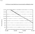
- FIG. 3 is a graph illustrating the changes in cuff pressure in Example 1.
- the cuff 11 is wrapped around an arm, wrist, finger, etc.
- the pressure inside this cuff 11 is raised to a specific level by the pressure application means 12, after which it is reduced substantially linearly by the low-speed exhaust means 13 at a rate of 3 to 5 mm Hg/second.
- the pulse wave amplitude component is superposed over the cuff pressure during the course of this depressurization.
- the vascular viscoelasticity evaluation device 100 computes an index for vascular viscoelasticity will now be described more concretely.
- a measurement start switch provided to the interface 50 is turned on, which pressurizes the cuff 11 with the pressure application means 12 until the pressure required for blood pressure measurement is reached, then the pressure application is halted, and the low-speed exhaust means 13 next gradually exhausts the air inside the cuff 11, so that the pressure displacement brought about by the pulse wave component thereby begins to be transmitted to the cuff.
- the pressure detecting means 14 converts the cuff pressure into an electrical signal as a change in frequency, and the sampling means 15 samples at regular time intervals (for example, every 5 ms) and outputs a pulse in response to the sampled cuff pressure.
- FIG. 4 is a detailed view of the relation between the cuff pressure change and the amplitude value (dP/dt).
- FIG. 5 is a detailed view of a differential pulse wave near the systolic blood pressure in Example 1.
- a differential pulse wave can be obtained as shown in FIG. 4 .
- the positive amplitude peak value Vf1 that occurs first is the value of the peak out of the differential waveform within one pulse wave and out of the amplitude values in the positive direction relative to zero.
- the negative amplitude peak value Vr2 that occurs second is the value of the peak that occurs second out of this differential waveform within one pulse wave and out of the amplitude values in the negative direction relative to zero.
- a temporal differential pulse wave is a value indicative of the rate at which the volume of a blood vessel changes.
- a positive amplitude value indicates the dilation rate of the blood vessel, and a negative amplitude value indicates the contraction rate of the blood vessel.
- FIG. 6 is a detailed view of one pulse of a differential pulse waveform.
- the detailed view of the one-pulse differential waveform of FIG. 6 is a further enlargement of FIG. 5 , focusing on the temporal differential pulse wave within one pulse.
- the differential pulse wave within one pulse includes the positive amplitude peak value Vf1 that occurs first, the positive amplitude peak value Vf2 that occurs second, the negative amplitude peak value Vr1 that occurs first, and the negative amplitude peak value Vr2 that occurs second.
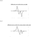
- FIG. 7 shows one pulse of a differential pulse waveform from a young person.
- FIG. 8 shows a differential pulse waveform from an elderly person and a patient with arterial sclerosis.
- the negative amplitude peak value Vr2 that occurs second is relatively greater than the other peak values, depending on age and vascular viscoelasticity. Therefore, vascular viscoelasticity can be evaluated on the basis of the ratio RT of the positive amplitude peak value Vf1 that occurs first to the negative amplitude peak value Vr2 that occurs second. In other words, vascular viscoelasticity can be properly evaluated by using the ratio RT between the positive amplitude peak value Vf1 that occurs first and the negative amplitude peak value Vr2 that occurs second.
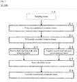
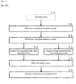
- FIG. 9 is a flowchart of the operation in Example 1.
- the cuff 11 is wrapped around the arm, wrist, finger, thigh, ankle, etc., of a measurement subject to obtain a pulse wave.
- the specific pressure required for blood pressure measurement is applied to the cuff 11 via the pressure application means 12.
- the pressure inside the cuff 11 applied by the pressure application means 12 is gradually released by the low-speed exhaust means 13.
- the pressure detecting means 14 converts the pressure of the cuff 11 into an electrical signal (pulse) and outputs the result.
- the sampling means 15 counts the number of electrical signals (pulses) from the pressure detecting means 14 within a specific length of time, repeats this count periodically in response to a sampling signal, and subjects the sampled value to A/D conversion.
- the pulse wave component extraction means 21 extracts the pulse wave component of the cuff pressure.
- the differential waveform formation means 22 subjects the extracted pulse wave component to temporal differentiation to calculate a primary differential value and form a differential waveform.
- the positive first amplitude peak value detecting means 23 detects the positive amplitude peak value Vf1 that occurs first within one pulse wave of the differential waveform in a state that an external force substantially the same as or greater than the systolic blood pressure has been exerted on a blood vessel.
- the negative second amplitude peak value detecting means 24 detects the negative amplitude peak value Vr2 that occurs second in the pulse wave in which the positive amplitude peak value Vf1 that occurs first has been detected.
- the ratio calculation means 25 calculates the ratio RT of the positive amplitude peak value Vf1 that occurs first with reference to the negative amplitude peak value Vr2 that occurs second.
- the vascular viscoelasticity evaluation means 26 evaluates vascular viscoelasticity on the basis of the ratio RT calculated by the ratio calculation means 25.
- Example 1 reliability in the evaluation of vascular viscoelasticity is high when a pulse wave is measured with a single cuff and a determination index for vascular viscoelasticity is calculated on the basis of this measured pulse wave, and when the determination index for vascular viscoelasticity is calculated for a measurement subject that is a relatively young person.
- a difference can be used instead of using a ratio.
- the vascular viscoelasticity can be evaluated on the basis of the difference between the positive amplitude peak value Vf1 that occurs first and the negative amplitude peak value Vr2 that occurs second.
- FIG. 10 is a block diagram of a vascular viscoelasticity evaluation device 200 in Example 2 of the present invention.
- the vascular viscoelasticity evaluation device 200 is an example of detecting the positive amplitude peak value Vf1 that occurs first and the negative amplitude peak value Vr2 that occurs second in a state in which a negative amplitude peak has been substantially reached.
- the positive amplitude peak value Vf1 that occurs first and the negative amplitude peak value Vr2 that occurs second are detected, while in the vascular viscoelasticity evaluation device 100 they are detected in a state that an external force substantially the same as or greater than the systolic blood pressure has been exerted on the blood vessel, in the vascular viscoelasticity evaluation device 200, such values are detected in a state in which a negative amplitude peak has been substantially reached.
- the vascular viscoelasticity evaluation device 200 is the same as the vascular viscoelasticity evaluation device 100, except that a CPU 20a is provided in place of the CPU 20.
- FIG. 11 is a diagram illustrating the configuration of the CPU 20a of Example 2.
- a positive first amplitude peak value detecting means 73 is provided in place of the positive first amplitude peak value detecting means 23 of CPU20, and a negative second amplitude peak value detecting means 74 is provided in place of the negative second amplitude peak value detecting means 24 of CPU 20.
- the positive first amplitude peak value detecting means 73 detects the positive amplitude peak value Vf1 that occurs first within one pulse wave of the differential waveform described above in a state in which a negative amplitude peak has been substantially reached.
- the negative second amplitude peak value detecting means 74 detects the negative amplitude peak value Vr2 that occurs second within one pulse wave of the above-described differential waveform in a state in which the negative amplitude peak has been substantially reached. In other words, the negative second amplitude peak value detecting means 74 detects the negative amplitude peak value Vr2 that occurs second in the pulse wave in which the above-described positive amplitude peak value Vf1 that occurs first has been detected.
- Example 2 reliability in the evaluation of vascular viscoelasticity is high when a pulse wave is measured with a single cuff and a determination index for vascular viscoelasticity is calculated on the basis of this measured pulse wave, and when the determination index for vascular viscoelasticity is calculated for a measurement subject that is a relatively young person.
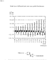
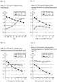
- FIG. 12 is a graph illustrating characteristics of the ratio RT (Vr2/Vf1), Vr1/Vf1 with reference to age in Example 2.
- Vr2/Vr1 reflects the viscoelasticity of a central artery and is an index that is not greatly affected by the hardness of brachial blood vessels.
- the vascular viscoelasticity evaluation means 26 evaluates vascular viscoelasticity on the basis of the ratio RT (Vr2/Vf1) calculated by the ratio calculation means 25.
- ratio RT Vr2/Vf1
- average values for the ratio RT (Vr2/Vr1) with respect to age, sex, etc. are entered in a table in advance, and the risk of arteriosclerosis is determined by comparing these averages.
- FIG. 13 is a graph illustrating characteristics of the ratio RT, Vr1/Vf1 of the hardness of brachial blood vessels at age 25.
- FIG. 14 is a graph illustrating characteristics of the ratio RT, Vr1/Vf1 of the hardness of brachial blood vessels at age 55.
- FIG. 15 is a graph illustrating characteristics of the ratio RT, Vr1/Vf1 of the hardness of brachial blood vessels at age 85.
- Vr1/Vf1 the curve plotted with black circles
- Vr1/Vf1 the curve plotted with black circles
- RT the ratio RT
- Vr2/Vf1 the curve plotted with white circles
- the cuff pressure is gradually reduced; however, the Examples are applicable also to a case in which the cuff pressure is gradually raised.
- a difference can be used instead of using a ratio.
- the positive amplitude peak value Vf1 that occurs first and the negative amplitude peak value Vr2 that occurs second are detected in a state in which a negative amplitude peak has been substantially reached, and then the vascular viscoelasticity is evaluated on the basis of the difference between the positive amplitude peak value Vf1 that occurs first and the negative amplitude peak value Vf2 that occurs second.
- FIG. 16 is a block diagram of a vascular viscoelasticity evaluation device 300 of Example 3 of the present invention.
- the vascular viscoelasticity evaluation device 300 is an Example, in which a pressure that is 40 mm Hg higher than the cuff pressure during measurement of the systolic blood pressure which is obtained by the vascular viscoelasticity evaluation device 100 is maintained for about 22 seconds, and the positive amplitude peak value Vf1 that occurs first and the negative amplitude peak value Vr2 that occurs second are detected within one pulse wave of a differential waveform obtained by the temporal differentiation of the pulse wave component extracted while this cuff pressure was being maintained.
- the vascular viscoelasticity evaluation device 300 comprises the cuff 11, the pressure application means 12, the low-speed exhaust means 13, the pressure detecting means 14, the sampling means 15, a CPU 20b, the ROM 30, the RAM 40, the interface 50, the display device 61, the printer 62, and the external terminal 63.
- FIG. 17 is a block diagram showing the function of the CPU 20b.
- the CPU 20b controls the entire vascular viscoelasticity evaluation device 300, and functionally, it works in conjunction with programs stored in the ROM 30 ( FIG. 18 shows a corresponding flowchart) to form implementation of the pulse wave component extraction means 21, the differential waveform formation means 22, a positive first amplitude peak value detecting means 83, a negative second amplitude peak value detecting means 84, the ratio calculation means 25, and the vascular viscoelasticity evaluation means 26.
- the pulse wave component extraction means 21 extracts the pulse wave component of the cuff pressure.
- the differential waveform formation means 22 subjects the pulse wave component extracted by the pulse wave component extraction means 21 to temporal differentiation to calculate a primary differential value and form a differential waveform.
- the positive first amplitude peak value detecting means 83 maintains the pressure 40 mm Hg higher than the cuff pressure which is at the time of measurement of the systolic blood pressure for 22 seconds, and it detects the positive amplitude peak value Vf1 that occurs first within one pulse wave of a differential waveform obtained by the temporal differentiation of a pulse wave component extracted while the cuff pressure is being maintained.
- the negative second amplitude peak value detecting means 84 detects the negative amplitude peak value Vr2 that occurs second in the pulse wave in which the positive amplitude peak value Vf1 that occurs first was detected.
- the ratio calculation means 25 calculates the ratio RT (Vr2/Vf1) of the positive amplitude peak value Vf1 that occurs first and the negative amplitude peak value Vf2 that occurs second.
- the vascular viscoelasticity evaluation means 26 evaluates vascular viscoelasticity on the basis of the ratio RT calculated by the ratio calculation means 25.
- FIG. 18 is a flowchart of the operation in Example 3.
- the cuff 11 is wrapped around the arm, wrist, finger, thigh, ankle, etc., of a measurement subject to obtain a pulse wave.
- ordinary blood pressure measurement is performed to measure the systolic blood pressure.
- a pressure that is 40 mm Hg higher than the cuff pressure when the systolic blood pressure was measured is maintained for 22 seconds, and in S4 the pressure detecting means 14 converts the pressure of the cuff 11 into an electrical signal (pulse) and outputs the result.
- the sampling means 15 counts the number of electrical signals (pulses) from the pressure detecting means 14 within a specific length of time, repeats this count periodically in response to a sampling signal and subjects the sampled value to A/D conversion.
- the pulse wave component extraction means 21 extracts the pulse wave component of the cuff pressure.
- the differential waveform formation means 22 subjects the extracted pulse wave component to temporal differentiation to calculate a primary differential value and form a differential waveform.
- the positive first amplitude peak value detecting means 83 detects the positive amplitude peak value Vf1 that occurs first within one pulse wave of the differential waveform described above.
- the negative second amplitude peak value detecting means 84 detects the negative amplitude peak value Vr2 that occurs second.
- the ratio calculation means 25 calculates the ratio RT of the positive amplitude peak value Vf1 that occurs first to the negative amplitude peak value Vf2 that occurs second.
- the vascular viscoelasticity evaluation means 26 evaluates vascular viscoelasticity on the basis of the ratio RT calculated by the ratio calculation means 25. Then, in S12, the pressure inside the cuff 11 applied by the pressure application means 12 is gradually released by the low-speed exhaust means 13.
- FIG. 19 is a graph of the relation between the pressure applied to the cuff and the cuff oscillation pressure measured at the cuff in Example 3.
- the pressure applied to the cuff which is indicated by a solid line (the oscillation pressure measured at the cuff), rises sharply to 160 mm Hg six (6) to eight (8) seconds after the start of measurement.
- This value of 160 mm Hg is a pressure obtained by adding 40 mm Hg to the systolic blood pressure.
- the broken line indicates blood pressure directly under the cuff, and the one-dot chain line indicates the pressure applied to the cuff.
- Example 3 a pressure that is 40 mm Hg higher than the cuff pressure during measurement of the systolic blood pressure is maintained for 22 seconds, and the positive amplitude peak value that occurs first and the negative amplitude peak value that occurs second within one pulse wave of a differential waveform obtained by the temporal differentiation of an extracted pulse wave component are repeatedly detected while this cuff pressure 160 mm Hg is being maintained; accordingly, abnormal values can be detected and eliminated.
- a pressure that is 40 mm Hg higher than the cuff pressure at which the systolic blood pressure occurred is set, and this cuff pressure is maintained for 22 seconds.
- a pressure obtained by adding 30 to 50 mm Hg to the cuff pressure at which the systolic blood pressure occurred can be used instead as the cuff pressure.
- the cuff pressure it is preferable to set the cuff pressure to be a pressure obtained by adding 30 to 50 mm Hg to the cuff pressure at which the systolic blood pressure occurred.
- the state in which the pressure is set higher than the systolic blood pressure may be maintained for some length of time other than 22 seconds, such as 5 to 30 seconds. More specifically, if measurement is obtained while a state in which the pressure is set higher than the systolic blood pressure is sustained for a length of time shorter than 5 seconds, stability of the measured values is unable to obtain; and on the other hand, if measurement is obtained while the state in which the pressure is set higher than the systolic blood pressure is sustained for a length of time longer than 30 seconds, then blood congestion oscillation pressure occur, the characteristics of the blood vessel will change, and the reliability of the measured values will suffer. Accordingly, it is preferable that the state in which the pressure is set higher than the systolic blood pressure be sustained for a period of time between 5 and 30 seconds.
- a difference can be used instead of using a ratio.
- the vascular viscoelasticity can be evaluated on the basis of the difference between the positive amplitude peak value Vf1 that occurs first and the negative amplitude peak value Vr2 that occurs second, which are both detected within one pulse wave of the above-described differential pulse wave obtained by the temporal differentiation of a pulse wave component extracted while a cuff pressure that is higher by a specific amount than the cuff pressure at which the systolic blood pressure occurred is being maintained for a specific length of time by the cuff pressure maintenance means.
- the present invention can be used in applications that require high reliability in the evaluation of arterial sclerosis when a pulse wave is measured with a single cuff and a determination index for arterial sclerosis is calculated on the basis of this measured pulse wave and when arterial sclerosis is evaluated for a measurement subject that is a relatively young person.
- the present invention can be used in applications that require high reliability in the evaluation of arterial sclerosis when a pulse wave is measured with a single cuff and a determination index for arterial sclerosis is calculated on the basis of this measured pulse wave and when evaluating arterial sclerosis wherein the measurement subject is a relatively young person.
Landscapes
- Health & Medical Sciences (AREA)
- Life Sciences & Earth Sciences (AREA)
- Engineering & Computer Science (AREA)
- Cardiology (AREA)
- Physiology (AREA)
- Public Health (AREA)
- Molecular Biology (AREA)
- Physics & Mathematics (AREA)
- Veterinary Medicine (AREA)
- Biophysics (AREA)
- Pathology (AREA)
- Biomedical Technology (AREA)
- Heart & Thoracic Surgery (AREA)
- Medical Informatics (AREA)
- General Health & Medical Sciences (AREA)
- Surgery (AREA)
- Animal Behavior & Ethology (AREA)
- Vascular Medicine (AREA)
- Signal Processing (AREA)
- Computer Vision & Pattern Recognition (AREA)
- Psychiatry (AREA)
- Artificial Intelligence (AREA)
- Ophthalmology & Optometry (AREA)
- Pulmonology (AREA)
- Measuring Pulse, Heart Rate, Blood Pressure Or Blood Flow (AREA)
Description
- The present invention relates to a device, method, and program for non-invasively evaluating the degree of vascular viscoelasticity by analyzing pulse waves.
- Pulse wave propagation velocity (PWV) has been a widespread device for evaluating vascular viscoelasticity non-invasively up to now. In this method, pulse waves must be measured using a cuff or the like attached at two or more places.
- Meanwhile, there are known devices for evaluating vascular viscoelasticity by pulse wave measurement with a cuff attached at only one place, in which the pulse wave component of the cuff pressure is extracted, this extracted pulse wave component is subjected to temporal differentiation to calculate a primary differential value and form a differential waveform, and in a state in which an external force substantially the same as or greater than the systolic blood pressure is being exerted on the blood vessel, the positive amplitude peak value within one pulse wave of the differential waveform is detected, the negative amplitude peak value is detected in a pulse wave in which the positive amplitude peak value was detected, the ratio of the peak value of the positive amplitude to the peak value of the negative amplitude is calculated, and then the vascular viscoelasticity is evaluated on the basis of this calculated ratio (
Japanese Patent No.: 4,054,884 -
WO 2010/058484 A1 discloses a device for evaluating vascular viscoelasticity. - CONG LUO ET AL: "Measurement and clinical study of arterial compliance",AUTOMATION CONGRESS, 2008. WAC 2008. WORLD, IEEE, PISCATAWAY, NJ, USA, 28 September 2008 (2008-09-28), pages 1-4, ISBN: 978-1-889335-38-4, discloses measurements of arterial compliance.
- Within one pulse wave of the differentiated waveform of a relatively young person, of the negative amplitude peaks, the first peak value that occurs is usually the maximum peak value. When pulse waves are measured for this relatively young person using the device disclosed in
Patent Reference 1, since the above-described maximum peak value is used as data for evaluating vascular viscoelasticity, a problem is that reliability of the evaluation of the vascular viscoelasticity is low. - It is an object of the present invention to provide a vascular viscoelasticity evaluation device, a vascular viscoelasticity evaluation method, and a program with which vascular viscoelasticity can be evaluated with high reliability when a pulse wave is measured with a single cuff, and a determination index for vascular viscoelasticity is calculated on the basis of this measured pulse wave, and when calculating the determination index for vascular viscoelasticity wherein the measurement subject is a relatively young person.
- The viscoelasticity of a blood vessel has been shown to be associated with atherosclerosis, and the risk of arteriosclerosis rises in proportion to the hardness of a blood vessel. In particular, the viscoelasticity of the blood vessels of a central artery is held to have great clinical significance, and being able to accurately evaluate the viscoelasticity of a central artery with a single cuff has considerable importance from a societal perspective.
- The invention is defined by a device according to
independent claim 1, a method according toindependent claim 6 and a computer program product according toindependent claim 9. Embodiments are defined by claims 2-5 and 7-8. - Within one pulse wave of a differential waveform obtained by temporal differentiation of a pulse wave component extracted in a state that an external force that is substantially the same as or greater than the systolic blood pressure has been exerted on a blood vessel, a positive amplitude peak value Vf1 that occurs first and a peak Vr2 that occurs second out of a plurality of negative amplitude peak values are detected, a ratio of the positive amplitude peak value Vf1 that occurs first with respect to the negative amplitude peak value Vr2 that occurs second is calculated, and vascular viscoelasticity is evaluated on the basis of this calculated ratio.
- According to the present invention such an effect is provided that vascular viscoelasticity can be evaluated with high reliability when a pulse wave is measured with a single cuff, and a determination index for vascular viscoelasticity is calculated on the basis of this measured pulse wave, and when the determination index for vascular viscoelasticity is calculated with the measurement subject being a relatively young person.
- Also, since the evaluation is made on the basis of the above-described calculated ratio, the viscoelasticity of a central artery can be accurately evaluated without being affected by the hardness of brachial blood vessels.
-
-
FIG. 1 is a block diagram of a vascularviscoelasticity evaluation device 100 of Example 1 of the present invention; -
FIG. 2 is a block diagram illustrating the functions of aCPU 20; -
FIG. 3 is a graph of changes in cuff pressure in Example 1; -
FIG. 4 is a detailed view of a relation (dP/dt) between the change in cuff pressure and the amplitude value; -
FIG. 5 is a detailed view of a differential pulse wave near the systolic blood pressure in Example 1; -
FIG. 6 is a detailed view of one pulse of a differential pulse waveform; -
FIG. 7 shows one pulse of a differential pulse waveform from a young person; -
FIG. 8 shows a differential pulse waveform from an elderly person and a patient with arterial sclerosis; -
FIG. 9 is a flowchart of the operation in Example 1; -
FIG. 10 is a block diagram of a vascularviscoelasticity evaluation device 200 according to Example 2; -
FIG. 11 is a diagram of the configuration of aCPU 20a in Example 2; -
FIG. 12 a graph illustrating characteristics of a ratio RT (Vr2/Vf1), Vr1/Vf1 with reference to age in Example 2; -
FIG. 13 is a graph illustrating characteristics of a ratio RT, Vr1/Vf1 of the hardness of brachial blood vessels atage 25 in Example 2; -
FIG. 14 is a graph illustrating characteristics of a ratio RT, Vr1/Vf1 of the hardness of brachial blood vessels at age 55 in Example 2; -
FIG. 15 is a graph illustrating characteristics of a ratio RT, Vr1/Vf1 of the hardness of brachial blood vessels atage 85; -
FIG. 16 is a block diagram of a vascularviscoelasticity evaluation device 300 in Example 3; -
FIG. 17 is a block diagram of the function of aCPU 20b; -
FIG. 18 is a flowchart of the operation in Example 3; and -
FIG. 19 is a graph of the relation between the pressure applied to the cuff and the cuff oscillation pressure measured at the cuff in Example 3. - Examples of the invention are presented below by the following Examples.
-
FIG. 1 is a block diagram of a vascularviscoelasticity evaluation device 100 of Example 1 of the present invention. The vascularviscoelasticity evaluation device 100 is comprised of acuff 11, a pressure application means 12, a low-speed exhaust means 13, a pressure detecting means 14, a sampling means 15, aCPU 20, aROM 30, aRAM 40, aninterface 50, adisplay device 61, aprinter 62, and anexternal terminal 63. - The
cuff 11, the pressure application means 12, the low-speed exhaust means 13, and the pressure detecting means 14 are connected by flexible tubing. Also, the pressure application means 12, the low-speed exhaust means 13, the pressure detecting means 14, and the sampling means 15 are controlled by theCPU 20. - The
cuff 11 is wrapped around the arm, wrist, finger, thigh, ankle, etc., of a measurement subject to obtain a pulse wave. The pressure application means 12 pressurizes thecuff 11 to a predetermined pressure needed for blood pressure measurement. The low-speed exhaust means 13 gradually releases the pressure inside thecuff 11 pressurized by the pressure application means 12. - The pressure detecting means 14 includes a pressure transducer for detecting the pressure of the
cuff 11, and it converts the above-described pressure into an electrical signal (pulse) and outputs the result. The sampling means 15 counts the number of electrical signals (pulses) from the pressure detecting means 14 within a specific length of time, and it repeats this count periodically in response to a sampling signal, and further subjects the sampled value to A/D conversion. -
FIG. 2 is a block diagram illustrating the function of theCPU 20. - The
CPU 20 controls the entire vascularviscoelasticity evaluation device 100, and functionally, it works in conjunction with programs stored in the ROM 30 (a corresponding flowchart is shown inFIG. 9 ) to form implementation of a pulse wave component extraction means 21, a differential waveform formation means 22, a positive first amplitude peak value detecting means 23, a negative second amplitude peak value detecting means 24, a ratio calculation means 25, and a vascular viscoelasticity evaluation means 26. - The pulse wave component extraction means 21 extracts the pulse wave component of the cuff pressure. The differential waveform formation means 22 subjects the pulse wave component extracted by the pulse wave component extraction means 21 to temporal differentiation to calculate a primary differential value and form a differential waveform.
- In a state in which an external force substantially the same as the systolic blood pressure has been exerted on a blood vessel, the positive first amplitude peak value detecting means 23 detects the positive amplitude peak value Vf1 that occurs first within one pulse wave of the above-described differential waveform.
- The negative second amplitude peak value detecting means 24 detects the negative amplitude peak value Vr2 that occurs second in the pulse wave in which the positive amplitude peak value Vf1 that occurs first was detected. The ratio calculation means 25 calculates the ratio RT (Vr2/Vf1) of the positive amplitude peak value Vf1 that occurs first with respect to the negative amplitude peak value Vr2 that occurs second. The vascular viscoelasticity evaluation means 26 evaluates vascular viscoelasticity on the basis of the ratio RT calculated by the ratio calculation means 25.
-
FIG. 3 is a graph illustrating the changes in cuff pressure in Example 1. - The
cuff 11 is wrapped around an arm, wrist, finger, etc. The pressure inside thiscuff 11 is raised to a specific level by the pressure application means 12, after which it is reduced substantially linearly by the low-speed exhaust means 13 at a rate of 3 to 5 mm Hg/second. The pulse wave amplitude component is superposed over the cuff pressure during the course of this depressurization. - How the vascular
viscoelasticity evaluation device 100 computes an index for vascular viscoelasticity will now be described more concretely. First, thecuff 11 is wrapped around the arm of a measurement subject, a measurement start switch provided to theinterface 50 is turned on, which pressurizes thecuff 11 with the pressure application means 12 until the pressure required for blood pressure measurement is reached, then the pressure application is halted, and the low-speed exhaust means 13 next gradually exhausts the air inside thecuff 11, so that the pressure displacement brought about by the pulse wave component thereby begins to be transmitted to the cuff. - The pressure detecting means 14 converts the cuff pressure into an electrical signal as a change in frequency, and the sampling means 15 samples at regular time intervals (for example, every 5 ms) and outputs a pulse in response to the sampled cuff pressure.
-
FIG. 4 is a detailed view of the relation between the cuff pressure change and the amplitude value (dP/dt). -
FIG. 5 is a detailed view of a differential pulse wave near the systolic blood pressure in Example 1. - When temporal differentiation is made for cuff pressure and the depressurization rate is removed from the cuff pressure, then a differential pulse wave can be obtained as shown in
FIG. 4 . InFIG. 4 , the positive amplitude peak value Vf1 that occurs first is the value of the peak out of the differential waveform within one pulse wave and out of the amplitude values in the positive direction relative to zero. Also, inFIG. 4 , the negative amplitude peak value Vr2 that occurs second is the value of the peak that occurs second out of this differential waveform within one pulse wave and out of the amplitude values in the negative direction relative to zero. - A temporal differential pulse wave is a value indicative of the rate at which the volume of a blood vessel changes. A positive amplitude value indicates the dilation rate of the blood vessel, and a negative amplitude value indicates the contraction rate of the blood vessel.
-
FIG. 6 is a detailed view of one pulse of a differential pulse waveform. - The detailed view of the one-pulse differential waveform of
FIG. 6 is a further enlargement ofFIG. 5 , focusing on the temporal differential pulse wave within one pulse. The differential pulse wave within one pulse includes the positive amplitude peak value Vf1 that occurs first, the positive amplitude peak value Vf2 that occurs second, the negative amplitude peak value Vr1 that occurs first, and the negative amplitude peak value Vr2 that occurs second. -
FIG. 7 shows one pulse of a differential pulse waveform from a young person. -
FIG. 8 shows a differential pulse waveform from an elderly person and a patient with arterial sclerosis. - As is clear from
FIGS. 7 and8 , the negative amplitude peak value Vr2 that occurs second is relatively greater than the other peak values, depending on age and vascular viscoelasticity. Therefore, vascular viscoelasticity can be evaluated on the basis of the ratio RT of the positive amplitude peak value Vf1 that occurs first to the negative amplitude peak value Vr2 that occurs second. In other words, vascular viscoelasticity can be properly evaluated by using the ratio RT between the positive amplitude peak value Vf1 that occurs first and the negative amplitude peak value Vr2 that occurs second. - Next, the operation in Example 1 will be described.
-
FIG. 9 is a flowchart of the operation in Example 1. - First, in S1, the
cuff 11 is wrapped around the arm, wrist, finger, thigh, ankle, etc., of a measurement subject to obtain a pulse wave. In S2, the specific pressure required for blood pressure measurement is applied to thecuff 11 via the pressure application means 12. In S3, the pressure inside thecuff 11 applied by the pressure application means 12 is gradually released by the low-speed exhaust means 13. - In S4, the pressure detecting means 14 converts the pressure of the
cuff 11 into an electrical signal (pulse) and outputs the result. In S5, the sampling means 15 counts the number of electrical signals (pulses) from the pressure detecting means 14 within a specific length of time, repeats this count periodically in response to a sampling signal, and subjects the sampled value to A/D conversion. - In S6, the pulse wave component extraction means 21 extracts the pulse wave component of the cuff pressure. In S7, the differential waveform formation means 22 subjects the extracted pulse wave component to temporal differentiation to calculate a primary differential value and form a differential waveform.
- In S8, the positive first amplitude peak
value detecting means 23 detects the positive amplitude peak value Vf1 that occurs first within one pulse wave of the differential waveform in a state that an external force substantially the same as or greater than the systolic blood pressure has been exerted on a blood vessel. In S9, the negative second amplitude peakvalue detecting means 24 detects the negative amplitude peak value Vr2 that occurs second in the pulse wave in which the positive amplitude peak value Vf1 that occurs first has been detected. - In S10, the ratio calculation means 25 calculates the ratio RT of the positive amplitude peak value Vf1 that occurs first with reference to the negative amplitude peak value Vr2 that occurs second. In S11, the vascular viscoelasticity evaluation means 26 evaluates vascular viscoelasticity on the basis of the ratio RT calculated by the ratio calculation means 25.
- In Example 1, reliability in the evaluation of vascular viscoelasticity is high when a pulse wave is measured with a single cuff and a determination index for vascular viscoelasticity is calculated on the basis of this measured pulse wave, and when the determination index for vascular viscoelasticity is calculated for a measurement subject that is a relatively young person.
- More specifically, when the hardness of a central artery in a human body is simulated on a computer and the parameters for hardening the central artery are controlled, this is reflected in the negative amplitude peak value Vr2 that occurs second. Therefore, by way of calculating the ratio RT of the positive amplitude peak value Vf1 that occurs first to the negative amplitude peak value Vr2 that occurs second and then evaluating vascular viscoelasticity on the basis of the ratio RT, it is possible to improve the reliability in the evaluation of vascular viscoelasticity for relatively young subjects.
- Also, in the above Example, a difference can be used instead of using a ratio. In other words, the vascular viscoelasticity can be evaluated on the basis of the difference between the positive amplitude peak value Vf1 that occurs first and the negative amplitude peak value Vr2 that occurs second.
-
FIG. 10 is a block diagram of a vascularviscoelasticity evaluation device 200 in Example 2 of the present invention. - The vascular
viscoelasticity evaluation device 200 is an example of detecting the positive amplitude peak value Vf1 that occurs first and the negative amplitude peak value Vr2 that occurs second in a state in which a negative amplitude peak has been substantially reached. - More specifically, when the positive amplitude peak value Vf1 that occurs first and the negative amplitude peak value Vr2 that occurs second are detected, while in the vascular
viscoelasticity evaluation device 100 they are detected in a state that an external force substantially the same as or greater than the systolic blood pressure has been exerted on the blood vessel, in the vascularviscoelasticity evaluation device 200, such values are detected in a state in which a negative amplitude peak has been substantially reached. - The vascular
viscoelasticity evaluation device 200 is the same as the vascularviscoelasticity evaluation device 100, except that aCPU 20a is provided in place of theCPU 20. -
FIG. 11 is a diagram illustrating the configuration of theCPU 20a of Example 2. - In the
CPU 20a, a positive first amplitude peakvalue detecting means 73 is provided in place of the positive first amplitude peak value detecting means 23 of CPU20, and a negative second amplitude peakvalue detecting means 74 is provided in place of the negative second amplitude peak value detecting means 24 ofCPU 20. - The positive first amplitude peak
value detecting means 73 detects the positive amplitude peak value Vf1 that occurs first within one pulse wave of the differential waveform described above in a state in which a negative amplitude peak has been substantially reached. - The negative second amplitude peak
value detecting means 74 detects the negative amplitude peak value Vr2 that occurs second within one pulse wave of the above-described differential waveform in a state in which the negative amplitude peak has been substantially reached. In other words, the negative second amplitude peakvalue detecting means 74 detects the negative amplitude peak value Vr2 that occurs second in the pulse wave in which the above-described positive amplitude peak value Vf1 that occurs first has been detected. - In Example 2, reliability in the evaluation of vascular viscoelasticity is high when a pulse wave is measured with a single cuff and a determination index for vascular viscoelasticity is calculated on the basis of this measured pulse wave, and when the determination index for vascular viscoelasticity is calculated for a measurement subject that is a relatively young person.
-
FIG. 12 is a graph illustrating characteristics of the ratio RT (Vr2/Vf1), Vr1/Vf1 with reference to age in Example 2. - It has been corroborated in a computer simulation performed by the Riken Institute of Physical and Chemical Research that the above-described Vr2/Vr1 reflects the viscoelasticity of a central artery and is an index that is not greatly affected by the hardness of brachial blood vessels.
- The vascular viscoelasticity evaluation means 26 evaluates vascular viscoelasticity on the basis of the ratio RT (Vr2/Vf1) calculated by the ratio calculation means 25. In this case, for example, average values for the ratio RT (Vr2/Vr1) with respect to age, sex, etc. are entered in a table in advance, and the risk of arteriosclerosis is determined by comparing these averages.
-
FIG. 13 is a graph illustrating characteristics of the ratio RT, Vr1/Vf1 of the hardness of brachial blood vessels atage 25. -
FIG. 14 is a graph illustrating characteristics of the ratio RT, Vr1/Vf1 of the hardness of brachial blood vessels at age 55. -
FIG. 15 is a graph illustrating characteristics of the ratio RT, Vr1/Vf1 of the hardness of brachial blood vessels atage 85. - As seen from
FIGS. 13 to 15 , in a conventional method involving Vr1/Vf1 (the curve plotted with black circles), when there is a change in the hardness of brachial blood vessels, Vr1/Vf1 changes; in other words, Vr1/Vf1 is affected by the hardness of brachial blood vessels. However, in the ratio RT (Vr2/Vf1; the curve plotted with white circles), when the hardness of brachial blood vessels changes, there is almost no change in the ratio RT (Vr2/Vf1); in other words, the ratio RT (Vr2/Vf1) is able to evaluate the hardness of a central artery without being affected by the hardness of brachial blood vessels. - In the Examples described above, the cuff pressure is gradually reduced; however, the Examples are applicable also to a case in which the cuff pressure is gradually raised.
- In addition, in the vascular
viscoelasticity evaluation device 200, a difference can be used instead of using a ratio. In other words, it is possible that the positive amplitude peak value Vf1 that occurs first and the negative amplitude peak value Vr2 that occurs second are detected in a state in which a negative amplitude peak has been substantially reached, and then the vascular viscoelasticity is evaluated on the basis of the difference between the positive amplitude peak value Vf1 that occurs first and the negative amplitude peak value Vf2 that occurs second. -
FIG. 16 is a block diagram of a vascularviscoelasticity evaluation device 300 of Example 3 of the present invention. - The vascular
viscoelasticity evaluation device 300 is an Example, in which a pressure that is 40 mm Hg higher than the cuff pressure during measurement of the systolic blood pressure which is obtained by the vascularviscoelasticity evaluation device 100 is maintained for about 22 seconds, and the positive amplitude peak value Vf1 that occurs first and the negative amplitude peak value Vr2 that occurs second are detected within one pulse wave of a differential waveform obtained by the temporal differentiation of the pulse wave component extracted while this cuff pressure was being maintained. - The vascular
viscoelasticity evaluation device 300 comprises thecuff 11, the pressure application means 12, the low-speed exhaust means 13, thepressure detecting means 14, the sampling means 15, aCPU 20b, theROM 30, theRAM 40, theinterface 50, thedisplay device 61, theprinter 62, and theexternal terminal 63. -
FIG. 17 is a block diagram showing the function of theCPU 20b. - The
CPU 20b controls the entire vascularviscoelasticity evaluation device 300, and functionally, it works in conjunction with programs stored in the ROM 30 (FIG. 18 shows a corresponding flowchart) to form implementation of the pulse wave component extraction means 21, the differential waveform formation means 22, a positive first amplitude peakvalue detecting means 83, a negative second amplitude peakvalue detecting means 84, the ratio calculation means 25, and the vascular viscoelasticity evaluation means 26. - The pulse wave component extraction means 21 extracts the pulse wave component of the cuff pressure. The differential waveform formation means 22 subjects the pulse wave component extracted by the pulse wave component extraction means 21 to temporal differentiation to calculate a primary differential value and form a differential waveform.
- The positive first amplitude peak
value detecting means 83 maintains thepressure 40 mm Hg higher than the cuff pressure which is at the time of measurement of the systolic blood pressure for 22 seconds, and it detects the positive amplitude peak value Vf1 that occurs first within one pulse wave of a differential waveform obtained by the temporal differentiation of a pulse wave component extracted while the cuff pressure is being maintained. The negative second amplitude peakvalue detecting means 84 detects the negative amplitude peak value Vr2 that occurs second in the pulse wave in which the positive amplitude peak value Vf1 that occurs first was detected. The ratio calculation means 25 calculates the ratio RT (Vr2/Vf1) of the positive amplitude peak value Vf1 that occurs first and the negative amplitude peak value Vf2 that occurs second. The vascular viscoelasticity evaluation means 26 evaluates vascular viscoelasticity on the basis of the ratio RT calculated by the ratio calculation means 25. - Next, the operation of Example 3 will be described.
-
FIG. 18 is a flowchart of the operation in Example 3. - First, in S1, the
cuff 11 is wrapped around the arm, wrist, finger, thigh, ankle, etc., of a measurement subject to obtain a pulse wave. In S20, ordinary blood pressure measurement is performed to measure the systolic blood pressure. Then, in S21, a pressure that is 40 mm Hg higher than the cuff pressure when the systolic blood pressure was measured is maintained for 22 seconds, and in S4 the pressure detecting means 14 converts the pressure of thecuff 11 into an electrical signal (pulse) and outputs the result. In S5, the sampling means 15 counts the number of electrical signals (pulses) from the pressure detecting means 14 within a specific length of time, repeats this count periodically in response to a sampling signal and subjects the sampled value to A/D conversion. In S6, the pulse wave component extraction means 21 extracts the pulse wave component of the cuff pressure. In S7, the differential waveform formation means 22 subjects the extracted pulse wave component to temporal differentiation to calculate a primary differential value and form a differential waveform. - In S28, the positive first amplitude peak
value detecting means 83 detects the positive amplitude peak value Vf1 that occurs first within one pulse wave of the differential waveform described above. In S29, the negative second amplitude peakvalue detecting means 84 detects the negative amplitude peak value Vr2 that occurs second. In S10, the ratio calculation means 25 calculates the ratio RT of the positive amplitude peak value Vf1 that occurs first to the negative amplitude peak value Vf2 that occurs second. In S11, the vascular viscoelasticity evaluation means 26 evaluates vascular viscoelasticity on the basis of the ratio RT calculated by the ratio calculation means 25. Then, in S12, the pressure inside thecuff 11 applied by the pressure application means 12 is gradually released by the low-speed exhaust means 13. -
FIG. 19 is a graph of the relation between the pressure applied to the cuff and the cuff oscillation pressure measured at the cuff in Example 3. - As seen from
FIG. 19 , the pressure applied to the cuff, which is indicated by a solid line (the oscillation pressure measured at the cuff), rises sharply to 160 mm Hg six (6) to eight (8) seconds after the start of measurement. This value of 160 mm Hg is a pressure obtained by adding 40 mm Hg to the systolic blood pressure. Once the cuff pressure reaches 160 mm Hg, it is maintained there for 22 seconds. Consequently, the transient pressure fluctuation component gradually disappears 14 seconds after the start of measurement, and the oscillation pressure measured at the cuff (the pressure indicated by the solid line) stabilizes in a state ofequilibrium 20 seconds after the start of measurement. By way of maintaining this state for a specific length of time, it is possible that a plurality of pulse waves are extracted stably. Accordingly, it becomes easier to detect and eliminate body motion noise and the like that occur during measurement, and the peak value of a differential pulse wave can be detected more accurately. - In
FIG. 19 , the broken line indicates blood pressure directly under the cuff, and the one-dot chain line indicates the pressure applied to the cuff. - More specifically, in Example 3, a pressure that is 40 mm Hg higher than the cuff pressure during measurement of the systolic blood pressure is maintained for 22 seconds, and the positive amplitude peak value that occurs first and the negative amplitude peak value that occurs second within one pulse wave of a differential waveform obtained by the temporal differentiation of an extracted pulse wave component are repeatedly detected while this
cuff pressure 160 mm Hg is being maintained; accordingly, abnormal values can be detected and eliminated. In addition, in the above Example, a pressure that is 40 mm Hg higher than the cuff pressure at which the systolic blood pressure occurred is set, and this cuff pressure is maintained for 22 seconds. However, a pressure obtained by adding 30 to 50 mm Hg to the cuff pressure at which the systolic blood pressure occurred can be used instead as the cuff pressure. In other words, if measurement is performed by applying a pressure that is lower than 30 mm Hg to the cuff pressure at which the systolic blood pressure occurred, blood will start to flow to the blood vessel, and it will become difficult to eliminate body motion noise and the like that occur during measurement. On the other hand, if measurement is performed by applying a pressure that is higher than 50 mm Hg to the cuff pressure at which the systolic blood pressure occurred, the measurement subject may experience pain caused by this pressure. Therefore, it is preferable to set the cuff pressure to be a pressure obtained by adding 30 to 50 mm Hg to the cuff pressure at which the systolic blood pressure occurred. - Furthermore, the state in which the pressure is set higher than the systolic blood pressure may be maintained for some length of time other than 22 seconds, such as 5 to 30 seconds. More specifically, if measurement is obtained while a state in which the pressure is set higher than the systolic blood pressure is sustained for a length of time shorter than 5 seconds, stability of the measured values is unable to obtain; and on the other hand, if measurement is obtained while the state in which the pressure is set higher than the systolic blood pressure is sustained for a length of time longer than 30 seconds, then blood congestion oscillation pressure occur, the characteristics of the blood vessel will change, and the reliability of the measured values will suffer. Accordingly, it is preferable that the state in which the pressure is set higher than the systolic blood pressure be sustained for a period of time between 5 and 30 seconds.
- In other word, what should be done is to extract the above-described differential waveform obtained by the temporal differentiation of a pulse wave component while a cuff pressure that is higher by a specific amount than the cuff pressure at which the systolic blood pressure occurred is being maintained for a specific length of time by a cuff pressure maintenance means, and then to detect the positive amplitude peak value Vf1 that occurs first within one pulse wave of the above-described differential pulse wave obtained by the temporal differentiation of the extracted pulse wave component.
- Furthermore, in the vascular
viscoelasticity evaluation device 300, a difference can be used instead of using a ratio. In other words, the vascular viscoelasticity can be evaluated on the basis of the difference between the positive amplitude peak value Vf1 that occurs first and the negative amplitude peak value Vr2 that occurs second, which are both detected within one pulse wave of the above-described differential pulse wave obtained by the temporal differentiation of a pulse wave component extracted while a cuff pressure that is higher by a specific amount than the cuff pressure at which the systolic blood pressure occurred is being maintained for a specific length of time by the cuff pressure maintenance means. - In addition, if the various means described in the Examples above are substituted for steps, then the above Examples become examples of the vascular viscoelasticity evaluation method of the present invention. Furthermore, in the above Examples, hardware such as a circuit for implementing the functions of programs executed by a CPU can be provided instead of a CPU. Also, it is possible that part of the program is implemented with hardware, and the remaining portion is executed by a computer.
- The present invention can be used in applications that require high reliability in the evaluation of arterial sclerosis when a pulse wave is measured with a single cuff and a determination index for arterial sclerosis is calculated on the basis of this measured pulse wave and when arterial sclerosis is evaluated for a measurement subject that is a relatively young person.
- The present invention can be used in applications that require high reliability in the evaluation of arterial sclerosis when a pulse wave is measured with a single cuff and a determination index for arterial sclerosis is calculated on the basis of this measured pulse wave and when evaluating arterial sclerosis wherein the measurement subject is a relatively young person.
-
- 100, 200, 300 Vascular viscoelasticity evaluation device
- 11 Cuff
- 20, 20a CPU
- 21 Pulse wave component extraction means
- 22 Differential waveform formation means
- 23, 73, 83 Positive first amplitude peak value detecting means
- 24, 74, 84 Negative second amplitude peak value detecting means
- 25 Ratio calculation means
- 26 Vascular viscoelasticity evaluation means
Claims (9)
- A vascular viscoelasticity evaluation device (100) comprising:- a cuff (11) and pressure application means (12) to exert an external force substantially the same as or greater than systolic blood pressure on a blood vessel;- a pulse wave component extraction means (21) for extracting a pulse wave component of cuff pressure;- a differential waveform formation means (22) for subjecting the extracted pulse wave component to temporal differentiation to calculate a primary differential value and form a differential waveform;- a positive first amplitude peak value detecting means (23) for detecting a positive amplitude peak value that occurs first within one pulse wave of a differential waveform obtained by the temporal differentiation of a pulse wave component extracted in a state in which the external force has been exerted;wherein the device additionally comprises:- a negative second amplitude peak value detecting means (24) for detecting a plurality of negative amplitude peak values that occur in the pulse wave in which the positive amplitude peak value that occurs first was detected and for determining a negative amplitude peak value that occurs second among the plurality of negative amplitude peak values;- a calculation means (25) for calculating a ratio of the positive amplitude peak value that occurs first to the negative amplitude peak value that occurs second among the plurality of negative amplitude peak values, or for calculating a difference between the positive amplitude peak value that occurs first and the negative amplitude peak value that occurs second among the plurality of negative amplitude peak values; and- a vascular viscoelasticity evaluation means (26) for evaluating vascular viscoelasticity on a basis of the ratio calculated by the calculation means or on a basis of the difference calculated by the calculation means.
- A vascular viscoelasticity evaluation device (100) of claim 1, characterized in that- said differential waveform obtained by the temporal differentiation of a pulse wave component is additionally extracted in a state in which a negative amplitude peak has been substantially reached.
- A vascular viscoelasticity evaluation device (100) of claim 1 characterized in that the device additionally comprises:- a cuff pressure maintenance means for maintaining a cuff pressure for a specific length of time at a pressure that is higher by a specific amount than the cuff pressure when a systolic blood pressure is measured; whereupon- said differential waveform obtained by the temporal differentiation of a pulse wave component is extracted while the cuff pressure maintenance means is maintaining the cuff pressure for a specific length of time.
- The device according to claim 3, wherein the specific length of time is a time between 5 and 30 seconds.
- A vascular viscoelasticity evaluation device (100) of claim 1, characterized in that:
said calculation means (25) for calculating a ratio of the positive amplitude peak value that occurs first to the negative amplitude peak value that occurs second is a ratio calculation means (25), and for calculating a difference between the positive amplitude peak value that occurs first and the negative amplitude peak value that occurs second is a difference calculation means. - A vascular viscoelasticity evaluation method, comprising:- applying pressure to a cuff by pressure application means to exert an external force substantially the same as or greater than systolic blood pressure on a blood vessel;- a pulse wave component extraction step in which a pulse wave component extraction means extracts a pulse wave component of cuff pressure;- a differential waveform formation step in which a differential waveform formation means subjects the extracted pulse wave component to temporal differentiation to calculate a primary differential value and form a differential waveform;- a positive first amplitude peak value detecting step in which a positive first amplitude peak value detecting means detects a positive amplitude peak value that occurs first within one pulse wave of a differential waveform obtained by the temporal differentiation of a pulse wave component extracted in a state in which the external force has been exerted:- a negative second amplitude peak value detecting step in which a negative second amplitude peak value detecting means detects a plurality of negative amplitude peak values that occur in the pulse wave in which the positive amplitude peak value that occurs first was detected and detects a negative amplitude peak value that occurs second among the plurality of negative amplitude peak values;- a calculation step in which a calculation means calculates a ratio of the positive amplitude peak value that occurs first to the negative amplitude peak value that occurs second among the plurality of negative amplitude peak values, or calculates a difference between the positive amplitude peak value that occurs first and the negative amplitude peak value that occurs second among the plurality of negative amplitude peak values; and- a vascular viscoelasticity evaluation step in which a vascular viscoelasticity evaluation means evaluates vascular viscoelasticity on a basis of the ratio or difference calculated in the calculation step.
- A vascular viscoelasticity evaluation method of claim 6, characterized in that:- said differential waveform obtained by the temporal differentiation of a pulse wave component is additionally extracted in a state in which a negative amplitude peak has been substantially reached.
- A vascular viscoelasticity evaluation method of claim 6, characterized in that the method additionally comprises:- a cuff pressure maintenance step in which a cuff pressure maintenance means maintains the cuff pressure for a specific length of time at a pressure that is higher by a specific amount than cuff pressure when a systolic blood pressure is measured; whereupon- said differential waveform obtained by the temporal differentiation of said pulse wave component is additionally extracted while the cuff pressure maintenance means is maintaining the cuff pressure for a specific length of time.
- A computer program product comprising a computer program code means (20), which is configured to perform the steps of any of method claims 6-8, when said computer program code means is run on the vascular viscoelasticity evaluation device according to any one of claims 1-5.
Applications Claiming Priority (2)
| Application Number | Priority Date | Filing Date | Title |
|---|---|---|---|
| JP2013063787A JP6218267B2 (en) | 2013-03-26 | 2013-03-26 | Vascular viscoelasticity evaluation apparatus, vascular viscoelasticity evaluation method and program |
| PCT/JP2014/059385 WO2014157714A1 (en) | 2013-03-26 | 2014-03-24 | Vascular viscoelasticity evaluation device, vascular viscoelasticity evaluation method, and program |
Publications (3)
| Publication Number | Publication Date |
|---|---|
| EP2979628A1 EP2979628A1 (en) | 2016-02-03 |
| EP2979628A4 EP2979628A4 (en) | 2017-02-22 |
| EP2979628B1 true EP2979628B1 (en) | 2021-07-07 |
Family
ID=51624669
Family Applications (1)
| Application Number | Title | Priority Date | Filing Date |
|---|---|---|---|
| EP14774331.4A Active EP2979628B1 (en) | 2013-03-26 | 2014-03-24 | Vascular viscoelasticity evaluation device, vascular viscoelasticity evaluation method, and program |
Country Status (6)
| Country | Link |
|---|---|
| US (1) | US10506932B2 (en) |
| EP (1) | EP2979628B1 (en) |
| JP (1) | JP6218267B2 (en) |
| CN (1) | CN105358047B (en) |
| RU (1) | RU2676514C2 (en) |
| WO (1) | WO2014157714A1 (en) |
Families Citing this family (2)
| Publication number | Priority date | Publication date | Assignee | Title |
|---|---|---|---|---|
| JP5940725B1 (en) * | 2015-12-07 | 2016-06-29 | 山陽精工株式会社 | Vascular elasticity evaluation device |
| JP6989192B1 (en) * | 2020-12-24 | 2022-01-05 | メディカルフォトニクス株式会社 | Arteriosclerosis measuring device, arteriosclerosis measuring program, and how to operate the arteriosclerosis measuring device |
Family Cites Families (10)
| Publication number | Priority date | Publication date | Assignee | Title |
|---|---|---|---|---|
| JPS612013A (en) | 1984-06-14 | 1986-01-08 | Nippon Denso Co Ltd | Angular velocity sensor |
| JP3017474B2 (en) * | 1998-08-05 | 2000-03-06 | 謙二 高沢 | Biological information processing device |
| JP2002224059A (en) * | 2001-01-31 | 2002-08-13 | Omron Corp | Electronic sphygmomanometer |
| JP3487829B2 (en) * | 2001-02-22 | 2004-01-19 | 晴子 高田 | Vascular aging evaluation device |
| JP4854014B2 (en) * | 2006-07-31 | 2012-01-11 | 株式会社志成データム | Vascular viscoelasticity index measuring device |
| JP4054884B1 (en) * | 2007-01-05 | 2008-03-05 | 株式会社志成データム | Viscoelasticity evaluation device for blood vessels |
| WO2010058484A1 (en) * | 2008-11-18 | 2010-05-27 | 株式会社志成データム | Device for evaluating vascular viscoelasticity |
| JP5344294B2 (en) * | 2009-03-16 | 2013-11-20 | 学校法人同志社 | Vessel wall hardness evaluation device |
| JP5381586B2 (en) * | 2009-09-30 | 2014-01-08 | 富士通株式会社 | Blood vessel state estimation device, blood vessel state estimation method, and blood vessel state estimation program |
| WO2011048729A1 (en) * | 2009-10-19 | 2011-04-28 | 株式会社村田製作所 | Pulse wave detection device and pulse wave detection method |
-
2013
- 2013-03-26 JP JP2013063787A patent/JP6218267B2/en active Active
-
2014
- 2014-03-24 EP EP14774331.4A patent/EP2979628B1/en active Active
- 2014-03-24 CN CN201480018409.4A patent/CN105358047B/en active Active
- 2014-03-24 RU RU2015145459A patent/RU2676514C2/en active
- 2014-03-24 US US14/780,259 patent/US10506932B2/en active Active
- 2014-03-24 WO PCT/JP2014/059385 patent/WO2014157714A1/en not_active Ceased
Non-Patent Citations (1)
| Title |
|---|
| None * |
Also Published As
| Publication number | Publication date |
|---|---|
| JP6218267B2 (en) | 2017-10-25 |
| EP2979628A1 (en) | 2016-02-03 |
| WO2014157714A1 (en) | 2014-10-02 |
| JP2014188035A (en) | 2014-10-06 |
| RU2676514C2 (en) | 2018-12-29 |
| RU2015145459A (en) | 2017-05-02 |
| CN105358047A (en) | 2016-02-24 |
| US10506932B2 (en) | 2019-12-17 |
| EP2979628A4 (en) | 2017-02-22 |
| US20160051151A1 (en) | 2016-02-25 |
| RU2015145459A3 (en) | 2018-03-14 |
| CN105358047B (en) | 2017-12-12 |
Similar Documents
| Publication | Publication Date | Title |
|---|---|---|
| US7029448B2 (en) | Electronic hemomanometer and blood pressure measuring method of electronic hemomanometer | |
| JP6659831B2 (en) | Biological information analyzer, system, and program | |
| JP4855721B2 (en) | Blood pressure measurement device | |
| EP3474749B1 (en) | Dynamic calibration of a blood pressure measurement device | |
| JP5960981B2 (en) | Endothelial function evaluation device | |
| US20100198087A1 (en) | Beat detection device and beat detection method | |
| EP2294976A1 (en) | Apparatus for evaluating vascular endothelial function | |
| JPWO1994022363A1 (en) | Electronic blood pressure measuring device | |
| US20120172734A1 (en) | Blood pressure manometer and a method of calculating indices of atherosclerosis using the blood pressure manometer | |
| EP4534017A1 (en) | Doppler ultrasound-based continuous blood pressure measuring apparatus and electronic device | |
| WO2018168805A1 (en) | Blood pressure measurement device, method, and program | |
| CN105326491B (en) | Photoelectric reflection type pulse heart rate sensor adaptive variable threshold filtering method | |
| EP2979628A1 (en) | Vascular viscoelasticity evaluation device, vascular viscoelasticity evaluation method, and program | |
| KR101912215B1 (en) | Device for evaluating vascular elasticity | |
| WO2015107266A1 (en) | Method and device for the detection of the degree of entropy of medical data | |
| JP4054884B1 (en) | Viscoelasticity evaluation device for blood vessels | |
| US20250017481A1 (en) | Apparatus and methodology for vessel-contacted accelerometer-based hemodynamic monitoring system | |
| WO2010058484A1 (en) | Device for evaluating vascular viscoelasticity | |
| KR101504547B1 (en) | Aortic Obstruction Measuring Method using Pulse Diagnosis | |
| JP7127571B2 (en) | Blood pressure level change detection device, blood pressure level change detection method, and program | |
| JP4398553B2 (en) | Electronic blood pressure monitor | |
| WO2010058485A1 (en) | Apparatus for evaluating degree of aortic sclerosis | |
| JPH11342119A (en) | Peripheral vascular property determination device | |
| JP2014064667A (en) | Blood pressure measurement instrument, blood pressure measurement method, and blood pressure measurement program |
Legal Events
| Date | Code | Title | Description |
|---|---|---|---|
| PUAI | Public reference made under article 153(3) epc to a published international application that has entered the european phase |
Free format text: ORIGINAL CODE: 0009012 |
|
| 17P | Request for examination filed |
Effective date: 20151014 |
|
| AK | Designated contracting states |
Kind code of ref document: A1 Designated state(s): AL AT BE BG CH CY CZ DE DK EE ES FI FR GB GR HR HU IE IS IT LI LT LU LV MC MK MT NL NO PL PT RO RS SE SI SK SM TR |
|
| AX | Request for extension of the european patent |
Extension state: BA ME |
|
| DAX | Request for extension of the european patent (deleted) | ||
| REG | Reference to a national code |
Ref country code: DE Ref legal event code: R079 Ref document number: 602014078616 Country of ref document: DE Free format text: PREVIOUS MAIN CLASS: A61B0005020000 Ipc: A61B0005022000 |
|
| A4 | Supplementary search report drawn up and despatched |
Effective date: 20170123 |
|
| RIC1 | Information provided on ipc code assigned before grant |
Ipc: A61B 5/02 20060101ALI20170117BHEP Ipc: A61B 5/0205 20060101ALI20170117BHEP Ipc: A61B 5/00 20060101ALI20170117BHEP Ipc: A61B 5/022 20060101AFI20170117BHEP Ipc: A61B 5/0245 20060101ALI20170117BHEP Ipc: A61B 5/021 20060101ALI20170117BHEP |
|
| STAA | Information on the status of an ep patent application or granted ep patent |
Free format text: STATUS: EXAMINATION IS IN PROGRESS |
|
| 17Q | First examination report despatched |
Effective date: 20200720 |
|
| GRAP | Despatch of communication of intention to grant a patent |
Free format text: ORIGINAL CODE: EPIDOSNIGR1 |
|
| STAA | Information on the status of an ep patent application or granted ep patent |
Free format text: STATUS: GRANT OF PATENT IS INTENDED |
|
| INTG | Intention to grant announced |
Effective date: 20210212 |
|
| GRAS | Grant fee paid |
Free format text: ORIGINAL CODE: EPIDOSNIGR3 |
|
| GRAA | (expected) grant |
Free format text: ORIGINAL CODE: 0009210 |
|
| STAA | Information on the status of an ep patent application or granted ep patent |
Free format text: STATUS: THE PATENT HAS BEEN GRANTED |
|
| AK | Designated contracting states |
Kind code of ref document: B1 Designated state(s): AL AT BE BG CH CY CZ DE DK EE ES FI FR GB GR HR HU IE IS IT LI LT LU LV MC MK MT NL NO PL PT RO RS SE SI SK SM TR |
|
| REG | Reference to a national code |
Ref country code: GB Ref legal event code: FG4D |
|
| REG | Reference to a national code |
Ref country code: AT Ref legal event code: REF Ref document number: 1407764 Country of ref document: AT Kind code of ref document: T Effective date: 20210715 |
|
| REG | Reference to a national code |
Ref country code: DE Ref legal event code: R096 Ref document number: 602014078616 Country of ref document: DE |
|
| REG | Reference to a national code |
Ref country code: IE Ref legal event code: FG4D |
|
| REG | Reference to a national code |
Ref country code: LT Ref legal event code: MG9D |
|
| REG | Reference to a national code |
Ref country code: NL Ref legal event code: MP Effective date: 20210707 |
|
| REG | Reference to a national code |
Ref country code: AT Ref legal event code: MK05 Ref document number: 1407764 Country of ref document: AT Kind code of ref document: T Effective date: 20210707 |
|
| PG25 | Lapsed in a contracting state [announced via postgrant information from national office to epo] |
Ref country code: SE Free format text: LAPSE BECAUSE OF FAILURE TO SUBMIT A TRANSLATION OF THE DESCRIPTION OR TO PAY THE FEE WITHIN THE PRESCRIBED TIME-LIMIT Effective date: 20210707 Ref country code: RS Free format text: LAPSE BECAUSE OF FAILURE TO SUBMIT A TRANSLATION OF THE DESCRIPTION OR TO PAY THE FEE WITHIN THE PRESCRIBED TIME-LIMIT Effective date: 20210707 Ref country code: HR Free format text: LAPSE BECAUSE OF FAILURE TO SUBMIT A TRANSLATION OF THE DESCRIPTION OR TO PAY THE FEE WITHIN THE PRESCRIBED TIME-LIMIT Effective date: 20210707 Ref country code: ES Free format text: LAPSE BECAUSE OF FAILURE TO SUBMIT A TRANSLATION OF THE DESCRIPTION OR TO PAY THE FEE WITHIN THE PRESCRIBED TIME-LIMIT Effective date: 20210707 Ref country code: FI Free format text: LAPSE BECAUSE OF FAILURE TO SUBMIT A TRANSLATION OF THE DESCRIPTION OR TO PAY THE FEE WITHIN THE PRESCRIBED TIME-LIMIT Effective date: 20210707 Ref country code: NL Free format text: LAPSE BECAUSE OF FAILURE TO SUBMIT A TRANSLATION OF THE DESCRIPTION OR TO PAY THE FEE WITHIN THE PRESCRIBED TIME-LIMIT Effective date: 20210707 Ref country code: PT Free format text: LAPSE BECAUSE OF FAILURE TO SUBMIT A TRANSLATION OF THE DESCRIPTION OR TO PAY THE FEE WITHIN THE PRESCRIBED TIME-LIMIT Effective date: 20211108 Ref country code: NO Free format text: LAPSE BECAUSE OF FAILURE TO SUBMIT A TRANSLATION OF THE DESCRIPTION OR TO PAY THE FEE WITHIN THE PRESCRIBED TIME-LIMIT Effective date: 20211007 Ref country code: AT Free format text: LAPSE BECAUSE OF FAILURE TO SUBMIT A TRANSLATION OF THE DESCRIPTION OR TO PAY THE FEE WITHIN THE PRESCRIBED TIME-LIMIT Effective date: 20210707 Ref country code: BG Free format text: LAPSE BECAUSE OF FAILURE TO SUBMIT A TRANSLATION OF THE DESCRIPTION OR TO PAY THE FEE WITHIN THE PRESCRIBED TIME-LIMIT Effective date: 20211007 Ref country code: LT Free format text: LAPSE BECAUSE OF FAILURE TO SUBMIT A TRANSLATION OF THE DESCRIPTION OR TO PAY THE FEE WITHIN THE PRESCRIBED TIME-LIMIT Effective date: 20210707 |
|
| PG25 | Lapsed in a contracting state [announced via postgrant information from national office to epo] |
Ref country code: PL Free format text: LAPSE BECAUSE OF FAILURE TO SUBMIT A TRANSLATION OF THE DESCRIPTION OR TO PAY THE FEE WITHIN THE PRESCRIBED TIME-LIMIT Effective date: 20210707 Ref country code: LV Free format text: LAPSE BECAUSE OF FAILURE TO SUBMIT A TRANSLATION OF THE DESCRIPTION OR TO PAY THE FEE WITHIN THE PRESCRIBED TIME-LIMIT Effective date: 20210707 Ref country code: GR Free format text: LAPSE BECAUSE OF FAILURE TO SUBMIT A TRANSLATION OF THE DESCRIPTION OR TO PAY THE FEE WITHIN THE PRESCRIBED TIME-LIMIT Effective date: 20211008 |
|
| REG | Reference to a national code |
Ref country code: DE Ref legal event code: R097 Ref document number: 602014078616 Country of ref document: DE |
|
| PG25 | Lapsed in a contracting state [announced via postgrant information from national office to epo] |
Ref country code: DK Free format text: LAPSE BECAUSE OF FAILURE TO SUBMIT A TRANSLATION OF THE DESCRIPTION OR TO PAY THE FEE WITHIN THE PRESCRIBED TIME-LIMIT Effective date: 20210707 |
|
| PLBE | No opposition filed within time limit |
Free format text: ORIGINAL CODE: 0009261 |
|
| STAA | Information on the status of an ep patent application or granted ep patent |
Free format text: STATUS: NO OPPOSITION FILED WITHIN TIME LIMIT |
|
| PG25 | Lapsed in a contracting state [announced via postgrant information from national office to epo] |
Ref country code: SM Free format text: LAPSE BECAUSE OF FAILURE TO SUBMIT A TRANSLATION OF THE DESCRIPTION OR TO PAY THE FEE WITHIN THE PRESCRIBED TIME-LIMIT Effective date: 20210707 Ref country code: SK Free format text: LAPSE BECAUSE OF FAILURE TO SUBMIT A TRANSLATION OF THE DESCRIPTION OR TO PAY THE FEE WITHIN THE PRESCRIBED TIME-LIMIT Effective date: 20210707 Ref country code: RO Free format text: LAPSE BECAUSE OF FAILURE TO SUBMIT A TRANSLATION OF THE DESCRIPTION OR TO PAY THE FEE WITHIN THE PRESCRIBED TIME-LIMIT Effective date: 20210707 Ref country code: EE Free format text: LAPSE BECAUSE OF FAILURE TO SUBMIT A TRANSLATION OF THE DESCRIPTION OR TO PAY THE FEE WITHIN THE PRESCRIBED TIME-LIMIT Effective date: 20210707 Ref country code: CZ Free format text: LAPSE BECAUSE OF FAILURE TO SUBMIT A TRANSLATION OF THE DESCRIPTION OR TO PAY THE FEE WITHIN THE PRESCRIBED TIME-LIMIT Effective date: 20210707 Ref country code: AL Free format text: LAPSE BECAUSE OF FAILURE TO SUBMIT A TRANSLATION OF THE DESCRIPTION OR TO PAY THE FEE WITHIN THE PRESCRIBED TIME-LIMIT Effective date: 20210707 |
|
| 26N | No opposition filed |
Effective date: 20220408 |
|
| PG25 | Lapsed in a contracting state [announced via postgrant information from national office to epo] |
Ref country code: IT Free format text: LAPSE BECAUSE OF FAILURE TO SUBMIT A TRANSLATION OF THE DESCRIPTION OR TO PAY THE FEE WITHIN THE PRESCRIBED TIME-LIMIT Effective date: 20210707 |
|
| PG25 | Lapsed in a contracting state [announced via postgrant information from national office to epo] |
Ref country code: MC Free format text: LAPSE BECAUSE OF FAILURE TO SUBMIT A TRANSLATION OF THE DESCRIPTION OR TO PAY THE FEE WITHIN THE PRESCRIBED TIME-LIMIT Effective date: 20210707 |
|
| REG | Reference to a national code |
Ref country code: CH Ref legal event code: PL |
|
| REG | Reference to a national code |
Ref country code: BE Ref legal event code: MM Effective date: 20220331 |
|
| PG25 | Lapsed in a contracting state [announced via postgrant information from national office to epo] |
Ref country code: LU Free format text: LAPSE BECAUSE OF NON-PAYMENT OF DUE FEES Effective date: 20220324 Ref country code: LI Free format text: LAPSE BECAUSE OF NON-PAYMENT OF DUE FEES Effective date: 20220331 Ref country code: IE Free format text: LAPSE BECAUSE OF NON-PAYMENT OF DUE FEES Effective date: 20220324 Ref country code: CH Free format text: LAPSE BECAUSE OF NON-PAYMENT OF DUE FEES Effective date: 20220331 |
|
| PG25 | Lapsed in a contracting state [announced via postgrant information from national office to epo] |
Ref country code: BE Free format text: LAPSE BECAUSE OF NON-PAYMENT OF DUE FEES Effective date: 20220331 |
|
| PG25 | Lapsed in a contracting state [announced via postgrant information from national office to epo] |
Ref country code: HU Free format text: LAPSE BECAUSE OF FAILURE TO SUBMIT A TRANSLATION OF THE DESCRIPTION OR TO PAY THE FEE WITHIN THE PRESCRIBED TIME-LIMIT; INVALID AB INITIO Effective date: 20140324 |
|
| PG25 | Lapsed in a contracting state [announced via postgrant information from national office to epo] |
Ref country code: MK Free format text: LAPSE BECAUSE OF FAILURE TO SUBMIT A TRANSLATION OF THE DESCRIPTION OR TO PAY THE FEE WITHIN THE PRESCRIBED TIME-LIMIT Effective date: 20210707 Ref country code: CY Free format text: LAPSE BECAUSE OF FAILURE TO SUBMIT A TRANSLATION OF THE DESCRIPTION OR TO PAY THE FEE WITHIN THE PRESCRIBED TIME-LIMIT Effective date: 20210707 |
|
| PG25 | Lapsed in a contracting state [announced via postgrant information from national office to epo] |
Ref country code: MT Free format text: LAPSE BECAUSE OF FAILURE TO SUBMIT A TRANSLATION OF THE DESCRIPTION OR TO PAY THE FEE WITHIN THE PRESCRIBED TIME-LIMIT Effective date: 20210707 |
|
| PG25 | Lapsed in a contracting state [announced via postgrant information from national office to epo] |
Ref country code: TR Free format text: LAPSE BECAUSE OF FAILURE TO SUBMIT A TRANSLATION OF THE DESCRIPTION OR TO PAY THE FEE WITHIN THE PRESCRIBED TIME-LIMIT Effective date: 20210707 |
|
| PGFP | Annual fee paid to national office [announced via postgrant information from national office to epo] |
Ref country code: GB Payment date: 20260324 Year of fee payment: 13 |
|
| PGFP | Annual fee paid to national office [announced via postgrant information from national office to epo] |
Ref country code: DE Payment date: 20260319 Year of fee payment: 13 |
|
| PGFP | Annual fee paid to national office [announced via postgrant information from national office to epo] |
Ref country code: FR Payment date: 20260320 Year of fee payment: 13 |