EP2979593B1 - Filterpatrone für maschine zur herstellung von getränken - Google Patents
Filterpatrone für maschine zur herstellung von getränken Download PDFInfo
- Publication number
- EP2979593B1 EP2979593B1 EP15178539.1A EP15178539A EP2979593B1 EP 2979593 B1 EP2979593 B1 EP 2979593B1 EP 15178539 A EP15178539 A EP 15178539A EP 2979593 B1 EP2979593 B1 EP 2979593B1
- Authority
- EP
- European Patent Office
- Prior art keywords
- filter cartridge
- tubular body
- partition elements
- filtering material
- outer housing
- Prior art date
- Legal status (The legal status is an assumption and is not a legal conclusion. Google has not performed a legal analysis and makes no representation as to the accuracy of the status listed.)
- Active
Links
- 238000002360 preparation method Methods 0.000 title claims description 10
- 235000013361 beverage Nutrition 0.000 title claims description 7
- 238000001914 filtration Methods 0.000 claims description 39
- 239000000463 material Substances 0.000 claims description 27
- XLYOFNOQVPJJNP-UHFFFAOYSA-N water Substances O XLYOFNOQVPJJNP-UHFFFAOYSA-N 0.000 claims description 27
- 238000005192 partition Methods 0.000 claims description 23
- 230000008878 coupling Effects 0.000 claims description 5
- 238000010168 coupling process Methods 0.000 claims description 5
- 238000005859 coupling reaction Methods 0.000 claims description 5
- 238000004891 communication Methods 0.000 claims description 2
- 240000007154 Coffea arabica Species 0.000 description 8
- 235000016213 coffee Nutrition 0.000 description 8
- 235000013353 coffee beverage Nutrition 0.000 description 8
- 235000012171 hot beverage Nutrition 0.000 description 2
- 230000007246 mechanism Effects 0.000 description 2
- 230000009467 reduction Effects 0.000 description 2
- 240000005979 Hordeum vulgare Species 0.000 description 1
- 235000007340 Hordeum vulgare Nutrition 0.000 description 1
- 244000269722 Thea sinensis Species 0.000 description 1
- 238000005452 bending Methods 0.000 description 1
- 230000000295 complement effect Effects 0.000 description 1
- 230000001419 dependent effect Effects 0.000 description 1
- 238000007599 discharging Methods 0.000 description 1
- -1 for example Substances 0.000 description 1
- 239000008187 granular material Substances 0.000 description 1
- 239000012535 impurity Substances 0.000 description 1
- 239000003456 ion exchange resin Substances 0.000 description 1
- 229920003303 ion-exchange polymer Polymers 0.000 description 1
- 238000004519 manufacturing process Methods 0.000 description 1
- 238000012986 modification Methods 0.000 description 1
- 230000004048 modification Effects 0.000 description 1
- 230000002028 premature Effects 0.000 description 1
- 230000000717 retained effect Effects 0.000 description 1
- 235000013616 tea Nutrition 0.000 description 1
Images
Classifications
-
- A—HUMAN NECESSITIES
- A47—FURNITURE; DOMESTIC ARTICLES OR APPLIANCES; COFFEE MILLS; SPICE MILLS; SUCTION CLEANERS IN GENERAL
- A47J—KITCHEN EQUIPMENT; COFFEE MILLS; SPICE MILLS; APPARATUS FOR MAKING BEVERAGES
- A47J31/00—Apparatus for making beverages
- A47J31/44—Parts or details or accessories of beverage-making apparatus
- A47J31/60—Cleaning devices
- A47J31/605—Water filters
Definitions
- the invention relates to a filter cartridge for a machine for the preparation of beverages, of the type suitable for being received in a reservoir which is connected to the supply circuit of the machine for processing the water present therein.
- the cartridge filter is received in a removable manner in the reservoir and the water is caused to flow through the filtering material present in the cartridge, using, for example, a suction type mechanism.
- a suction type mechanism In the suction type systems, therefore, the water is drawn in towards the boiler of the coffee machine, passing through the filter which, for that purpose, is inserted in a tight manner in a discharge opening of the reservoir.
- the discharge opening in the region of which the filter is inserted in a tight manner, is positioned at the bottom of the reservoir.
- the filter has both an inlet and an outlet arranged near the bottom of the reservoir.
- the filtering material is in the form of granules. As a consequence it may happen that during the passage from the inlet to the outlet the water forms canalizations, i.e. channels inside the filtering material in which material is absent or is present at a lesser density.
- the water tends to use the passage defined thereby as a preferred course, therefore making the flow of water inside the filtering bed not very uniform. Consequently, the consumption of the filtering material will also not be homogeneous, there in fact being defined zones in which the material is greatly exhausted and which are subjected to the preferred passage of the water, in alternation with zones in which the material will still be active but not used because the water passes through it only to a minimal extent.
- the technical problem addressed by the present invention is therefore to provide a filter cartridge for machines for the preparation of coffee which is structurally and functionally configured to overcome all the disadvantages set out with reference to the cited prior art.
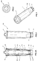
- a filter cartridge for machines for the preparation of hot beverages such as, for example, coffee, tea or barley coffee (orzo), is generally designated 100.
- the filter cartridge 100 is of the type suitable for being installed in a reservoir which is intended to contain water to be used for the preparation of the beverage, which are not illustrated in the Figures.
- the filter cartridge 100 comprises a connection element 5 with respect to a relevant seat or, more generally, to an engagement portion, preferably constructed at the bottom of the reservoir.
- connection element 5 is constructed by means of a hexagonal portion, which engages in a removable manner in a seat having a complementary shape. It is evident that there may also be provided connection elements having different characteristics, such as, for example, a screw thread or a bayonet type system.
- the filter cartridge 100 comprises an outer housing 1, of elongate form, inside which there is received filtering material, such as, for example, ion exchange resins.
- filtering material such as, for example, ion exchange resins.
- the filter cartridge 100 further comprises an inlet 11 for drawing in water to be filtered and an outlet 12 for discharging water which has been filtered.
- the inlet 11 and the outlet 12 are constructed in the region of the same end of the cartridge 100, which, during use, is arranged adjacent to the bottom of the reservoir.
- the inlet 11 and outlet 12 are connected by means of a filtration path which is designated 10 and 20 in Figure 2A and the characteristics of which will be set out in greater detail below.
- the arrangement of the outlet 12 is such that it is arranged so as to be directed towards the seat formed on the bottom of the reservoir in such a manner that the water introduced from the inlet 11 flows towards the circuit of the coffee machine through the outlet 12 after passing along the filtration path 10, 20 and the filtering material present inside the housing.
- the inlet and/or outlet comprise/s a mesh or slot type filter, through which the water may pass but not the filtering material, thereby being retained inside the cartridge 100.
- the cartridge 100 further comprises a tubular body 2 which is arranged inside the housing 1 which separates the inlet 11 with respect to the outlet 12 in the region of the connecting extremities 5.
- a tubular body 2 which is arranged inside the housing 1 which separates the inlet 11 with respect to the outlet 12 in the region of the connecting extremities 5.
- the tubular body has a longitudinal extent which is less than that of the outer housing, in such a manner that, in the region of the extremity of the cartridge 100 at which the connection element 5 is defined, it separates the inlet and outlet, while, in the region of the opposite end, there remains defined a passage 13 for the water which places the chamber 10 in communication with an internal portion 20 of the tubular body 2.
- the filtration material is present both in the chamber 10 and inside the tubular body 2.
- the filtration path is defined by the chamber 10 and the internal portion 20 with respect to the tubular body 2.
- the filtering material can be housed at least along a limited portion of the filtration path, either located in the outer chamber 10 or in the internal portion 20.
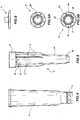
- the filter cartridge according to the present invention further comprises a plurality of partition elements 3 which, according to a preferred embodiment, extend radially from the tubular body 2 towards the outer housing 1. It will be anyhow apparent that according to an alternative embodiment the partition elements 3 can extend radially from the outer housing 1 towards the tubular body 2.
- the partition elements 3 allow subdivision of the outer chamber 10 or, more in general, the portion of the filtration path in which the filtering material is housed, into a plurality of respective sectors, thereby defining a series of compulsory passages for the water between the inlet 11 and outlet 12.
- the Applicant has observed that subdividing the portion of the filtration path in which the filtering material is housed into sectors results in a reduction of the phenomenon of canalization, because the filtering material has less freedom of movement and therefore it is more difficult to produce preferential passages for the water.
- the partition elements 3 are in the form of fins, that is to say, they have a planar shape.
- the partition elements 3 extend in a direction parallel with the longitudinal extent axis X of the filter cartridge 100 over such a length that they cover a part portion of the outer chamber 10 of the filtration path. In other words, the partition elements 3 extend as far as the other half of the outer chamber 10 in the direction of the axis X.
- the extent of the partition elements 3 in the direction of the longitudinal extent axis X is preferably shorter than the total length of the outer chamber 10. In that manner, the portion of the outer chamber 10 near the inlet 11 is not partitioned, allowing a better flow of the water being drawn into the cartridge 100.
- the partition elements 3 extend in a radial direction until they come into contact with the outer housing 1. It is thus evident that, in particular in the case in which the cartridge is constructed by assembling an outer housing and a tubular body, which are mutually formed as separate bodies, the radial extent of the partition elements 3 may be such that they extend as far as a position adjacent to the internal side wall of the housing 1, thereby leaving at least a minimum distance between partition elements 3 and the housing 1.
- the assembly may be brought about in a simple manner, yet obtaining the subdivision of the filtering material as illustrated above.
- the tubular body 2 comprises a collar 21 which is connected to a tubular portion 24 of the tubular body 2, which defines the second path portion 20.
- the connection is preferably brought about by means of a plurality of radial connection elements 22 which separate passages 23 for the water from each other.
- the collar 21 has dimensions and is positioned so as to be arranged in abutment with the side wall of the outer housing 1.
- the partition elements 3 extend in an axial direction from the collar 21 and are preferably formed as axial extensions of the connection elements 22.
- the presence of the collar therefore allows the tubular body 2 to be maintained in a coaxial state, or at least correctly positioned, with respect to the outer housing 1. In this manner, modifications which would make the flow of the water over the filtration path less uniform can be prevented in the form of the chamber defined between them.
- connection elements 22 are present in a larger number than the partition elements 3and are preferably of a thickness greater than them.
- the cartridge is constructed by forming the tubular body 2 and the housing 1 as separate bodies and subsequently assembling them by inserting one inside the other. In that case, a sufficient level of strength may be ensured for the structure and the risk of bending the partition elements 3 is limited, damage to which could compromise the correct operation of the cartridge.
- the tubular body 2 preferably comprises a coupling element 25 which is arranged in the region of an extremity of the tubular body 2 itself and which is intended to connect it to the outer housing 1, in the region of the opposite extremity to the one at which the collar 21 is constructed.
- the coupling element is constructed by means of a circular seat 25 which is capable of receiving the extremity of a second collar 51 which is constructed on the housing 1, in the region of the outlet 12.
- the assembly of the cartridge according to the present invention may therefore be brought about simply by inserting the tubular body 2 inside the housing 1, in a state guided by the collar 21 and the coupling element 25. Once those components are united, the filtering material can be introduced and therefore the outer housing can be closed by means of a closure element 4, preferably in the form of a cover, illustrated in Figure 6 .
- the invention solves the problem set out, at the same time resulting in a plurality of advantages.
- the presence of the partition elements 3 in fact prevents or at least limits the phenomena of canalization which are brought about in the filter cartridges which are constructed according to the prior art.
- the configuration of the partition elements used in the preferred embodiment of the invention ensures in any case optimum flow of water inside the cartridge as well as adequate filtration.
- the structure of the cartridge according to the present invention is particularly suitable for being brought about by means of stamping of single elements which can be readily assembled together, in any case ensuring a high level of strength and quality.
Claims (11)
- Filterkartusche (100) für eine Maschine zur Aufbereitung von Getränken mit einem Außengehäuse (1), dass sich überwiegend axial erstreckt, um Filtermaterial aufzunehmen, einem Verbindungsende (5) für einen Vorratsbehälter der Maschine, einem Einlass (11) zur Einleitung von Wasser, das gefiltert werden muss, und einem Auslass (12) zur Abgabe des gefilterten Wassers, einem rohrförmigen Körper (2), der innerhalb des Außengehäuses (1) derart aufgenommen ist, um den Einlass (11) und den Auslass (12) in der Umgebung des Verbindungsendes (5) zu trennen und um einen Filtrierweg (10, 20) zu definieren, der den Einlass (11) mit dem Auslass (12) verbindet, wobei das Filtermaterial zumindest entlang eines Bereichs des Filtrierwegs (10, 20) aufgenommen ist, dadurch gekennzeichnet, dass sie ferner eine Mehrzahl von Trennelementen (3) aufweist, die sich radial vom rohrförmigen Körper (2) oder vom Außengehäuse (1) erstrecken, um so den Bereich, der das Filtermaterial aufnimmt, in eine Mehrzahl von jeweiligen Abschnitten zu teilen.
- Filterkartusche (100) gemäß Anspruch 1, wobei eine Außenkammer (10) zwischen dem Außengehäuse und dem rohrförmigen Körper gebildet ist, das Filtermaterial innerhalb der Außenkammer (10) aufgenommen ist, sich die Trennelemente (3) innerhalb der Außenkammer (10) erstrecken.
- Filterkartusche (100) gemäß Anspruch 1 oder 2, wobei das Filtermaterial ferner innerhalb des rohrförmigen Körpers (2) aufgenommen ist, der einen zweiten Bereich (20) des Filtrierwegs (10, 20) definiert.
- Filterkartusche (100) gemäß einem der vorhergehenden Ansprüche, wobei die Trennelemente (3) in der Form von Rippen sind.
- Filterkartusche (100) gemäß einem der vorhergehenden Ansprüche, wobei sich die Trennelemente (3) in eine Richtung erstrecken, die parallel zu einer Achse (X) einer Längsausdehnung der Filterkartusche (100) sind.
- Filterkartusche (100) gemäß Anspruch 5, wobei der Bereich das Filtermaterial aufnimmt und entlang dem sich die Trennelemente (3) über einem überwiegenden Teil des Filtrierweges erstrecken.
- Filterkartusche (100) gemäß Anspruch 5 oder 6, wobei sich die Trennelemente (3) in die Richtung der Achse (X) über eine Länge erstrecken, die kürzer ist als die der Außenkammer (10).
- Filterkartusche (100) gemäß einem der vorhergehenden Ansprüche, wobei sich die Trennelemente (3) in eine radiale Richtung derart erstrecken, um benachbart zum oder in Kontakt mit dem Außengehäuse (1) zu sein.
- Filterkartusche (100) gemäß einem der vorhergehenden Ansprüche, wobei der rohrförmige Körper (2) einen Kragen (21) aufweist, der mit einem rohrförmigen Bereich (24) des rohrförmigen Körpers (2) durch eine Mehrzahl von radialen Verbindungselementen (22) verbunden ist, die jeweilige Durchgänge (23) für das Wasser bilden, wobei der Kragen (21) in Anlage mit einer inneren Seitenwand des Außengehäuses (1) angeordnet ist.
- Filterkartusche (100) gemäß Anspruch 9, wobei die Verbindungselemente (22) in einer größeren Anzahl als die Trennelemente (3) vorhanden sind.
- Filterkartusche (100) gemäß einem der vorhergehenden Ansprüche, wobei der rohrförmige Körper (2) ein Kupplungselement (25) aufweist, das an einem Ende des rohrförmigen Körpers (2) angeordnet ist und den rohrförmigen Körper (2) mit dem Außengehäuse (1) an diesem Ende verbinden kann.
Priority Applications (1)
| Application Number | Priority Date | Filing Date | Title |
|---|---|---|---|
| PL15178539T PL2979593T3 (pl) | 2014-08-01 | 2015-07-27 | Wkład filtracyjny do maszyny do przygotowania napojów |
Applications Claiming Priority (1)
| Application Number | Priority Date | Filing Date | Title |
|---|---|---|---|
| ITPD20140213 | 2014-08-01 |
Publications (2)
| Publication Number | Publication Date |
|---|---|
| EP2979593A1 EP2979593A1 (de) | 2016-02-03 |
| EP2979593B1 true EP2979593B1 (de) | 2017-10-18 |
Family
ID=51663304
Family Applications (1)
| Application Number | Title | Priority Date | Filing Date |
|---|---|---|---|
| EP15178539.1A Active EP2979593B1 (de) | 2014-08-01 | 2015-07-27 | Filterpatrone für maschine zur herstellung von getränken |
Country Status (3)
| Country | Link |
|---|---|
| EP (1) | EP2979593B1 (de) |
| CN (1) | CN105310505B (de) |
| PL (1) | PL2979593T3 (de) |
Family Cites Families (8)
| Publication number | Priority date | Publication date | Assignee | Title |
|---|---|---|---|---|
| BE44189A (de) * | 1936-06-07 | |||
| DE19827623A1 (de) | 1997-07-04 | 1999-01-07 | Aweco Kunststofftech Geraete | Wasserbehälter mit Filterpatrone |
| US6487961B2 (en) * | 2001-01-29 | 2002-12-03 | Bunn-O-Matic Corporation | Brewing basket for a brewing funnel |
| DE10233475A1 (de) * | 2002-07-24 | 2004-02-19 | Hydac Filtertechnik Gmbh | Filterelement zum Filtrieren von Fluiden |
| ATE348559T1 (de) * | 2003-07-17 | 2007-01-15 | Saeco Ipr Ltd | Filterpatrone für wasserbehälter von kaffeemaschinen |
| DE102004049876C5 (de) * | 2004-10-13 | 2010-04-29 | Brita Gmbh | Filterkartusche |
| AU2011311170A1 (en) * | 2010-10-07 | 2013-05-30 | Amiad Water Systems Ltd. | Filtration unit and system |
| ITPD20130051A1 (it) * | 2013-03-01 | 2014-09-02 | Laica Spa | Filtro e serbatoio per macchina per la preparazione di bevande calde |
-
2015
- 2015-07-27 PL PL15178539T patent/PL2979593T3/pl unknown
- 2015-07-27 EP EP15178539.1A patent/EP2979593B1/de active Active
- 2015-08-03 CN CN201510471441.4A patent/CN105310505B/zh active Active
Non-Patent Citations (1)
| Title |
|---|
| None * |
Also Published As
| Publication number | Publication date |
|---|---|
| CN105310505B (zh) | 2020-01-10 |
| PL2979593T3 (pl) | 2018-01-31 |
| EP2979593A1 (de) | 2016-02-03 |
| CN105310505A (zh) | 2016-02-10 |
Similar Documents
| Publication | Publication Date | Title |
|---|---|---|
| EP2160359B1 (de) | Filterpatrone für durchströmende filterkanne und herstellungsverfahren | |
| EP2961298B1 (de) | Filter und tank für eine maschine zur herstellung von heissgetränken | |
| KR100874751B1 (ko) | 정수기용 복합필터 조립체 | |
| ITBO20120104A1 (it) | Capsula intercambiabile per la preparazione di una infusione di un prodotto in polvere, e relativo procedimento per l'ottenimento di una tale infusione | |
| EP2979593B1 (de) | Filterpatrone für maschine zur herstellung von getränken | |
| EP2899164A1 (de) | Vorrichtung und Verfahren zur Konditionierung einer wässrigen Flüssigkeit wie etwa Trinkwasser | |
| CN108349750B (zh) | 渗透型过滤设备 | |
| JP6351635B2 (ja) | コーヒーポッドアダプタシステム | |
| CA3112280A1 (en) | Device and method for filtering a fluid circulating in a plumbing and heating system | |
| EP2704994B1 (de) | Vorrichtung zur wasseraufbereitung | |
| JP2003093236A (ja) | 抽出飲料製造装置 | |
| US10524456B2 (en) | Filtering device for aquariums and the like | |
| US11718550B2 (en) | Cartridge for water treatment for a device for water treatment, a head of a device for water treatment and a device for water treatment comprising such a cartridge and such a head | |
| US10995479B2 (en) | Aircraft | |
| CN102935304A (zh) | 一种两用过滤净水器 | |
| KR101894544B1 (ko) | 정수기용 필터 카트리지 | |
| EP3221268A1 (de) | Filterpatrone für einen getränkezubereitungsautomaten | |
| US20160309950A1 (en) | Filter assembly and a reservoir for an appliance | |
| CN213171590U (zh) | 用于反渗透滤芯的中心管、反渗透滤芯和净水机 | |
| CN218164874U (zh) | 水箱具有过滤功能的电蒸锅 | |
| KR101520006B1 (ko) | 직수 예열 기능이 구비된 온수 공급장치 | |
| EP2555662A2 (de) | Doppelfunktionsanschlussstück für einen geschirrspüler | |
| KR200484573Y1 (ko) | 생맥주 인출장치 | |
| EP3351511B1 (de) | Vorrichtung zur aufbereitung von brauchwasser | |
| KR20120131446A (ko) | 온수공급장치 |
Legal Events
| Date | Code | Title | Description |
|---|---|---|---|
| PUAI | Public reference made under article 153(3) epc to a published international application that has entered the european phase |
Free format text: ORIGINAL CODE: 0009012 |
|
| AK | Designated contracting states |
Kind code of ref document: A1 Designated state(s): AL AT BE BG CH CY CZ DE DK EE ES FI FR GB GR HR HU IE IS IT LI LT LU LV MC MK MT NL NO PL PT RO RS SE SI SK SM TR |
|
| AX | Request for extension of the european patent |
Extension state: BA ME |
|
| 17P | Request for examination filed |
Effective date: 20160803 |
|
| RBV | Designated contracting states (corrected) |
Designated state(s): AL AT BE BG CH CY CZ DE DK EE ES FI FR GB GR HR HU IE IS IT LI LT LU LV MC MK MT NL NO PL PT RO RS SE SI SK SM TR |
|
| R17P | Request for examination filed (corrected) |
Effective date: 20160803 |
|
| RIC1 | Information provided on ipc code assigned before grant |
Ipc: A47J 31/60 20060101AFI20170302BHEP |
|
| GRAP | Despatch of communication of intention to grant a patent |
Free format text: ORIGINAL CODE: EPIDOSNIGR1 |
|
| INTG | Intention to grant announced |
Effective date: 20170509 |
|
| RAP1 | Party data changed (applicant data changed or rights of an application transferred) |
Owner name: LAICA S.P.A. |
|
| GRAS | Grant fee paid |
Free format text: ORIGINAL CODE: EPIDOSNIGR3 |
|
| GRAA | (expected) grant |
Free format text: ORIGINAL CODE: 0009210 |
|
| AK | Designated contracting states |
Kind code of ref document: B1 Designated state(s): AL AT BE BG CH CY CZ DE DK EE ES FI FR GB GR HR HU IE IS IT LI LT LU LV MC MK MT NL NO PL PT RO RS SE SI SK SM TR |
|
| REG | Reference to a national code |
Ref country code: GB Ref legal event code: FG4D |
|
| REG | Reference to a national code |
Ref country code: CH Ref legal event code: EP |
|
| REG | Reference to a national code |
Ref country code: AT Ref legal event code: REF Ref document number: 937196 Country of ref document: AT Kind code of ref document: T Effective date: 20171115 Ref country code: IE Ref legal event code: FG4D |
|
| REG | Reference to a national code |
Ref country code: DE Ref legal event code: R096 Ref document number: 602015005395 Country of ref document: DE |
|
| REG | Reference to a national code |
Ref country code: NL Ref legal event code: MP Effective date: 20171018 |
|
| REG | Reference to a national code |
Ref country code: LT Ref legal event code: MG4D |
|
| PG25 | Lapsed in a contracting state [announced via postgrant information from national office to epo] |
Ref country code: NL Free format text: LAPSE BECAUSE OF FAILURE TO SUBMIT A TRANSLATION OF THE DESCRIPTION OR TO PAY THE FEE WITHIN THE PRESCRIBED TIME-LIMIT Effective date: 20171018 |
|
| PG25 | Lapsed in a contracting state [announced via postgrant information from national office to epo] |
Ref country code: ES Free format text: LAPSE BECAUSE OF FAILURE TO SUBMIT A TRANSLATION OF THE DESCRIPTION OR TO PAY THE FEE WITHIN THE PRESCRIBED TIME-LIMIT Effective date: 20171018 Ref country code: SE Free format text: LAPSE BECAUSE OF FAILURE TO SUBMIT A TRANSLATION OF THE DESCRIPTION OR TO PAY THE FEE WITHIN THE PRESCRIBED TIME-LIMIT Effective date: 20171018 Ref country code: NO Free format text: LAPSE BECAUSE OF FAILURE TO SUBMIT A TRANSLATION OF THE DESCRIPTION OR TO PAY THE FEE WITHIN THE PRESCRIBED TIME-LIMIT Effective date: 20180118 Ref country code: FI Free format text: LAPSE BECAUSE OF FAILURE TO SUBMIT A TRANSLATION OF THE DESCRIPTION OR TO PAY THE FEE WITHIN THE PRESCRIBED TIME-LIMIT Effective date: 20171018 Ref country code: LT Free format text: LAPSE BECAUSE OF FAILURE TO SUBMIT A TRANSLATION OF THE DESCRIPTION OR TO PAY THE FEE WITHIN THE PRESCRIBED TIME-LIMIT Effective date: 20171018 |
|
| PG25 | Lapsed in a contracting state [announced via postgrant information from national office to epo] |
Ref country code: RS Free format text: LAPSE BECAUSE OF FAILURE TO SUBMIT A TRANSLATION OF THE DESCRIPTION OR TO PAY THE FEE WITHIN THE PRESCRIBED TIME-LIMIT Effective date: 20171018 Ref country code: LV Free format text: LAPSE BECAUSE OF FAILURE TO SUBMIT A TRANSLATION OF THE DESCRIPTION OR TO PAY THE FEE WITHIN THE PRESCRIBED TIME-LIMIT Effective date: 20171018 Ref country code: IS Free format text: LAPSE BECAUSE OF FAILURE TO SUBMIT A TRANSLATION OF THE DESCRIPTION OR TO PAY THE FEE WITHIN THE PRESCRIBED TIME-LIMIT Effective date: 20180218 Ref country code: HR Free format text: LAPSE BECAUSE OF FAILURE TO SUBMIT A TRANSLATION OF THE DESCRIPTION OR TO PAY THE FEE WITHIN THE PRESCRIBED TIME-LIMIT Effective date: 20171018 Ref country code: BG Free format text: LAPSE BECAUSE OF FAILURE TO SUBMIT A TRANSLATION OF THE DESCRIPTION OR TO PAY THE FEE WITHIN THE PRESCRIBED TIME-LIMIT Effective date: 20180118 Ref country code: GR Free format text: LAPSE BECAUSE OF FAILURE TO SUBMIT A TRANSLATION OF THE DESCRIPTION OR TO PAY THE FEE WITHIN THE PRESCRIBED TIME-LIMIT Effective date: 20180119 |
|
| REG | Reference to a national code |
Ref country code: DE Ref legal event code: R097 Ref document number: 602015005395 Country of ref document: DE |
|
| PG25 | Lapsed in a contracting state [announced via postgrant information from national office to epo] |
Ref country code: CZ Free format text: LAPSE BECAUSE OF FAILURE TO SUBMIT A TRANSLATION OF THE DESCRIPTION OR TO PAY THE FEE WITHIN THE PRESCRIBED TIME-LIMIT Effective date: 20171018 Ref country code: DK Free format text: LAPSE BECAUSE OF FAILURE TO SUBMIT A TRANSLATION OF THE DESCRIPTION OR TO PAY THE FEE WITHIN THE PRESCRIBED TIME-LIMIT Effective date: 20171018 Ref country code: EE Free format text: LAPSE BECAUSE OF FAILURE TO SUBMIT A TRANSLATION OF THE DESCRIPTION OR TO PAY THE FEE WITHIN THE PRESCRIBED TIME-LIMIT Effective date: 20171018 Ref country code: SK Free format text: LAPSE BECAUSE OF FAILURE TO SUBMIT A TRANSLATION OF THE DESCRIPTION OR TO PAY THE FEE WITHIN THE PRESCRIBED TIME-LIMIT Effective date: 20171018 |
|
| PLBE | No opposition filed within time limit |
Free format text: ORIGINAL CODE: 0009261 |
|
| STAA | Information on the status of an ep patent application or granted ep patent |
Free format text: STATUS: NO OPPOSITION FILED WITHIN TIME LIMIT |
|
| PG25 | Lapsed in a contracting state [announced via postgrant information from national office to epo] |
Ref country code: RO Free format text: LAPSE BECAUSE OF FAILURE TO SUBMIT A TRANSLATION OF THE DESCRIPTION OR TO PAY THE FEE WITHIN THE PRESCRIBED TIME-LIMIT Effective date: 20171018 Ref country code: SM Free format text: LAPSE BECAUSE OF FAILURE TO SUBMIT A TRANSLATION OF THE DESCRIPTION OR TO PAY THE FEE WITHIN THE PRESCRIBED TIME-LIMIT Effective date: 20171018 |
|
| 26N | No opposition filed |
Effective date: 20180719 |
|
| PG25 | Lapsed in a contracting state [announced via postgrant information from national office to epo] |
Ref country code: SI Free format text: LAPSE BECAUSE OF FAILURE TO SUBMIT A TRANSLATION OF THE DESCRIPTION OR TO PAY THE FEE WITHIN THE PRESCRIBED TIME-LIMIT Effective date: 20171018 |
|
| PG25 | Lapsed in a contracting state [announced via postgrant information from national office to epo] |
Ref country code: MC Free format text: LAPSE BECAUSE OF FAILURE TO SUBMIT A TRANSLATION OF THE DESCRIPTION OR TO PAY THE FEE WITHIN THE PRESCRIBED TIME-LIMIT Effective date: 20171018 Ref country code: LU Free format text: LAPSE BECAUSE OF NON-PAYMENT OF DUE FEES Effective date: 20180727 |
|
| REG | Reference to a national code |
Ref country code: BE Ref legal event code: MM Effective date: 20180731 |
|
| PG25 | Lapsed in a contracting state [announced via postgrant information from national office to epo] |
Ref country code: FR Free format text: LAPSE BECAUSE OF NON-PAYMENT OF DUE FEES Effective date: 20180731 |
|
| REG | Reference to a national code |
Ref country code: IE Ref legal event code: MM4A |
|
| PG25 | Lapsed in a contracting state [announced via postgrant information from national office to epo] |
Ref country code: BE Free format text: LAPSE BECAUSE OF NON-PAYMENT OF DUE FEES Effective date: 20180731 |
|
| PG25 | Lapsed in a contracting state [announced via postgrant information from national office to epo] |
Ref country code: IE Free format text: LAPSE BECAUSE OF NON-PAYMENT OF DUE FEES Effective date: 20180727 |
|
| PG25 | Lapsed in a contracting state [announced via postgrant information from national office to epo] |
Ref country code: MT Free format text: LAPSE BECAUSE OF NON-PAYMENT OF DUE FEES Effective date: 20180727 |
|
| PG25 | Lapsed in a contracting state [announced via postgrant information from national office to epo] |
Ref country code: TR Free format text: LAPSE BECAUSE OF FAILURE TO SUBMIT A TRANSLATION OF THE DESCRIPTION OR TO PAY THE FEE WITHIN THE PRESCRIBED TIME-LIMIT Effective date: 20171018 |
|
| REG | Reference to a national code |
Ref country code: AT Ref legal event code: UEP Ref document number: 937196 Country of ref document: AT Kind code of ref document: T Effective date: 20171018 |
|
| PG25 | Lapsed in a contracting state [announced via postgrant information from national office to epo] |
Ref country code: PT Free format text: LAPSE BECAUSE OF FAILURE TO SUBMIT A TRANSLATION OF THE DESCRIPTION OR TO PAY THE FEE WITHIN THE PRESCRIBED TIME-LIMIT Effective date: 20171018 |
|
| PG25 | Lapsed in a contracting state [announced via postgrant information from national office to epo] |
Ref country code: HU Free format text: LAPSE BECAUSE OF FAILURE TO SUBMIT A TRANSLATION OF THE DESCRIPTION OR TO PAY THE FEE WITHIN THE PRESCRIBED TIME-LIMIT; INVALID AB INITIO Effective date: 20150727 Ref country code: CY Free format text: LAPSE BECAUSE OF FAILURE TO SUBMIT A TRANSLATION OF THE DESCRIPTION OR TO PAY THE FEE WITHIN THE PRESCRIBED TIME-LIMIT Effective date: 20171018 Ref country code: MK Free format text: LAPSE BECAUSE OF NON-PAYMENT OF DUE FEES Effective date: 20171018 |
|
| PG25 | Lapsed in a contracting state [announced via postgrant information from national office to epo] |
Ref country code: AL Free format text: LAPSE BECAUSE OF FAILURE TO SUBMIT A TRANSLATION OF THE DESCRIPTION OR TO PAY THE FEE WITHIN THE PRESCRIBED TIME-LIMIT Effective date: 20171018 |
|
| PGFP | Annual fee paid to national office [announced via postgrant information from national office to epo] |
Ref country code: IT Payment date: 20230613 Year of fee payment: 9 |
|
| PGFP | Annual fee paid to national office [announced via postgrant information from national office to epo] |
Ref country code: PL Payment date: 20230621 Year of fee payment: 9 |
|
| PGFP | Annual fee paid to national office [announced via postgrant information from national office to epo] |
Ref country code: GB Payment date: 20230720 Year of fee payment: 9 Ref country code: CH Payment date: 20230801 Year of fee payment: 9 Ref country code: AT Payment date: 20230720 Year of fee payment: 9 |
|
| PGFP | Annual fee paid to national office [announced via postgrant information from national office to epo] |
Ref country code: DE Payment date: 20230719 Year of fee payment: 9 |