EP2979568B1 - Shoe for indoor sports - Google Patents
Shoe for indoor sports Download PDFInfo
- Publication number
- EP2979568B1 EP2979568B1 EP13880141.0A EP13880141A EP2979568B1 EP 2979568 B1 EP2979568 B1 EP 2979568B1 EP 13880141 A EP13880141 A EP 13880141A EP 2979568 B1 EP2979568 B1 EP 2979568B1
- Authority
- EP
- European Patent Office
- Prior art keywords
- roll
- reinforcement plate
- big toe
- posterior
- toe
- Prior art date
- Legal status (The legal status is an assumption and is not a legal conclusion. Google has not performed a legal analysis and makes no representation as to the accuracy of the status listed.)
- Active
Links
- 230000002787 reinforcement Effects 0.000 claims description 49
- 210000001255 hallux Anatomy 0.000 claims description 34
- 210000002683 foot Anatomy 0.000 claims description 27
- 210000000454 fifth toe Anatomy 0.000 claims description 16
- 210000001872 metatarsal bone Anatomy 0.000 claims description 10
- 210000003371 toe Anatomy 0.000 claims description 10
- 229920005989 resin Polymers 0.000 claims description 3
- 239000011347 resin Substances 0.000 claims description 3
- 210000001503 joint Anatomy 0.000 description 11
- 239000000463 material Substances 0.000 description 4
- 210000000453 second toe Anatomy 0.000 description 3
- 241001272720 Medialuna californiensis Species 0.000 description 2
- 210000000988 bone and bone Anatomy 0.000 description 2
- 238000010586 diagram Methods 0.000 description 2
- 210000003127 knee Anatomy 0.000 description 2
- 238000012986 modification Methods 0.000 description 2
- 230000004048 modification Effects 0.000 description 2
- 238000000465 moulding Methods 0.000 description 2
- 238000012421 spiking Methods 0.000 description 2
- 229920005992 thermoplastic resin Polymers 0.000 description 2
- 239000006096 absorbing agent Substances 0.000 description 1
- 238000007796 conventional method Methods 0.000 description 1
- 230000000694 effects Effects 0.000 description 1
- 210000001906 first metatarsal bone Anatomy 0.000 description 1
- 210000000610 foot bone Anatomy 0.000 description 1
- 230000009191 jumping Effects 0.000 description 1
- 238000000034 method Methods 0.000 description 1
- 210000000452 mid-foot Anatomy 0.000 description 1
- 230000035939 shock Effects 0.000 description 1
- 238000003466 welding Methods 0.000 description 1
Images


Classifications
-
- A—HUMAN NECESSITIES
- A43—FOOTWEAR
- A43B—CHARACTERISTIC FEATURES OF FOOTWEAR; PARTS OF FOOTWEAR
- A43B13/00—Soles; Sole-and-heel integral units
- A43B13/14—Soles; Sole-and-heel integral units characterised by the constructive form
- A43B13/18—Resilient soles
- A43B13/187—Resiliency achieved by the features of the material, e.g. foam, non liquid materials
-
- A—HUMAN NECESSITIES
- A43—FOOTWEAR
- A43B—CHARACTERISTIC FEATURES OF FOOTWEAR; PARTS OF FOOTWEAR
- A43B13/00—Soles; Sole-and-heel integral units
- A43B13/02—Soles; Sole-and-heel integral units characterised by the material
- A43B13/026—Composites, e.g. carbon fibre or aramid fibre; the sole, one or more sole layers or sole part being made of a composite
-
- A—HUMAN NECESSITIES
- A43—FOOTWEAR
- A43B—CHARACTERISTIC FEATURES OF FOOTWEAR; PARTS OF FOOTWEAR
- A43B13/00—Soles; Sole-and-heel integral units
- A43B13/14—Soles; Sole-and-heel integral units characterised by the constructive form
- A43B13/18—Resilient soles
- A43B13/181—Resiliency achieved by the structure of the sole
- A43B13/185—Elasticated plates sandwiched between two interlocking components, e.g. thrustors
Definitions
- the present invention relates to a shoe suitable for indoor sports such as volleyball, for example.
- This conventional example will increase the jump speed. Also, this structure will only be effective for the right foot of a right-footed player during a jump.
- the present invention is directed to a shoe for indoor sports including:
- the reinforcement plate of the present invention extends from posterior of heads of the proximal phalanges of the big toe and the little toe to anterior of the tip of the foot, and the reinforcement plate in the roll-up portion is rolled up from the front portion of the base portion upwardly above the upper surface of the front end portion of the midsole.
- a part or whole of the front surface of the roll-up portion of the reinforcement plate of the present invention is covered by an anti-slip member. This reduces the slip, making it possible to realize an intended play (action).
- the roll-up portion projects upwardly by 0.3 cm to 3.0 cm with respect to the upper surface of the mid sole.
- the projection height of the roll-up portion is less than 0.3 cm, the advantageous effect set forth above will be insufficient, whereas if the projection height exceeds 3.0 cm, the rigidity of the toe of the shoe will be excessive.
- the projection height is set more preferably to 0.4 cm to 2.0 cm, and most preferably to 0.4 cm to 1.5 cm.
- a position of an upper end of the roll-up portion covering an anterior of a distal phalanx of the big toe is set to be below an upper surface of a base of the distal phalanx of the big toe.
- the roll-up portion covering the distal phalanx may have openings (through holes) or cutouts.
- the base plate portion continuously extends to posterior of metatarsal phalangeal joints (MP joints) of the big toe and the little toe.
- MP joints metatarsal phalangeal joints
- the reinforcement plate further integrally includes a connecting bar connecting together a medial side and a lateral side of the base plate portion, and a medial side end of the connecting bar is arranged posterior to a lateral side end thereof, and the connecting bar extends anterior as the connecting bar extends toward a lateral side.
- the connecting bar extends in a direction crossing the array of MP joints of the foot. Therefore, it is possible to further reduce excessive extension of the MP joints.
- the base plate portion extends to posterior of a Lisfranc joint on the medial side and the lateral side of the foot.
- the anti-slip member covers the roll-up portion from a lower end to an upper end thereof.
- the resin roll-up portion will not come into contact with the floor surface, and it is therefore possible to reliably reduce the slip.
- the anti-slip member does not need to cover the entire surface of the roll-up portion, but openings (through holes) may be provided in the anti-slip member so that the reinforcement plate is slightly visible from the front side.
- the base plate portion includes a lateral edge portion extending from the front portion in a posterior direction so as to cover a lateral edge of the mid sole, a lateral roll-up portion rolled up upwardly from the lateral edge portion, and a medial side portion spaced apart from a medial edge of the mid sole and extending from the front portion to posterior of a ball of the big toe along the medial edge so as to cover at least a portion of the big toe.
- the medial side portion of the base portion extending along the big toe assists the flexion of the MP joint of the big toe having been extended during a jump, thereby increasing the jump height.
- the lateral edge portion and the lateral roll-up portion extending along the lateral edge of the midsole not only assist the flexion on the little toe side, but also reduce the shifting of the foot toward the lateral side during landing or receiving.
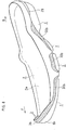
- FIG. 1 to FIG. 6 show Embodiment 1. Note that the figures do not show the upper of the shoe.
- the present embodiment is, for example, a shoe for volleyball.
- the sole shown in FIG. 1 includes an outsole 1, a midsole 2 and a reinforcement plate 3 integrally layered together via bonding or welding.
- the outsole 1 shown in FIG. 6 is formed by a foamed material or a non-foamed material of a rubber, and has a greater frictional force on the floor surface than the midsole 2 and the reinforcement plate 3.
- the outsole 1 includes a tread surface 1s to be in contact with the floor surface, and a roll-up portion at the front end forming an anti-slip member 1b to be described later.
- the midsole 2 is arranged upward Z of the outsole 1, and covers the entire area of the sole of the foot.
- the midsole 2 is formed mainly by a foamed material having a thermoplastic resin component such as EVA, for example, and absorbs the impact of landing. Note that as shown in FIG. 1 , a portion of the midsole 2 may have a rubber-like elastic shock absorber 29, etc.
- An insole (inner sole) (not shown) is bonded on the midsole 2.
- a sock liner is further attached on the insole in an upper (not shown). Note that an upper is for covering and wrapping the instep of the foot.
- the reinforcement plate 3 is formed by a non-foamed material containing a thermoplastic resin component, and has a Young's modulus greater than the Young's modulus of the outsole 1 and the Young's modulus of the midsole 2.
- the preferred Young's modulus value of the reinforcement plate 3 is 20 to 500 Mpa, more preferably 40 to 200 Mpa.
- the reinforcement plate 3 is arranged between the outsole 1 and the midsole 2.
- the reinforcement plate 3 is sandwiched between an upper surface 1a of the outsole 1 and a lower surface 2b of the midsole 2.
- the reinforcement plate 3 may be arranged between the upper and lower layers of the midsole 2. Therefore, there is no particular limitation as long as the reinforcement plate 3 is arranged between the outsole 1 and the midsole 2.
- B1 denotes the big toe
- B2 the second toe
- B5 the little toe
- B11, B21 and B51 denote their respective distal phalanges
- B13, B23 and B53 their respective proximal phalanges
- B14, B24 and B54 their respective metatarsal bones.
- the reinforcement plate 3 includes a base portion 3a, a front roll-up portion 3b, a connecting bar 3c, a lateral edge portion 30, a medial side portion 31 and a shank portion 32, which are provided as a loop-shaped integral part.
- the reinforcement plate 3 does not cover the toes including the big toe B1 and the little toe B5 from directly above.
- the base portion 3a extends from posterior B of the heads of the proximal phalanges B13 and B53 of the big toe B1 and the little toe B5 to anterior F of the tip of the foot.
- a front portion 3f of the reinforcement plate 3 is curved, and continuously extends from the medial side Me toward the lateral side La.
- a head refers to a portion of each bone that is close to the anterior joint and that is slightly expanding to a greater thickness and it is referred to also as a distal head.
- a base refers to a portion of each bone that is close to the posterior joint and that is slightly expanding to a greater thickness and it is referred to also as a proximal head.
- the front roll-up portion 3b is integrally continuous with the front portion 3f of the base portion 3a, and extends to anterior F of the front end of the midsole 2 while projecting, from the front portion 3f, upward Z of an upper surface 2a of a front end portion 2e of the midsole 2. Moreover, the front roll-up portion 3b is rolled up upward Z, and covers the anterior F of the big toe B1 as shown in FIG. 1 . That is, the front roll-up portion 3b extends along the midsole 2 toward an upper-forward diagonal direction past the front end of the midsole 2, and projects from the upper surface 2a at the front end of the midsole 2 in a crescent shape or a half-moon shape.
- the front roll-up portion 3b is covered, from the lower end to the upper end of the front roll-up portion 3b, with the anti-slip member 1b of the outsole 1, as shown in FIG. 1 and FIG. 6 . Note that the front roll-up portion 3b and the anti-slip member 1b cover the toe portion of the upper (not shown).
- the anti-slip member 1b of FIG. 1 may be separate from the outsole 1. Small through holes or cutouts may be provided in the anti-slip member 1b so that the front roll-up portion 3b is partly visible from the front side.
- the front roll-up portion 3b is projecting upwardly by 0.3 cm to 3.0 cm with respect to the upper surface 2a of the midsole 2 as shown in FIG. 6 . More preferably, the amount of projection ⁇ H is 0.4 cm to 2.0 cm.
- the position of the upper end of the front roll-up portion 3b covering the distal phalanx B11 of the big toe B1 is set to be below an upper surface F11 of the base of the distal phalanx B11 of the big toe B1.
- the base portion 3a continuously extends to posterior B of the metatarsal phalangeal joints MP of the big toe B1 and the little toe B5. Moreover, the base portion 3a extends to posterior B of the Lisfranc joint R on the medial side Me and the lateral side La of the foot.
- the base portion 3a includes the lateral edge portion 30, a lateral roll-up portion 30b, the medial side portion 31 and the shank portion 32 as an integral part.
- the lateral edge portion 30 of FIG. 2 extends toward the posterior B direction from the front portion 3f so as to cover a lateral edge 21 of the midsole 2.
- the lateral roll-up portion 30b is rolled up upward Z from the lateral edge portion 30.
- the medial side portion 31 is spaced apart from a medial edge 2m of the midsole 2, and extends from the front portion 3f along the medial edge 2m to posterior B of the ball BO of the big toe of FIG. 5 , covering at least a portion of the big toe B1.
- the base portion 3a of the reinforcement plate 3 is formed in a continuous loop shape extending from the front portion 3f and the front roll-up portion 3b to the shank portion 32 via the lateral edge portion 30 and the medial side portion 31.
- the shank portion 32 reinforces the arch, as is well known in the art.
- the reinforcement plate 3 further integrally includes the connecting bar 3c connecting together the medial side Me and the lateral side La of the base portion 3a.
- a medial end 3m of the connecting bar 3c is arranged posterior B to a lateral end 31 thereof.
- the connecting bar 3c extends anterior F as it extends toward the lateral side La.
- the connecting bar 3c defines two through holes H1 and H2 in the loop-shaped reinforcement plate 3.
- the connecting bar 3c will reduce excessive extension of the MP joints MP from the second toe B2 to the little toe B5.
- both knees are bent, and then the MP joints are extended while extending the knees, thereby first lifting the right foot in the air, and then lifting the left foot in the art.
- FIG. 7A shows the results of a test on the relationship between the floor reaction force Fz and the jump efficiency ⁇ Fz
- FIG. 7B shows the results of a test on the relationship between the jump efficiency ⁇ Fz and the jump height.
- the jump efficiency ⁇ Fz which is dotted in FIG. 7A , i.e., the impulse ⁇ Fz from when the floor reaction force Fz peaks until the foot comes completely off the floor, is speculated to have a strong correlation with the jump height as shown in FIG. 7B .
- the MP joint remains extended while the toes anterior thereto kicks the floor surface. If it is made easier to exert power at the toes and kick the floor surface immediately before the take-off, the impulse ⁇ Fz will be the primary area ⁇ 1 (dotted) plus the additional area ⁇ 2 (hatched). This will increase the jump height.
- the upper portion of the front roll-up portion 3b is exposed from the anti-slip member 1b, which is a roll-up portion of the outsole 1.
- the exposed front roll-up portion 3b is large, and it will further increase the jump height when spiking.
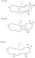
- FIGS. 9A to 9C show still other examples.
- the connecting bar 3c is absent.
- the front portion 3f of the reinforcement plate 3 is formed in a half-moon shape.
- the reinforcement plate 3 of FIG. 5 may be provided extending from the front roll-up portion 3b to posterior B of the heads of the proximal phalanges B13 and B53 of the big toe B1 and the little toe B5, and may be absent posterior B to the heads.
- the reinforcement plate 3 may be provided in a U-letter shape extending from the front roll-up portion 3b to posterior B of the heads of the metatarsal bone B14 and B54 of the big toe B1 and the little toe B5, and may be absent posterior B to the heads.
- the lateral edge portion 30 and the medial side portion 31 extending toward the anterior F direction from the shank portion 32, with the front end portions of the lateral edge portion 30 and the medial side portion 31 overlapping the rear end portion of the base portion 3a of the reinforcement plate 3 over a portion of the foot in the long axis direction.
- the reinforcement plate 3 may be provided as an integral part of the midsole 2 in the post molding (secondary molding process) of the midsole 2.
- the subject structure may be provided only for the left foot or the right foot, but it may be provided for both of the left foot and the right foot.
- the present invention is applicable to shoes for indoor sports such as volleyball.
Landscapes
- Chemical & Material Sciences (AREA)
- Engineering & Computer Science (AREA)
- Materials Engineering (AREA)
- Footwear And Its Accessory, Manufacturing Method And Apparatuses (AREA)
Description
- The present invention relates to a shoe suitable for indoor sports such as volleyball, for example.
- In volleyball, most jumps are jumps made with both feet. There are volleyball shoes currently sold, having a structure in which a reinforcement plate is elongated from the midfoot portion to the head of the first metatarsal bone to reduce excessive extension (dorsiflexion) of the metatarsal phalangeal joint (MP joint), thereby effectively transmitting, to the floor surface, the horizontal kicking force of the right foot (a right-footed player) during a jump.
- This conventional example will increase the jump speed. Also, this structure will only be effective for the right foot of a right-footed player during a jump.
- This conventional technique, however, does not focus on the left foot, which has a greater contribution to the jump height (a right-footed player), and cannot so much increase the jump height.
-
- First Patent Document:
US4,412,393 B (front page) - Second Patent Document:
US4,453,996 B (front page) - Third Patent Document:
US2010/0005684 A1 (front page) - Fourth Patent Document:
US2010/0307027 A1 (front page) - Fifth Patent Document:
JP57-186509 Y FIG. 2 ) - Sixth Patent Document:
JP2002-360305 A JP2007-135824 A - It is an object of the present invention to provide a shoe for indoor sports capable of increasing the jump height when jumping with both feet.
- The present invention is directed to a shoe for indoor sports including:
- an outer sole having a tread surface;
- a mid sole arranged over the outer sole; and
- a resin reinforcement plate which has a Young's modulus greater than a Young's modulus of the outer sole and than a Young's modulus of the mid sole and which is arranged between the outer sole and the mid sole, characterized in that:
- the reinforcement plate includes a base plate portion and a roll-up portion formed integrally continuous together, with the base plate portion extending from posterior of heads of proximal phalanges of a big toe and a little toe to anterior of a tip of a foot, and extending continuously from a medial side toward a lateral side in a front portion of the reinforcement plate, and with the roll-up portion being rolled up from the front portion of the base plate portion upwardly above an upper surface of a front end portion of the mid sole so as to cover an anterior of the big toe, and the reinforcement plate does not cover toes including the big toe and the little toe from directly above; and
- at least a portion of a front surface of the roll-up portion is covered by an anti-slip member having a greater frictional force against a floor surface than the reinforcement plate.
- In order to increase the jump height in an indoor sport such as volleyball, it is desirable to increase the impulse after the point in time at which the reaction force exerted against the sole from the floor peaks.
- The reinforcement plate of the present invention extends from posterior of heads of the proximal phalanges of the big toe and the little toe to anterior of the tip of the foot, and the reinforcement plate in the roll-up portion is rolled up from the front portion of the base portion upwardly above the upper surface of the front end portion of the midsole. This reduces the extension (dorsiflexion) of the MP joint and the interphalangeal joint of the big toe immediately before the toe takes off the floor surface during a jump, thereby allowing the force of flexion (plantar flexion) of the big toe to be transmitted to the floor surface until the last moment via the reinforcement plate, thus obtaining a large impulse. Therefore, it will be possible to increase the jump height. Moreover, the reinforcement plate having been bent is restored during a jump action, thereby increasing the impulse, and it will be possible to increase the jump height.
- On the other hand, in an indoor sport such as volleyball, there are cases where a ball is received while the tip of the toe is in contact with the floor surface. In such a case, if the front surface of the reinforcement plate is completely exposed, a slip is likely to occur between the reinforcement plate and the floor surface, thereby failing to realize an intended play (action).
- A part or whole of the front surface of the roll-up portion of the reinforcement plate of the present invention is covered by an anti-slip member. This reduces the slip, making it possible to realize an intended play (action).
-
-
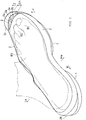
FIG. 1 is a schematic perspective view showing a sole according toEmbodiment 1 of the present invention. -
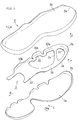
FIG. 2 is a perspective view showing a midsole and a reinforcement plate of the sole, as seen from the bottom side. -
FIG. 3 is an exploded perspective view of the sole. -
FIG. 4 is a perspective view of a reinforcement plate. -
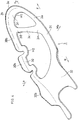
FIG. 5 is a plan view showing a relationship between a reinforcement plate and the foot bone structure. -
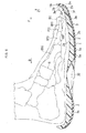
FIG. 6 is a medial side view of a reinforcement plate, showing a midsole and an outsole, partly in a cross-sectional view. -
FIG. 7A is a characteristic diagram showing a relationship between the vertical reaction force from the floor surface during a jump and the jump efficiency, andFIG. 7B is a characteristic diagram showing a relationship between the jump efficiency and the jump height. -
FIG. 8 is a schematic perspective view showing a sole according toEmbodiment 2. -
FIG. 9A, FIG. 9B and FIG. 9C are plan views showing reinforcement plates according to other embodiments. - Preferably, at the front end portion of the mid sole, the roll-up portion projects upwardly by 0.3 cm to 3.0 cm with respect to the upper surface of the mid sole.
- If the projection height of the roll-up portion is less than 0.3 cm, the advantageous effect set forth above will be insufficient, whereas if the projection height exceeds 3.0 cm, the rigidity of the toe of the shoe will be excessive.
- For such reasons, the projection height is set more preferably to 0.4 cm to 2.0 cm, and most preferably to 0.4 cm to 1.5 cm.
- Preferably, a position of an upper end of the roll-up portion covering an anterior of a distal phalanx of the big toe is set to be below an upper surface of a base of the distal phalanx of the big toe.
- In such a case, it is possible to prevent the rigidity of the toe from becoming excessive. Note that the roll-up portion covering the distal phalanx may have openings (through holes) or cutouts.
- Preferably, the base plate portion continuously extends to posterior of metatarsal phalangeal joints (MP joints) of the big toe and the little toe.
- In such a case, it is possible to reduce excessive extension of the MP joints, and it can be expected that the impulse increases due to restoration of the reinforcement plate having been bent at the MP joints.
- More preferably, the reinforcement plate further integrally includes a connecting bar connecting together a medial side and a lateral side of the base plate portion, and a medial side end of the connecting bar is arranged posterior to a lateral side end thereof, and the connecting bar extends anterior as the connecting bar extends toward a lateral side.
- In such a case, the connecting bar extends in a direction crossing the array of MP joints of the foot. Therefore, it is possible to further reduce excessive extension of the MP joints.
- Preferably, the base plate portion extends to posterior of a Lisfranc joint on the medial side and the lateral side of the foot.
- In such a case, the extension of the foot at the MP joints is further reduced, and it can be expected that the jump height increases.
- Preferably, the anti-slip member covers the roll-up portion from a lower end to an upper end thereof. In such a case, the resin roll-up portion will not come into contact with the floor surface, and it is therefore possible to reliably reduce the slip.
- Note however that the anti-slip member does not need to cover the entire surface of the roll-up portion, but openings (through holes) may be provided in the anti-slip member so that the reinforcement plate is slightly visible from the front side.
- Preferably, the base plate portion includes a lateral edge portion extending from the front portion in a posterior direction so as to cover a lateral edge of the mid sole, a lateral roll-up portion rolled up upwardly from the lateral edge portion, and a medial side portion spaced apart from a medial edge of the mid sole and extending from the front portion to posterior of a ball of the big toe along the medial edge so as to cover at least a portion of the big toe.
- In such a case, the medial side portion of the base portion extending along the big toe assists the flexion of the MP joint of the big toe having been extended during a jump, thereby increasing the jump height.
- On the other hand, the lateral edge portion and the lateral roll-up portion extending along the lateral edge of the midsole not only assist the flexion on the little toe side, but also reduce the shifting of the foot toward the lateral side during landing or receiving.
- The present invention will be understood more clearly from the following description of preferred embodiments taken in conjunction with the accompanying documents. Note however that the embodiments and the drawings are merely illustrative and should not be taken to define the scope of the present invention. The scope of the present invention shall be defined only by the appended claims. In the accompanying drawings, like reference numerals denote like components throughout the plurality of figures.
- Embodiments of the present invention will now be described with reference to the drawings.
-
FIG. 1 to FIG. 6 show Embodiment 1. Note that the figures do not show the upper of the shoe. - The present embodiment is, for example, a shoe for volleyball.
- The sole shown in
FIG. 1 includes anoutsole 1, amidsole 2 and areinforcement plate 3 integrally layered together via bonding or welding. - The
outsole 1 shown inFIG. 6 is formed by a foamed material or a non-foamed material of a rubber, and has a greater frictional force on the floor surface than themidsole 2 and thereinforcement plate 3. Theoutsole 1 includes atread surface 1s to be in contact with the floor surface, and a roll-up portion at the front end forming ananti-slip member 1b to be described later. - The
midsole 2 is arranged upward Z of theoutsole 1, and covers the entire area of the sole of the foot. Themidsole 2 is formed mainly by a foamed material having a thermoplastic resin component such as EVA, for example, and absorbs the impact of landing. Note that as shown inFIG. 1 , a portion of themidsole 2 may have a rubber-likeelastic shock absorber 29, etc. - An insole (inner sole) (not shown) is bonded on the
midsole 2. A sock liner is further attached on the insole in an upper (not shown). Note that an upper is for covering and wrapping the instep of the foot. - In
FIG. 3 andFIG. 6 , thereinforcement plate 3 is formed by a non-foamed material containing a thermoplastic resin component, and has a Young's modulus greater than the Young's modulus of theoutsole 1 and the Young's modulus of themidsole 2. - Note that the preferred Young's modulus value of the
reinforcement plate 3 is 20 to 500 Mpa, more preferably 40 to 200 Mpa. - The
reinforcement plate 3 is arranged between theoutsole 1 and themidsole 2. In the present embodiment, thereinforcement plate 3 is sandwiched between anupper surface 1a of theoutsole 1 and alower surface 2b of themidsole 2. Note that where themidsole 2 includes two, upper and lower, layers layered together, thereinforcement plate 3 may be arranged between the upper and lower layers of themidsole 2. Therefore, there is no particular limitation as long as thereinforcement plate 3 is arranged between theoutsole 1 and themidsole 2. - In
FIG. 5 , B1 denotes the big toe, B2 the second toe, and B5 the little toe. B11, B21 and B51 denote their respective distal phalanges, B13, B23 and B53 their respective proximal phalanges, and B14, B24 and B54 their respective metatarsal bones. - The
reinforcement plate 3 includes abase portion 3a, a front roll-upportion 3b, a connectingbar 3c, alateral edge portion 30, amedial side portion 31 and ashank portion 32, which are provided as a loop-shaped integral part. Thereinforcement plate 3 does not cover the toes including the big toe B1 and the little toe B5 from directly above. - The
base portion 3a extends from posterior B of the heads of the proximal phalanges B13 and B53 of the big toe B1 and the little toe B5 to anterior F of the tip of the foot. Afront portion 3f of thereinforcement plate 3 is curved, and continuously extends from the medial side Me toward the lateral side La. - Note that a head refers to a portion of each bone that is close to the anterior joint and that is slightly expanding to a greater thickness and it is referred to also as a distal head. On the other hand, a base refers to a portion of each bone that is close to the posterior joint and that is slightly expanding to a greater thickness and it is referred to also as a proximal head.
- As shown in
FIG. 6 , the front roll-upportion 3b is integrally continuous with thefront portion 3f of thebase portion 3a, and extends to anterior F of the front end of themidsole 2 while projecting, from thefront portion 3f, upward Z of anupper surface 2a of afront end portion 2e of themidsole 2. Moreover, the front roll-upportion 3b is rolled up upward Z, and covers the anterior F of the big toe B1 as shown inFIG. 1 . That is, the front roll-upportion 3b extends along themidsole 2 toward an upper-forward diagonal direction past the front end of themidsole 2, and projects from theupper surface 2a at the front end of themidsole 2 in a crescent shape or a half-moon shape. - Note that a portion of the front roll-up
portion 3b that is projecting upward Z from themidsole 2 is dotted. - In the present embodiment, the front roll-up
portion 3b is covered, from the lower end to the upper end of the front roll-upportion 3b, with theanti-slip member 1b of theoutsole 1, as shown inFIG. 1 andFIG. 6 . Note that the front roll-upportion 3b and theanti-slip member 1b cover the toe portion of the upper (not shown). - However, there is no particular limitation in the present invention as long as at least a portion of a
front surface 3s of the front roll-upportion 3b ofFIG. 2 is covered by theanti-slip member 1b ofFIG. 1 having a greater frictional force on the floor surface than thereinforcement plate 3. For example, theanti-slip member 1b may be separate from theoutsole 1. Small through holes or cutouts may be provided in theanti-slip member 1b so that the front roll-upportion 3b is partly visible from the front side. - Preferably, in the
front end portion 2e of themidsole 2, the front roll-upportion 3b is projecting upwardly by 0.3 cm to 3.0 cm with respect to theupper surface 2a of themidsole 2 as shown inFIG. 6 . More preferably, the amount of projection ΔH is 0.4 cm to 2.0 cm. - Preferably, the position of the upper end of the front roll-up
portion 3b covering the distal phalanx B11 of the big toe B1 is set to be below an upper surface F11 of the base of the distal phalanx B11 of the big toe B1. - As shown in
FIG. 5 , in the present embodiment, thebase portion 3a continuously extends to posterior B of the metatarsal phalangeal joints MP of the big toe B1 and the little toe B5. Moreover, thebase portion 3a extends to posterior B of the Lisfranc joint R on the medial side Me and the lateral side La of the foot. - The
base portion 3a includes thelateral edge portion 30, a lateral roll-upportion 30b, themedial side portion 31 and theshank portion 32 as an integral part. - The
lateral edge portion 30 ofFIG. 2 extends toward the posterior B direction from thefront portion 3f so as to cover a lateral edge 21 of themidsole 2. The lateral roll-upportion 30b is rolled up upward Z from thelateral edge portion 30. Themedial side portion 31 is spaced apart from amedial edge 2m of themidsole 2, and extends from thefront portion 3f along themedial edge 2m to posterior B of the ball BO of the big toe ofFIG. 5 , covering at least a portion of the big toe B1. - Thus, the
base portion 3a of thereinforcement plate 3 is formed in a continuous loop shape extending from thefront portion 3f and the front roll-upportion 3b to theshank portion 32 via thelateral edge portion 30 and themedial side portion 31. Note that theshank portion 32 reinforces the arch, as is well known in the art. - The
reinforcement plate 3 further integrally includes the connectingbar 3c connecting together the medial side Me and the lateral side La of thebase portion 3a. Amedial end 3m of the connectingbar 3c is arranged posterior B to alateral end 31 thereof. Thus, the connectingbar 3c extends anterior F as it extends toward the lateral side La. - The connecting
bar 3c defines two through holes H1 and H2 in the loop-shapedreinforcement plate 3. - The connecting
bar 3c will reduce excessive extension of the MP joints MP from the second toe B2 to the little toe B5. - Next, the mechanism of a jump when spiking in volleyball, etc., will be described.
- For a right-footed player, for example, starting with both feet on the ground, both knees are bent, and then the MP joints are extended while extending the knees, thereby first lifting the right foot in the air, and then lifting the left foot in the art.
-
FIG. 7A shows the results of a test on the relationship between the floor reaction force Fz and the jump efficiency ∑Fz, andFIG. 7B shows the results of a test on the relationship between the jump efficiency ∑Fz and the jump height. - The jump efficiency ∑Fz which is dotted in
FIG. 7A , i.e., the impulse ∑Fz from when the floor reaction force Fz peaks until the foot comes completely off the floor, is speculated to have a strong correlation with the jump height as shown inFIG. 7B . - Now, at the moment a foot comes off the ground, the MP joint remains extended while the toes anterior thereto kicks the floor surface. If it is made easier to exert power at the toes and kick the floor surface immediately before the take-off, the impulse ∑Fz will be the primary area α1 (dotted) plus the additional area α2 (hatched). This will increase the jump height.
- Moreover, if the extended MP joint is flexed immediately before the take-off, it will further increase the additional area α2, thereby further increasing the jump height.
- In this example, the upper portion of the front roll-up
portion 3b is exposed from theanti-slip member 1b, which is a roll-up portion of theoutsole 1. In this example, the exposed front roll-upportion 3b is large, and it will further increase the jump height when spiking. - Note that a test conducted for the increase of the jump height by using
Embodiment 2 showed an increase of the jump height of about 2.5 cm. - In the example of
FIG. 9A , the connectingbar 3c is absent. - In the example of
FIG. 9B , thefront portion 3f of thereinforcement plate 3 is formed in a half-moon shape. - In the example of
FIG. 9C , no opening is provided in thereinforcement plate 3 from thefront portion 3f to theshank portion 32. - While preferred embodiments have been described above with reference to the drawings, various obvious changes and modifications will readily occur to those skilled in the art upon reading the present specification.
- For example, the
reinforcement plate 3 ofFIG. 5 may be provided extending from the front roll-upportion 3b to posterior B of the heads of the proximal phalanges B13 and B53 of the big toe B1 and the little toe B5, and may be absent posterior B to the heads. - Alternatively, the
reinforcement plate 3 may be provided in a U-letter shape extending from the front roll-upportion 3b to posterior B of the heads of the metatarsal bone B14 and B54 of the big toe B1 and the little toe B5, and may be absent posterior B to the heads. - In such cases, it is preferably provided with the
lateral edge portion 30 and themedial side portion 31 extending toward the anterior F direction from theshank portion 32, with the front end portions of thelateral edge portion 30 and themedial side portion 31 overlapping the rear end portion of thebase portion 3a of thereinforcement plate 3 over a portion of the foot in the long axis direction. - The
reinforcement plate 3 may be provided as an integral part of themidsole 2 in the post molding (secondary molding process) of themidsole 2. - The subject structure may be provided only for the left foot or the right foot, but it may be provided for both of the left foot and the right foot.
- Thus, such changes and modifications are deemed to fall within the scope of the present invention.
- The present invention is applicable to shoes for indoor sports such as volleyball.
-
- 1:
Outsole 1a:Upper surface 1b: Anti-slip member Is: Tread surface - 2:
Midsole 2a:Upper surface 2b:Lower surface 2e: Front end portion 21:Lateral edge 2m: Medial edge - 3: Reinforcement plate 30:
Lateral edge portion 30b: Lateral roll-up portion 31: Medial side portion 32:Shank portion 3a:Base portion 3b: (Front) roll-upportion 3c: connectingbar 3e:Upper end 3f:Front portion 3s: Front surface 31:Lateral end 3m: Medial end - B1: Big toe B11: Distal phalanx B13: Proximal phalanx B14: Metatarsal bone
- B2: Second toe B21: Distal phalanx B23: Proximal phalanx B24: Metatarsal bone
- B5: Little toe B51: Distal phalanx B53: Proximal phalanx B54: Metatarsal bone
- BO: Ball of big toe
- MP: Metatarsal phalangeal joint R: Lisfranc joint
- Me: Medial side La: Lateral side
- F: Anterior B: Posterior Z: Upward
- ΔH: Amount of projection
Claims (8)
- A shoe for indoor sports comprising:an outer sole (1) having a tread surface;a mid sole (2) arranged over the outer sole (1); anda resin reinforcement plate (3) which has a Young's modulus greater than a Young's modulus of the outer sole (1) and than a Young's modulus of the mid sole (2) and which is arranged between the outer sole (1) and the mid sole (2), characterized in that:the reinforcement plate (3) includes a base plate portion (3a) and a roll-up portion (3b) formed integrally continuous together, with the base plate portion (3a) extending from posterior (B) of heads of proximal phalanges (B53) of a big toe (B1) and a little toe (B5) to anterior (F) of a tip of a foot, and extending continuously from a medial side (Me) toward a lateral side (La) in a front portion (3f) of the reinforcement plate (3), and with the roll-up portion (3b) being rolled up from the front portion (3f) of the base plate portion (3a) upwardly (Z) above an upper surface (2a) of a front end portion (2e) of the mid sole (2) so as to cover an anterior (F) of the big toe (B1), and the reinforcement plate (3) does not cover toes including the big toe (B1) and the little toe (B5) from directly above; andat least a portion of a front surface (3s) of the roll-up portion (3b) is covered by an anti-slip member (1b) having a greater frictional force against a floor surface than the reinforcement plate (3).
- A shoe according to claim 1, wherein at a front end portion (2e) of the mid sole (2), the roll-up portion (3b) projects upwardly by 0.3 cm to 3.0 cm with respect to the upper surface (2a) of the mid sole (2).
- A shoe according to claim 1, wherein a position of an upper end of the roll-up portion (3b) covering an anterior (F) of a distal phalanx (B11) of the big toe (B1) is set to be below an upper surface of a base of the distal phalanx (B11) of the big toe (B1).
- A shoe according to claim 1, 2 or 3, wherein the base plate portion (3a) continuously extends to posterior (B) of metatarsal phalangeal joints (MP) of the big toe (B1) and the little toe (B5).
- A shoe according to claim 4, wherein the reinforcement plate (3) further integrally includes a connecting bar (3c) connecting together a medial side (Me) Me-and a lateral side (La) of the base plate portion (3a), and a medial side end (3m) of the connecting bar (3c) is arranged posterior (B) to a lateral side end (31) thereof, and the connecting bar (3c) extends anterior (F) as the connecting bar (3c) extends toward a lateral side (La).
- A shoe according to any one of claims 1 to 5, wherein the base plate portion (3a) extends to posterior (B) of a Lisfranc joint (R) on the medial side (Me) and the lateral side (La) of the foot.
- A shoe according to any one of claims 1 to 6, wherein the anti-slip member (1b) covers the roll-up portion (3b) from a lower end to an upper end thereof.
- A shoe according to any one of claims 1 to 7, wherein the base plate portion (3a) includes a lateral edge portion (30) extending from the front portion (3f) in a posterior (B) direction so as to cover a lateral edge (21) of the mid sole (2), a lateral roll-up portion (30b) rolled up upwardly (Z) from the lateral edge portion (30), and a medial side portion (31) spaced apart from a medial edge (2m) of the mid sole (2) and extending from the front portion (3f) to posterior (B) of a ball (BO) of the big toe along the medial edge (2m) so as to cover at least a portion of the big toe (B1).
Applications Claiming Priority (1)
| Application Number | Priority Date | Filing Date | Title |
|---|---|---|---|
| PCT/JP2013/058730 WO2014155511A1 (en) | 2013-03-26 | 2013-03-26 | Shoe for indoor sports |
Publications (3)
| Publication Number | Publication Date |
|---|---|
| EP2979568A1 EP2979568A1 (en) | 2016-02-03 |
| EP2979568A4 EP2979568A4 (en) | 2016-11-30 |
| EP2979568B1 true EP2979568B1 (en) | 2018-05-02 |
Family
ID=51622599
Family Applications (1)
| Application Number | Title | Priority Date | Filing Date |
|---|---|---|---|
| EP13880141.0A Active EP2979568B1 (en) | 2013-03-26 | 2013-03-26 | Shoe for indoor sports |
Country Status (3)
| Country | Link |
|---|---|
| EP (1) | EP2979568B1 (en) |
| JP (1) | JP5649151B1 (en) |
| WO (1) | WO2014155511A1 (en) |
Families Citing this family (14)
| Publication number | Priority date | Publication date | Assignee | Title |
|---|---|---|---|---|
| DE102015206486B4 (en) * | 2015-04-10 | 2023-06-01 | Adidas Ag | Shoe, in particular sports shoe, and method for manufacturing the same |
| JP6786595B2 (en) | 2015-10-02 | 2020-11-18 | ナイキ イノベイト シーブイ | Board with foam for footwear |
| CN113558345B (en) * | 2015-10-02 | 2023-09-29 | 耐克创新有限合伙公司 | Foam board for footwear |
| MX2018004048A (en) | 2015-10-02 | 2019-01-24 | Nike Innovate Cv | Plate for footwear. |
| EP3355737B1 (en) * | 2015-10-02 | 2022-03-30 | Nike Innovate C.V. | Plate for footwear |
| CN115413855A (en) | 2016-07-20 | 2022-12-02 | 耐克创新有限合伙公司 | Shoe plate |
| CN113876073A (en) | 2017-05-23 | 2022-01-04 | 耐克创新有限合伙公司 | Sole structure for an article of footwear with a contoured sole plate |
| CN110868882B (en) | 2018-04-16 | 2021-09-21 | 耐克创新有限合伙公司 | Shoe outer sole plate |
| US11344078B2 (en) | 2018-04-16 | 2022-05-31 | Nike, Inc. | Outsole plate |
| EP3801105B1 (en) | 2018-05-31 | 2024-01-24 | NIKE Innovate C.V. | Footwear sole plate with forefoot through hole |
| US11089834B2 (en) | 2018-05-31 | 2021-08-17 | Nike, Inc. | Footwear sole plate with non-parallel waves of varying thickness |
| AU2018455872A1 (en) * | 2018-12-28 | 2021-07-22 | Asics Corporation | Shoe |
| CN112545105A (en) * | 2020-12-07 | 2021-03-26 | 革乐美时尚有限公司 | Health shoes |
| JP2022175847A (en) * | 2021-05-14 | 2022-11-25 | 株式会社アシックス | Sole and shoe |
Family Cites Families (12)
| Publication number | Priority date | Publication date | Assignee | Title |
|---|---|---|---|---|
| JPS57186509U (en) | 1981-05-22 | 1982-11-26 | ||
| US4412393A (en) | 1981-07-10 | 1983-11-01 | Ballet Makers, Inc. | Ballet toe shoe and process of manufacture thereof |
| US4453996A (en) | 1981-07-10 | 1984-06-12 | Ballet Makers, Inc. | Process of making a ballet toe shoe |
| JPS59103605U (en) * | 1982-12-28 | 1984-07-12 | 美津濃株式会社 | athletic shoe soles |
| US6470599B1 (en) * | 2001-04-23 | 2002-10-29 | Young Chu | Climbing shoe with concave sole |
| JP2002360305A (en) | 2001-06-13 | 2002-12-17 | Mizuno Corp | Sole structure of shoe |
| US7299567B2 (en) * | 2004-06-17 | 2007-11-27 | Nike, Inc. | Article of footwear with sole plate |
| KR200401548Y1 (en) * | 2005-09-08 | 2005-11-21 | 장소정 | Ballet boots |
| JP4851781B2 (en) * | 2005-11-17 | 2012-01-11 | 株式会社アシックス | Shoe with lateral vibration suppression function |
| FR2898252B1 (en) * | 2006-03-07 | 2008-07-04 | Salomon Sa | SHOE AND ITS SEMELAGE |
| EP2540183A3 (en) | 2006-10-20 | 2013-07-10 | ASICS Corporation | Structure for front foot portion of a shoe sole |
| WO2009066361A1 (en) | 2007-11-19 | 2009-05-28 | Asics Corporation | Shoe having peeling prevention structure of wind-up portion |
-
2013
- 2013-03-26 JP JP2014511677A patent/JP5649151B1/en active Active
- 2013-03-26 EP EP13880141.0A patent/EP2979568B1/en active Active
- 2013-03-26 WO PCT/JP2013/058730 patent/WO2014155511A1/en active Application Filing
Non-Patent Citations (1)
| Title |
|---|
| None * |
Also Published As
| Publication number | Publication date |
|---|---|
| EP2979568A1 (en) | 2016-02-03 |
| EP2979568A4 (en) | 2016-11-30 |
| WO2014155511A1 (en) | 2014-10-02 |
| JPWO2014155511A1 (en) | 2017-02-16 |
| JP5649151B1 (en) | 2015-01-07 |
Similar Documents
| Publication | Publication Date | Title |
|---|---|---|
| EP2979568B1 (en) | Shoe for indoor sports | |
| US12075888B2 (en) | Article of footwear with medial contact portion | |
| US11744324B2 (en) | Article of footwear with multiple durometer outsole | |
| EP3777593B1 (en) | Shoe sole including laminate-structured midsole | |
| JP6454784B2 (en) | A shoe having a sole with a forefoot divided | |
| EP2499926B1 (en) | Article of footwear comprising a sole structure | |
| US9775402B2 (en) | Shoe sole having outsole and midsole | |
| US9788602B2 (en) | Basketball insole | |
| US9661896B2 (en) | Shoe with elastically flexible extension | |
| WO2016208062A1 (en) | Shoe having sole having divided hind foot section | |
| EP3222161A1 (en) | Improved heelless athletic shoe | |
| WO2017110440A1 (en) | Outsole structure for shoes and cleated shoe using same | |
| JP2008012203A (en) | Sockliner and insole | |
| KR20210018435A (en) | Shoe insole | |
| US20070062065A1 (en) | Shoe sole with energy return plate | |
| JP7142345B2 (en) | Insoles for light mountaineering | |
| EP3056105A1 (en) | Exercise shoe sole | |
| JP2016055030A (en) | Shoe sock liner | |
| CN113260272B (en) | Shoes with removable sole | |
| JP4856658B2 (en) | Insoles | |
| JP2004254803A (en) | Insole structure | |
| CN115666308A (en) | Sole and shoe |
Legal Events
| Date | Code | Title | Description |
|---|---|---|---|
| PUAI | Public reference made under article 153(3) epc to a published international application that has entered the european phase |
Free format text: ORIGINAL CODE: 0009012 |
|
| 17P | Request for examination filed |
Effective date: 20151026 |
|
| AK | Designated contracting states |
Kind code of ref document: A1 Designated state(s): AL AT BE BG CH CY CZ DE DK EE ES FI FR GB GR HR HU IE IS IT LI LT LU LV MC MK MT NL NO PL PT RO RS SE SI SK SM TR |
|
| AX | Request for extension of the european patent |
Extension state: BA ME |
|
| DAX | Request for extension of the european patent (deleted) | ||
| A4 | Supplementary search report drawn up and despatched |
Effective date: 20161031 |
|
| RIC1 | Information provided on ipc code assigned before grant |
Ipc: A43B 13/41 20060101AFI20161025BHEP Ipc: A43B 13/18 20060101ALI20161025BHEP Ipc: A43B 13/02 20060101ALI20161025BHEP |
|
| RIC1 | Information provided on ipc code assigned before grant |
Ipc: A43B 13/41 20060101AFI20170904BHEP Ipc: A43B 13/02 20060101ALI20170904BHEP Ipc: A43B 13/18 20060101ALI20170904BHEP |
|
| GRAP | Despatch of communication of intention to grant a patent |
Free format text: ORIGINAL CODE: EPIDOSNIGR1 |
|
| STAA | Information on the status of an ep patent application or granted ep patent |
Free format text: STATUS: GRANT OF PATENT IS INTENDED |
|
| INTG | Intention to grant announced |
Effective date: 20171030 |
|
| GRAS | Grant fee paid |
Free format text: ORIGINAL CODE: EPIDOSNIGR3 |
|
| GRAA | (expected) grant |
Free format text: ORIGINAL CODE: 0009210 |
|
| STAA | Information on the status of an ep patent application or granted ep patent |
Free format text: STATUS: THE PATENT HAS BEEN GRANTED |
|
| AK | Designated contracting states |
Kind code of ref document: B1 Designated state(s): AL AT BE BG CH CY CZ DE DK EE ES FI FR GB GR HR HU IE IS IT LI LT LU LV MC MK MT NL NO PL PT RO RS SE SI SK SM TR |
|
| REG | Reference to a national code |
Ref country code: GB Ref legal event code: FG4D Ref country code: DE Ref legal event code: R082 Ref document number: 602013037095 Country of ref document: DE Representative=s name: VOSSIUS & PARTNER PATENTANWAELTE RECHTSANWAELT, DE |
|
| REG | Reference to a national code |
Ref country code: CH Ref legal event code: EP Ref country code: AT Ref legal event code: REF Ref document number: 994300 Country of ref document: AT Kind code of ref document: T Effective date: 20180515 |
|
| REG | Reference to a national code |
Ref country code: IE Ref legal event code: FG4D |
|
| REG | Reference to a national code |
Ref country code: DE Ref legal event code: R096 Ref document number: 602013037095 Country of ref document: DE |
|
| REG | Reference to a national code |
Ref country code: NL Ref legal event code: MP Effective date: 20180502 |
|
| REG | Reference to a national code |
Ref country code: LT Ref legal event code: MG4D |
|
| PG25 | Lapsed in a contracting state [announced via postgrant information from national office to epo] |
Ref country code: FI Free format text: LAPSE BECAUSE OF FAILURE TO SUBMIT A TRANSLATION OF THE DESCRIPTION OR TO PAY THE FEE WITHIN THE PRESCRIBED TIME-LIMIT Effective date: 20180502 Ref country code: BG Free format text: LAPSE BECAUSE OF FAILURE TO SUBMIT A TRANSLATION OF THE DESCRIPTION OR TO PAY THE FEE WITHIN THE PRESCRIBED TIME-LIMIT Effective date: 20180802 Ref country code: LT Free format text: LAPSE BECAUSE OF FAILURE TO SUBMIT A TRANSLATION OF THE DESCRIPTION OR TO PAY THE FEE WITHIN THE PRESCRIBED TIME-LIMIT Effective date: 20180502 Ref country code: SE Free format text: LAPSE BECAUSE OF FAILURE TO SUBMIT A TRANSLATION OF THE DESCRIPTION OR TO PAY THE FEE WITHIN THE PRESCRIBED TIME-LIMIT Effective date: 20180502 Ref country code: NO Free format text: LAPSE BECAUSE OF FAILURE TO SUBMIT A TRANSLATION OF THE DESCRIPTION OR TO PAY THE FEE WITHIN THE PRESCRIBED TIME-LIMIT Effective date: 20180802 Ref country code: ES Free format text: LAPSE BECAUSE OF FAILURE TO SUBMIT A TRANSLATION OF THE DESCRIPTION OR TO PAY THE FEE WITHIN THE PRESCRIBED TIME-LIMIT Effective date: 20180502 |
|
| PG25 | Lapsed in a contracting state [announced via postgrant information from national office to epo] |
Ref country code: HR Free format text: LAPSE BECAUSE OF FAILURE TO SUBMIT A TRANSLATION OF THE DESCRIPTION OR TO PAY THE FEE WITHIN THE PRESCRIBED TIME-LIMIT Effective date: 20180502 Ref country code: RS Free format text: LAPSE BECAUSE OF FAILURE TO SUBMIT A TRANSLATION OF THE DESCRIPTION OR TO PAY THE FEE WITHIN THE PRESCRIBED TIME-LIMIT Effective date: 20180502 Ref country code: NL Free format text: LAPSE BECAUSE OF FAILURE TO SUBMIT A TRANSLATION OF THE DESCRIPTION OR TO PAY THE FEE WITHIN THE PRESCRIBED TIME-LIMIT Effective date: 20180502 Ref country code: LV Free format text: LAPSE BECAUSE OF FAILURE TO SUBMIT A TRANSLATION OF THE DESCRIPTION OR TO PAY THE FEE WITHIN THE PRESCRIBED TIME-LIMIT Effective date: 20180502 Ref country code: GR Free format text: LAPSE BECAUSE OF FAILURE TO SUBMIT A TRANSLATION OF THE DESCRIPTION OR TO PAY THE FEE WITHIN THE PRESCRIBED TIME-LIMIT Effective date: 20180803 |
|
| REG | Reference to a national code |
Ref country code: AT Ref legal event code: MK05 Ref document number: 994300 Country of ref document: AT Kind code of ref document: T Effective date: 20180502 |
|
| PG25 | Lapsed in a contracting state [announced via postgrant information from national office to epo] |
Ref country code: SK Free format text: LAPSE BECAUSE OF FAILURE TO SUBMIT A TRANSLATION OF THE DESCRIPTION OR TO PAY THE FEE WITHIN THE PRESCRIBED TIME-LIMIT Effective date: 20180502 Ref country code: PL Free format text: LAPSE BECAUSE OF FAILURE TO SUBMIT A TRANSLATION OF THE DESCRIPTION OR TO PAY THE FEE WITHIN THE PRESCRIBED TIME-LIMIT Effective date: 20180502 Ref country code: EE Free format text: LAPSE BECAUSE OF FAILURE TO SUBMIT A TRANSLATION OF THE DESCRIPTION OR TO PAY THE FEE WITHIN THE PRESCRIBED TIME-LIMIT Effective date: 20180502 Ref country code: RO Free format text: LAPSE BECAUSE OF FAILURE TO SUBMIT A TRANSLATION OF THE DESCRIPTION OR TO PAY THE FEE WITHIN THE PRESCRIBED TIME-LIMIT Effective date: 20180502 Ref country code: CZ Free format text: LAPSE BECAUSE OF FAILURE TO SUBMIT A TRANSLATION OF THE DESCRIPTION OR TO PAY THE FEE WITHIN THE PRESCRIBED TIME-LIMIT Effective date: 20180502 Ref country code: AT Free format text: LAPSE BECAUSE OF FAILURE TO SUBMIT A TRANSLATION OF THE DESCRIPTION OR TO PAY THE FEE WITHIN THE PRESCRIBED TIME-LIMIT Effective date: 20180502 Ref country code: DK Free format text: LAPSE BECAUSE OF FAILURE TO SUBMIT A TRANSLATION OF THE DESCRIPTION OR TO PAY THE FEE WITHIN THE PRESCRIBED TIME-LIMIT Effective date: 20180502 |
|
| REG | Reference to a national code |
Ref country code: DE Ref legal event code: R097 Ref document number: 602013037095 Country of ref document: DE |
|
| PG25 | Lapsed in a contracting state [announced via postgrant information from national office to epo] |
Ref country code: IT Free format text: LAPSE BECAUSE OF FAILURE TO SUBMIT A TRANSLATION OF THE DESCRIPTION OR TO PAY THE FEE WITHIN THE PRESCRIBED TIME-LIMIT Effective date: 20180502 Ref country code: SM Free format text: LAPSE BECAUSE OF FAILURE TO SUBMIT A TRANSLATION OF THE DESCRIPTION OR TO PAY THE FEE WITHIN THE PRESCRIBED TIME-LIMIT Effective date: 20180502 |
|
| PLBE | No opposition filed within time limit |
Free format text: ORIGINAL CODE: 0009261 |
|
| STAA | Information on the status of an ep patent application or granted ep patent |
Free format text: STATUS: NO OPPOSITION FILED WITHIN TIME LIMIT |
|
| 26N | No opposition filed |
Effective date: 20190205 |
|
| PG25 | Lapsed in a contracting state [announced via postgrant information from national office to epo] |
Ref country code: SI Free format text: LAPSE BECAUSE OF FAILURE TO SUBMIT A TRANSLATION OF THE DESCRIPTION OR TO PAY THE FEE WITHIN THE PRESCRIBED TIME-LIMIT Effective date: 20180502 |
|
| PG25 | Lapsed in a contracting state [announced via postgrant information from national office to epo] |
Ref country code: MC Free format text: LAPSE BECAUSE OF FAILURE TO SUBMIT A TRANSLATION OF THE DESCRIPTION OR TO PAY THE FEE WITHIN THE PRESCRIBED TIME-LIMIT Effective date: 20180502 |
|
| REG | Reference to a national code |
Ref country code: CH Ref legal event code: PL |
|
| GBPC | Gb: european patent ceased through non-payment of renewal fee |
Effective date: 20190326 |
|
| PG25 | Lapsed in a contracting state [announced via postgrant information from national office to epo] |
Ref country code: AL Free format text: LAPSE BECAUSE OF FAILURE TO SUBMIT A TRANSLATION OF THE DESCRIPTION OR TO PAY THE FEE WITHIN THE PRESCRIBED TIME-LIMIT Effective date: 20180502 Ref country code: LU Free format text: LAPSE BECAUSE OF NON-PAYMENT OF DUE FEES Effective date: 20190326 |
|
| REG | Reference to a national code |
Ref country code: BE Ref legal event code: MM Effective date: 20190331 |
|
| PG25 | Lapsed in a contracting state [announced via postgrant information from national office to epo] |
Ref country code: IE Free format text: LAPSE BECAUSE OF NON-PAYMENT OF DUE FEES Effective date: 20190326 Ref country code: CH Free format text: LAPSE BECAUSE OF NON-PAYMENT OF DUE FEES Effective date: 20190331 Ref country code: GB Free format text: LAPSE BECAUSE OF NON-PAYMENT OF DUE FEES Effective date: 20190326 Ref country code: LI Free format text: LAPSE BECAUSE OF NON-PAYMENT OF DUE FEES Effective date: 20190331 |
|
| PG25 | Lapsed in a contracting state [announced via postgrant information from national office to epo] |
Ref country code: BE Free format text: LAPSE BECAUSE OF NON-PAYMENT OF DUE FEES Effective date: 20190331 |
|
| PG25 | Lapsed in a contracting state [announced via postgrant information from national office to epo] |
Ref country code: TR Free format text: LAPSE BECAUSE OF FAILURE TO SUBMIT A TRANSLATION OF THE DESCRIPTION OR TO PAY THE FEE WITHIN THE PRESCRIBED TIME-LIMIT Effective date: 20180502 |
|
| PG25 | Lapsed in a contracting state [announced via postgrant information from national office to epo] |
Ref country code: MT Free format text: LAPSE BECAUSE OF NON-PAYMENT OF DUE FEES Effective date: 20190326 Ref country code: PT Free format text: LAPSE BECAUSE OF FAILURE TO SUBMIT A TRANSLATION OF THE DESCRIPTION OR TO PAY THE FEE WITHIN THE PRESCRIBED TIME-LIMIT Effective date: 20180903 |
|
| PG25 | Lapsed in a contracting state [announced via postgrant information from national office to epo] |
Ref country code: CY Free format text: LAPSE BECAUSE OF FAILURE TO SUBMIT A TRANSLATION OF THE DESCRIPTION OR TO PAY THE FEE WITHIN THE PRESCRIBED TIME-LIMIT Effective date: 20180502 |
|
| PG25 | Lapsed in a contracting state [announced via postgrant information from national office to epo] |
Ref country code: IS Free format text: LAPSE BECAUSE OF FAILURE TO SUBMIT A TRANSLATION OF THE DESCRIPTION OR TO PAY THE FEE WITHIN THE PRESCRIBED TIME-LIMIT Effective date: 20180902 |
|
| PG25 | Lapsed in a contracting state [announced via postgrant information from national office to epo] |
Ref country code: HU Free format text: LAPSE BECAUSE OF FAILURE TO SUBMIT A TRANSLATION OF THE DESCRIPTION OR TO PAY THE FEE WITHIN THE PRESCRIBED TIME-LIMIT; INVALID AB INITIO Effective date: 20130326 |
|
| PG25 | Lapsed in a contracting state [announced via postgrant information from national office to epo] |
Ref country code: MK Free format text: LAPSE BECAUSE OF FAILURE TO SUBMIT A TRANSLATION OF THE DESCRIPTION OR TO PAY THE FEE WITHIN THE PRESCRIBED TIME-LIMIT Effective date: 20180502 |
|
| PGFP | Annual fee paid to national office [announced via postgrant information from national office to epo] |
Ref country code: DE Payment date: 20240130 Year of fee payment: 12 |
|
| PGFP | Annual fee paid to national office [announced via postgrant information from national office to epo] |
Ref country code: FR Payment date: 20240213 Year of fee payment: 12 |