CN115666308A - Sole and shoe - Google Patents
Sole and shoe Download PDFInfo
- Publication number
- CN115666308A CN115666308A CN202080101432.5A CN202080101432A CN115666308A CN 115666308 A CN115666308 A CN 115666308A CN 202080101432 A CN202080101432 A CN 202080101432A CN 115666308 A CN115666308 A CN 115666308A
- Authority
- CN
- China
- Prior art keywords
- sole
- leg
- deformation
- foot
- toe
- Prior art date
- Legal status (The legal status is an assumption and is not a legal conclusion. Google has not performed a legal analysis and makes no representation as to the accuracy of the status listed.)
- Pending
Links
Images


Classifications
-
- A—HUMAN NECESSITIES
- A43—FOOTWEAR
- A43B—CHARACTERISTIC FEATURES OF FOOTWEAR; PARTS OF FOOTWEAR
- A43B13/00—Soles; Sole-and-heel integral units
- A43B13/14—Soles; Sole-and-heel integral units characterised by the constructive form
- A43B13/18—Resilient soles
-
- A—HUMAN NECESSITIES
- A43—FOOTWEAR
- A43B—CHARACTERISTIC FEATURES OF FOOTWEAR; PARTS OF FOOTWEAR
- A43B13/00—Soles; Sole-and-heel integral units
- A43B13/14—Soles; Sole-and-heel integral units characterised by the constructive form
- A43B13/143—Soles; Sole-and-heel integral units characterised by the constructive form provided with wedged, concave or convex end portions, e.g. for improving roll-off of the foot
- A43B13/145—Convex portions, e.g. with a bump or projection, e.g. 'Masai' type shoes
-
- A—HUMAN NECESSITIES
- A43—FOOTWEAR
- A43B—CHARACTERISTIC FEATURES OF FOOTWEAR; PARTS OF FOOTWEAR
- A43B13/00—Soles; Sole-and-heel integral units
- A43B13/02—Soles; Sole-and-heel integral units characterised by the material
- A43B13/12—Soles with several layers of different materials
-
- A—HUMAN NECESSITIES
- A43—FOOTWEAR
- A43B—CHARACTERISTIC FEATURES OF FOOTWEAR; PARTS OF FOOTWEAR
- A43B13/00—Soles; Sole-and-heel integral units
- A43B13/02—Soles; Sole-and-heel integral units characterised by the material
- A43B13/12—Soles with several layers of different materials
- A43B13/122—Soles with several layers of different materials characterised by the outsole or external layer
-
- A—HUMAN NECESSITIES
- A43—FOOTWEAR
- A43B—CHARACTERISTIC FEATURES OF FOOTWEAR; PARTS OF FOOTWEAR
- A43B13/00—Soles; Sole-and-heel integral units
- A43B13/02—Soles; Sole-and-heel integral units characterised by the material
- A43B13/12—Soles with several layers of different materials
- A43B13/125—Soles with several layers of different materials characterised by the midsole or middle layer
- A43B13/127—Soles with several layers of different materials characterised by the midsole or middle layer the midsole being multilayer
-
- A—HUMAN NECESSITIES
- A43—FOOTWEAR
- A43B—CHARACTERISTIC FEATURES OF FOOTWEAR; PARTS OF FOOTWEAR
- A43B13/00—Soles; Sole-and-heel integral units
- A43B13/14—Soles; Sole-and-heel integral units characterised by the constructive form
- A43B13/18—Resilient soles
- A43B13/181—Resiliency achieved by the structure of the sole
- A43B13/183—Leaf springs
-
- A—HUMAN NECESSITIES
- A43—FOOTWEAR
- A43B—CHARACTERISTIC FEATURES OF FOOTWEAR; PARTS OF FOOTWEAR
- A43B13/00—Soles; Sole-and-heel integral units
- A43B13/14—Soles; Sole-and-heel integral units characterised by the constructive form
- A43B13/18—Resilient soles
- A43B13/181—Resiliency achieved by the structure of the sole
- A43B13/185—Elasticated plates sandwiched between two interlocking components, e.g. thrustors
-
- A—HUMAN NECESSITIES
- A43—FOOTWEAR
- A43B—CHARACTERISTIC FEATURES OF FOOTWEAR; PARTS OF FOOTWEAR
- A43B13/00—Soles; Sole-and-heel integral units
- A43B13/14—Soles; Sole-and-heel integral units characterised by the constructive form
- A43B13/18—Resilient soles
- A43B13/181—Resiliency achieved by the structure of the sole
- A43B13/186—Differential cushioning region, e.g. cushioning located under the ball of the foot
-
- A—HUMAN NECESSITIES
- A43—FOOTWEAR
- A43B—CHARACTERISTIC FEATURES OF FOOTWEAR; PARTS OF FOOTWEAR
- A43B7/00—Footwear with health or hygienic arrangements
- A43B7/14—Footwear with health or hygienic arrangements with foot-supporting parts
- A43B7/24—Insertions or other supports preventing the foot canting to one side , preventing supination or pronation
Abstract
The shoe sole 1 includes a bottom portion 20 and a deformation inhibiting portion 30. The sole portion 20 includes a rear sole portion 24 and a toe portion 26, the rear sole portion 24 is formed from the rear sole portion to the middle sole portion and contacts the virtual surface S when placed on the flat virtual surface S, and the toe portion 26 has a height from the virtual surface S of 100% to 250% with respect to a thickness dimension of the rear sole portion 24. The deformation inhibitor 30 is disposed at the edge of the sole 20 on the inner leg side and the outer leg side, extends from the front leg to the middle leg following the sole 20, and has a higher hardness than the sole 20.
Description
Technical Field
The present invention relates to a shoe sole and a shoe to be worn in sports and the like.
Background
Shoes worn during sports and the like are expected to follow the movements of the foot parts of the body when the wearer walks, runs, exercises, and the like, to stably support the feet, and to reduce fatigue of the feet.
For example, patent document 1 discloses a shoe sole including a concave portion extending between a forefront point disposed in a forefoot region and a rearmost point disposed closer to a heel region than the forefront point. The concave portion has a radius of curvature from the most anterior point to the metatarsophalangeal joint point (MP (metadasal Phalangeal).
Documents of the prior art
Patent document
Patent document 1: japanese patent laid-open publication No. 2018-529461
Disclosure of Invention
Problems to be solved by the invention
In patent document 1, although the load on the ankle joint is reduced by bending the sole in the forefoot region to shorten the length of the lever arm around the ankle, no consideration is made on energy dissipation due to the motion of the ankle joint itself. The present inventors have found the following for energy dissipation due to the movement of the ankle joint itself.
That is, the ankle joint varies in the width of the forward movement according to the relative height positions of the heel and the toe. For example, when walking or running forward, if the heel and toe are at approximately the same height, the ankle joint moves more when the center of gravity moves forward before the foot starts rolling, and the burden of energy dissipation by the movement of the ankle joint itself increases. In the sole of patent document 1, for example, as shown in fig. 3 of the same document, the thickness of the sole at the heel portion, that is, the height of the heel portion and the height of the toe portion become substantially the same, and the movement of the ankle joint in the forward direction is not considered.
The present invention has been made in view of the above problems, and an object of the present invention is to provide a shoe sole and a shoe that can reduce a burden by suppressing the movement of an ankle joint.
Means for solving the problems
One embodiment of the present invention is a shoe sole. The sole includes: a bottom portion including a rear bottom surface portion and a toe portion, the rear bottom surface portion being formed from a rear foot portion to a middle foot portion and contacting a flat virtual surface when placed on the virtual surface, the toe portion having a height from the virtual surface of 100% to 250% with respect to a thickness dimension of the rear bottom surface portion; and a deformation inhibiting portion which is disposed at the edge portions of the bottom portion on the inner leg side and the outer leg side, extends from the front leg portion to the center leg portion following the bottom portion, and has a higher hardness than the bottom portion.
A sole of other embodiments of the invention includes: a bottom portion including a rear bottom surface portion and a front bottom surface portion, the rear bottom surface portion being formed from a rear leg portion to a middle leg portion, contacting a flat imaginary surface when placed thereon, the front bottom surface portion being curved to extend to a toe portion continuously formed at a front portion of the rear bottom surface portion, and being separated from the imaginary surface; and a deformation suppressing portion that is disposed at edge portions on a medial leg side and a lateral leg side of the bottom portion, extends from the front leg portion to the midfoot portion following the bottom portion, and has higher rigidity than the bottom portion, wherein the rigidity of the deformation suppressing portion with respect to bending deformation in a vertical direction is 20N/mm or more and 50N/mm or less in the sole.
Other embodiments of the present invention include a sole comprising: a bottom part including a bottom surface part including a rear bottom surface part and a front bottom surface part, the rear bottom surface part being formed from a rear leg part to a middle leg part, contacting a flat imaginary surface when placed on the imaginary surface, the front bottom surface part being bent to extend to a toe part continuously formed in a front part of the rear bottom surface part, and being separated from the imaginary surface; and a deformation inhibiting portion disposed at edge portions on an inner foot side and an outer foot side of the bottom portion, extending from the front foot portion to the middle foot portion following the bottom portion, and having a higher hardness than the bottom portion, in the shoe sole, the bottom portion includes an upper surface portion including a first upper surface portion formed from a rear foot portion to the middle foot portion and formed of a surface parallel to the virtual surface in an unloaded state or descending from a rear portion toward a front portion, and a second upper surface portion formed of a surface continuous with a front end of the first upper surface portion and ascending toward the front portion and reaching the toe portion, and a region facing an MP joint portion of the foot is disposed at a front bottom portion of the bottom portion and disposed at the second upper surface portion of the upper surface portion.
Also, one embodiment of the invention is a shoe. The shoe is characterized by comprising the sole and a vamp arranged on the sole.
In addition, any combination of the above-described constituent elements or a combination of the constituent elements or expressions of the present invention may be used as an embodiment of the present invention between the method and the apparatus.
ADVANTAGEOUS EFFECTS OF INVENTION
According to the present invention, the movement of the ankle joint can be suppressed to reduce the burden.
Drawings
Fig. 1 is an exploded perspective view showing an appearance of a shoe according to embodiment 1.
FIG. 2 is a schematic view showing a model of the human foot superimposed on a plan view of the sole.
Fig. 3 is an exploded perspective view of the sole.
FIG. 4 isbase:Sub>A bottom view of the sole ofbase:Sub>A shoe, and FIG. 4 (b) isbase:Sub>A cross-sectional view taken along line A-A shown in FIG. 4 (base:Sub>A).
Fig. 5 (base:Sub>A) and 5 (b) are cross-sectional views of the modified sole taken along linebase:Sub>A-base:Sub>A shown in fig. 4 (base:Sub>A).
Fig. 6 (a) is a side view of the outer side of the sole, and fig. 6 (b) is a longitudinal sectional view of the sole shown in fig. 2 including the center line N.
Fig. 7 (a) and 7 (b) are schematic views for explaining an upper surface portion of a shoe sole.
Fig. 8 is a diagram for explaining the rotation of the ankle joint in the forward and backward directions.
Fig. 9 is a graph showing an example of energy consumption in the ankle joint.
Fig. 10 (a) to 10 (c) are bottom views of the sole of embodiment 2, with the outsole omitted.
Fig. 11 is a perspective view showing the appearance of a shoe sole according to embodiment 3.
Fig. 12 is an exploded perspective view of the sole.
FIG. 13 is a sectional view of the sole of the shoe in the same section as FIG. 4 (b).
Detailed Description
The present invention will be described below based on an appropriate embodiment with reference to fig. 1 to 13. The same or equivalent structural elements and members shown in the respective drawings are denoted by the same reference numerals, and overlapping description thereof is appropriately omitted. In addition, the dimensions of the components in the drawings are appropriately enlarged and reduced for easy understanding. In the drawings, some of the members that are not related to the description of the embodiments are not shown.
(embodiment mode 1)
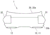
Fig. 1 is an exploded perspective view showing an appearance of a shoe 100 according to embodiment 1. The shoe 100 comprises a vamp 9 and a sole 1. The upper 9 is bonded or sewn to the peripheral edge of the sole 1 to cover the upper side of the foot. The sole 1 includes an outsole 10 (see fig. 3), a bottom portion 20, a deformation inhibitor 30, and the like, and is configured by stacking the deformation inhibitor 30 and the bottom portion 20 on the outsole 10, and further stacking an unillustrated insole and the like.
Fig. 2 is a schematic view of a model of the human foot superimposed on a plan view of the sole 1. The feet of the human body mainly comprise cuneiform bones Ba, cuboid bones Bb, navicular bones Bc, talus bones Bd, calcaneus Be, metatarsus Bf and phalanges Bg. The joints of the foot include the MP joint Ja, the tarsometatarsal joint Jb, and the tarsometatarsal joint Jc. The transverse tarsal joint Jc includes a calcaneal cuboid joint Jc1 formed by the cuboid bone Bb and the calcaneus Be, and a talonavicular joint Jc2 formed by the navicular bone Bc and the talus bone Bd.
In the present invention, the center line N of the foot is represented by a straight line connecting the center N3 of the greater thenar center N1 and the center N2 of the lesser thenar to the center N4 of the heel. For example, the front-rear direction Y is parallel to the center line N, and the width direction X is orthogonal to the center line N. A straight line along the width direction X (direction orthogonal to the center line N) passing through the heel-side end of the MP joint Ja is assumed as a line P. Further, a straight line along the width direction X, which is assumed to pass through the tip-side end of the transverse tarsal joint Jc of the wearer, is defined as a line Q. Here, the forefoot portion refers to a region on the toe side from the line P, the midfoot portion refers to a region from the line P to the line Q, and the hindfoot portion refers to a region on the heel side from the line Q. When the relationship between the line P and the line Q and the shoe 100 is observed, the line P is located in the range of 40% to 75% apart from the rear end on the heel side with respect to the entire length M of the shoe 100 in the direction of the center line N, for example. More preferably in the range of 55% to 70% from the rear end. The line Q is located in a range of 20% to 45% apart from the rear end on the heel side with respect to the entire length M of the shoe 100 in the direction of the center line N. More preferably in the range of 25% to 40% from the rear end.
Fig. 3 is an exploded perspective view of the shoe sole 1. The outsole 10 is formed over the entire length of the foot in the front-rear direction Y, at a bottom surface portion that contacts the road surface. In order to make the action from the foot landing to the foot pedaling smooth, the toe side is arranged at a position higher than the heel side. The outsole 10 is made of a material such as rubber, absorbs irregularities of a road surface, and has wear resistance and durability.
The outsole 10 includes an inner foot side covering portion 11 extending from the toe to the midfoot, an outer foot side covering portion 12 extending from the toe to the midfoot, and a heel covering portion 13. The inner sole covering 11 and the outer sole covering 12 of the outsole 10 are continuous with the toe and the midfoot, and extend from the midfoot to the hindfoot. The heel covering portion 13 is formed in a U shape extending from the rear end to the inner leg side and the outer leg side. The heel covering portion 13 may be continuous with the inner sole covering portion 11 and the outer sole covering portion 12, or may be separated with a certain gap as shown in fig. 3.
The bottom portion 20 is disposed on the outsole 10 and is formed over the entire length of the foot in the front-rear direction Y. In order to smooth the movement from the foot landing to the foot stepping, the toe side of the sole 20 is disposed higher than the heel side. The bottom portion 20 has recesses 21 at the inner leg side and outer leg side edges. The recess 21 is formed so as to pass through the lower surface side and the left and right side surfaces of the bottom portion 20, and extends from the front leg portion to the rear leg portion.
The deformation inhibiting portion 30 includes an inner leg side deformation inhibiting portion 31 and an outer leg side deformation inhibiting portion 32 formed in a rod shape. The inner leg side deformation inhibitor 31 and the outer leg side deformation inhibitor 32 extend from the front leg portion to the rear leg portion on the inner leg side and the outer leg side of the bottom portion 20, and are fitted into and bonded to the recess 21 provided at the edge portion of the bottom portion 20. The deformation inhibitor 30 is provided at a position offset to the lower portion of the bottom portion 20 in the vertical direction, and is provided between the outsole 10 and the bottom portion 20. The deformation inhibiting portion 30 has a higher hardness than the outsole 10 and the bottom portion 20, and further has a higher rigidity against bending deformation in the vertical direction than the outsole 10 and the bottom portion 20. The bending rigidity of the deformation inhibitor 30 is set to, for example, 20N/mm to 50N/mm. Here, the bending rigidity of the deformation inhibiting portion 30 is defined as a rigidity when the heel-side end portion of the deformation inhibiting portion 30 is fixed and the toe-side end portion is pressed down in the vertical direction.
Fig. 4 (base:Sub>A) isbase:Sub>A bottom view of the shoe sole 1, and fig. 4 (b) isbase:Sub>A cross-sectional view taken along linebase:Sub>A-base:Sub>A shown in fig. 4 (base:Sub>A). The inner leg side deformation inhibitor 31 and the outer leg side deformation inhibitor 32 have a rectangular cross section and are bonded to the left and right side surfaces of the bottom part 20 at the inner surface 31a and the inner surface 32 a. The lower end portions of the inner surface 31a and the inner surface 32a are covered by the inner leg covering portion 11 and the outer leg covering portion 12 of the outsole 10, and separation of the bottom portion 20 from the inner leg deformation inhibitor 31 and the outer leg deformation inhibitor 32 is inhibited. Further, the deformation inhibiting portions 30 may be formed outside the area where the wearer's foot contacts the sole 20.
Fig. 5 (base:Sub>A) and 5 (b) are cross-sectional views of the modified sole 1 taken along linebase:Sub>A-base:Sub>A shown in fig. 4 (base:Sub>A). The inner leg side deformation inhibiting portion 31 and the outer leg side deformation inhibiting portion 32 shown in fig. 5 (a) have a triangular cross section, and the inner side surface 31a and the inner side surface 32a are inclined so as to extend inward in the left-right direction (width direction X) as they face downward. The lower ends of the inner surface 31a and the inner surface 32a are covered by the inner leg covering portion 11 and the outer leg covering portion 12 of the outsole 10, and the separation of the bottom portion 20 from the inner leg deformation inhibiting portion 31 and the outer leg deformation inhibiting portion 32 is inhibited. Further, the inner leg side deformation inhibitor 31 and the outer leg side deformation inhibitor 32 are inclined so as to extend inward in the left-right direction as they face downward by the inner side surface 31a and the inner side surface 32a, thereby inhibiting a firm feeling at the portion where the foot contacts.
The inner leg side deformation inhibitor 31 and the outer leg side deformation inhibitor 32 shown in fig. 5 (b) are formed in an L-shape in cross section. The inner surface 31a and the inner surface 32a are formed in a stepped shape so as to have a step portion. The lower ends of the inner surface 31a and the inner surface 32a are covered by the inner leg covering portion 11 and the outer leg covering portion 12 of the outsole 10, and the separation of the bottom portion 20 from the inner leg deformation inhibiting portion 31 and the outer leg deformation inhibiting portion 32 is inhibited.
Fig. 6 (a) is a side view of the outer side of the sole 1, and fig. 6 (b) is a longitudinal sectional view of the sole shown in fig. 2 including the center line N. When the sole 1 is placed on a flat virtual surface S such as the ground, for example, the rear bottom surface 24 from the midfoot portion to the hindfoot portion is in contact with the virtual surface S. The rear bottom surface portion 24 may be entirely in contact with the imaginary plane S in the front-rear direction, or may be partially separated from the imaginary plane S, for example, as in the rear portion of the heel portion. In order to improve the stability from the heel to the midfoot portion when landing, the rear bottom surface portion 24 is preferably provided at least 20%, more preferably at least 35%, of the entire length M of the sole 1 at the portion in surface contact with the heel and the midfoot portion. Here, in the case where fine irregularities are provided on the rear bottom surface portion 24, the surface passing through the lowermost surface of these irregularities can be regarded as the imaginary rear bottom surface portion 24.
The front bottom surface portion 25 continuous with the front portion of the rear bottom surface portion 24 and extending toward the toe portion 26 is provided so as to be separated from the imaginary plane S. The front bottom surface portion 25 rises forward and reaches the toe portion 26. The front bottom surface portion 25 is formed only by a curved and linear surface, and does not have a portion that descends with the direction toward the front. The boundary line between the rear bottom surface portion 24 and the front bottom surface portion 25 is located between a position 50% away from the front end with respect to the entire length M of the sole 1 (equal to the entire length of the shoe 100, hereinafter, the same applies) and a point P0 corresponding to the MP joint. The rear bottom surface portion 24 and the front bottom surface portion 25 form a bottom surface portion 60. Further, the point P0 corresponding to the MP joint may be a position corresponding to the greater thenar in the upper surface of the bottom portion 20 as shown in fig. 6 (b), or may be a position corresponding to the lesser thenar in the MP joint. That is, P0 may be located in a range of 55 to 75% of the entire length M from the rear end of the sole 1.
The height L3 of the toe portion 26 is set to the height from the virtual plane of the point P3 where the edge portion 26a joined to the shoe upper 9 rises on the upper surface of the sole 20 (the surface on the medial side of the shoe 100) shown in fig. 6 (b). The height L3 of the toe portion 26 may be set to a height from the virtual plane of the point P4 at the forefront of the outer shape of the toe portion 26. In the following description, the height of the point P3 from the virtual plane is defined as the height L3 of the toe portion 26.
The thickness of the sole 1 on the rear bottom surface portion 24 side is based on either the thickness L1 of the sole 1 at the heel point P1 or the thickness L2 of the sole 1 at the midfoot point P2. The height L3 of the toe portion 26 is set to 100% to 250% of the thickness L1 of the sole 1 at the heel point P1. The height L3 of the toe portion 26 is preferably set to 170% or more of the thickness L1 of the sole 1 at the heel point P1. The height L3 of the toe portion 26 is set to 100% to 250% of the thickness L1 of the sole 1 at the point P2 of the midfoot portion. The height L3 of the toe portion 26 is preferably 170% or more of the thickness L1 of the sole 1 at the point P2 of the midfoot. The position of the mid-foot point P2 may be defined by the thickest portion of the positions around 30% to 40% of the entire length M from the rear end of the sole 1. When the height L3 of the toe portion 26 is set to a height from the point P4, it is 80% or more and 250% or less of the thickness L1 of the sole 1 at the point P2 of the midfoot portion, and preferably 150% or more of the thickness L1 of the sole 1 at the point P2 of the midfoot portion.
The position of the point P1 in the heel portion may be defined as the thickest portion in the heel portion (the range of 15% to 30% of the entire length M from the rear end of the sole 1), and the thickness dimension of the sole 1 at the point P1 is set to 20mm or more, for example. The bending rigidity in the extension direction of the sole 1 corresponding to the MP joint portion in the 3-point bending is, for example, 20N/mm or more. In the 3-point bending test, the MP joint portion was supported at both ends in the front-rear direction by 8cm, and the center between both ends was pressed downward to determine the relationship between displacement and load, thereby obtaining the slope of the displacement-load curve at a displacement of 5mm to 6 mm. In a non-loaded state in which the sole 1 is not loaded with a foot, the difference between the thickness of the sole 1 in the heel portion and the thickness of the sole 1 at a position corresponding to the MP joint portion is set to be, for example, within 5 mm.
Fig. 7 (a) and 7 (b) are schematic views for explaining the upper surface portion 61 of the shoe sole 1. Fig. 7 (a) and 7 (b) show cross-sectional views equivalent to fig. 6 (b). The first upper surface portion 27 is a surface formed from the rear leg portion to the middle leg portion and included in a specific parallel condition with respect to the virtual surface S in a no-load state. Here, the plane included in the specific parallel condition is a plane which is located in a region where the difference in height between SU1 and SU2 is 12mm or less between the virtual plane SU1 which is the highest plane and the virtual plane SU2 which is the lowest plane in a region including a position (rear portion) of 15% of the entire length M from the front end (front portion) of the first upper surface portion 27 and the rear end of the sole 1 described below, and which is parallel to the virtual plane S or has a downward slope from the rear portion toward the front portion. Fig. 7 (a) shows a case where the first upper surface portion 27 is parallel to the virtual surface S. Fig. 7 (b) shows the first upper surface portion 27 formed with a descending slope in which the amount of decrease in height of the front portion with respect to the rear portion is 5 mm. In order to avoid the foot bottom from having a feeling of strangeness, the first upper surface portion 27 may be formed in a flat shape with few irregularities, or may have some irregularities, height differences in the width direction, twists, or the like.
The second upper surface portion 28 is continuous with the front end of the first upper surface portion 27, and rises forward to reach the toe portion 26. The second upper surface portion 28 is formed only by a curved and linear surface that rises forward, and has no portion that falls forward, and is curved in a concave shape with respect to the upper side as shown in fig. 7 (a) and 7 (b). A boundary line (front end) between the first upper surface portion 27 and the second upper surface portion 28 is located at a distance of, for example, 25% to 45% from the front end with respect to the entire length M of the shoe sole 1.
In fig. 7 (a) and 7 (b), the upper surface of the bottom part 20 of the shoe sole 1 is described, and when an insole (not shown) is provided on the bottom part 20, the first upper surface part 27 and the second upper surface part 28 may be defined with respect to the upper surface of the insole.
The outsole 10 is made of, for example, rubber or rubber foam, thermoplastic Polyurethane (TPU), thermoplastic elastomer, or thermosetting elastomer. The bottom portion 20 is formed of, for example, a resin foam. As the resin, a polyolefin resin, an Ethylene Vinyl Acetate copolymer (EVA), a styrene-based elastomer, or the like is used, and any other component such as a fiber or the like may be appropriately contained. The deformation inhibiting portion 30 is formed of, for example, a polyolefin resin, or a resin foam such as EVA or styrene elastomer, and may contain any other component, for example, a fiber such as cellulose nanofiber, as appropriate.
For example, the hardness of the outsole 10 is HA70. For example, the hardness of the bottom portion 20 is HC55, and the hardness of the deformation inhibitor 30 is HC 67.
Next, the operation of the shoe 100 will be described. Fig. 8 is a diagram for explaining the rotation of the ankle joint in the forward and backward directions. The section a in fig. 8 shows a case where the bottom surface of the sole 1 is substantially flat and the ankle joint turns more forward and backward. In the section a, the angle α (α 2) of the ankle joint is reduced by the body weight moving forward and the ankle joint bending forward after landing. The movement of stretching the muscles of the foot is generated by the rotation of the ankle joint. Then, until the foot is stepped on, the angle α (α 3) of the ankle joint becomes larger.
On the other hand, a section B in fig. 8 shows a case where the sole 1 has the front sole portion 25 and the ankle joint turns less forward and backward. In section B, when the body moves forward after landing, the sole 1 rotates so that the front sole portion 25 contacts the road surface, and therefore the rotation toward the front side is suppressed, and the change in the angle α (α 2) of the ankle joint is small. Then, until the foot is stepped on, the change in the angle α (α 3) of the ankle joint is small.
Fig. 9 is an example of a graph showing energy consumption in the ankle joint. The horizontal axis of fig. 9 represents time, and the vertical axis represents energy consumption of the ankle joint, and energy consumption in each of the cases of the section a and the section B of fig. 8 is compared. For convenience, the muscle contraction is represented as a positive direction, and the stretching is represented as a negative direction.
The energy consumption at landing is greater in the case of the sole 1 of section a than in the case of the sole 1 of section B. The energy consumption at the time of landing is mainly reduced by the cushioning member 22 provided at the heel portion of the sole 1. As described in fig. 8, the rotation of the ankle joint α can be reduced in the case of the section B as compared with the case of the section a after the landing until the stepping, and accordingly, the energy consumption becomes small in the case of the section B.
The sole 1 of the shoe 100 is provided with the rear sole portion 24 to ensure stability when the foot lands on the ground. The toe portion 26 is located higher than the rear sole portion 24, and reduces the energy consumption by reducing the forward and backward rotation of the ankle joint during walking and running, thereby reducing the burden on the foot. Referring to fig. 6 (b), the height L3 of the toe portion 26 from the virtual plane S is set to 100% or more with respect to the thickness L1 of the rear bottom portion 24 at the rear heel portion, thereby exhibiting an effect of reducing the energy consumption. The height L3 of the toe portion 26 from the virtual plane S may be preferably set to 170% or more with respect to the thickness L1 of the rear bottom portion of the rear bottom surface portion 24. The height L3 of the toe portion 26 from the virtual plane S is set to 250% or less with respect to the thickness L1 at the heel portion, thereby limiting the bending angle of the MP joint portion of the foot to a certain range.
By defining the height L3 of the toe portion 26 from the virtual plane S based on the thickness L1 of the heel portion, the burden on the ankle joint is reduced when the sole 1 is turned toward the toe portion after the heel portion lands. The height L3 of the toe portion 26 from the virtual plane S may be defined to be 100% or more and 250% or less with respect to the thickness L2 of the center leg portion. In this case, it is considered that the sole 1 reduces the burden on the ankle joint at least when the midfoot portion is grounded and turned toward the toe portion 26. The height L3 of the toe portion 26 from the virtual plane S is preferably set to 100% or more with respect to the thickness L2 of the midfoot portion.
Referring to fig. 7 (a) and 7 (b), as described above, the first upper surface portion 27 is formed as a surface included in a specific parallel condition. The second upper surface portion 28 is formed so as to be continuous with the front end of the first upper surface portion 27 and to rise forward, and the upward slope in the second upper surface portion 28 toward the front is gentle by setting the downward slope in the first upper surface portion 27 toward the front within a certain range. The upward slope toward the front in the second upper surface portion 28 becomes gentle, and the bending angle toward the upper side at the MP joint portion of the foot can be suppressed.
The rear bottom surface portion 24 has a portion in surface contact with the imaginary plane S at the rear leg portion and the middle leg portion, and thus stability at the time of landing on the ground at the rear bottom surface portion 24 can be increased. Further, the front bottom surface portion 25 and the front portion of the rear bottom surface portion 24 extend continuously and curvedly to the toe portion 26, and the turning of the foot can be made smooth. Further, by making the radius of curvature R1 at the rear portion where the front bottom surface portion 25 and the rear bottom surface portion are continuous smaller than the radius of curvature R2 of the toe portion, the sole 1 can be easily functioned after landing in the midfoot portion. The position where the radius of curvature R1 smaller than the radius of curvature R2 is present is provided along the MP joint portion from the medial side to the lateral side, for example. When R1 is 85% or less of R2, the effect of making the rotation smoother can be obtained.
The front bottom surface portion 25 includes a point P0 facing the MP joint portion of the foot in the region, and the motion of the MP joint portion of the foot is reduced in the process of the sole 1 rotating after the midfoot portion lands on the ground until the toe portion 26 lands on the ground. The motion of the MP joint part of the foot is reduced, so that the energy consumption of the MP joint part is reduced, and the load of expansion and contraction of the MP joint part is reduced.
The deformation inhibitor 30 has a higher hardness than the bottom part 20, and functions to inhibit the deformation of the sole 1 and the foot, and easily maintains the shape of the foot constant. The deformation inhibiting portions 30 include an inner leg side deformation inhibiting portion 31 and an outer leg side deformation inhibiting portion 32, thereby allowing the shoe 1 to be twisted about an axis in the front-rear direction. For example, when the ground on which the ground lands has undulations on the inner leg side and the outer leg side due to inclination or the like, the inner leg side deformation inhibiting portion 31 and the outer leg side deformation inhibiting portion 32 are deformed independently of each other, and the entire shoe 1 can be twisted around the axis in the front-rear direction and follow the undulations of the ground.
The bottom portion 20 has a lower hardness than the deformation suppressing portion 30, and functions as a deformation allowing portion for relaxing impact at the time of landing or unevenness of a road surface in the shoe sole 1. The bottom portion 20 is provided above the deformation inhibiting portion 30, and is in contact with the foot of the wearer, and is low in hardness, so that it is possible to further alleviate the projection due to the load caused by the impact on the foot or the like, or the unevenness of the road surface. Further, the deformation inhibitor 30 is formed outside the area of the bottom part 20 that the wearer's foot contacts, and thus can inhibit the inner and outer foot sides of the foot from becoming hard to the touch.
Generally, the bending rigidity when a plate-like material is bent is determined by the young's modulus and the second moment of area of the material. If the material properties are the same (for example, the hardness and the like are the same) and the width is also the same, the bending rigidity is proportional to the thickness of the material to the third power. Therefore, when the thickness of the shoe sole 1 is reduced, it is necessary to compensate for the material properties by inserting a high-strength member such as fiber reinforced plastic or the like or increasing the hardness of the outsole 10. The outsole 10 also functions as a deformation inhibitor.
The toe portion 26 of the sole 1 rises to a height of 150% or more of the thickness dimension L1 of the sole 1 at the heel portion or the thickness dimension L2 of the sole 1 at the midfoot portion (for example, a portion 30% from the rear end of the entire length M), and when the bending rigidity in the longitudinal direction of the forefoot portion of the sole 1 (the rigidity at the position corresponding to the MP joint portion) is approximately 3 times or more of that of a normal running shoe (reference value: 3N/mm), the deformation of the sole 1 is suppressed, and an effect of reducing the burden on the ankle joint is exhibited.
When the rising height of the toe part 26 is low, the sole 1 is hard and is not effective. Since the change in the angle of the foot joint during the foot contact with the ground can be reduced during walking or running, and the angular velocity can be reduced, the workload on the ankle joint can be reduced, and walking or running can be performed with less effort.
(embodiment mode 2)
Fig. 10 (a) to 10 (c) are bottom views of the shoe sole 1 according to embodiment 2, with the outsole omitted. In the shoe sole 1 shown in fig. 10 (a), the length of the deformation inhibiting portion 30 in the front-rear direction of the inner leg side deformation inhibiting portion 31 is longer than the length of the outer leg side deformation inhibiting portion 32. The inner leg deformation inhibitor 31 extends from the front leg to the vicinity of the center of the rear leg in the front-rear direction, and the outer leg deformation inhibitor 32 extends from the front leg to the rear end of the center leg or the front end of the rear leg. This alleviates the suppression of the bending deformation of the sole 1 in the vertical direction on the lateral side.
In the sole 1 shown in fig. 10 (b), the length of the deformation suppressing parts 31 and 32 on the inner foot side in the front-rear direction of the deformation suppressing part 30 is the same, and extends from the front foot part to the rear end of the midfoot part or the front end of the hindfoot part. This alleviates the suppression of the bending deformation of the sole 1 in the vertical direction on the inner leg side and the outer leg side.
In the sole 1 shown in fig. 10 (c), the lengths of the inner leg deformation inhibitor 31 and the outer leg deformation inhibitor 32 of the deformation inhibitor 30 in the front-rear direction are the same, and extend from the front leg to the vicinity of the center of the rear leg in the front-rear direction. The deformation suppressing portions 30 include a connecting portion 33 that connects the vicinity of the center of the inner leg side deformation suppressing portion 31 in the front-rear direction and the vicinity of the rear end of the outer leg side deformation suppressing portion 32. The deformation inhibiting portion 30 includes the connecting portion 33, and thus can maintain the positional relationship between the inner leg side and the outer leg side, thereby improving durability.
(embodiment mode 3)
Fig. 11 is a perspective view showing an appearance of a shoe sole 1 according to embodiment 3, and fig. 12 is an exploded perspective view of the shoe sole 1. Fig. 13 is a sectional view of the shoe sole 1 at a section equivalent to fig. 4 (b). The sole 1 according to embodiment 3 includes the outsole 10, the bottom portion 20, and the deformation inhibitor 30, as in embodiments 1 and 2, but the bottom portion 20 is divided into an upper bottom portion 20a and a lower bottom portion 20b. The deformation inhibiting portions 30 include, on the toe side, connecting portions 34 that connect the inner leg side deformation inhibiting portions 31 and the outer leg side deformation inhibiting portions 32.
The bottom portion 20 has recesses 21 formed on the inner leg side, outer leg side and toe portion of the lower bottom portion 20b, and the deformation inhibiting portions 30 are fitted into the recesses 21. The deformation inhibiting portions 30 are sandwiched and bonded between the upper and lower bottoms 20a and 20b. Also, the lower surface of the upper sole 20a is bonded to the upper surface of the lower sole 20b. Further, the upper bottom portion 20a and the lower bottom portion 20b can be formed by integral molding, and in the case where the shape of the recess 21 into which the deformation suppressing member 30 is fitted is complicated, the manufacturability of separating the upper bottom portion 20a from the lower bottom portion 20b is good as shown in fig. 12.
In addition, the deformation inhibiting portions 30 connect the inner leg side deformation inhibiting portions 31 and the outer leg side deformation inhibiting portions 32 at the toe side by the connecting portions 34, so that handling at the time of assembling the shoe sole 1 is facilitated, and assembling property is good.
As shown in fig. 13, the deformation inhibiting portion 30 is located at an upper portion in the vertical direction of the lower bottom portion 20b, and the lower surface side is covered by the lower bottom portion 20b. This prevents the deformation inhibitor 30 from being exposed to the lower surface side of the shoe sole 1, and prevents the bonded portion of the deformation inhibitor 30 from peeling off. The deformation inhibiting portion 30 is disposed in the vicinity of the center of the bottom portion 20 including the upper bottom portion 20a and the lower bottom portion 20b as viewed in the vertical direction, and is disposed in a positional relationship biased toward the upper portion of the bottom portion 20 in the vertical direction by reducing the thickness of the upper bottom portion 20 a.
The sole 1 is formed such that the toe side is positioned above the heel side as in embodiment 1, and when the wearer of the shoe 100 walks or runs, energy consumption at the ankle joint is suppressed, and walking or running can be performed with little effort.
Next, the features of the shoe sole 1 and the shoe 100 according to the embodiment and the modification will be described.
The shoe sole 1 includes a bottom portion 20 and a deformation inhibiting portion 30. The sole portion 20 includes a rear sole portion 24 and a toe portion 26, the rear sole portion 24 is formed from the rear sole portion to the middle sole portion and contacts the virtual surface S when placed on the flat virtual surface S, and the toe portion 26 has a height from the virtual surface S of 100% to 250% with respect to a thickness dimension of the rear sole portion 24. The deformation inhibiting portion 30 is disposed at the edge portions of the sole portion 20 on the inner leg side and the outer leg side, extends from the front leg portion to the middle leg portion following the sole portion 20, and has a higher hardness than the sole portion 20. This ensures the stability of the sole 1 for the rear bottom surface portion 24 to land on the ground, and reduces the burden on the ankle joint during walking and running in the forward direction.
The shoe sole 1 includes a bottom portion 20 and a deformation inhibiting portion 30. The bottom portion 20 includes a rear bottom portion 24 and a front bottom portion 25, the rear bottom portion 24 is formed from the rear leg portion to the middle leg portion, and contacts the virtual surface S when placed on the flat virtual surface S, and the front bottom portion 25 is curved to extend to a toe portion 26 continuously formed in the front portion of the rear bottom portion 24, and is separated from the virtual surface S. The deformation inhibitor 30 is disposed at the edge of the sole 20 on the inner leg side and the outer leg side, extends from the front leg to the center leg following the sole 20, and has higher rigidity than the sole 20. The rigidity of the deformation suppressing portion 30 against bending deformation in the vertical direction is 20N/mm to 50N/mm. This ensures the stability of the sole 1 for the rear bottom surface portion 24 to land on the ground, and reduces the burden on the ankle joint during walking and running in the forward direction. The bending rigidity of the deformation inhibitor 30 is preferably 1.5 times or more and 4 times or less the bending rigidity of the other portion, for example, the central portion of the shoe sole 20 sandwiched between the inner leg side deformation inhibitor 31 and the outer leg side deformation inhibitor 32. If the bending rigidity of the deformation inhibitor 30 is low, the sole 1 is easily deformed. If the bending rigidity of the deformation inhibitor 30 is too high, a large shearing force may be applied to the boundary region with another portion, and the shape or the like needs to be modified.
The shoe sole 1 includes a bottom portion 20 and a deformation inhibiting portion 30. The bottom part 20 includes a bottom part 60, the bottom part 60 includes a rear bottom part 24 and a front bottom part 25, the rear bottom part 24 is formed from a rear leg to a middle leg and contacts with a flat virtual surface S when placed on the virtual surface S, and the front bottom part 25 is curved to extend to a toe part 26 continuously formed in a front part of the rear bottom part 24 and is separated from the virtual surface S. The deformation inhibitor 30 is disposed at the edge of the sole 20 on the inner leg side and the outer leg side, extends from the front leg to the middle leg following the sole 20, and has a higher hardness than the sole 20. The bottom portion 20 includes an upper surface portion 61, the upper surface portion 61 including a first upper surface portion 27 and a second upper surface portion 28, the first upper surface portion 27 being formed from the rear leg portion to the middle leg portion and being formed by a surface parallel to the virtual surface S in a no-load state or descending from the rear portion toward the front, the second upper surface portion 28 being formed by a surface continuous to the front end of the first upper surface portion 27 and ascending toward the front, and reaching the toe portion 26. The region facing the MP joint portion of the foot is disposed on the front bottom surface portion 25 in the bottom surface portion 60, and is disposed on the second upper surface portion 28 in the upper surface portion 61. In this way, in the shoe sole 1, the downward slope toward the front in the first upper surface portion 27 is set within a certain range, and the upward slope toward the front in the second upper surface portion 28 becomes gentle, so that the toe of the foot can be suppressed from being excessively bent upward.
The deformation inhibiting portion 30 is formed outside the area of the bottom portion 20 with which the foot is in contact. This can suppress the stiffness of the inner and outer foot sides of the foot in the sole 1.
The deformation inhibitor 30 connects the inner leg side and the outer leg side on the toe side. This facilitates handling of the shoe sole 1 during assembly, and improves assembly performance.
Further, the deformation inhibiting portion 30 extends toward the rear foot portion longer on the inner foot side than on the outer foot side. This suppresses deformation of the sole 1 on the inner foot side, and suppresses bending deformation of the outer foot side in the vertical direction.
The deformation inhibiting portion 30 is disposed to be upwardly biased in the vertical direction of the bottom portion 20. The bottom portion 20 is formed so as to cover the lower surface side of the deformation inhibiting portion 30. This prevents the portion of the sole 1 bonded to the bottom portion 20 at the deformation inhibiting portion 30 from being exposed to the lower surface side, thereby improving durability.
The deformation inhibitor 30 is disposed offset downward in the vertical direction of the bottom portion 20, and the outsole 10 is formed so as to cover the deformation inhibitor 30 and the lower surface side of the bottom portion 20. Thus, the sole 1 can protect the bonded portion of the deformation inhibitor 30 and the bottom portion 20 by the outsole 10, and can improve durability.
Further, the inner side surfaces of the deformation inhibiting portions 30 that intersect the lateral direction of the foot are inclined so as to extend inward in the lateral direction as they face downward. This can prevent the sole 1 from becoming hard to the touch of the portion with which the foot is in contact.
At least one of the bottom portion 20 and the deformation inhibiting portion 30 is formed of a foam material. This enables the sole 1 to reduce the weight of the constituent members.
The shoe 100 includes any one of the above-described shoe soles 1 and a shoe upper 9 disposed on the shoe sole 1. This ensures the stability of the rear sole portion 24 at the ground contact, and reduces the burden on the ankle joint when walking or running forward.
The above description has been based on the embodiments of the present invention. It will be understood by those skilled in the art that these embodiments are illustrative, and various changes and modifications can be made within the scope of the claims of the present invention, and such changes and modifications are also within the scope of the claims of the present invention. Accordingly, the description and drawings in this specification are to be regarded in an illustrative rather than a restrictive sense.
Industrial applicability of the invention
The invention relates to a sole and a shoe.
Description of the symbols
1: shoe sole
20: bottom part
30: deformation inhibiting part
24: rear bottom surface part
25: front bottom surface
26: toe part
27: a first upper surface part
28: a second upper surface part
60: bottom surface part
61: upper surface part
9: shoe upper
100: shoes with removable cover
Claims (11)
1. A shoe sole, characterized by comprising:
a bottom portion including a rear bottom surface portion and a toe portion, the rear bottom surface portion being formed from a rear foot portion to a middle foot portion, and being in contact with a flat virtual surface when placed on the virtual surface, the toe portion having a height from the virtual surface of 100% to 250% with respect to a thickness dimension of the rear bottom surface portion; and
and a deformation inhibiting portion which is arranged at the edge portions of the bottom portion on the inner leg side and the outer leg side, extends from the front leg portion to the center leg portion following the bottom portion, and has a higher hardness than the bottom portion.
2. A shoe sole, comprising:
a bottom portion including a rear bottom surface portion and a front bottom surface portion, the rear bottom surface portion being formed from a rear leg portion to a middle leg portion, contacting a flat imaginary surface when placed thereon, the front bottom surface portion being curved to extend to a toe portion continuously formed at a front portion of the rear bottom surface portion, and being separated from the imaginary surface; and
a deformation inhibiting portion which is arranged at the edge portions of the bottom portion on the inner leg side and the outer leg side, extends from the front leg portion to the center leg portion following the bottom portion, and has higher rigidity than the bottom portion,
the sole is characterized in that:
the rigidity of the deformation inhibiting portion against bending deformation in the vertical direction is 20N/mm to 50N/mm.
3. A shoe sole, comprising:
a bottom portion including a bottom surface portion including a rear bottom surface portion and a front bottom surface portion, the rear bottom surface portion being formed from a rear leg portion to a middle leg portion, contacting a flat imaginary surface when placed on the imaginary surface, the front bottom surface portion being curved to extend to a toe portion continuously formed at a front portion of the rear bottom surface portion, and being separated from the imaginary surface; and
a deformation inhibiting portion which is arranged at the edge portions of the bottom portion on the inner leg side and the outer leg side, extends from the front leg portion to the center leg portion following the bottom portion, and has a higher hardness than the bottom portion,
the sole is characterized in that:
the bottom portion includes an upper surface portion including a first upper surface portion formed from a rear leg portion to a middle leg portion and formed of a surface parallel to the virtual surface in a no-load state or descending from a rear portion toward a front portion, and a second upper surface portion formed of a surface continuous with a front end of the first upper surface portion and ascending toward the front portion and reaching the toe portion,
an area facing a metatarsophalangeal joint of the foot is disposed on a front sole portion of the sole portions and on the second upper surface portion of the upper surface portions.
4. The sole according to any one of claims 1 to 3, wherein: the deformation inhibiting portion is formed outside an area in the bottom portion which the foot contacts.
5. The sole according to any one of claims 1 to 4, wherein: the deformation inhibiting portion connects the inner leg side and the outer leg side on the toe side.
6. The sole according to any one of claims 1 to 5, wherein: the deformation inhibiting portion extends toward the rear foot portion longer on the inner foot side than on the outer foot side.
7. The sole according to any one of claims 1 to 6, wherein: the deformation suppressing portion is disposed so as to be offset upward in the vertical direction of the bottom portion,
the bottom portion is formed so as to cover a lower surface side of the deformation inhibiting portion.
8. The sole according to any one of claims 1 to 6, wherein: the deformation suppressing portion is disposed so as to be biased downward in the vertical direction of the bottom portion,
an outsole is formed so as to cover the lower surface sides of the deformation inhibiting portion and the bottom portion.
9. The sole according to any one of claims 1 to 8, wherein: the deformation inhibiting portion is inclined such that an inner side surface intersecting with a left-right direction of the foot extends inward in the left-right direction as it goes downward.
10. The sole according to any one of claims 1 to 9, wherein: at least one of the bottom portion and the deformation inhibiting portion is formed of a foamed material.
11. A shoe, characterized by comprising:
the sole of any one of claims 1 to 10; and
and the vamp is arranged on the sole.
Applications Claiming Priority (1)
| Application Number | Priority Date | Filing Date | Title |
|---|---|---|---|
| PCT/JP2020/025211 WO2021260920A1 (en) | 2020-06-26 | 2020-06-26 | Shoe sole and shoe |
Publications (1)
| Publication Number | Publication Date |
|---|---|
| CN115666308A true CN115666308A (en) | 2023-01-31 |
Family
ID=79282186
Family Applications (1)
| Application Number | Title | Priority Date | Filing Date |
|---|---|---|---|
| CN202080101432.5A Pending CN115666308A (en) | 2020-06-26 | 2020-06-26 | Sole and shoe |
Country Status (5)
| Country | Link |
|---|---|
| US (1) | US20230240408A1 (en) |
| EP (1) | EP4154749A4 (en) |
| JP (1) | JPWO2021260920A1 (en) |
| CN (1) | CN115666308A (en) |
| WO (1) | WO2021260920A1 (en) |
Family Cites Families (10)
| Publication number | Priority date | Publication date | Assignee | Title |
|---|---|---|---|---|
| JPS4925651U (en) * | 1972-06-09 | 1974-03-05 | ||
| JPS6041122Y2 (en) * | 1982-12-10 | 1985-12-13 | 月星化成株式会社 | footwear soles |
| JP3041007U (en) * | 1997-02-28 | 1997-09-05 | 京阪通商株式会社 | Shoe soles and shoes and sandals containing them |
| JP2007143938A (en) * | 2005-11-29 | 2007-06-14 | Strong Co Ltd | Slipper |
| FR2898252B1 (en) * | 2006-03-07 | 2008-07-04 | Salomon Sa | SHOE AND ITS SEMELAGE |
| CH704561A8 (en) * | 2011-02-18 | 2012-10-15 | Joya Schuhe AG | Shoe. |
| KR20150132428A (en) * | 2013-03-15 | 2015-11-25 | 백조이 오쏘틱스 엘엘씨 | Neutral posture orienting footbed system for footwear |
| US20180084864A1 (en) * | 2015-03-23 | 2018-03-29 | Asics Corporation | Shoe having stabilizer |
| WO2017058420A1 (en) * | 2015-10-02 | 2017-04-06 | Nike Innovate C.V. | Plate for footwear |
| FR3074651B1 (en) * | 2017-12-13 | 2021-05-21 | Jet Green | SPORTS SHOE EQUIPPED WITH A SHELL INTERPOSED BETWEEN THE UPPER AND A COMFORT SOLE |
-
2020
- 2020-06-26 CN CN202080101432.5A patent/CN115666308A/en active Pending
- 2020-06-26 US US18/002,637 patent/US20230240408A1/en active Pending
- 2020-06-26 EP EP20942270.8A patent/EP4154749A4/en active Pending
- 2020-06-26 JP JP2022532207A patent/JPWO2021260920A1/ja active Pending
- 2020-06-26 WO PCT/JP2020/025211 patent/WO2021260920A1/en unknown
Also Published As
| Publication number | Publication date |
|---|---|
| WO2021260920A1 (en) | 2021-12-30 |
| EP4154749A1 (en) | 2023-03-29 |
| JPWO2021260920A1 (en) | 2021-12-30 |
| EP4154749A4 (en) | 2023-07-12 |
| US20230240408A1 (en) | 2023-08-03 |
Similar Documents
| Publication | Publication Date | Title |
|---|---|---|
| US11937665B2 (en) | Footwear including a stabilizing sole | |
| JP6963369B2 (en) | Sole structure for shoes and shoes using it | |
| US7263788B2 (en) | Sole-mounted footwear stability system | |
| US20180199666A1 (en) | Shoe having shoe sole with divided forefoot portion | |
| US20190000180A1 (en) | Shoe having shoe sole with divided rear foot portion | |
| US11825903B2 (en) | Shoe sole and shoe | |
| EP3275330B1 (en) | Shoe having stabilizer | |
| US20150157089A1 (en) | Shoe sole for gait correction or gait preservation | |
| CN113545561B (en) | Shoes with air-permeable layer | |
| CN112292054B (en) | Shoes with removable sole | |
| CN115666308A (en) | Sole and shoe | |
| CN113260272B (en) | Shoes with removable sole | |
| JP2022156974A (en) | Sole structure and show using the same | |
| JP7225296B2 (en) | Sole structure and shoes using the same | |
| JP3241919U (en) | insoles and footwear | |
| JPWO2021260920A5 (en) | ||
| JP7466241B1 (en) | Insoles and footwear | |
| JP7326378B2 (en) | shoe structure | |
| JP7350346B2 (en) | footwear | |
| US20240000184A1 (en) | Sole structure and shoe with a plurality of concave and convex shapes | |
| JP6997543B2 (en) | Shoe correction parts and shoes |
Legal Events
| Date | Code | Title | Description |
|---|---|---|---|
| PB01 | Publication | ||
| PB01 | Publication | ||
| SE01 | Entry into force of request for substantive examination | ||
| SE01 | Entry into force of request for substantive examination |