EP3801105B1 - Footwear sole plate with forefoot through hole - Google Patents
Footwear sole plate with forefoot through hole Download PDFInfo
- Publication number
- EP3801105B1 EP3801105B1 EP19722434.8A EP19722434A EP3801105B1 EP 3801105 B1 EP3801105 B1 EP 3801105B1 EP 19722434 A EP19722434 A EP 19722434A EP 3801105 B1 EP3801105 B1 EP 3801105B1
- Authority
- EP
- European Patent Office
- Prior art keywords
- sole plate
- ridges
- facing surface
- sole
- crests
- Prior art date
- Legal status (The legal status is an assumption and is not a legal conclusion. Google has not performed a legal analysis and makes no representation as to the accuracy of the status listed.)
- Active
Links
- 210000004744 fore-foot Anatomy 0.000 title claims description 58
- 239000006260 foam Substances 0.000 claims description 90
- 210000000452 mid-foot Anatomy 0.000 claims description 34
- 210000001872 metatarsal bone Anatomy 0.000 claims description 11
- 239000002131 composite material Substances 0.000 claims description 10
- 230000001788 irregular Effects 0.000 claims description 6
- 229920000049 Carbon (fiber) Polymers 0.000 claims description 5
- 239000004677 Nylon Substances 0.000 claims description 5
- 229910000831 Steel Inorganic materials 0.000 claims description 5
- 239000004917 carbon fiber Substances 0.000 claims description 5
- 230000007423 decrease Effects 0.000 claims description 5
- 239000000835 fiber Substances 0.000 claims description 5
- 210000001255 hallux Anatomy 0.000 claims description 5
- VNWKTOKETHGBQD-UHFFFAOYSA-N methane Chemical compound C VNWKTOKETHGBQD-UHFFFAOYSA-N 0.000 claims description 5
- 229920001778 nylon Polymers 0.000 claims description 5
- 239000010959 steel Substances 0.000 claims description 5
- 229920002725 thermoplastic elastomer Polymers 0.000 claims description 5
- 239000002023 wood Substances 0.000 claims description 5
- 239000012858 resilient material Substances 0.000 claims description 3
- 210000002683 foot Anatomy 0.000 description 27
- 210000000474 heel Anatomy 0.000 description 20
- 238000010521 absorption reaction Methods 0.000 description 10
- 238000005452 bending Methods 0.000 description 9
- 210000003414 extremity Anatomy 0.000 description 8
- 230000000875 corresponding effect Effects 0.000 description 7
- 239000000463 material Substances 0.000 description 6
- 230000000284 resting effect Effects 0.000 description 3
- 230000006835 compression Effects 0.000 description 2
- 238000007906 compression Methods 0.000 description 2
- 230000002045 lasting effect Effects 0.000 description 2
- 238000000034 method Methods 0.000 description 2
- 230000007935 neutral effect Effects 0.000 description 2
- 230000002093 peripheral effect Effects 0.000 description 2
- 230000000750 progressive effect Effects 0.000 description 2
- 210000000988 bone and bone Anatomy 0.000 description 1
- 210000000459 calcaneus Anatomy 0.000 description 1
- 230000002596 correlated effect Effects 0.000 description 1
- 230000003247 decreasing effect Effects 0.000 description 1
- 230000001419 dependent effect Effects 0.000 description 1
- 230000005489 elastic deformation Effects 0.000 description 1
- 238000009434 installation Methods 0.000 description 1
- 239000000203 mixture Substances 0.000 description 1
- 239000003607 modifier Substances 0.000 description 1
- 230000002787 reinforcement Effects 0.000 description 1
- 238000005096 rolling process Methods 0.000 description 1
- 210000003371 toe Anatomy 0.000 description 1
Images


Classifications
-
- A—HUMAN NECESSITIES
- A43—FOOTWEAR
- A43B—CHARACTERISTIC FEATURES OF FOOTWEAR; PARTS OF FOOTWEAR
- A43B13/00—Soles; Sole-and-heel integral units
- A43B13/02—Soles; Sole-and-heel integral units characterised by the material
- A43B13/12—Soles with several layers of different materials
-
- A—HUMAN NECESSITIES
- A43—FOOTWEAR
- A43B—CHARACTERISTIC FEATURES OF FOOTWEAR; PARTS OF FOOTWEAR
- A43B13/00—Soles; Sole-and-heel integral units
- A43B13/14—Soles; Sole-and-heel integral units characterised by the constructive form
- A43B13/143—Soles; Sole-and-heel integral units characterised by the constructive form provided with wedged, concave or convex end portions, e.g. for improving roll-off of the foot
- A43B13/146—Concave end portions, e.g. with a cavity or cut-out portion
-
- A—HUMAN NECESSITIES
- A43—FOOTWEAR
- A43B—CHARACTERISTIC FEATURES OF FOOTWEAR; PARTS OF FOOTWEAR
- A43B13/00—Soles; Sole-and-heel integral units
- A43B13/02—Soles; Sole-and-heel integral units characterised by the material
- A43B13/023—Soles with several layers of the same material
-
- A—HUMAN NECESSITIES
- A43—FOOTWEAR
- A43B—CHARACTERISTIC FEATURES OF FOOTWEAR; PARTS OF FOOTWEAR
- A43B13/00—Soles; Sole-and-heel integral units
- A43B13/02—Soles; Sole-and-heel integral units characterised by the material
- A43B13/026—Composites, e.g. carbon fibre or aramid fibre; the sole, one or more sole layers or sole part being made of a composite
-
- A—HUMAN NECESSITIES
- A43—FOOTWEAR
- A43B—CHARACTERISTIC FEATURES OF FOOTWEAR; PARTS OF FOOTWEAR
- A43B13/00—Soles; Sole-and-heel integral units
- A43B13/02—Soles; Sole-and-heel integral units characterised by the material
- A43B13/08—Wood
-
- A—HUMAN NECESSITIES
- A43—FOOTWEAR
- A43B—CHARACTERISTIC FEATURES OF FOOTWEAR; PARTS OF FOOTWEAR
- A43B13/00—Soles; Sole-and-heel integral units
- A43B13/02—Soles; Sole-and-heel integral units characterised by the material
- A43B13/12—Soles with several layers of different materials
- A43B13/125—Soles with several layers of different materials characterised by the midsole or middle layer
-
- A—HUMAN NECESSITIES
- A43—FOOTWEAR
- A43B—CHARACTERISTIC FEATURES OF FOOTWEAR; PARTS OF FOOTWEAR
- A43B13/00—Soles; Sole-and-heel integral units
- A43B13/14—Soles; Sole-and-heel integral units characterised by the constructive form
-
- A—HUMAN NECESSITIES
- A43—FOOTWEAR
- A43B—CHARACTERISTIC FEATURES OF FOOTWEAR; PARTS OF FOOTWEAR
- A43B13/00—Soles; Sole-and-heel integral units
- A43B13/14—Soles; Sole-and-heel integral units characterised by the constructive form
- A43B13/16—Pieced soles
-
- A—HUMAN NECESSITIES
- A43—FOOTWEAR
- A43B—CHARACTERISTIC FEATURES OF FOOTWEAR; PARTS OF FOOTWEAR
- A43B13/00—Soles; Sole-and-heel integral units
- A43B13/14—Soles; Sole-and-heel integral units characterised by the constructive form
- A43B13/18—Resilient soles
- A43B13/181—Resiliency achieved by the structure of the sole
- A43B13/185—Elasticated plates sandwiched between two interlocking components, e.g. thrustors
-
- A—HUMAN NECESSITIES
- A43—FOOTWEAR
- A43B—CHARACTERISTIC FEATURES OF FOOTWEAR; PARTS OF FOOTWEAR
- A43B13/00—Soles; Sole-and-heel integral units
- A43B13/14—Soles; Sole-and-heel integral units characterised by the constructive form
- A43B13/18—Resilient soles
- A43B13/181—Resiliency achieved by the structure of the sole
- A43B13/186—Differential cushioning region, e.g. cushioning located under the ball of the foot
-
- A—HUMAN NECESSITIES
- A43—FOOTWEAR
- A43B—CHARACTERISTIC FEATURES OF FOOTWEAR; PARTS OF FOOTWEAR
- A43B13/00—Soles; Sole-and-heel integral units
- A43B13/14—Soles; Sole-and-heel integral units characterised by the constructive form
- A43B13/18—Resilient soles
- A43B13/187—Resiliency achieved by the features of the material, e.g. foam, non liquid materials
- A43B13/188—Differential cushioning regions
-
- A—HUMAN NECESSITIES
- A43—FOOTWEAR
- A43B—CHARACTERISTIC FEATURES OF FOOTWEAR; PARTS OF FOOTWEAR
- A43B3/00—Footwear characterised by the shape or the use
- A43B3/0036—Footwear characterised by the shape or the use characterised by a special shape or design
-
- A—HUMAN NECESSITIES
- A43—FOOTWEAR
- A43B—CHARACTERISTIC FEATURES OF FOOTWEAR; PARTS OF FOOTWEAR
- A43B7/00—Footwear with health or hygienic arrangements
- A43B7/14—Footwear with health or hygienic arrangements with foot-supporting parts
- A43B7/1405—Footwear with health or hygienic arrangements with foot-supporting parts with pads or holes on one or more locations, or having an anatomical or curved form
- A43B7/1415—Footwear with health or hygienic arrangements with foot-supporting parts with pads or holes on one or more locations, or having an anatomical or curved form characterised by the location under the foot
- A43B7/1425—Footwear with health or hygienic arrangements with foot-supporting parts with pads or holes on one or more locations, or having an anatomical or curved form characterised by the location under the foot situated under the ball of the foot, i.e. the joint between the first metatarsal and first phalange
-
- A—HUMAN NECESSITIES
- A43—FOOTWEAR
- A43B—CHARACTERISTIC FEATURES OF FOOTWEAR; PARTS OF FOOTWEAR
- A43B7/00—Footwear with health or hygienic arrangements
- A43B7/14—Footwear with health or hygienic arrangements with foot-supporting parts
- A43B7/1405—Footwear with health or hygienic arrangements with foot-supporting parts with pads or holes on one or more locations, or having an anatomical or curved form
- A43B7/1415—Footwear with health or hygienic arrangements with foot-supporting parts with pads or holes on one or more locations, or having an anatomical or curved form characterised by the location under the foot
- A43B7/1445—Footwear with health or hygienic arrangements with foot-supporting parts with pads or holes on one or more locations, or having an anatomical or curved form characterised by the location under the foot situated under the midfoot, i.e. the second, third or fourth metatarsal
Definitions
- the present teachings generally include a sole plate for an article of footwear and a midsole system for an article of footwear.
- Footwear typically includes a sole structure configured to be located under a wearer's foot to space the foot away from the ground.
- Sole structures may typically be configured to provide one or more of cushioning, motion control, and resiliency.
- US 2011/0271553 A1 describes a footwear including an upper and a sole assembly coupled to the upper, with the sole assembly including an outsole with a ground-contacting surface and a midsole positioned above the outsole.
- the midsole includes a peripheral lasting member that defines a central aperture, and a cushioning member positioned at least above the peripheral lasting member.
- DE 19641866 A1 describes a footwear including an upper and a sole assembly coupled to the upper, with the sole assembly including an outsole and a midsole, wherein the midsole comprises a corrugated structure, i.e. the upper surface presents ridges while the opposite face presents groves aligned with the aforementioned ridges.
- a sole structure for an article of footwear comprises a midsole system according to claim 1. Particular embodiments are disclosed in dependent claims 2 to 15.
- the through hole may have an irregular shape that tapers in width in a forward direction.
- the through hole may be configured to underlie first and second metatarsal heads and a hallux of a wearer.
- the midsole system may further include a first foam layer secured to the foot-facing surface and overlaying the through hole.
- the midsole system may also include a second foam layer secured to the ground-facing surface and underlying the through hole.
- the first foam layer and the second foam layer may resiliently deform under a dynamic compressive load and may return energy upon removal of the dynamic compressive load.
- the first foam layer may be compressed against the second foam layer at the through hole under the dynamic compressive load.
- the first foam layer and the second foam layer may be compressed against the sole plate away from the through hole under the dynamic compressive load. The resilient deformation and the energy absorption may thus be different at the through hole than away from the through hole.
- greater deformation may be experienced at the through hole as the foam layers may have less compressive stiffness than the sole plate.
- a softer cushioning feel may be experienced by a foot supported on the sole structure at the through hole (i.e., above the through hole) than away from the through hole.
- the first and second foam layers may be portions of a single component, such as a unitary resilient foam midsole in which the sole plate is embedded.
- the first and second resilient foam midsole layers may be an upper portion and a lower portion of a single resilient foam midsole surrounding the sole plate, and in one embodiment, may be formed by injecting foam around the sole plate.
- the first and second foam layers may be separate layers having different compressive stiffnesses.
- the first foam layer may be stiffer than the second foam layer, or may be less stiff than the second foam layer.
- the first foam layer and the second foam layer may be the same material or may be different materials.
- the sole plate may have a greater compressive stiffness than the first foam layer and may have a greater compressive stiffness than the second foam layer.
- the sole plate may be one of a fiber strand-lain composite, a carbon-fiber composite, a thermoplastic elastomer, a glass-reinforced nylon, wood, or steel. Accordingly, the midsole system may be tuned to provide different energy return at the through hole than away from the through hole. Dynamic compressive loading on the first resilient sole layer may be reacted with greater energy absorption at the through hole where the first and second foam layers interact with one another than away from the through hole where the first and second resilient sole layers react against the sole plate.
- the sole plate may be tuned for stiffness, energy absorption, and direction of energy return with any or all of a varying thickness, non-parallel, longitudinally-extending ridges, and a generally spoon-shaped forefoot portion.
- the foot-facing surface may be concave in a longitudinal direction of the sole plate in the forefoot region, and the ground-facing surface may be convex in the longitudinal direction of the sole plate in the forefoot region.
- the sole plate may further include a heel region, and may be a unitary, one-piece component. Additionally, the sole plate may slope in the longitudinal direction in the midfoot region from the heel region to the forefoot region. The sole plate may be biased to this spoon shape in the forefoot region. Bending of the sole plate in the longitudinal direction during dorsiflexion may store energy that is released after toe-off, with the sole plate unbending to its original biased, spoon shape at least partially in the direction of forward motion.
- the foot-facing surface may have ridges extending longitudinally in the midfoot region and in the forefoot region.
- the ground-facing surface may have grooves extending longitudinally in correspondence with the ridges.
- the ridges and the grooves may be configured such that a thickness of the sole plate from the foot-facing surface to the ground-facing surface varies at a transverse cross-section the sole plate through the ridges, or varies along a length of at least one of the ridges, or varies at both the transverse cross-section and along the length of the at least one of the ridges.
- the ridges, grooves, and a varied thickness as described may tune the stiffness and energy absorption of the sole plate for different zones while permitting a unitary, one-piece component of uniform material.
- the sole plate may function as a stiffness modifier within the sole structure.
- the ridges may have crests, and at least some of the crests may extend non-parallel with one another in a longitudinal direction of the sole plate.
- the grooves may also have crests, and at least some of the crests of the grooves may extend non-parallel with one another in the longitudinal direction. Because the ridges may be non-parallel, the wavelengths can be different at different transverse cross-sections through the sole plate. Generally, ridges with shorter wavelengths are stiffer in compression than ridges with longer wavelengths.
- a lateral-most one of the ridges may curve in the longitudinal direction to follow a curved lateral edge of the sole plate, and a medial-most one of the ridges may curve in the longitudinal direction to follow a curved medial edge of the sole plate.
- the ridges may have crests at least some of which vary in amplitude in a longitudinal direction of the sole plate such that the amplitude of the crests of the ridges is greater in a zone of the sole plate configured for relatively high compressive loads than in a zone of the sole plate configured for relatively low compressive loads.
- at least some of the crests may have an amplitude that is greater in a rearward portion of the forefoot region than in a forward portion of the forefoot region, and also greater than in the midfoot region.
- the rearward portion may be configured to underlie the metatarsal-phalangeal joints of a wearer, thus increasing stiffness and energy-absorbing capability where loading is greatest.
- the transverse cross-section may be a first transverse cross-section of the sole plate in the midfoot region
- the undulating profile of the sole plate at the first transverse cross-section may include a first set of multiple waves having crests at the ridges and having troughs between respective adjacent ones of the ridges.
- the undulating profile of the sole plate at a second transverse cross-section of the sole plate in the forefoot region may include a second set of multiple waves having crests at the ridges and having troughs between respective adjacent ones of the ridges.
- Waves of the first set may each have a first wavelength.
- Waves of the second set may each have a second wavelength greater than the first wavelength.
- a lateral-most one of the ridges may curve in the longitudinal direction to follow a curved lateral edge of the sole plate.
- a medial-most one of the ridges may curve in the longitudinal direction to follow a curved medial edge of the sole plate.
- the sole plate may be a resilient material such that the crests of the ridges decrease in elevation from a steady state elevation to a loaded elevation under a dynamic compressive load and return to the steady state elevation upon removal of the dynamic compressive load.
- the sole plate may be one of a fiber strand-lain composite, a carbon-fiber composite, a thermoplastic elastomer, a glass-reinforced nylon, wood, or steel.
- the sole plate may resiliently deform to absorb and return energy. The areas of greater amplitude can absorb more energy than those of less amplitude.
- the foam layers When sandwiched between foam layers of less compressive stiffness, such as a resilient foam midsole layer overlying and underlying the sole plate, the foam layers may react against the sole plate when resiliently deforming, so that the sole plate acts as a moderator both of bending stiffness and compressive stiffness of the sole structure.
- foam layers of less compressive stiffness such as a resilient foam midsole layer overlying and underlying the sole plate
- the foot-facing surface may have an undulating profile at the transverse cross-section that includes multiple waves having crests at the ridges and having troughs between respective adjacent ones of the ridges.
- the crests at the ridges may be aligned with crests of the grooves.
- the thickness of the sole plate at the transverse cross-section may be less at the crests of the ridges than between the crests of the ridges and the troughs.
- the ground-facing surface may be flat between the grooves at the transverse cross-section.
- a sole structure for an article of footwear may comprise a midsole system including a sole plate having a forefoot region and a midfoot region.
- the sole plate has a foot-facing surface and a ground-facing surface opposite to the foot-facing surface.
- the foot-facing surface may be concave in a longitudinal direction of the sole plate in the forefoot region, and the ground-facing surface may be convex in the longitudinal direction of the sole plate in the forefoot region.
- the sole plate may define a through hole extending from the foot-facing surface to the ground-facing surface in the forefoot region.
- the through hole may have an irregular shape that tapers in width in a forward direction and may be closer to a medial edge of the sole plate than to a lateral edge of the sole plate.
- the midsole system may include a first foam layer secured to the foot-facing surface and overlaying the through hole.
- the midsole system may also include a second foam layer secured to the ground-facing surface and underlying the through hole.
- the first foam layer and the second foam layer may resiliently deform under the dynamic compressive load and may return energy upon removal of the dynamic compressive load.
- the first foam layer may be compressed against the second foam layer at the through hole during dynamic compressive loading.
- the first foam layer and the second foam layer may be compressed against the sole plate away from the through hole. The resilient deformation and the energy absorption may thus be different at the through hole than away from the through hole.
- the foot-facing surface may have ridges extending longitudinally in the midfoot region and in the forefoot region, and the ground-facing surface may have grooves extending longitudinally in correspondence with the ridges.
- the ground-facing surface may be flat between the grooves at the transverse cross-section.
- the ridges and the grooves may be configured such that a thickness of the sole plate from the foot-facing surface to the ground-facing surface may vary at a transverse cross-section of the sole plate through the ridges, or may vary along a length of at least one of the ridges, or may vary at both the transverse cross-section and along the length of the at least one of the ridges.
- the ridges may have crests, and at least some of the crests may vary in amplitude in a longitudinal direction of the sole plate such that the amplitude may be greater in a zone of the sole plate configured for relatively high compressive loads than in a zone of the sole plate configured for relatively low compressive loads.
- the sole plate may have a compressive stiffness that is greater than that of the first foam layer and greater than that of the second foam layer.
- FIG. 1 shows an embodiment of a sole plate 10 for an article of footwear 12, such as the article of footwear 12 of FIG. 10 . More specifically, the sole plate 10 is included in a sole structure 14 of the article of footwear 12.
- the sole structure 14 has a midsole system 15 that includes the sole plate 10 and a resilient foam midsole 60 including first and second foam layers 60A, 60B.
- the foam layers 60A, 60B interact with the sole plate 10 and with one another at a strategically positioned through hole 35 in the sole plate 10 as discussed herein to provide tuned energy absorption and return that is different at the through hole than away from the through hole 35.
- the sole plate 10 described herein is configured to moderate bending stiffness during dorsiflexion, and direct return energy to the foot at least partially in a forward direction when dynamic compressive loading is removed following dorsiflexion during a stride. More specifically, the sole plate 10 deforms when under a dynamic load storing elastic energy, but resiliently returns to an unloaded state when the dynamic load is removed, releasing the stored elastic energy.
- the term "plate”, such as in sole plate 10, refers to a member of a sole structure that has a width greater than its thickness and is generally horizontally disposed when assembled in an article of footwear that is resting on the sole structure on a level ground surface, so that its thickness is generally in the vertical direction and its width is generally in the horizontal direction.
- a plate need not be a single component but instead can be multiple interconnected components. Portions of a plate can be flat, and portions can have some amount of curvature and variations in thickness when molded or otherwise formed in order to provide a shaped footbed and/or increased thickness for reinforcement in desired areas.
- the sole plate 10 has a forefoot region 16, a midfoot region 18, and a heel region 20, and as such is referred to as a full-length sole plate 10 and is a unitary, one-piece component.
- the sole plate 10 could include only a forefoot region 16 and midfoot region 18, or only a midfoot region 18 and heel region 20.
- the forefoot region 16 generally includes portions of the sole plate 10 corresponding with the toes and the joints connecting the metatarsals with the phalanges of the human foot (interchangeably referred to herein as the "metatarsal-phalangeal joints" or "MPJ" joints).
- the midfoot region 18 generally includes portions of the sole plate 10 corresponding with an arch area of the foot 26, including the navicular joint.
- the heel region 20 generally includes portions of a sole plate corresponding with rear portions of the foot 26, including the calcaneus bone.
- the forefoot region 16, the midfoot region 18, and the heel region 20 may also be referred to as a forefoot portion, a midfoot portion, and a heel portion, respectively, and may also be used to refer to corresponding regions of an upper 23 shown in FIG. 12 and other components of the article of footwear 12.
- the midfoot region 18 is disposed between the forefoot region 16 and the heel region 20 such that the forefoot region 16 is forward of (i.e., anterior to) the midfoot region 18 and the heel region is rearward of (i.e., posterior to) the midfoot region 18.
- the sole plate 10 has a first side 22 shown in FIG. 1 , also referred to as a foot-facing side 22 that includes a foot-facing surface 24. As shown in FIG. 2 , the sole plate 10 also has a second side 28 referred to as a ground-facing side 28 that includes a ground-facing surface 30.
- the foot-facing side 22 is closer to the foot 26 (shown in phantom in FIG. 16 ) than is the ground-facing side 28 when the sole plate 10 is assembled in the article of footwear 12 and worn on a foot 26.
- the foot-facing side 22 is above the ground-facing side 28 when the sole plate 10 is assembled in the article of footwear 12 and worn on the foot 26.
- the sole plate 10 also has a curved lateral edge 34 and a curved medial edge 32.
- the sole plate 10 is a sole plate for a right foot. It should be understood that a sole plate for a left foot is a mirror image of the sole plate 10.
- the sole plate 10 defines a through hole 35 extending from the foot-facing surface 24 to the ground-facing surface 30 in the forefoot region 16.
- the through hole 35 is closer to a medial edge 32 of the sole plate than to a lateral edge 34 of the sole plate. More of the through hole 35 is disposed between the medial edge 32 and the longitudinal midline LM than between the lateral edge 34 and the longitudinal midline LM.
- the through hole has an irregular shape that tapers in width in a forward direction. The irregular shape is defined by the continuous edge 33 of the sole plate 10 bordering and defining the through hole 35, including a medial extremity 39, a lateral extremity 41, a relatively wide rear edge 43, and a narrow, peaked forward extremity 37.
- the continuous edge 33 is a smooth, curved edge, without any corners or angles.
- the through hole 35 tapers in width from the medial extremity 39 and the lateral extremity 41 in the forward direction.
- the peaked forward extremity 37 is closer to the medial extremity 39 than to the lateral extremity 41, making the through hole 35 asymmetrical.
- Some of the bones of the foot 26 are shown in phantom in FIG. 2 overlying the sole plate 10.
- the metatarsal heads are partially shown in phantom including the first metatarsal head 26A, the second metatarsal head 26B, the third metatarsal head 26C, the fourth metatarsal head 26D, and the fifth metatarsal head 26E.
- the hallux is represented by phalanges 26F, 26G.
- the through hole 35 is configured to underlie first and second metatarsal heads 26A, 26B and the hallux 26F, 26G of an average wearer having a foot size correlated with that of the sole plate 10 and the article of footwear 12, such as based on population averages.
- the foot-facing surface 24 has ridges 40 extending longitudinally in the midfoot region 18 and in the forefoot region 16.
- the ridges 40 do not extend to the heel region 20.
- the foot-facing surface 24 is generally flat in the heel region 20 as best shown in FIGS. 10 and 11 .
- the ground-facing surface 30 has grooves 42 extending longitudinally in correspondence with the ridges 40. In the embodiment shown, there are four ridges 40 and four grooves 42. More specifically, as best shown in FIGS. 7-9 , there are four ridges 40A, 40B, 40C, 40D in order between the medial edge 32 and the lateral edge 34.
- the ridges 40A, 40B, 40C, 40D have crests 44A, 44B, 44C, 44D, respectively, that extend along the lengths of the respective ridges.
- a lateral-most one of the ridges 40D curves in the longitudinal direction to follow the curved lateral edge 34
- the medial-most one of the ridges 40A curves in the longitudinal direction to follow the curved medial edge 32.
- the ridge 40D curves relative to a longitudinal midline LM to generally follow the lateral edge 34
- the ridge 40A curves relative to the longitudinal midline LM to generally follow the medial edge 32.
- the longitudinal direction is generally a direction along a longitudinal midline LM of the sole plate 10, and may be either a forward direction (i.e., from the midfoot region 18 toward the forefoot region 16), or a rearward direction (i.e., from the forefoot region 16 toward the midfoot region 18).
- the foot-facing surface 24 is concave in a longitudinal direction of the sole plate 10 in the forefoot region 16, and the ground-facing surface 30 is convex in the longitudinal direction of the sole plate 10 in the forefoot region 16.
- the concavity of the foot-facing surface 24 and the convexity of the ground-facing surface 30 extend into the midfoot region 18 so that the midfoot region 18 and the forefoot region 16 together establish a spoon shape.
- the sole plate 10 slopes in the longitudinal direction in the midfoot region 18 from the heel region 20 to the forefoot region 16.
- the midfoot region 18 slopes downward from the heel region 20 to the forefoot region 16 when the sole plate 10 is assembled in the sole structure 14 and the sole structure 14 rests on a level ground surface G as shown in FIG. 12 .
- FIGS. 5 and 6 also illustrate the concavity of the foot-facing surface 24 and the convexity of the ground-facing surface 30 in the forefoot region 16.
- the sole plate 10 is shown with the lowest point resting on a level ground surface G (i.e., prior to installation in the sole structure 14).
- the sole plate 10 slopes downward in the forefoot region 16 from a front edge 36.
- the sole plate 10 slopes down in the midfoot region 18 relative to the heel region 20 which is level with a rear edge 38.
- the front edge 36 is higher than the rear edge 38 when in this position.
- a transverse cross-section of the sole plate 10 through the ridges 40 is a cross-section perpendicular to the longitudinal midline LM, such as the cross-sections of FIGS. 7-11 .
- the crests 44A, 44B, 44C, 44D are equally spaced apart from one another. Stated differently, all adjacent crests 44A, 44B, 44C, 44D are equally-spaced.
- the crests 44A, 44B, 44C, 44D extend non-parallel with one another in the longitudinal direction of the sole plate 10.
- grooves 42A, 42B, 42C, 42D there are four grooves 42A, 42B, 42C, 42D on the ground-facing surface 30, in order, between the medial edge 32 and the lateral edge 34.
- the grooves 42A, 42B, 42C, 42D do not extend to the heel region 20, and the ground-facing surface 30 is generally flat in the heel region 20.
- the ridges 40 and the grooves 42 extend only in the midfoot region 18 and the forefoot region 16.
- the grooves 42A, 42B, 42C, 42D have crests 46A, 46B, 46C, 46D, respectively, that extend along the lengths of the respective grooves.
- a lateral-most one of the grooves 42D curves in the longitudinal direction to follow the curved lateral edge 34
- the medial-most one of the grooves 42A curves in the longitudinal direction to follow the curved medial edge 32.
- the groove 42D curves relative to the longitudinal midline LM to generally follow the lateral edge 34
- the groove 42A curves relative to the longitudinal midline LM to follow the medial edge 32.
- the crests 46A, 46B, 46C, 46D are equally spaced apart from one another (i.e., all adjacent crests 46A, 46B, 46C, 46D are equally-spaced) and the crests 46A, 46B, 46C, 46D extend non-parallel with one another in the longitudinal direction of the sole plate 10.
- the crests 46A, 46B, 46C, 46D of the grooves 42A, 42B, 42C, 42D are aligned with crests 44A, 44B, 44C, 44D of the ridges 40A, 40B, 40C, 40D.
- the crests 44A, 44B, 44C, 44D are aligned with the crests 46A, 46B, 46C, 46D because the crests directly underlie the crests 44A, 44B, 44C, 44D along the length of the ridge 40A, 40B, 40C, 40D so that a line connecting crests of a corresponding ridge and groove (e.g., a line connecting crest 44A and crest 46A) is perpendicular to a line along the flat portions of the ground-facing surface 30 at the transverse cross-section.
- the ground-facing surface 30 of the sole plate 10 is flat between the grooves 42 at any transverse cross-section.
- the sole plate 10 has an undulating profile at any transverse cross-section of the sole plate 10 through the ridges 40.
- the transverse cross-section of FIG. 9 is a first transverse cross-section of the sole plate 10 in the midfoot region 18.
- the foot-facing surface 24 has an undulating profile P1 of the sole plate at the first transverse cross-section.
- the undulating profile P1 includes a first set of multiple waves W1, W2, W3, W4 having crests 44A, 44B, 44C, 44D at the ridges 40A, 40B, 40C, 40D, and having troughs 50A, 50B, 50C between respective adjacent ones of the ridges.
- Each of the waves W1, W2, W3, W4 is of an equal wavelength first L1.
- the transverse cross-section at FIG. 7 is a second transverse cross-section of the sole plate 10 through the ridge 40 in the forefoot region 16.
- the undulating profile P2 of the sole plate 10 at the second transverse cross-section includes a second set of multiple waves W1A, W2A, W3A, W4A having crests 44A, 44B, 44C, 44D at the ridges 40A, 40B, 40C, 40D, and having the troughs 50A, 50B, 50C between respective adjacent ones of the ridges.
- Each of the waves W1A, W2A, W3A, W4A is of an equal second wavelength L2.
- the second wavelength L2 is greater than the first wavelength L1 due to the greater width of the sole plate 10 (from the medial edge 32 to the lateral edge 34) at the second transverse cross-section.
- a third transverse cross-section of the sole plate 10 across the ridges 40 is shown in FIG. 8 and is positioned longitudinally between the first and second cross-sections of FIGS. 9 and 7 .
- the undulating profile P3 of the sole plate 10 at the third transverse cross-section includes a third set of multiple waves W1B, W2B, W3B, W4B having the crests 44A, 44B, 44C, 44D at the ridges 40A, 40B, 40C, 40D, and having the troughs 50A, 50B, 50C between respective adjacent ones of the ridges.
- Each of the waves W1B, W2B, W3B, W4B is of an equal third wavelength L3.
- the third wavelength L3 is greater than the first wavelength L1 and the second wavelength L2 due to the width of the sole plate 10 at the third transverse cross-section being greater than that at the first transverse cross-section and greater than that at the second transverse cross-section.
- increasing the number of ridges 40 over a given width i.e., decreasing the wavelength
- the sole plate 10 is wider in the forefoot region 16 at the third transverse cross-section of FIG. 8 than in the midfoot region 18 at the first transverse cross-section of FIG. 9 . Because the ridges 40 are nonparallel and the wavelengths of the waves at a given transverse cross-section are equal, the sole plate 10 has the same number of ridges (four) over the forefoot region 16 and midfoot region 18.
- the thickness of the sole plate 10 and the amplitude of the crests 44A, 44B, 44C, 44D affect the bending stiffness as well as the energy return of the sole plate 10.
- the reference numeral 44 may be used.
- the ridges 40 and the grooves 42 are configured such that a thickness of the sole plate 10 from the foot-facing surface 24 to the ground-facing surface 30 varies at a transverse cross-section of the sole plate 10 through the ridges 40 and varies along a length of at least one of the ridges 40. For example, as shown at the transverse cross-section in FIG.
- the thickness T1 of the sole plate 10 at the crests 44 of the ridges 40 is less than the thickness T2 of the sole plate 10 at a location between the crests of the ridges and the troughs.
- the sole plate 10 will thus tend to elastically deform under a compressive load applied to the foot-facing surface 24 beginning at the crests 44.
- the sole plate 10 may be a resilient material such that the foot-facing surface 24 including the crests 44 of the ridges 40 decreases in elevation under a dynamic compressive load from the steady state elevation shown with solid lines in FIG. 8 to a loaded elevation 24A shown in phantom in FIG.
- the sole plate 10 may be a fiber strand-lain composite, a carbon-fiber composite, a thermoplastic elastomer, a glass-reinforced nylon, wood, steel, or combinations thereof.
- the ability of and the degree to which the sole plate 10 elastically deforms is also tuned by varying the thickness of the sole plate 10 along the length of the ridges 40, and by varying the amplitude of the crests 44 along the length of the ridges 40.
- a comparison of the transverse cross-sections of FIGS. 7-11 shows that the sole plate 10 is thinnest (i.e., has the least thickness) at the ridges 40 where the amplitude of the crests 44 is the highest (e.g., in FIG. 8 ), and the thickens gradually at the crests 44 as the amplitude decreases, as can be seen in FIGS. 7 and 9 .
- the ability of and the degree to which the sole plate 10 elastically deforms is tuned by varying the thickness of the sole plate 10 along the length of the ridges 40, and by varying the amplitude of the crests 44 along the length of the ridges 40.
- the reference numeral 46 may be used.
- the amplitude of the crests 46 is greater in zones of the sole plate 10 configured for relatively high compressive loads than in zones of the sole plate 10 configured for relatively low compressive loads. For example, referring to FIG.
- At least some of the crests 46 may have an amplitude that is greater in a rearward portion 16A of the forefoot region 16 (e.g., including at the transverse cross-section of FIG. 8 ) than in a forward portion 16B of the forefoot region (e.g., including at the transverse cross-section of FIG. 7 ), and than in the midfoot region (e.g., including at the transverse cross-section of FIG. 9 ).
- the greater amplitude of the crests 46 enables greater energy absorption under sufficient dynamic loading as more elastic deformation can occur with a greater possible change in height of the crests 46 between a steady state elevation and a loaded elevation.
- each of the crests 44A, 44B, 44C, 44D has the same amplitude at the cross-section of FIG. 7 , has the same amplitude at the cross-section of FIG. 8 (although different from that at FIG. 7 ), and has the same amplitude at the cross-section of FIG. 9 (although different from that at FIGS. 7 and 8 ).
- the sole structure 14 includes a resilient foam midsole 60.
- the sole structure 14 also includes discrete outsole elements 62, or alternatively, could include a unitary outsole.
- the midsole 60 includes a first foam layer 60A secured to the foot-facing surface 24, and a second foam layer 60B secured to the ground-facing surface 30.
- the first and second foam layers 60A, 60B are separate components having different compressive stiffnesses.
- the first foam layer 60A may be more or less stiff than the second foam layer 60B.
- the first foam layer 60A and the second foam layer 60B may be the same material composition, with different densities to provide the different compressive stiffnesses, or may be different materials.
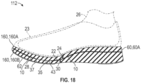
- an alternative article of footwear 112 has a midsole 160 that includes first and second foam layers 160A, 160B that are portions of a single component (i.e., a single, unitary, one-piece resilient foam midsole 160).
- the first and second resilient foam midsole layers 160A, 160B are an upper portion and a lower portion of a single resilient foam midsole 160 surrounding the sole plate 10, and in one embodiment, may be formed by injecting foam around the sole plate.
- the first and second foam layers 160A, 160B are the same material and have the same compressive stiffness.
- the first foam layer 160A overlays the through hole 35.
- the second foam layer 160B underlies the through hole 35.
- the first foam layer 60A and the second foam layer 60B resiliently deform under a dynamic compressive load, as shown for example in FIG. 17 , and return energy upon removal of the dynamic compressive load, returning to their steady state shapes as shown in FIG. 15 .
- the first foam layer 60A is compressed against the second foam layer 60B at the through hole 35 under the dynamic compressive load.
- a bottom surface 51 of the first foam layer 60A contacts a top surface 53 of the second foam layer 60B at the through hole 35 such that the first and second foam layers 60A, 60B are compressed against each other at the through hole 35.
- the first foam layer 60A and the second foam layer 60B are compressed against the sole plate 10 under the dynamic compressive load.
- the resilient deformation and the energy absorption of each of the first and second foam layers 60A, 60B is thus different at the through hole 35 than away from the through hole 35. For example, greater deformation of the foam layers 60A, 60B may be experienced at the through hole 35 than away from the through hole 35, as the foam layers may have less compressive stiffness than the sole plate.
- a softer cushioning feel may be experienced by a foot supported on the sole structure 14 at the through hole 35 (i.e., above the through hole) than away from the through hole.
- the first and second metatarsal heads 26A, 26B and the phalanges 26F, 26G of the hallux may thus experience greater cushioning.
- the sole plate 10 has a greater compressive stiffness than the first foam layer 60A and has a greater compressive stiffness than the second foam layer 60B.
- the sole plate 10 is one of a fiber strand-lain composite, a carbon-fiber composite, a thermoplastic elastomer, a glass-reinforced nylon, wood, or steel. Accordingly, the midsole system 15 is tuned to provide different energy return at the through hole 35 than away from the through hole 35. Dynamic compressive loading on the first resilient foam layer 60A is reacted with greater energy absorption at the through hole 35 where the first and second foam layers 60A. 60B interface with one another than away from the through hole 35 where the first and second resilient foam layers 60A, 60B react against and interface with the sole plate 10.
- the foam midsole 60 compresses between the foot 26 and the ground G under a dynamic compressive load and reacts against both the foot-facing surface 24 and the ground-facing surface 30 of the stiffer sole plate 10.
- the first foam layer 60A and the second foam layer 60B resiliently deform under the dynamic compressive load.
- the dynamic compressive load is illustrated by distributed loads F1, F2, F3, F4, F5 having various magnitudes represented by the length of the arrows.
- the first and second foam layers 60A, 60B return energy upon removal of the dynamic compressive load. Under dynamic loading, the first foam layer 60A is compressed against the foot-facing surface 24, and the second foam layer is compressed against the ground-facing surface 30.
- FIG. 12 shows the article of footwear in a resting position, under steady state loading by the foot 26.
- FIG. 12 may also represent an interim position of the article of footwear 12 during a stride in which the sole structure 14 is flat on the ground G.
- FIGS. 13-15 show the article of footwear 12 in progressive first, second, and third stages of motion during the stride.
- the first stage of motion show in FIG. 13 is the beginning of the stride, with the heel region 20 of the sole structure 14 and at least part of the midfoot region 18 lifted from the ground G and the forefoot region 16 in contact with the ground G.
- the second stage of motion in FIG. 14 shows further lifting of the midfoot region 18 of the sole structure 14 away from the ground surface G and the forefoot region 16 in contact with the ground G.
- FIG. 13 shows the article of footwear in a resting position, under steady state loading by the foot 26.
- FIG. 12 may also represent an interim position of the article of footwear 12 during a stride in which the sole structure 14 is flat on the ground G.
- the sole plate 10 bends along its length (e.g., along its longitudinal midline LM shown in FIG. 1 ). Progressive bending occurs in the forefoot region 16, generally under the metatarsal-phalangeal joints of the foot 26, when the foot 26 is dorsiflexed and increased loading is placed in the forefoot region 16 as the wearer's weight shifts to the forefoot.
- the hole 35 reduces the longitudinal bending stiffness of the sole plate 10 in the forefoot region 16 in comparison to a sole plate of the same thickness but without the hole.
- the spoon shape of the sole plate 10, best shown in FIG. 16 including the concave foot-facing surface 24 and convex ground-facing surface 30 in the forefoot region 16 helps to encourage forward rolling of the foot 26.
- the compressive forces in the sole plate 10 above a neutral axis of the sole plate 10 to the foot-facing surface 24, and tensile forces below the neutral axis to the ground-facing surface 30 are relieved, returning the sole plate 10 to its unloaded orientation shown in FIG. 15 , which is the same as in FIG. 12 except lifted from the ground.
- the internal compressive and tensile forces in the sole plate 10 due to the wearer bending the sole plate 10 are released as the sole plate 10 unbends creates a net force F at least partially in the forward direction.
- the sole plate 10 is tuned by varying its thickness, the amplitude of crests of ridges, and by the spoon shape, all of which contribute to the energy absorption during dynamic compression and longitudinal bending, and subsequent energy return during forward strides.
- longitudinal refers to a direction extending a length of a component.
- a longitudinal direction of a shoe extends between a forefoot region and a heel region of the shoe.
- the term “forward” is used to refer to the general direction from a heel region toward a forefoot region
- the term “rearward” is used to refer to the opposite direction, i.e., the direction from the forefoot region toward the heel region.
- a component may be identified with a longitudinal axis as well as a forward and rearward longitudinal direction along that axis.
- vertical refers to a direction generally perpendicular to both the lateral and longitudinal directions.
- the vertical direction may extend from the ground surface upward.
- each of these directional adjectives may be applied to individual components of a sole structure.
- upward or upwards refers to the vertical direction pointing towards a top of the component, which may include an instep, a fastening region and/or a throat of an upper.
- downward or downwards refers to the vertical direction pointing opposite the upwards direction, and may generally point towards the sole structure, or towards the outermost components of the sole structure.
- the "interior” of an article of footwear refers to portions at the space that is occupied by a wearer's foot when the shoe is worn.
- the “inner side” of a component refers to the side or surface of the component that is (or will be) oriented toward the interior of the shoe in an assembled shoe.
- the “outer side” or “exterior” of a component refers to the side or surface of the component that is (or will be) oriented away from the interior of the shoe in an assembled shoe.
- the inner side of a component may have other components between that inner side and the interior in the assembled shoe.
- an outer side of a component may have other components between that outer side and the space external to the assembled shoe.
- the terms “inward” and “inwardly” shall refer to the direction toward the interior of the component or article of footwear, such as a shoe, and the terms “outward” and “outwardly” shall refer to the direction toward the exterior of the component or article of footwear, such as the shoe.
- proximal refers to a direction that is nearer a center of a footwear component, or is closer toward a foot when the foot is inserted in the article as it is worn by a user.
- distal refers to a relative position that is further away from a center of the footwear component or is further from a foot when the foot is inserted in the article as it is worn by a user.
- proximal and distal may be understood to provide generally opposing terms to describe the relative spatial position of a footwear layer.
Description
- The present teachings generally include a sole plate for an article of footwear and a midsole system for an article of footwear.
- Footwear typically includes a sole structure configured to be located under a wearer's foot to space the foot away from the ground. Sole structures may typically be configured to provide one or more of cushioning, motion control, and resiliency.
US 2011/0271553 A1 describes a footwear including an upper and a sole assembly coupled to the upper, with the sole assembly including an outsole with a ground-contacting surface and a midsole positioned above the outsole. The midsole includes a peripheral lasting member that defines a central aperture, and a cushioning member positioned at least above the peripheral lasting member. -
DE 19641866 A1 describes a footwear including an upper and a sole assembly coupled to the upper, with the sole assembly including an outsole and a midsole, wherein the midsole comprises a corrugated structure, i.e. the upper surface presents ridges while the opposite face presents groves aligned with the aforementioned ridges. -
-
FIG. 1 is a schematic illustration in plan view of a foot-facing surface of a sole plate having a through hole. -
FIG. 2 is a schematic illustration in plan view of a ground-facing surface of the sole plate ofFIG. 1 . -
FIG. 3 is a schematic illustration in lateral side view of the sole plate ofFIG. 1 . -
FIG. 4 is a schematic illustration in medial side view of the sole plate ofFIG. 1 . -
FIG. 5 is a schematic illustration in front view of the sole plate ofFIG. 1 . -
FIG. 6 is a schematic illustration in rear view of the sole plate ofFIG. 1 . -
FIG. 7 is a schematic cross-sectional illustration of the sole plate ofFIG. 1 taken at lines 7-7 inFIG. 1 . -
FIG. 8 is a schematic cross-sectional illustration of the sole plate ofFIG. 1 taken at lines 8-8 inFIG. 1 . -
FIG. 9 is a schematic cross-sectional illustration of the sole plate ofFIG. 1 taken at lines 9-9 inFIG. 1 . -
FIG. 10 is a schematic cross-sectional illustration of the sole plate ofFIG. 1 taken at lines 10-10 inFIG. 1 . -
FIG. 11 is a schematic cross-sectional illustration of the sole plate ofFIG. 1 taken at lines 11-11 inFIG. 1 . -
FIG. 12 is a schematic illustration in medial side view of an article of footwear having a sole structure with a midsole system that includes the sole plate ofFIG. 1 , with the sole plate shown in hidden lines. -
FIG. 13 is a schematic illustration in medial side view of the article of footwear ofFIG. 12 , in a first stage of motion. -
FIG. 14 is a schematic illustration in medial side view of the article of footwear ofFIG. 12 , in a second stage of motion. -
FIG. 15 is a schematic illustration in medial side view of the article of footwear ofFIG. 12 , in a third stage of motion. -
FIG. 16 is a schematic illustration in cross-sectional view of the article of footwear ofFIG. 12 taken at lines 16-16 inFIG. 12 . -
FIG. 17 is a schematic fragmentary cross-sectional illustration of a forefoot portion of the article of footwear ofFIG. 16 when in the second stage of motion ofFIG. 14 . -
FIG. 18 is a schematic illustration in cross-sectional view of an alternative of footwear having an alternative embodiment of a midsole system with the sole plate ofFIG. 1 . - A sole structure for an article of footwear comprises a midsole system according to claim 1. Particular embodiments are disclosed in dependent claims 2 to 15.
- In one or more embodiments, the through hole may have an irregular shape that tapers in width in a forward direction. The through hole may be configured to underlie first and second metatarsal heads and a hallux of a wearer.
- In one or more embodiments, the midsole system may further include a first foam layer secured to the foot-facing surface and overlaying the through hole. The midsole system may also include a second foam layer secured to the ground-facing surface and underlying the through hole. The first foam layer and the second foam layer may resiliently deform under a dynamic compressive load and may return energy upon removal of the dynamic compressive load. The first foam layer may be compressed against the second foam layer at the through hole under the dynamic compressive load. The first foam layer and the second foam layer may be compressed against the sole plate away from the through hole under the dynamic compressive load. The resilient deformation and the energy absorption may thus be different at the through hole than away from the through hole. For example, greater deformation may be experienced at the through hole as the foam layers may have less compressive stiffness than the sole plate. A softer cushioning feel may be experienced by a foot supported on the sole structure at the through hole (i.e., above the through hole) than away from the through hole.
- The first and second foam layers may be portions of a single component, such as a unitary resilient foam midsole in which the sole plate is embedded. For example, the first and second resilient foam midsole layers may be an upper portion and a lower portion of a single resilient foam midsole surrounding the sole plate, and in one embodiment, may be formed by injecting foam around the sole plate. Alternatively, the first and second foam layers may be separate layers having different compressive stiffnesses. The first foam layer may be stiffer than the second foam layer, or may be less stiff than the second foam layer. The first foam layer and the second foam layer may be the same material or may be different materials.
- In one or more embodiments, the sole plate may have a greater compressive stiffness than the first foam layer and may have a greater compressive stiffness than the second foam layer. For example, in one or more embodiments, the sole plate may be one of a fiber strand-lain composite, a carbon-fiber composite, a thermoplastic elastomer, a glass-reinforced nylon, wood, or steel. Accordingly, the midsole system may be tuned to provide different energy return at the through hole than away from the through hole. Dynamic compressive loading on the first resilient sole layer may be reacted with greater energy absorption at the through hole where the first and second foam layers interact with one another than away from the through hole where the first and second resilient sole layers react against the sole plate.
- The sole plate may be tuned for stiffness, energy absorption, and direction of energy return with any or all of a varying thickness, non-parallel, longitudinally-extending ridges, and a generally spoon-shaped forefoot portion. In one or more embodiments, the foot-facing surface may be concave in a longitudinal direction of the sole plate in the forefoot region, and the ground-facing surface may be convex in the longitudinal direction of the sole plate in the forefoot region. In one or more embodiments, the sole plate may further include a heel region, and may be a unitary, one-piece component. Additionally, the sole plate may slope in the longitudinal direction in the midfoot region from the heel region to the forefoot region. The sole plate may be biased to this spoon shape in the forefoot region. Bending of the sole plate in the longitudinal direction during dorsiflexion may store energy that is released after toe-off, with the sole plate unbending to its original biased, spoon shape at least partially in the direction of forward motion.
- In one or more embodiments, the foot-facing surface may have ridges extending longitudinally in the midfoot region and in the forefoot region. The ground-facing surface may have grooves extending longitudinally in correspondence with the ridges. The ridges and the grooves may be configured such that a thickness of the sole plate from the foot-facing surface to the ground-facing surface varies at a transverse cross-section the sole plate through the ridges, or varies along a length of at least one of the ridges, or varies at both the transverse cross-section and along the length of the at least one of the ridges. The ridges, grooves, and a varied thickness as described may tune the stiffness and energy absorption of the sole plate for different zones while permitting a unitary, one-piece component of uniform material. The sole plate may function as a stiffness modifier within the sole structure.
- In one or more embodiments, the ridges may have crests, and at least some of the crests may extend non-parallel with one another in a longitudinal direction of the sole plate. The grooves may also have crests, and at least some of the crests of the grooves may extend non-parallel with one another in the longitudinal direction. Because the ridges may be non-parallel, the wavelengths can be different at different transverse cross-sections through the sole plate. Generally, ridges with shorter wavelengths are stiffer in compression than ridges with longer wavelengths.
- In one or more embodiments, a lateral-most one of the ridges may curve in the longitudinal direction to follow a curved lateral edge of the sole plate, and a medial-most one of the ridges may curve in the longitudinal direction to follow a curved medial edge of the sole plate.
- In one or more embodiments, the ridges may have crests at least some of which vary in amplitude in a longitudinal direction of the sole plate such that the amplitude of the crests of the ridges is greater in a zone of the sole plate configured for relatively high compressive loads than in a zone of the sole plate configured for relatively low compressive loads. For example, at least some of the crests may have an amplitude that is greater in a rearward portion of the forefoot region than in a forward portion of the forefoot region, and also greater than in the midfoot region. The rearward portion may be configured to underlie the metatarsal-phalangeal joints of a wearer, thus increasing stiffness and energy-absorbing capability where loading is greatest.
- In one or more embodiments, the transverse cross-section may be a first transverse cross-section of the sole plate in the midfoot region, and the undulating profile of the sole plate at the first transverse cross-section may include a first set of multiple waves having crests at the ridges and having troughs between respective adjacent ones of the ridges. The undulating profile of the sole plate at a second transverse cross-section of the sole plate in the forefoot region may include a second set of multiple waves having crests at the ridges and having troughs between respective adjacent ones of the ridges. Waves of the first set may each have a first wavelength. Waves of the second set may each have a second wavelength greater than the first wavelength. A lateral-most one of the ridges may curve in the longitudinal direction to follow a curved lateral edge of the sole plate. A medial-most one of the ridges may curve in the longitudinal direction to follow a curved medial edge of the sole plate.
- In one or more embodiments, the sole plate may be a resilient material such that the crests of the ridges decrease in elevation from a steady state elevation to a loaded elevation under a dynamic compressive load and return to the steady state elevation upon removal of the dynamic compressive load. For example, the sole plate may be one of a fiber strand-lain composite, a carbon-fiber composite, a thermoplastic elastomer, a glass-reinforced nylon, wood, or steel. The sole plate may resiliently deform to absorb and return energy. The areas of greater amplitude can absorb more energy than those of less amplitude. When sandwiched between foam layers of less compressive stiffness, such as a resilient foam midsole layer overlying and underlying the sole plate, the foam layers may react against the sole plate when resiliently deforming, so that the sole plate acts as a moderator both of bending stiffness and compressive stiffness of the sole structure.
- In one or more embodiments, the foot-facing surface may have an undulating profile at the transverse cross-section that includes multiple waves having crests at the ridges and having troughs between respective adjacent ones of the ridges. The crests at the ridges may be aligned with crests of the grooves. The thickness of the sole plate at the transverse cross-section may be less at the crests of the ridges than between the crests of the ridges and the troughs. The ground-facing surface may be flat between the grooves at the transverse cross-section.
- In an aspect of the disclosure, a sole structure for an article of footwear may comprise a midsole system including a sole plate having a forefoot region and a midfoot region. The sole plate has a foot-facing surface and a ground-facing surface opposite to the foot-facing surface. The foot-facing surface may be concave in a longitudinal direction of the sole plate in the forefoot region, and the ground-facing surface may be convex in the longitudinal direction of the sole plate in the forefoot region. The sole plate may define a through hole extending from the foot-facing surface to the ground-facing surface in the forefoot region. The through hole may have an irregular shape that tapers in width in a forward direction and may be closer to a medial edge of the sole plate than to a lateral edge of the sole plate. The midsole system may include a first foam layer secured to the foot-facing surface and overlaying the through hole. The midsole system may also include a second foam layer secured to the ground-facing surface and underlying the through hole. The first foam layer and the second foam layer may resiliently deform under the dynamic compressive load and may return energy upon removal of the dynamic compressive load. The first foam layer may be compressed against the second foam layer at the through hole during dynamic compressive loading. The first foam layer and the second foam layer may be compressed against the sole plate away from the through hole. The resilient deformation and the energy absorption may thus be different at the through hole than away from the through hole.
- In one or more embodiments, the foot-facing surface may have ridges extending longitudinally in the midfoot region and in the forefoot region, and the ground-facing surface may have grooves extending longitudinally in correspondence with the ridges. The ground-facing surface may be flat between the grooves at the transverse cross-section. The ridges and the grooves may be configured such that a thickness of the sole plate from the foot-facing surface to the ground-facing surface may vary at a transverse cross-section of the sole plate through the ridges, or may vary along a length of at least one of the ridges, or may vary at both the transverse cross-section and along the length of the at least one of the ridges.
- In one or more embodiments, the ridges may have crests, and at least some of the crests may vary in amplitude in a longitudinal direction of the sole plate such that the amplitude may be greater in a zone of the sole plate configured for relatively high compressive loads than in a zone of the sole plate configured for relatively low compressive loads.
- In one or more embodiments, the sole plate may have a compressive stiffness that is greater than that of the first foam layer and greater than that of the second foam layer.
- The above features and advantages and other features and advantages of the present teachings are readily apparent from the following detailed description of the modes for carrying out the present teachings when taken in connection with the accompanying drawings.
- Referring to the drawings, wherein like reference numbers refer to like components throughout the views,
FIG. 1 shows an embodiment of asole plate 10 for an article offootwear 12, such as the article offootwear 12 ofFIG. 10 . More specifically, thesole plate 10 is included in asole structure 14 of the article offootwear 12. Thesole structure 14 has amidsole system 15 that includes thesole plate 10 and aresilient foam midsole 60 including first and second foam layers 60A, 60B. The foam layers 60A, 60B interact with thesole plate 10 and with one another at a strategically positioned throughhole 35 in thesole plate 10 as discussed herein to provide tuned energy absorption and return that is different at the through hole than away from the throughhole 35. Thesole plate 10 described herein is configured to moderate bending stiffness during dorsiflexion, and direct return energy to the foot at least partially in a forward direction when dynamic compressive loading is removed following dorsiflexion during a stride. More specifically, thesole plate 10 deforms when under a dynamic load storing elastic energy, but resiliently returns to an unloaded state when the dynamic load is removed, releasing the stored elastic energy. - As used herein, the term "plate", such as in
sole plate 10, refers to a member of a sole structure that has a width greater than its thickness and is generally horizontally disposed when assembled in an article of footwear that is resting on the sole structure on a level ground surface, so that its thickness is generally in the vertical direction and its width is generally in the horizontal direction. A plate need not be a single component but instead can be multiple interconnected components. Portions of a plate can be flat, and portions can have some amount of curvature and variations in thickness when molded or otherwise formed in order to provide a shaped footbed and/or increased thickness for reinforcement in desired areas. - With reference to
FIG. 1 , thesole plate 10 has aforefoot region 16, amidfoot region 18, and aheel region 20, and as such is referred to as a full-lengthsole plate 10 and is a unitary, one-piece component. Alternatively, in other embodiments within the scope of the present teachings, thesole plate 10 could include only aforefoot region 16 andmidfoot region 18, or only amidfoot region 18 andheel region 20. - When a
human foot 26 of a size corresponding with the sole structure 14 (seeFIG. 13 ) is supported on the sole structure, theforefoot region 16 generally includes portions of thesole plate 10 corresponding with the toes and the joints connecting the metatarsals with the phalanges of the human foot (interchangeably referred to herein as the "metatarsal-phalangeal joints" or "MPJ" joints). Themidfoot region 18 generally includes portions of thesole plate 10 corresponding with an arch area of thefoot 26, including the navicular joint. Theheel region 20 generally includes portions of a sole plate corresponding with rear portions of thefoot 26, including the calcaneus bone. Theforefoot region 16, themidfoot region 18, and theheel region 20 may also be referred to as a forefoot portion, a midfoot portion, and a heel portion, respectively, and may also be used to refer to corresponding regions of an upper 23 shown inFIG. 12 and other components of the article offootwear 12. Themidfoot region 18 is disposed between theforefoot region 16 and theheel region 20 such that theforefoot region 16 is forward of (i.e., anterior to) themidfoot region 18 and the heel region is rearward of (i.e., posterior to) themidfoot region 18. - The
sole plate 10 has afirst side 22 shown inFIG. 1 , also referred to as a foot-facingside 22 that includes a foot-facingsurface 24. As shown inFIG. 2 , thesole plate 10 also has asecond side 28 referred to as a ground-facingside 28 that includes a ground-facingsurface 30. The foot-facingside 22 is closer to the foot 26 (shown in phantom inFIG. 16 ) than is the ground-facingside 28 when thesole plate 10 is assembled in the article offootwear 12 and worn on afoot 26. The foot-facingside 22 is above the ground-facingside 28 when thesole plate 10 is assembled in the article offootwear 12 and worn on thefoot 26. Thesole plate 10 also has a curvedlateral edge 34 and a curvedmedial edge 32. Thesole plate 10 is a sole plate for a right foot. It should be understood that a sole plate for a left foot is a mirror image of thesole plate 10. - The
sole plate 10 defines a throughhole 35 extending from the foot-facingsurface 24 to the ground-facingsurface 30 in theforefoot region 16. The throughhole 35 is closer to amedial edge 32 of the sole plate than to alateral edge 34 of the sole plate. More of the throughhole 35 is disposed between themedial edge 32 and the longitudinal midline LM than between thelateral edge 34 and the longitudinal midline LM. Additionally, the through hole has an irregular shape that tapers in width in a forward direction. The irregular shape is defined by the continuous edge 33 of thesole plate 10 bordering and defining the throughhole 35, including amedial extremity 39, alateral extremity 41, a relatively widerear edge 43, and a narrow, peakedforward extremity 37. The continuous edge 33 is a smooth, curved edge, without any corners or angles. The throughhole 35 tapers in width from themedial extremity 39 and thelateral extremity 41 in the forward direction. The peakedforward extremity 37 is closer to themedial extremity 39 than to thelateral extremity 41, making the throughhole 35 asymmetrical. Some of the bones of thefoot 26 are shown in phantom inFIG. 2 overlying thesole plate 10. The metatarsal heads are partially shown in phantom including thefirst metatarsal head 26A, thesecond metatarsal head 26B, thethird metatarsal head 26C, thefourth metatarsal head 26D, and thefifth metatarsal head 26E. The hallux is represented byphalanges hole 35, the throughhole 35 is configured to underlie first and second metatarsal heads 26A, 26B and thehallux sole plate 10 and the article offootwear 12, such as based on population averages. - Referring to
FIG. 1 , the foot-facingsurface 24 has ridges 40 extending longitudinally in themidfoot region 18 and in theforefoot region 16. The ridges 40 do not extend to theheel region 20. The foot-facingsurface 24 is generally flat in theheel region 20 as best shown inFIGS. 10 and 11 . The ground-facingsurface 30 has grooves 42 extending longitudinally in correspondence with the ridges 40. In the embodiment shown, there are four ridges 40 and four grooves 42. More specifically, as best shown inFIGS. 7-9 , there are fourridges medial edge 32 and thelateral edge 34. Theridges ridges 40D curves in the longitudinal direction to follow the curvedlateral edge 34, and the medial-most one of theridges 40A curves in the longitudinal direction to follow the curvedmedial edge 32. Stated differently, theridge 40D curves relative to a longitudinal midline LM to generally follow thelateral edge 34, and theridge 40A curves relative to the longitudinal midline LM to generally follow themedial edge 32. The longitudinal direction is generally a direction along a longitudinal midline LM of thesole plate 10, and may be either a forward direction (i.e., from themidfoot region 18 toward the forefoot region 16), or a rearward direction (i.e., from theforefoot region 16 toward the midfoot region 18). - With reference to
FIGS. 3 and 4 , the foot-facingsurface 24 is concave in a longitudinal direction of thesole plate 10 in theforefoot region 16, and the ground-facingsurface 30 is convex in the longitudinal direction of thesole plate 10 in theforefoot region 16. The concavity of the foot-facingsurface 24 and the convexity of the ground-facingsurface 30 extend into themidfoot region 18 so that themidfoot region 18 and theforefoot region 16 together establish a spoon shape. Additionally, thesole plate 10 slopes in the longitudinal direction in themidfoot region 18 from theheel region 20 to theforefoot region 16. More specifically, themidfoot region 18 slopes downward from theheel region 20 to theforefoot region 16 when thesole plate 10 is assembled in thesole structure 14 and thesole structure 14 rests on a level ground surface G as shown inFIG. 12 .FIGS. 5 and 6 also illustrate the concavity of the foot-facingsurface 24 and the convexity of the ground-facingsurface 30 in theforefoot region 16. InFIGS. 5 and 6 , thesole plate 10 is shown with the lowest point resting on a level ground surface G (i.e., prior to installation in the sole structure 14). Thesole plate 10 slopes downward in theforefoot region 16 from afront edge 36. Thesole plate 10 slopes down in themidfoot region 18 relative to theheel region 20 which is level with arear edge 38. Thefront edge 36 is higher than therear edge 38 when in this position. - As used herein, a transverse cross-section of the
sole plate 10 through the ridges 40 is a cross-section perpendicular to the longitudinal midline LM, such as the cross-sections ofFIGS. 7-11 . As best shown inFIGS. 7-9 , at any particular transverse cross-section of thesole plate 10 through theridges crests adjacent crests lateral edge 34 and themedial edge 32 varies along the length of the sole plate 10 (i.e., thesole plate 10 has different widths at different transverse cross-sections), thecrests sole plate 10. - With reference to
FIG. 2 , there are fourgrooves surface 30, in order, between themedial edge 32 and thelateral edge 34. As is apparent inFIG. 2 , thegrooves heel region 20, and the ground-facingsurface 30 is generally flat in theheel region 20. The ridges 40 and the grooves 42 extend only in themidfoot region 18 and theforefoot region 16. Thegrooves grooves 42D curves in the longitudinal direction to follow the curvedlateral edge 34, and the medial-most one of thegrooves 42A curves in the longitudinal direction to follow the curvedmedial edge 32. Stated differently, thegroove 42D curves relative to the longitudinal midline LM to generally follow thelateral edge 34, and thegroove 42A curves relative to the longitudinal midline LM to follow themedial edge 32. Likecrests sole plate 10 through theridges crests adjacent crests crests sole plate 10. - The
crests grooves crests ridges crests crests crests ridge line connecting crest 44A andcrest 46A) is perpendicular to a line along the flat portions of the ground-facingsurface 30 at the transverse cross-section. As is apparent inFIGS. 1-2 , and5-9 , the ground-facingsurface 30 of thesole plate 10 is flat between the grooves 42 at any transverse cross-section. - Due to the ridges 40 and the grooves 42, the
sole plate 10 has an undulating profile at any transverse cross-section of thesole plate 10 through the ridges 40. For example, the transverse cross-section ofFIG. 9 is a first transverse cross-section of thesole plate 10 in themidfoot region 18. The foot-facingsurface 24 has an undulating profile P1 of the sole plate at the first transverse cross-section. The undulating profile P1 includes a first set of multiple waves W1, W2, W3, W4 having crests 44A, 44B, 44C, 44D at theridges troughs - The transverse cross-section at
FIG. 7 is a second transverse cross-section of thesole plate 10 through the ridge 40 in theforefoot region 16. The undulating profile P2 of thesole plate 10 at the second transverse cross-section includes a second set of multiple waves W1A, W2A, W3A,W4A having crests ridges troughs medial edge 32 to the lateral edge 34) at the second transverse cross-section. - A third transverse cross-section of the
sole plate 10 across the ridges 40 is shown inFIG. 8 and is positioned longitudinally between the first and second cross-sections ofFIGS. 9 and 7 . The undulating profile P3 of thesole plate 10 at the third transverse cross-section includes a third set of multiple waves W1B, W2B, W3B, W4B having thecrests ridges troughs sole plate 10 at the third transverse cross-section being greater than that at the first transverse cross-section and greater than that at the second transverse cross-section. Generally, increasing the number of ridges 40 over a given width (i.e., decreasing the wavelength) increases the bending stiffness in the longitudinal direction of thesole plate 10. Thesole plate 10 is wider in theforefoot region 16 at the third transverse cross-section ofFIG. 8 than in themidfoot region 18 at the first transverse cross-section ofFIG. 9 . Because the ridges 40 are nonparallel and the wavelengths of the waves at a given transverse cross-section are equal, thesole plate 10 has the same number of ridges (four) over theforefoot region 16 andmidfoot region 18. - In addition to the number of ridges 40, the thickness of the
sole plate 10 and the amplitude of thecrests sole plate 10. When the crests 44A, 44B, 44C, 44D are referred to generally herein, the reference numeral 44 may be used. The ridges 40 and the grooves 42 are configured such that a thickness of thesole plate 10 from the foot-facingsurface 24 to the ground-facingsurface 30 varies at a transverse cross-section of thesole plate 10 through the ridges 40 and varies along a length of at least one of the ridges 40. For example, as shown at the transverse cross-section inFIG. 8 , the thickness T1 of thesole plate 10 at the crests 44 of the ridges 40 (as shown atcrest 44D) is less than the thickness T2 of thesole plate 10 at a location between the crests of the ridges and the troughs. Thesole plate 10 will thus tend to elastically deform under a compressive load applied to the foot-facingsurface 24 beginning at the crests 44. For example, thesole plate 10 may be a resilient material such that the foot-facingsurface 24 including the crests 44 of the ridges 40 decreases in elevation under a dynamic compressive load from the steady state elevation shown with solid lines inFIG. 8 to a loadedelevation 24A shown in phantom inFIG. 8 , and returns to the steady state elevation upon removal of the dynamic compressive load. At thecrest 44C, for example, the elevation decreases from elevation E1 to elevation E2. For example, thesole plate 10 may be a fiber strand-lain composite, a carbon-fiber composite, a thermoplastic elastomer, a glass-reinforced nylon, wood, steel, or combinations thereof. - The ability of and the degree to which the
sole plate 10 elastically deforms is also tuned by varying the thickness of thesole plate 10 along the length of the ridges 40, and by varying the amplitude of the crests 44 along the length of the ridges 40. A comparison of the transverse cross-sections ofFIGS. 7-11 shows that thesole plate 10 is thinnest (i.e., has the least thickness) at the ridges 40 where the amplitude of the crests 44 is the highest (e.g., inFIG. 8 ), and the thickens gradually at the crests 44 as the amplitude decreases, as can be seen inFIGS. 7 and 9 . - The ability of and the degree to which the
sole plate 10 elastically deforms is tuned by varying the thickness of thesole plate 10 along the length of the ridges 40, and by varying the amplitude of the crests 44 along the length of the ridges 40. When the crests 46A, 46B, 46C, 46D are referred to generally herein, the reference numeral 46 may be used. The amplitude of the crests 46 is greater in zones of thesole plate 10 configured for relatively high compressive loads than in zones of thesole plate 10 configured for relatively low compressive loads. For example, referring toFIG. 1 , at least some of the crests 46 may have an amplitude that is greater in arearward portion 16A of the forefoot region 16 (e.g., including at the transverse cross-section ofFIG. 8 ) than in aforward portion 16B of the forefoot region (e.g., including at the transverse cross-section ofFIG. 7 ), and than in the midfoot region (e.g., including at the transverse cross-section ofFIG. 9 ). The greater amplitude of the crests 46 enables greater energy absorption under sufficient dynamic loading as more elastic deformation can occur with a greater possible change in height of the crests 46 between a steady state elevation and a loaded elevation. In the embodiment of thesole plate 10, the amplitude of the crests 44 at any given transverse cross-section is uniform. Stated differently, each of thecrests FIG. 7 , has the same amplitude at the cross-section ofFIG. 8 (although different from that atFIG. 7 ), and has the same amplitude at the cross-section ofFIG. 9 (although different from that atFIGS. 7 and 8 ). - Referring to
FIG. 12 , thesole structure 14 includes aresilient foam midsole 60. Thesole structure 14 also includesdiscrete outsole elements 62, or alternatively, could include a unitary outsole. Themidsole 60 includes a first foam layer 60A secured to the foot-facingsurface 24, and a second foam layer 60B secured to the ground-facingsurface 30. The first and second foam layers 60A, 60B are separate components having different compressive stiffnesses. The first foam layer 60A may be more or less stiff than the second foam layer 60B. The first foam layer 60A and the second foam layer 60B may be the same material composition, with different densities to provide the different compressive stiffnesses, or may be different materials. - Alternatively, as shown in
FIG. 18 , an alternative article offootwear 112 has a midsole 160 that includes first and second foam layers 160A, 160B that are portions of a single component (i.e., a single, unitary, one-piece resilient foam midsole 160). The first and second resilient foam midsole layers 160A, 160B are an upper portion and a lower portion of a single resilient foam midsole 160 surrounding thesole plate 10, and in one embodiment, may be formed by injecting foam around the sole plate. The first and second foam layers 160A, 160B are the same material and have the same compressive stiffness. - The first foam layer 160A overlays the through
hole 35. The second foam layer 160B underlies the throughhole 35. The first foam layer 60A and the second foam layer 60B resiliently deform under a dynamic compressive load, as shown for example inFIG. 17 , and return energy upon removal of the dynamic compressive load, returning to their steady state shapes as shown inFIG. 15 . The first foam layer 60A is compressed against the second foam layer 60B at the throughhole 35 under the dynamic compressive load. For example, as shown inFIG. 17 , abottom surface 51 of the first foam layer 60A contacts atop surface 53 of the second foam layer 60B at the throughhole 35 such that the first and second foam layers 60A, 60B are compressed against each other at the throughhole 35. Away from the through hole 35 (i.e., where thelower surface 51 of the first resilient foam layer 60A is secured to the foot-facingsurface 24, and where theupper surface 53 of the second foam layer 60B is secured to the ground-facing surface 30), the first foam layer 60A and the second foam layer 60B are compressed against thesole plate 10 under the dynamic compressive load. The resilient deformation and the energy absorption of each of the first and second foam layers 60A, 60B is thus different at the throughhole 35 than away from the throughhole 35. For example, greater deformation of the foam layers 60A, 60B may be experienced at the throughhole 35 than away from the throughhole 35, as the foam layers may have less compressive stiffness than the sole plate. A softer cushioning feel may be experienced by a foot supported on thesole structure 14 at the through hole 35 (i.e., above the through hole) than away from the through hole. The first and second metatarsal heads 26A, 26B and thephalanges - In one or more embodiments, the
sole plate 10 has a greater compressive stiffness than the first foam layer 60A and has a greater compressive stiffness than the second foam layer 60B. For example, in one or more embodiments, thesole plate 10 is one of a fiber strand-lain composite, a carbon-fiber composite, a thermoplastic elastomer, a glass-reinforced nylon, wood, or steel. Accordingly, themidsole system 15 is tuned to provide different energy return at the throughhole 35 than away from the throughhole 35. Dynamic compressive loading on the first resilient foam layer 60A is reacted with greater energy absorption at the throughhole 35 where the first and second foam layers 60A. 60B interface with one another than away from the throughhole 35 where the first and second resilient foam layers 60A, 60B react against and interface with thesole plate 10. - As indicated in
FIG. 17 , thefoam midsole 60 compresses between thefoot 26 and the ground G under a dynamic compressive load and reacts against both the foot-facingsurface 24 and the ground-facingsurface 30 of the stiffersole plate 10. The first foam layer 60A and the second foam layer 60B resiliently deform under the dynamic compressive load. The dynamic compressive load is illustrated by distributed loads F1, F2, F3, F4, F5 having various magnitudes represented by the length of the arrows. The first and second foam layers 60A, 60B return energy upon removal of the dynamic compressive load. Under dynamic loading, the first foam layer 60A is compressed against the foot-facingsurface 24, and the second foam layer is compressed against the ground-facingsurface 30. -
FIG. 12 shows the article of footwear in a resting position, under steady state loading by thefoot 26.FIG. 12 may also represent an interim position of the article offootwear 12 during a stride in which thesole structure 14 is flat on the ground G.FIGS. 13-15 show the article offootwear 12 in progressive first, second, and third stages of motion during the stride. The first stage of motion show inFIG. 13 is the beginning of the stride, with theheel region 20 of thesole structure 14 and at least part of themidfoot region 18 lifted from the ground G and theforefoot region 16 in contact with the ground G. The second stage of motion inFIG. 14 shows further lifting of themidfoot region 18 of thesole structure 14 away from the ground surface G and theforefoot region 16 in contact with the ground G. Finally,FIG. 15 shows the article offootwear 12 completely lifted away from the ground G, as may occur during running. During the stride, thesole plate 10 bends along its length (e.g., along its longitudinal midline LM shown inFIG. 1 ). Progressive bending occurs in theforefoot region 16, generally under the metatarsal-phalangeal joints of thefoot 26, when thefoot 26 is dorsiflexed and increased loading is placed in theforefoot region 16 as the wearer's weight shifts to the forefoot. Thehole 35 reduces the longitudinal bending stiffness of thesole plate 10 in theforefoot region 16 in comparison to a sole plate of the same thickness but without the hole. - The spoon shape of the
sole plate 10, best shown inFIG. 16 , including the concave foot-facingsurface 24 and convex ground-facingsurface 30 in theforefoot region 16 helps to encourage forward rolling of thefoot 26. When thefoot 26 lifts thesole structure 14 away from the ground G inFIG. 15 , the compressive forces in thesole plate 10 above a neutral axis of thesole plate 10 to the foot-facingsurface 24, and tensile forces below the neutral axis to the ground-facingsurface 30 are relieved, returning thesole plate 10 to its unloaded orientation shown inFIG. 15 , which is the same as inFIG. 12 except lifted from the ground. The internal compressive and tensile forces in thesole plate 10 due to the wearer bending thesole plate 10 are released as thesole plate 10 unbends creates a net force F at least partially in the forward direction. - Accordingly, as discussed herein the
sole plate 10 is tuned by varying its thickness, the amplitude of crests of ridges, and by the spoon shape, all of which contribute to the energy absorption during dynamic compression and longitudinal bending, and subsequent energy return during forward strides. - To assist and clarify the subsequent description of various embodiments, various terms are defined herein. Unless otherwise indicated, the following definitions apply throughout this specification (including the claims).
- "A", "an", "the", "at least one", and "one or more" are used interchangeably to indicate that at least one of the items is present. A plurality of such items may be present unless the context clearly indicates otherwise. As used herein, "at least some" of an item means at least two of the items. All numerical values of parameters (e.g., of quantities or conditions) in this specification, unless otherwise indicated expressly or clearly in view of the context, including the appended claims, are to be understood as being modified in all instances by the term "about" whether or not "about" actually appears before the numerical value. "About" indicates that the stated numerical value allows some slight imprecision (with some approach to exactness in the value; approximately or reasonably close to the value; nearly). If the imprecision provided by "about" is not otherwise understood in the art with this ordinary meaning, then "about" as used herein indicates at least variations that may arise from ordinary methods of measuring and using such parameters. In addition, a disclosure of a range is to be understood as specifically disclosing all values and further divided ranges within the range. All references referred to are incorporated herein in their entirety.
- The terms "comprising", "including", and "having" are inclusive and therefore specify the presence of stated features, steps, operations, elements, or components, but do not preclude the presence or addition of one or more other features, steps, operations, elements, or components. Orders of steps, processes, and operations may be altered when possible, and additional or alternative steps may be employed. As used in this specification, the term "or" includes any one and all combinations of the associated listed items. The term "any of" is understood to include any possible combination of referenced items, including "any one of" the referenced items. The term "any of" is understood to include any possible combination of referenced claims of the appended claims, including "any one of" the referenced claims.
- For consistency and convenience, directional adjectives are employed throughout this detailed description corresponding to the illustrated embodiments. Those having ordinary skill in the art will recognize that terms such as "above", "below", "upward", "downward", "top", "bottom", etc., may be used descriptively relative to the figures, without representing limitations on the scope of the invention, as defined by the claims.
- The term "longitudinal", as used throughout this detailed description and in the claims, refers to a direction extending a length of a component. For example, a longitudinal direction of a shoe extends between a forefoot region and a heel region of the shoe. The term "forward" is used to refer to the general direction from a heel region toward a forefoot region, and the term "rearward" is used to refer to the opposite direction, i.e., the direction from the forefoot region toward the heel region. In some cases, a component may be identified with a longitudinal axis as well as a forward and rearward longitudinal direction along that axis.
- The term "vertical", as used throughout this detailed description and in the claims, refers to a direction generally perpendicular to both the lateral and longitudinal directions. For example, in cases where a sole structure is planted flat on a ground surface, the vertical direction may extend from the ground surface upward. It will be understood that each of these directional adjectives may be applied to individual components of a sole structure. The term "upward" or "upwards" refers to the vertical direction pointing towards a top of the component, which may include an instep, a fastening region and/or a throat of an upper. The term "downward" or "downwards" refers to the vertical direction pointing opposite the upwards direction, and may generally point towards the sole structure, or towards the outermost components of the sole structure.
- The "interior" of an article of footwear, such as a shoe, refers to portions at the space that is occupied by a wearer's foot when the shoe is worn. The "inner side" of a component refers to the side or surface of the component that is (or will be) oriented toward the interior of the shoe in an assembled shoe. The "outer side" or "exterior" of a component refers to the side or surface of the component that is (or will be) oriented away from the interior of the shoe in an assembled shoe. In some cases, the inner side of a component may have other components between that inner side and the interior in the assembled shoe. Similarly, an outer side of a component may have other components between that outer side and the space external to the assembled shoe. Further, the terms "inward" and "inwardly" shall refer to the direction toward the interior of the component or article of footwear, such as a shoe, and the terms "outward" and "outwardly" shall refer to the direction toward the exterior of the component or article of footwear, such as the shoe. In addition, the term "proximal" refers to a direction that is nearer a center of a footwear component, or is closer toward a foot when the foot is inserted in the article as it is worn by a user. Likewise, the term "distal" refers to a relative position that is further away from a center of the footwear component or is further from a foot when the foot is inserted in the article as it is worn by a user. Thus, the terms proximal and distal may be understood to provide generally opposing terms to describe the relative spatial position of a footwear layer.
Claims (15)
- A sole structure (14) for an article of footwear (12) comprising:a midsole system (15) including:
a sole plate (10) having a forefoot region (16) and a midfoot region (18);wherein the sole plate (10) has a foot-facing surface (24) and a ground-facing surface (30) opposite to the foot-facing surface (24);wherein:characterised in thatthe foot-facing surface (24) has ridges (40) extending longitudinally in the midfoot region (18) and in the forefoot region (16);the ground-facing surface (30) has grooves (42) extending longitudinally in correspondence with the ridges (40); andthe ridges (40) and the grooves (42) are configured such that a thickness of the sole plate (10) from the foot-facing surface (24) to the ground-facing surface (30) varies at a transverse cross-section of the sole plate (10) through the ridges (40), or varies along a length of at least one of the ridges (40), or varies at both the transverse cross-section of the sole plate (10) through the ridges (40) and along the length of the at least one of the ridges (40),the sole plate (10) defines a through hole (35) extending from the foot-facing surface (24) to the ground-facing surface (30) in the forefoot region (16); andwherein the through hole(35) is closer to a medial edge (32) of the sole plate (19) than to a lateral edge (34) of the sole plate (10). - The sole structure (14) of claim 1, wherein the through hole (35) has an irregular shape that tapers in width in a forward direction.
- The sole structure (14) of any of claims 1-2, wherein the through hole (35) is configured to underlie first and second metatarsal heads and a hallux of a wearer.
- The sole structure (14) of any of claims 1-3, wherein the midsole system (15) further includes:a first foam layer (60A) secured to the foot-facing surface (24) and overlaying the through hole (35);a second foam layer (60B) secured to the ground-facing surface (30) and underlying the through hole (35);wherein the first foam layer (60A) and the second foam layer (60B) resiliently deform under a dynamic compressive load and return energy upon removal of the dynamic compressive load;wherein the first foam layer (60A) is compressed against the second foam layer (60B) at the through hole (35) under the dynamic compressive load; andwherein the first foam layer (60A) and the second foam layer (60B) are compressed against the sole plate (10) away from the through hole (35) under the dynamic compressive load.
- The sole structure (14) of claim 4, wherein the sole plate (10) has a compressive stiffness that is greater than that of the first foam layer (60A) and greater than that of the second foam layer (60B).
- The sole structure (14) of claim 5, wherein the sole plate (10) is one of a fiber strand-lain composite, a carbon-fiber composite, a thermoplastic elastomer, a glass-reinforced nylon, wood, or steel.
- The sole structure (14) of any of claims 1-6, wherein:the foot-facing surface (24) is concave in a longitudinal direction of the sole plate (10) in the forefoot region (16); andthe ground-facing surface (30) is convex in the longitudinal direction of the sole plate (10) in the forefoot region (16).
- The sole structure (14) of claim 7, wherein:the sole plate (10) further includes a heel region (20); andthe sole plate (10) slopes in the longitudinal direction in the midfoot region (18) from the heel region (20) to the forefoot region (16).
- The sole structure (14) of any one of claims 1-8, wherein:the ridges (40) have crests at least some of which extend non-parallel with one another in a longitudinal direction of the sole plate (10); andthe grooves (42) have crests at least some of which extend non-parallel with one another in the longitudinal direction.
- The sole structure (14) of claim 9, wherein:a lateral-most one of the ridges (40)curves in the longitudinal direction to follow a curved lateral edge of the sole plate (10); anda medial-most one of the ridges (40) curves in the longitudinal direction to follow a curved medial edge of the sole plate (10).
- The sole structure (14) of any one of claims 1-10, wherein the ridges (40) have crests at least some of which vary in amplitude in a longitudinal direction of the sole plate (10) such that the amplitude is greater in a zone of the sole plate (10) configured for relatively high compressive loads than in a zone of the sole plate (10) configured for relatively low compressive loads.
- The sole structure (14) of claim 11, wherein at least some of the crests have an amplitude that is greater in a rearward portion of the forefoot region (16) than in a forward portion of the forefoot region (16) and than in the midfoot region (18).
- The sole structure (14) of any one of claims 1-12, wherein the ridges (40) have crests, and the sole plate (10) is a resilient material such that the crests of the ridges (40) decrease in elevation from a steady state elevation to a loaded elevation under a dynamic compressive load and return to the steady state elevation upon removal of the dynamic compressive load.
- The sole structure (14) of any one of claims 1-13, wherein:the foot-facing surface (24) has an undulating profile at the transverse cross-section that includes multiple waves that have crests at the ridges (40) and that have troughs between respective adjacent ones of the ridges (40);the crests at the ridges (40) are aligned with crests of the grooves (42); andthe ground-facing surface (30) is flat between the grooves (42) at the transverse cross-section.
- The sole structure (14) of claim 14, wherein:the thickness of the sole plate (10) at the transverse cross-section is less at the crests of the ridges (40) than between the crests of the ridges (40) and the troughs; andthe sole plate (10) further includes a heel region (20), and is a unitary, one-piece component.
Applications Claiming Priority (2)
| Application Number | Priority Date | Filing Date | Title |
|---|---|---|---|
| US201862678499P | 2018-05-31 | 2018-05-31 | |
| PCT/US2019/029294 WO2019231593A1 (en) | 2018-05-31 | 2019-04-26 | Footwear sole plate with forefoot through hole |
Publications (2)
| Publication Number | Publication Date |
|---|---|
| EP3801105A1 EP3801105A1 (en) | 2021-04-14 |
| EP3801105B1 true EP3801105B1 (en) | 2024-01-24 |
Family
ID=66429656
Family Applications (1)
| Application Number | Title | Priority Date | Filing Date |
|---|---|---|---|
| EP19722434.8A Active EP3801105B1 (en) | 2018-05-31 | 2019-04-26 | Footwear sole plate with forefoot through hole |
Country Status (4)
| Country | Link |
|---|---|
| US (3) | US11006695B2 (en) |
| EP (1) | EP3801105B1 (en) |
| CN (2) | CN115969139A (en) |
| WO (1) | WO2019231593A1 (en) |
Families Citing this family (10)
| Publication number | Priority date | Publication date | Assignee | Title |
|---|---|---|---|---|
| US11006695B2 (en) * | 2018-05-31 | 2021-05-18 | Nike, Inc. | Footwear sole plate with forefoot through hole |
| EP3801108B1 (en) * | 2018-05-31 | 2023-04-19 | NIKE Innovate C.V. | Footwear sole plate with non-parallel waves of varying thickness |
| US20210315320A1 (en) * | 2019-10-18 | 2021-10-14 | Asics Corporation | Shoe |
| DE102020202237B4 (en) * | 2020-02-21 | 2023-05-17 | Adidas Ag | Sole comprising individually deflectable reinforcement elements, and shoe with such a sole |
| CN116669584A (en) * | 2020-08-31 | 2023-08-29 | 彪马欧洲公司 | Article of footwear made from engineered wood |
| US20220125158A1 (en) * | 2020-10-28 | 2022-04-28 | Puma SE | Articles of footwear with support structures |
| JP2022079271A (en) * | 2020-11-16 | 2022-05-26 | 株式会社アシックス | Sole and shoe |
| USD1010297S1 (en) | 2021-06-30 | 2024-01-09 | Puma SE | Shoe |
| CN114831386A (en) * | 2022-04-28 | 2022-08-02 | 李宁(中国)体育用品有限公司 | Spoon-shaped supporting plate and sole |
| US20230371644A1 (en) * | 2022-05-18 | 2023-11-23 | Shimano Inc. | Shoe sole |
Family Cites Families (78)
| Publication number | Priority date | Publication date | Assignee | Title |
|---|---|---|---|---|
| US1527371A (en) | 1923-02-15 | 1925-02-24 | Albert J Mullarky | Ventilated shoe |
| US1741419A (en) * | 1927-01-29 | 1929-12-31 | Shoe Products Inc | Shoe |
| US1704187A (en) | 1927-07-22 | 1929-03-05 | Hood Rubber Co Inc | Sole for boots and shoes |
| US1693911A (en) | 1928-06-19 | 1928-12-04 | Schmeer Jakob | Shoe |
| US2124819A (en) | 1937-08-23 | 1938-07-26 | Henry G Halloran | Shoe bottom filler |
| US2150779A (en) * | 1938-01-26 | 1939-03-14 | William H Nickerson | Arch support for shoes |
| FR1000966A (en) * | 1946-12-02 | 1952-02-18 | Arch support adaptable to shoes or shoes | |
| US4854057A (en) | 1982-02-10 | 1989-08-08 | Tretorn Ab | Dynamic support for an athletic shoe |
| US4439937A (en) * | 1982-07-26 | 1984-04-03 | Daswick Alexander C | Integrally cast shoe sole containing stiffener member |
| JPS59103605U (en) | 1982-12-28 | 1984-07-12 | 美津濃株式会社 | athletic shoe soles |
| US5052130A (en) | 1987-12-08 | 1991-10-01 | Wolverine World Wide, Inc. | Spring plate shoe |
| EP0373336B1 (en) | 1988-12-13 | 1992-12-30 | Helmut Mayer | Insert for a shoe |
| US5255451A (en) | 1988-12-14 | 1993-10-26 | Avia Group International, Inc. | Insert member for use in an athletic shoe |
| JPH067204A (en) | 1992-06-29 | 1994-01-18 | Koichi Saga | Insole for shoes |
| IT1274345B (en) | 1994-04-12 | 1997-07-17 | Nordica Spa | SOLE STRENGTHENING DEVICE, ESPECIALLY FOR SPORTS FOOTWEAR. |
| US5647145A (en) * | 1995-06-05 | 1997-07-15 | Russell; Brian | Sculptured athletic footwear sole construction |
| DE19641866A1 (en) * | 1996-05-30 | 1997-12-04 | Helmut Mayer | Shoe and process for its manufacture and use |
| IT1290354B1 (en) | 1997-02-07 | 1998-10-22 | Vibram Spa | BIOMECHANICAL SOLE |
| JP3238129B2 (en) | 1998-06-08 | 2001-12-10 | 美津濃株式会社 | Midsole structure for sports shoes |
| JP3207805B2 (en) | 1998-06-25 | 2001-09-10 | 美津濃株式会社 | Midsole structure for sports shoes |
| US6023861A (en) * | 1998-08-17 | 2000-02-15 | Calzaturificio S.C.A.A.P.A. Spa | Arch support for a sports shoe |
| JP3542756B2 (en) | 2000-02-25 | 2004-07-14 | 美津濃株式会社 | Midsole structure for sports shoes |
| FR2823076B1 (en) | 2001-04-09 | 2003-06-27 | Salomon Sa | FOOTWEAR REINFORCEMENT, PARTICULARLY SPORTS AND MORE SPECIALLY CROSS-COUNTRY SKIING, AND FOOTWEAR COMPRISING SUCH REINFORCEMENT |
| JP3653633B2 (en) | 2001-05-07 | 2005-06-02 | 文雄 菅原 | Footwear bottom |
| JP3947658B2 (en) | 2001-06-28 | 2007-07-25 | 美津濃株式会社 | Midsole structure for sports shoes |
| JP4906153B2 (en) | 2001-06-28 | 2012-03-28 | 美津濃株式会社 | Midsole structure for sports shoes |
| US6802138B2 (en) * | 2002-02-08 | 2004-10-12 | Wolverine World Wide, Inc. | Cushioning system for footwear and related method of manufacture |
| JP4038391B2 (en) * | 2002-05-29 | 2008-01-23 | 美津濃株式会社 | Sole structure of sports shoes |
| JP2005013718A (en) | 2003-06-05 | 2005-01-20 | Mizuno Corp | Sole structure for shoe |
| US7207125B2 (en) | 2003-11-26 | 2007-04-24 | Saucony, Inc. | Grid midsole insert |
| US7162815B2 (en) | 2004-03-31 | 2007-01-16 | Mizuno Corporation | Midsole structure for an athletic shoe |
| US7168187B2 (en) | 2004-06-01 | 2007-01-30 | Wolverine World Wide, Inc. | Footwear construction and related method of manufacture |
| EP1848294A1 (en) | 2005-02-15 | 2007-10-31 | Fila Luxembourg S.a.r.l. | Shoe with an adjustable sole |
| KR100647108B1 (en) * | 2005-10-10 | 2006-11-23 | 남시호 | Shoes |
| US7594345B2 (en) | 2005-10-12 | 2009-09-29 | Nike, Inc. | Article of footwear having sole with ribbed structure |
| JP4481940B2 (en) | 2006-02-06 | 2010-06-16 | 美津濃株式会社 | Insoles for shoes |
| US8453344B2 (en) | 2006-04-21 | 2013-06-04 | Asics Corporation | Shoe sole with reinforcing structure and shoe sole with shock-absorbing structure |
| US7832117B2 (en) | 2006-07-17 | 2010-11-16 | Nike, Inc. | Article of footwear including full length composite plate |
| JP4153002B2 (en) | 2006-08-30 | 2008-09-17 | 美津濃株式会社 | Middle foot structure of shoe sole assembly |
| US7946058B2 (en) | 2007-03-21 | 2011-05-24 | Nike, Inc. | Article of footwear having a sole structure with an articulated midsole and outsole |
| US7866063B2 (en) | 2007-06-14 | 2011-01-11 | Nike, Inc. | Article of footwear with shock absorbing heel system |
| DE202007013120U1 (en) | 2007-09-19 | 2007-12-20 | Cetec Ag | Insole with stiffening element |
| DE102008059030B4 (en) | 2008-11-26 | 2014-09-25 | Helmut Mayer Gbr Mbh | insole |
| US8850718B2 (en) * | 2009-09-23 | 2014-10-07 | Shoes For Crews, Llc | Shoe with support system |
| US9055781B2 (en) | 2009-10-08 | 2015-06-16 | Varithotics Co., Ltd. | Body balance device |
| US8479414B2 (en) | 2010-03-01 | 2013-07-09 | Nike, Inc. | Footwear insole |
| US9021721B2 (en) * | 2010-05-07 | 2015-05-05 | Ariat International, Inc. | Footwear |
| US20120096745A1 (en) | 2010-10-22 | 2012-04-26 | Andrew Donato | Shoe insole for metatarsal relief |
| EP2446763A1 (en) * | 2010-10-26 | 2012-05-02 | Vibram S.p.A. | Transpiring shoe's sole |
| CN201905336U (en) | 2010-12-28 | 2011-07-27 | 浙江奥康鞋业股份有限公司 | Ventilation insole |
| DE102011109274A1 (en) | 2011-08-03 | 2013-02-07 | Mayer GbR (Vertretungsberechtigter Gesellschafter: Herr Helmut Mayer, 88045 Friedrichshafen) | Sole chassis for shoes |
| US20130061494A1 (en) | 2011-09-13 | 2013-03-14 | Danner, Inc. | Footwear with sole assembly having midsole plate and heel insert and associated methods |
| GB2497340B (en) * | 2011-12-08 | 2014-12-31 | Footjacks Ltd | Footwear/insole for footwear |
| US9913510B2 (en) | 2012-03-23 | 2018-03-13 | Reebok International Limited | Articles of footwear |
| JP5465814B1 (en) * | 2012-05-10 | 2014-04-09 | 株式会社アシックス | Sole with outsole and midsole |
| US9629415B2 (en) | 2012-07-24 | 2017-04-25 | Nike, Inc. | Sole structure for an article of footwear |
| FR2993758B1 (en) | 2012-07-27 | 2015-03-27 | Salomon Sas | IMPROVED SHOE SHOE |
| US20140230272A1 (en) * | 2013-02-11 | 2014-08-21 | The Walking Company Holdings, Inc. | Cushioned Sole with Air Chamber and Resistance Protrusions |
| US20140250723A1 (en) * | 2013-03-07 | 2014-09-11 | Nike, Inc. | Flexible sole supports for articles of footwear |
| WO2014155511A1 (en) * | 2013-03-26 | 2014-10-02 | 株式会社アシックス | Shoe for indoor sports |
| JP2014236886A (en) | 2013-06-08 | 2014-12-18 | 美津濃株式会社 | Sole structure of shoe |
| RU2016108840A (en) | 2013-09-18 | 2017-10-23 | Десаррольо Интеграль Дель Мольде, С.Л. | Mold for the manufacture of shoe soles and soles made using this mold |
| US8826567B1 (en) * | 2014-01-16 | 2014-09-09 | Ukies LLC | Footwear with insole system |
| CH709288B1 (en) | 2014-02-19 | 2018-04-13 | On Clouds Gmbh | Sole construction for a flexible shoe. |
| US10010137B2 (en) | 2014-07-30 | 2018-07-03 | Nike, Inc. | Article of footwear with banking midsole with embedded resilient plate |
| WO2016196770A1 (en) * | 2015-06-02 | 2016-12-08 | Under Armour, Inc. | Footwear including lightweight sole structure providing enhanced comfort, flexibility and performance features |
| JP6310427B2 (en) | 2015-08-07 | 2018-04-11 | 美津濃株式会社 | Sole structure of shoes |
| WO2017058419A1 (en) | 2015-10-02 | 2017-04-06 | Nike Innovate C.V. | Plate with foam for footwear |
| CN205082769U (en) | 2015-11-10 | 2016-03-16 | 晋江飞扬鞋材有限公司 | Abrasion resistant shock absorption shoe sole |
| US10517350B2 (en) * | 2016-06-14 | 2019-12-31 | Nike, Inc. | Sole structure for an article of footwear having longitudinal extending bridge portions with an interwoven stiffness controlling device |
| US10010135B2 (en) * | 2016-06-30 | 2018-07-03 | Boot Royalty Company, L.P. | Comfort system for boots |
| CN205912979U (en) | 2016-08-21 | 2017-02-01 | 福建省中环腾达鞋服有限公司 | Wear -resisting sole of bradyseism |
| EP3629806B1 (en) | 2017-05-23 | 2023-09-20 | Nike Innovate C.V. | Sole structure for an article of footwear with undulating sole plate |
| CN207400404U (en) | 2017-06-15 | 2018-05-25 | 泉州寰球鞋服有限公司 | Elastic force squash type sole |
| US10986896B2 (en) | 2018-01-22 | 2021-04-27 | Adidas Ag | Article of footwear with ribbed outsole and notched midsole |
| US10609982B2 (en) * | 2018-05-16 | 2020-04-07 | Wolverine Outdoors, Inc. | Sandal construction |
| EP3801108B1 (en) * | 2018-05-31 | 2023-04-19 | NIKE Innovate C.V. | Footwear sole plate with non-parallel waves of varying thickness |
| US11006695B2 (en) * | 2018-05-31 | 2021-05-18 | Nike, Inc. | Footwear sole plate with forefoot through hole |
-
2019
- 2019-04-26 US US16/395,592 patent/US11006695B2/en active Active
- 2019-04-26 EP EP19722434.8A patent/EP3801105B1/en active Active
- 2019-04-26 CN CN202310170826.1A patent/CN115969139A/en active Pending
- 2019-04-26 CN CN201980034611.9A patent/CN112188845B/en active Active
- 2019-04-26 WO PCT/US2019/029294 patent/WO2019231593A1/en unknown
-
2021
- 2021-04-12 US US17/227,587 patent/US11559104B2/en active Active
-
2022
- 2022-12-19 US US18/083,649 patent/US11877618B2/en active Active
Also Published As
| Publication number | Publication date |
|---|---|
| CN112188845A (en) | 2021-01-05 |
| WO2019231593A1 (en) | 2019-12-05 |
| US20190365030A1 (en) | 2019-12-05 |
| US20230124843A1 (en) | 2023-04-20 |
| EP3801105A1 (en) | 2021-04-14 |
| US11877618B2 (en) | 2024-01-23 |
| CN115969139A (en) | 2023-04-18 |
| US11006695B2 (en) | 2021-05-18 |
| CN112188845B (en) | 2023-02-28 |
| US11559104B2 (en) | 2023-01-24 |
| US20210227928A1 (en) | 2021-07-29 |
Similar Documents
| Publication | Publication Date | Title |
|---|---|---|
| EP3801105B1 (en) | Footwear sole plate with forefoot through hole | |
| EP3801108B1 (en) | Footwear sole plate with non-parallel waves of varying thickness | |
| US11576463B2 (en) | Footwear sole structure with compression grooves and nonlinear bending stiffness | |
| EP3629806B1 (en) | Sole structure for an article of footwear with undulating sole plate | |
| EP0878142B1 (en) | Athletic shoe midsole design and construction and process for manufacturing the same | |
| US11375770B2 (en) | Sole structure for an article of footwear with side wall notch and nonlinear bending stiffness | |
| US11666119B2 (en) | Sole structure with midsole protrusions and arced profile for forward momentum |
Legal Events
| Date | Code | Title | Description |
|---|---|---|---|
| STAA | Information on the status of an ep patent application or granted ep patent |
Free format text: STATUS: UNKNOWN |
|
| STAA | Information on the status of an ep patent application or granted ep patent |
Free format text: STATUS: THE INTERNATIONAL PUBLICATION HAS BEEN MADE |
|
| STAA | Information on the status of an ep patent application or granted ep patent |
Free format text: STATUS: THE INTERNATIONAL PUBLICATION HAS BEEN MADE |
|
| PUAI | Public reference made under article 153(3) epc to a published international application that has entered the european phase |
Free format text: ORIGINAL CODE: 0009012 |
|
| STAA | Information on the status of an ep patent application or granted ep patent |
Free format text: STATUS: REQUEST FOR EXAMINATION WAS MADE |
|
| 17P | Request for examination filed |
Effective date: 20200917 |
|
| AK | Designated contracting states |
Kind code of ref document: A1 Designated state(s): AL AT BE BG CH CY CZ DE DK EE ES FI FR GB GR HR HU IE IS IT LI LT LU LV MC MK MT NL NO PL PT RO RS SE SI SK SM TR |
|
| AX | Request for extension of the european patent |
Extension state: BA ME |
|
| DAV | Request for validation of the european patent (deleted) | ||
| DAX | Request for extension of the european patent (deleted) | ||
| GRAP | Despatch of communication of intention to grant a patent |
Free format text: ORIGINAL CODE: EPIDOSNIGR1 |
|
| STAA | Information on the status of an ep patent application or granted ep patent |
Free format text: STATUS: GRANT OF PATENT IS INTENDED |
|
| INTG | Intention to grant announced |
Effective date: 20230320 |
|
| P01 | Opt-out of the competence of the unified patent court (upc) registered |
Effective date: 20230515 |
|
| GRAJ | Information related to disapproval of communication of intention to grant by the applicant or resumption of examination proceedings by the epo deleted |
Free format text: ORIGINAL CODE: EPIDOSDIGR1 |
|
| STAA | Information on the status of an ep patent application or granted ep patent |
Free format text: STATUS: REQUEST FOR EXAMINATION WAS MADE |
|
| GRAP | Despatch of communication of intention to grant a patent |
Free format text: ORIGINAL CODE: EPIDOSNIGR1 |
|
| STAA | Information on the status of an ep patent application or granted ep patent |
Free format text: STATUS: GRANT OF PATENT IS INTENDED |
|
| INTC | Intention to grant announced (deleted) | ||
| INTG | Intention to grant announced |
Effective date: 20230809 |
|
| GRAS | Grant fee paid |
Free format text: ORIGINAL CODE: EPIDOSNIGR3 |
|
| GRAA | (expected) grant |
Free format text: ORIGINAL CODE: 0009210 |
|
| STAA | Information on the status of an ep patent application or granted ep patent |
Free format text: STATUS: THE PATENT HAS BEEN GRANTED |
|
| AK | Designated contracting states |
Kind code of ref document: B1 Designated state(s): AL AT BE BG CH CY CZ DE DK EE ES FI FR GB GR HR HU IE IS IT LI LT LU LV MC MK MT NL NO PL PT RO RS SE SI SK SM TR |
|
| REG | Reference to a national code |
Ref country code: GB Ref legal event code: FG4D |
|
| REG | Reference to a national code |
Ref country code: CH Ref legal event code: EP |
|
| REG | Reference to a national code |
Ref country code: DE Ref legal event code: R096 Ref document number: 602019045565 Country of ref document: DE |
|
| REG | Reference to a national code |
Ref country code: IE Ref legal event code: FG4D |