EP2979467B1 - Audiowiedergabe anhand von lautsprechern in einer anordnung als gitter aus beliebigen n-gons - Google Patents
Audiowiedergabe anhand von lautsprechern in einer anordnung als gitter aus beliebigen n-gons Download PDFInfo
- Publication number
- EP2979467B1 EP2979467B1 EP14716208.5A EP14716208A EP2979467B1 EP 2979467 B1 EP2979467 B1 EP 2979467B1 EP 14716208 A EP14716208 A EP 14716208A EP 2979467 B1 EP2979467 B1 EP 2979467B1
- Authority
- EP
- European Patent Office
- Prior art keywords
- speakers
- mesh
- faces
- source
- face
- Prior art date
- Legal status (The legal status is an assumption and is not a legal conclusion. Google has not performed a legal analysis and makes no representation as to the accuracy of the status listed.)
- Active
Links
Images



Classifications
-
- H—ELECTRICITY
- H04—ELECTRIC COMMUNICATION TECHNIQUE
- H04S—STEREOPHONIC SYSTEMS
- H04S3/00—Systems employing more than two channels, e.g. quadraphonic
- H04S3/002—Non-adaptive circuits, e.g. manually adjustable or static, for enhancing the sound image or the spatial distribution
-
- H—ELECTRICITY
- H04—ELECTRIC COMMUNICATION TECHNIQUE
- H04S—STEREOPHONIC SYSTEMS
- H04S2400/00—Details of stereophonic systems covered by H04S but not provided for in its groups
- H04S2400/11—Positioning of individual sound objects, e.g. moving airplane, within a sound field
Definitions
- a panning process may include a step of determining which subset of loudspeakers (of a complete array of loudspeakers) will be used at each instant during the pan to create the proper perceptual image.
- Some conventional audio program rendering methods assume that the loudspeakers which will playback the program (e.g., at any instant during a pan) are arranged in a nominally two-dimensional (2D) space relative to a listener (e.g., a listener at the "sweet spot” of the speaker array).
- Other conventional audio program rendering methods assume that the loudspeakers which will playback the program (e.g., at any instant during a pan) are arranged in a three-dimensional (3D) space relative to a listener (e.g., a listener at the "sweet spot" of the speaker array).
- source trajectories which cross the volume defined by the mesh of speakers
- a conventional VBAP method may drive pairs of speakers (i.e., only two speakers at a time) during at least part of the pan's duration, and/or the positions of consecutively driven pairs or triplets of speakers may undergo sudden, large changes during at least part of the pan's duration which are perceivable and distracting to listeners.
- FIG. 1 Another type of audio rendering is described in PCT International Application No. PCT/US2012/044363 , published under International Publication No. WO 2013/006330 A2 on January 10, 2013 , and assigned to the assignee of the present application.
- This type of rendering may assume an array of loudspeakers organized into several two-dimensional planar layers (horizontal layers) at different elevations.
- the speakers in each horizontal layer are axis-aligned (i.e., each horizontal layer comprises speakers organized into rows and columns, with the columns aligned with some feature of the listening environment, e.g., the columns are parallel to the front-back axis of the environment).
- the entire array of speakers also defines a conventional convex 3D mesh of three-speaker (triangular) groups of speakers, which also encloses the assumed position of a listener (e.g., the "sweet spot"), with each face of the mesh being a triangle whose vertices coincide with the positions of three of the speakers.
- a conventional convex 3D mesh made of triangular groups of speakers is of the same type described with reference to Fig. 2 .
- PCT International Application No. PCT/US2012/044363 teaches using a conventional VBAP panning method (or a conventional wave field synthesis method).
- a conventional VBAP method is of the type described with reference to Fig. 2 , and assumes that the speakers are organized as a conventional convex 3D mesh made of triangular groups of speakers (of the type described with reference to Fig. 2 ).
- the triangular face (triangle) which includes the projection of the source location on the triangular mesh is determined. Then, the gains to be applied to the speaker feeds for the three speakers at the vertices of this triangle are determined to cause the sound emitted from these three speakers to be perceived as emitting from the source location.
- a far-field source can be imaged by the conventional VBAP method as it is panned along a far-field trajectory projected on the 3D triangular mesh.
- Another alternative is to apply a 2D directional pair-wise panning method (e.g., such as that mentioned with reference to Figure 1 ) in each one of the 2D layers and combine the resulting speaker gains as a function of the source elevation (z coordinate).
- the dual-balance panning method does not determine the projection of the source location on a rectangular face of this array, followed by determination of gains to be applied to speaker feeds for the speakers at the vertices of such a face to cause the sound emitted from the speakers to be perceived as emitting from the source location.
- the method would typically determine a sequence of left-to-right panning gains (one left-to-right panning gain for each source location) to be applied to the speaker feeds for the speakers in the horizontal plane. For example, left-to-right panning gains for a source position S as shown in Fig.
- the sequence of gains (“final gains”) to be applied to the speaker feed for each speaker of the horizontal plane would then be determined by multiplying the front-to-back panning gains for the speaker by the left-to-right panning gains for the speaker (so that each final gain in the sequence of final gains is the product of one of the front-to-back panning gains and a corresponding one of the left-to-right panning gains).
- a sequence of "elevation" weights would be determined for the gains for the speakers of each horizontal plane (e.g., so that the elevation weights are relatively high for a horizontal plane when the trajectory's projection, on the vertical plane, is in or near to the horizontal plane, and the elevation weights are relatively low for a horizontal plane when the trajectory's projection, on the vertical plane, is far from the horizontal plane).
- the sequence of gains (“final gains”) to be applied to the speaker feed for each speaker of each of the horizontal planes of the rectangular mesh could then be determined by multiplying the gains for the speaker in each layer by the elevation weights.
- the dual-balance panning method could render an arbitrary pan along a 3D "near-field" trajectory anywhere within a rectangular array of speakers (of the type described with reference to Figs. 3-5 ) including a set of "ceiling” speakers (in a top horizontal plane) and at least one set of lower (e.g., wall or floor) speakers (each set of lower speakers positioned in a horizontal plane below the top horizontal plane) in a theater.
- the rendering system could pan through the ceiling speakers (i.e., render sound using a sequence of subsets of only the ceiling speakers) until an inflection point (a specific distance away from the movie screen, toward the rear wall) is reached.
- the described dual-balance panning method assumes a specific arrangement of loudspeakers (speakers arranged in horizontal planes, with the speakers in each horizontal plane arranged in rows and columns). Thus, it is not optimal for implementing sound panning using arbitrary arrays of loudspeakers (e.g., arrays which comprises any number of arbitrarily positioned speakers).
- the dual-balance panning method does not assume that the speakers are organized as a mesh of polygons, and determine the projection of a source location (e.g., each of a sequence of source locations) on a face of such a mesh, and gains to be applied to the speaker feeds for the speakers at the vertices of such a face to cause the sound emitted from the speakers to be perceived as emitting from the source location.
- a source location e.g., each of a sequence of source locations
- the dual-balance method determines gains (front-to-back and left-right panning gains) for all speakers of at least one horizontal plane of speakers of such an array and drives all speakers for which both the front-to-back and left-right panning gains are nonzero (at any instant).
- Some embodiments of the present invention are directed to systems and methods that render audio programs that have been encoded by a type of audio coding called audio object coding (or object based coding or "scene description"). They assume that each such audio program (referred to herein as an object based audio program) may be rendered by any of a large number of different arrays of loudspeakers. Each channel of such object based audio program may be an object channel.
- audio object coding audio signals associated with distinct sound sources (audio objects) are input to the encoder as separate audio streams. Examples of audio objects include (but are not limited to) a dialog track, a single musical instrument, and a jet aircraft.
- Each audio object is associated with spatial parameters, which may include (but are not limited to) source position, source width, and source velocity and/or trajectory.
- the audio objects and associated parameters are encoded for distribution and storage.
- Final audio object mixing and rendering may be performed at the receive end of the audio storage and/or distribution chain, as part of audio program playback.
- the step of audio object mixing and rendering is typically based on knowledge of actual positions of loudspeakers to be employed to reproduce the program.
- an object based audio program indicates a trajectory of an audio object
- the rendering system would typically generate speaker feeds for driving an array of loudspeakers to emit sound intended to be perceived (and which typically will be perceived) as emitting from an audio object having said trajectory.
- the program may indicate that sound from a musical instrument (an object) should pan from left to right, and the rendering system might generate speaker feeds for driving a 5.1 array of loudspeakers to emit sound that will be perceived as panning from the L (left front) speaker of the array to the C (center front) speaker of the array and then the R (right front) speaker of the array.
- the invention is a method for rendering an audio program indicative of at least one source, including by generating speaker feeds for causing an array of loudspeakers to pan the source along a trajectory comprising a sequence of source locations, said method including steps of:
- step (a) includes steps of: determining an initial mesh whose faces are triangular faces, wherein the positions of the vertices of the triangular faces correspond to the locations of the loudspeakers; and replacing at least two of the triangular faces of the initial mesh by at least one replacement face which is a non-triangular, convex N-gon, thereby generating the mesh.
- the convex N-gons of the mesh are typically convex, planar N-gons, and the positions of their vertices correspond to the locations of the loudspeakers (each vertex corresponds to the location of a different one of the speakers).
- the mesh may be a two-dimensional (2D) mesh or a three-dimensional (3D) mesh, where some of the mesh's faces are triangles and some of the mesh's faces are quadrilaterals.
- step (b) includes a step of computing generalized barycentric coordinates of each said projection of the source location, with respect to vertices of the intersecting face for the projection.
- the gains determined in step (b) for each said subset of the speakers are the generalized barycentric coordinates of the projection of the source location with respect to the vertices of the intersecting face which corresponds to said subset of the speakers.
- the gains determined in step (b) for each said subset of the speakers are determined from the generalized barycentric coordinates of the projection of the source location with respect to the vertices of the intersecting face which corresponds to said subset of the speakers.
- some examples of the invention determine the mesh structure of the array of speakers as follows.
- An initial mesh structure of the array of speakers is computed by triangulation of the speaker positions (or their convex hull).
- the faces of the initial mesh are triangles whose vertices coincide with the speaker positions.
- the area of the triangle which is to the left of the sweetspot (e.g., the center of the mesh bounding volume) can be computed and compared to the area of the triangle which is to the right of the sweetspot. If a triangle extends both to the left and right sides of the sweetspot, and the portion of its area to the left of the sweet spot is very different from the portion of its area to right of the sweet spot, then the triangle may be collapsed into a non-triangular N-gon which is more uniform with respect to the sweet spot.
- an array of speakers is assumed to be organized as a mesh whose vertices coincide with the speaker locations (during rendering of an audio program including by determining, for each source location, an intersecting face of the mesh which includes the projection of the source location on the mesh), but the structure of the mesh is not determined by modification of an initial mesh.
- the mesh is an initial mesh which includes at least one face which is a non-triangular, convex (and typically, planar) N-gon (e.g., a quadrilateral), with the vertices of the N-gon coinciding with speaker locations.
- the contributing N-gon at any instant during the pan is determined (e.g., by testing) to be the polygon of the mesh which satisfies the following criterion: a ray connecting an assumed listener position (e.g., sweetspot) to the target source position (at the instant) intersects the contributing N-gon or a region enclosed by the contributing N-gon.
- a ray connecting an assumed listener position e.g., sweetspot
- a gain is typically determined by computing the generalized barycentric coordinates with respect to the contributing N-gon of the target source point (i.e., of the intersection point of a ray, from the listener position to the target source point, and the contributing N-gon or a point within the contributing N-gon.
- the barycentric coordinates, b i (where i is an index in the range 1 ⁇ i ⁇ N), or their powers (e.g., b i 2 ), or renormalized versions thereof (to preserve power or amplitude), can be used as panning gains.
- barycentric coordinates, b i are determined for each target source point in accordance with any examples of the invention, and modified versions of the barycentric coordinates (e.g., f( b i ) , where "f( b i )" denotes some function of value b i ) are used as panning gains.
- Examples of the invention include a system configured (e.g., programmed) to perform any example of the inventive method, and a computer readable medium (e.g., a disc) which stores code for implementing any example of the inventive method.
- a system configured (e.g., programmed) to perform any example of the inventive method
- a computer readable medium e.g., a disc
- the inventive system is or includes a general or special purpose processor programmed with software (or firmware) and/or otherwise configured to perform an example of the inventive method.
- the inventive system is or includes a general purpose processor, coupled to receive input audio, and programmed (with appropriate software) to generate (by performing an example of the inventive method) output audio in response to the input audio.
- the inventive system is implemented to be or include an appropriately configured (e.g., programmed and otherwise configured) audio digital signal processor (DSP) which is operable to generate gain values for generating speaker feeds (and/or data indicative of speaker feeds) in response to input audio.
- DSP audio digital signal processor
- performing an operation "on" a signal or data e.g., filtering, scaling, transforming, or applying gain to, the signal or data
- a signal or data e.g., filtering, scaling, transforming, or applying gain to, the signal or data
- performing the operation directly on the signal or data or on a processed version of the signal or data (e.g., on a version of the signal that has undergone preliminary filtering or pre-processing prior to performance of the operation thereon).
- system is used in a broad sense to denote a device, system, or subsystem.
- a subsystem that implements a decoder may be referred to as a decoder system, and a system including such a subsystem (e.g., a system that generates X output signals in response to multiple inputs, in which the subsystem generates M of the inputs and the other X - M inputs are received from an external source) may also be referred to as a decoder system.
- processor is used in a broad sense to denote a system or device programmable or otherwise configurable (e.g., with software or firmware) to perform operations on data (e.g., audio, or video or other image data).
- data e.g., audio, or video or other image data.
- processors include a field-programmable gate array (or other configurable integrated circuit or chip set), a digital signal processor programmed and/or otherwise configured to perform pipelined processing on audio or other sound data, a programmable general purpose processor or computer, and a programmable microprocessor chip or chip set.
- audio processor and “audio processing unit” are used interchangeably, and in a broad sense, to denote a system configured to process audio data.
- audio processing units include, but are not limited to encoders (e.g., transcoders), decoders, codecs, pre-processing systems, post-processing systems, and bitstream processing systems (sometimes referred to as bitstream processing tools).
- Metadata refers to separate and different data from corresponding audio data (audio content of a bitstream which also includes metadata). Metadata is associated with audio data, and indicates at least one feature or characteristic of the audio data (e.g., what type(s) of processing have already been performed, or should be performed, on the audio data). The association of the metadata with the audio data is time-synchronous. Thus, present (most recently received or updated) metadata may indicate that the corresponding audio data contemporaneously has an indicated feature and/or comprises the results of an indicated type of audio data processing.
- Coupled is used to mean either a direct or indirect connection.
- that connection may be through a direct connection, or through an indirect connection via other devices and connections.
- the invention is a method for rendering an audio program indicative of at least one source, including by panning the source along a trajectory (relative to an assumed listener position), using an array of loudspeakers organized as a mesh (e.g., a two-dimensional mesh, or a three-dimensional mesh) of convex N-gons (typically, convex, planar N-gons).
- a mesh e.g., a two-dimensional mesh, or a three-dimensional mesh
- convex N-gons typically, convex, planar N-gons
- the mesh has faces, F i , where i is an index in the range 1 ⁇ i ⁇ M, M is an integer greater than 2, each face, F i , is a convex (and typically, planar) polygon having N i sides, N i is any integer greater than 2, the number N i can vary from face to face but is greater than three for at least one of the faces, and each of the vertices of the mesh corresponds to the location of a different one of the loudspeakers.
- the mesh may be a two-dimensional (2D) mesh or a three-dimensional (3D) mesh, where some of the mesh's faces are triangles and some of the mesh's faces are quadrilaterals.
- the mesh structure can be user defined, or can be computed automatically (e.g., by a Delaunay triangulation of the speaker positions or their convex hull to determine a mesh whose faces are triangles, followed by replacement of some of the triangular faces (determined by the initial triangulation) by non-triangular, convex (and typically, planar) N-gons).
- a class of embodiments which does not form part of the invention, is a method for rendering an audio program indicative of at least one source, including by panning the source along a trajectory comprising a sequence of source locations, using an array of speakers organized as a 2D or 3D mesh (e.g., a convex 3D mesh) whose faces are convex (and typically, planar) N-gons (where N can vary from face to face, and N is greater than three for at least one face of the mesh), where the mesh encloses the location of an assumed listener, said method including steps of:
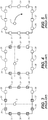
- the mesh may be an improved version of the conventional mesh shown in Fig. 7 .
- the mesh of Fig. 7 organizes seven speakers at the vertices of triangular faces T1, T2, T4, T5, and T6.
- the top edge of Fig. 7 corresponds to the front of the room which contains the seven speakers
- the bottom edge corresponds to the back of the room
- the assumed listener position is the center of Fig. 7 (the center of the room).
- the pan may be unstable if the speakers are assumed to be organized in accordance with the Fig. 7 mesh.
- the conventionally determined mesh of Fig. 7 includes triangles T1 and T2, which do not have left-right symmetry.
- a source in triangle T2 would fire more speakers to the right of the sweetspot, while a source in triangle T1 would fire more speakers to the left.
- the same seven speakers which are organized by the Fig. 7 mesh are assumed to be organized in accordance with the mesh shown in Fig. 8 , rather than that of Fig. 7 .
- the speakers are organized at the vertices of triangular faces T4, T5, and T6, and planar quadrilateral face Q1.
- the top edge of Fig. 8 corresponds to the front of the room which contains the speakers, the bottom edge corresponds to the back of the room, and the assumed listener position is the center of Fig. 8 (the center of the room).
- a set of speakers which are not axis-aligned (and not symmetrically aligned with respect to the assumed position of the listener) are assumed to be organized in accordance with a mesh having at least one face which is non-triangular.
- a set of seven speakers which are not axis-aligned (and not symmetrically aligned with respect to the assumed position of the listener) are assumed to be organized in accordance with the mesh shown in Fig. 8A .
- the speakers are organized at the vertices of triangular faces T40, T50, and T60, and planar quadrilateral face Q10.
- the top edge of Fig. 8A need not correspond to the front of the room which contains the speakers, and the bottom edge need not correspond to the back of the room.
- the mesh structure of the array of speakers is computed by triangulation of the speaker positions (or their convex hull) to determine an initial mesh whose faces are triangles (with the speaker positions coinciding with the triangle vertices), followed by replacement of at least one (e.g., more than one) of the triangular faces of the initial mesh by non-triangular, convex (and typically, planar) N-gons (e.g., quadrilaterals) with the speaker positions coinciding with the vertices of the N-gons. Faces of the initial mesh which are elongated triangles are not well suited to typical panning, and may be collapsed into quadrilaterals by removing edges shared with their neighbors from the initial mesh, resulting in a more uniform panning region.
- such an initial triangulation of the positions of speakers 10, 11, 12, 13, 15, 16, and 17 may determine the initial mesh shown in Fig. 2 .
- the faces of this initial mesh consist of triangles, with the speaker positions coinciding with the vertices of the triangles.
- the initial mesh may be modified in accordance with one exemplary embodiment of the invention, to replace the triangular face having vertices 12, 15, and 16, and the triangular face having vertices 12, 15, and 17, by a planar, convex quadrilateral.
- the initial mesh may be modified to determine the inventive mesh of Fig.
- FIG. 6 which includes the planar, convex quadrilateral having vertices 12, 15, 16, and 17 in place of the two noted triangular faces (having vertices 12, 15, and 16, and vertices 12, 15, and 17) of Fig. 2 .
- the pan will be more stable if the speakers are assumed to be organized in accordance with the Fig. 6 mesh, than if they are assumed to be organized in accordance with the conventional mesh of Fig. 2 .
- FIG. 9 For another example, consider the conventional triangular mesh of speakers shown in FIG. 9 .
- the mesh of Fig. 9 organizes nine speakers at the vertices of triangular faces T7, T8, T9, T10, T11, T12, T13, T14, and T5.
- the top edge of Fig. 9 corresponds to the front of the room which contains the nine speakers
- the bottom edge corresponds to the back of the room
- the assumed listener position is the center of Fig. 9 (the center of the room).
- some pans e.g., a pan from the location of front center speaker 60 to location 61 along the room's back wall
- the pan may be unstable if the speakers are assumed to be organized in accordance with the Fig. 9 mesh.
- the Fig. 9 the Fig.
- the mesh of Fig. 10 organizes the same nine speakers (which are organized by the Fig. 9 mesh) at the vertices of triangular faces T9, T12, and T14 (the same faces are those identically numbered in Fig. 9 ) and planar quadrilateral faces Q2, Q3, and Q4.
- some embodiments of the invention determine the mesh structure of the array of speakers as follows.
- An initial mesh structure of the array of speakers is computed by triangulation of the speaker positions (or their convex hull).
- the faces of the initial mesh e.g., the mesh of Fig. 2
- a modified mesh e.g., the mesh of Fig.
- N-gons e.g., quadrilaterals
- speaker positions For example, triangular faces (of the initial mesh) that cover the left side and right side of the panning area/volume in a non-uniform manner may be merged into quadrilateral faces (or faces which are other non-triangular N-gons) that cover the left and right sides of the panning area/volume more uniformly.
- an array of speakers is assumed to be organized as a mesh whose vertices coincide with the speaker locations (during rendering of an audio program including by determining, for each source location, an intersecting face of the mesh which includes the projection of the source location on the mesh), but the structure of the mesh is not determined by modification of an initial mesh.
- the mesh is an initial mesh which includes at least one face which is a non-triangular, convex (and typically, planar) N-gon (e.g., a quadrilateral), with the vertices of the N-gon coinciding with speaker locations.
- the contributing N-gon at any instant during the pan is determined (e.g., by testing) to be the polygon of the mesh which satisfies the following criterion: a ray connecting an assumed listener position (e.g., sweetspot) to the target source position (at the instant) intersects the contributing N-gon or a region enclosed by the contributing N-gon.
- a ray connecting an assumed listener position e.g., sweetspot
- the speakers may be assumed to be organized as the mesh of Fig. 6 .
- the face of the mesh which includes the projection (e.g., location "S3" in Fig. 6 ) of the source location on the mesh (e.g., the face intersected by the ray from listener location L to the source location S2) may be determined to be the contributing N-gon.
- the gains to be applied to the speaker feeds for the speakers at the vertices of this face may be determined to cause the sound emitted from these speakers to be perceived as emitting from the source location.
- the face of the mesh which includes the projection e.g., location "S5" in Fig.
- the gains to be applied to the speaker feeds for the speakers at the vertices of this face may be determined to cause the sound emitted from these speakers to be perceived as emitting from the source location.
- a gain is typically determined by computing the generalized barycentric coordinates with respect to the contributing N-gon of the target source point (i.e., of the intersection point of a ray, from the listener position to the target source point, and the contributing N-gon or a point within the contributing N-gon.
- the barycentric coordinates, b i (where i is an index in the range 1 ⁇ i ⁇ N), or their powers (e.g., b i 2 ), or renormalized versions thereof (to preserve power or amplitude), can be used as panning gains.
- an object channel of an object based audio program to be rendered
- N speaker feeds can be generated (for rendering audio which is perceived as emitting from the target source point) from the sequence of audio samples.
- Each of the N speaker feeds may be generated by a process including application of a different one of the panning gains (e.g., a different one of the barycentric coordinates or a scaled version thereof) to the sequence of audio samples.
- the contributing N-gon is a non-planar N-gon (e.g., a quadrilateral which is substantially planar but not exactly planar)
- a gain for each vertex of the contributing N-gon is similarly determined, e.g., by a variation on a conventional method of computing generalized barycentric coordinates, or by splitting the non-planar N-gon into planar N-gons or fitting a planar N-gon to it and then determining generalized barycentric coordinates for the planar N-gon(s).
- the computation that determines each contributing N-gon would be robust to minor floating-point/arithmetic errors that would cause a contributing N-gon to be not exactly planar.
- FIG. 11 is a diagram of an array of speakers including a layer of axis-aligned speakers 100, 101, 102, 103, 104, 105, and 106 (positioned on the floor of a room), and speakers 110, 111, 112, 113, 114, and 115 (which are positioned, as another layer of speakers, on the ceiling of the room and are not axis-aligned).
- speakers 110-115 are organized as a convex, 3D mesh of speakers whose faces include triangular faces T20 and T21, quadrilateral face Q10, and other faces (not shown in Fig. 11 ).
- the speakers may be assumed to be organized as the mesh of Fig. 11 .
- the face of each layer of the mesh which includes the projection of the source location on said layer of the mesh may be determined to be the contributing N-gon.
- the gains to be applied to the speaker feeds for the speakers at the vertices of each such face e.g., speakers 110, 111, and 112 of Fig. 11 if the contributing face is T20, or speakers 112, 113, 114, and 115 of Fig. 11 if the contributing face is Q10) may be determined to cause the sound emitted from these speakers to be perceived as emitting from the source location.
- the speakers may be assumed to be organized as the mesh of Fig. 11 .
- a dual-balance panning method of the type described above with reference to Figs. 2 , 3, and 4 may be employed to render a pan of a sound source in the plane of speakers 100, 101, 102, 103, 104, 105, and 106.
- 11 mesh which includes the projection of the source location on the mesh may be determined to be the contributing N-gon.
- the gains to be applied to the speaker feeds for the speakers at the vertices of this face e.g., speakers 110, 111, and 112 of Fig. 11 if the contributing face is T20, or speakers 112, 113, 114, and 115 of Fig. 11 if the contributing face is Q10) may be determined to cause the sound emitted from these speakers to be perceived as emitting from the source location.
- the rendering system could first pan through subsets of ceiling speakers 110, 111, 112, 113, 114, and 115 in the manner described in the previous paragraph (i.e., to render sound using a sequence of subsets of only the ceiling speakers 110-115) until an inflection point (a specific distance away from speaker 101 toward the line between speakers 104 and 105) is reached. Then, panning steps (e.g., a variation on a method described above with reference to Figs.
- 3-5 could be performed to determine a sequence of gains which in turn determine a sequence of blends of subsets of ceiling speakers 110-115 and subsets of lower speakers 100-106, to continue the pan (so that the source is perceived as dipping downward as it moves to the line on the floor which connects speakers 104 and 105).
- the invention is a method for rendering an audio program indicative of at least one source, including by generating speaker feeds for causing an array of loudspeakers to pan the source along a trajectory comprising a sequence of source locations, said method including steps of:
- step (a) includes steps of: determining an initial mesh whose faces are triangular faces, wherein the positions of the vertices of the triangular faces correspond to the locations of the loudspeakers; and replacing at least two of the triangular faces of the initial mesh by at least one replacement face which is a non-triangular, convex N-gon, thereby generating the 3D mesh.
- the gains determined in step (b) for said each subset of the loudspeakers (whose locations correspond to positions of the vertices of a vertex subset in the sequence of vertex subsets) are generalized barycentric coordinates of one of the source locations, with respect to the vertices of the corresponding vertex subset.
- the inventive system is or includes a general or special purpose processor (e.g., an implementation of processing subsystem 501 of Fig. 12 ) programmed with software (or firmware) and/or otherwise configured to perform an embodiment of the inventive method.
- the inventive system is implemented by appropriately configuring (e.g., by programming) a configurable audio digital signal processor (DSP) to perform an embodiment of the inventive method.
- the audio DSP can be a conventional audio DSP that is configurable (e.g., programmable by appropriate software or firmware, or otherwise configurable in response to control data) to perform any of a variety of operations on input audio data.
- the inventive system is or includes a general purpose processor, coupled to receive input audio data (indicative of an audio program) and coupled to receive (or configured to store) speaker array data indicative of the positions of speakers of a speaker array, and programmed to generate output data indicative of gain values and/or speaker feeds in response to the input audio data and the speaker array data by performing an embodiment of the inventive method.
- the processor is typically programmed with software (or firmware) and/or otherwise configured (e.g., in response to control data) to perform any of a variety of operations on the input data, including an embodiment of the inventive method.
- the system of FIG. 12 is an example of such a system.
- processing subsystem 501 which in one implementation is a general purpose processor
- the input audio data is indicative of an audio program.
- the audio program is an object based audio program comprising a set of one or more object channels (and optionally also at least one speaker channel), each comprising audio samples, and metadata indicative of at least one trajectory of at least one audio object (source) which emits sound indicated by audio samples of at least one object channel.
- the system of Fig. 12 also includes input device 503 (e.g., a mouse and/or a keyboard) coupled to processing subsystem 501 (sometimes referred to as processor 501), storage medium 504 coupled to processor 501, display device 505 coupled to processor 501, speaker feed generation subsystem 506 (labeled "rendering system” in Fig. 12 ) coupled to processor 501, and speakers 507.
- Subsystem 506 is configured to generate, in response to the input audio and a sequence of gain values generated by processor 501 in response to the input audio, speaker feeds for driving speakers 507 (e.g., to emit sound indicative of a pan of at least one source indicated by the input audio) or data indicative of such speaker feeds.
- Subsystem 506 may be configured to generate each of the N speaker feeds (for each source position) by a process including application of a different one of N gains determined by processor 501 for the N-gon face of the mesh which corresponds to the source position (i.e., the face intersected by a ray from the assumed listener position to the source position), to the sequence of audio samples for the source position.
- the N gains (a set of N gain values) determined by processor 501 for each source position may be the barycentric coordinates (or a scaled version of the barycentric coordinates) of the source position relative to the vertices of the N-gon face of the mesh which corresponds to the source position.
- Processor 501 is programmed generate gain values (for assertion to subsystem 506) for enabling subsystem 506 to generate the speaker feeds for driving speakers 507, with the assumption that speakers 507 are organized as a mesh of convex (and typically, planar) N-gons.
- Processor 501 is programmed to determine (in accordance with an embodiment of the inventive method) the mesh of convex N-gons, in response to data indicative of the positions of speakers 507 and data indicative of an assumed position of a listener (relative to the positions of speakers 507).
- Processor 501 is programmed to implement the inventive method in response to instructions and data (e.g., data indicative of the positions of speakers 507) entered by user manipulation of input device 503, and/or instructions and data otherwise provided to processor 501.
- processing subsystem 501 and/or subsystem 506 of the Fig. 12 system is an audio digital signal processor (DSP) which is operable to generate gain values for generating speaker feeds, and/or data indicative of speaker feeds, and/or speaker feeds, in response to input audio (and data indicative of the positions of speakers 507.
- DSP audio digital signal processor
- Computer readable storage medium 504 (e.g., an optical disk or other tangible object) has computer code stored thereon that is suitable for programming processor 501 to perform an embodiment of the inventive method.
- processor 501 executes the computer code to process data indicative of input audio (and data indicative of the positions of speakers 507) in accordance with the invention to generate output data indicative of gains to be employed by subsystem 506 to generate speaker feeds for driving speakers 507 to image at least one sound source (indicated by the input audio), e.g., as the source pans along a trajectory indicated by metadata including in the input audio.
- aspects of the invention are a computer system programmed to perform any embodiment of the inventive method, and a computer readable medium which stores computer-readable code for implementing any embodiment of the inventive method.
Landscapes
- Physics & Mathematics (AREA)
- Engineering & Computer Science (AREA)
- Acoustics & Sound (AREA)
- Signal Processing (AREA)
- Stereophonic System (AREA)
- Circuit For Audible Band Transducer (AREA)
- Obtaining Desirable Characteristics In Audible-Bandwidth Transducers (AREA)
Claims (11)
- Verfahren zum Rendern eines Audioprogramms, das mindestens eine Quelle anzeigt, einschließlich durch Erzeugen von Lautsprecher-Feeds, um eine Anordnung von Lautsprechern (110-115) dazu zu bringen, die Quelle entlang einer Bahn zu schwenken, die eine Abfolge von Quellenstandorten umfasst, wobei das Verfahren die Schritte einschließt des:
Bestimmens eines ursprünglichen Netzes unter Verwendung von Triangulation von Standorten der Lautsprecher der Lautsprecheranordnung (110-115); wobei Flächen des ursprünglichen Netzes dreieckige Flächen sind, wobei die Positionen der Scheitelpunkte der dreieckigen Flächen (T20, T21) den Standorten der Lautsprecher entsprechen;(a) Bestimmens eines Netzes, dessen Flächen, F i , konvexe N-Ecke sind, wobei Positionen der Scheitelpunkte der N-Ecke Standorten der Lautsprecher entsprechen, i ein Index im Bereich 1 ≤ i ≤ M ist, M eine ganze Zahl größer als 2 ist, jede der Flächen, F i , ein konvexes Vieleck ist, das N i Kanten aufweist, N i eine beliebige ganze Zahl größer als 2 ist, und N i bei mindestens einer der Flächen größer als 3 ist; wobei das Bestimmen des Netzes das Ersetzen von mindestens zwei der dreieckigen Flächen (T20, T21) des ursprünglichen Netzes durch mindestens eine Ersatzfläche umfasst, die ein nicht dreieckiges, konvexes N-Eck ist, wodurch das Netz erzeugt wird; wobei das Ersetzen das Entfernen von Kanten umfasst, die die mindestens zwei der dreieckigen Flächen (T20, T21) sich teilen, und wobei die mindestens zwei der dreieckigen Flächen (T20, T21) eine dreieckige Fläche, die einen Winkel von kleiner als einem vorbestimmten Schwellenwinkel aufweist, und eine an dieselbe angrenzende dreieckige Fläche einschließen, und/oder eine dreieckige Fläche, die sich zu sowohl der linken als auch rechten Seite einer angenommenen Hörerposition erstreckt und bei der sich ein erster Teil ihres Flächeninhalts, der sich zur Linken des angenommenen Hörerstandorts befindet, wesentlich von einem zweiten Teil ihres Flächeninhalts unterscheidet, der sich zur Rechten des angenommenen Hörerstandorts befindet, und eine an dieselbe angrenzende dreieckige Fläche einschließen;(b) Bestimmens einer Abfolge von Projektionen der Quellenstandorte auf einer Abfolge von Flächen des Netzes, und Bestimmens eines Satzes von Verstärkungen für jeden Teilsatz der Lautsprecher, deren Standorte Positionen von Scheitelpunkten jeder Fläche des Netzes in der Abfolge von Flächen entsprechen; und
Erzeugens von Lautsprecher-Feeds für jeden Teilsatz der Lautsprecher, einschließlich durch Anwenden der in Schritt (b) für den Teilsatz der Lautsprecher bestimmten Verstärkungen auf Audioabtastungen des Audioprogramms. - Verfahren nach Anspruch 1, wobei die Flächen des Netzes mindestens eine dreieckige Fläche und mindestens eine vierseitige Fläche (Q10) einschließen.
- Verfahren nach Anspruch 1, wobei die Flächen des Netzes mindestens eine dreieckige Fläche und mindestens eine planare, vierseitige Fläche einschließen.
- Verfahren nach Anspruch 1, wobei jede der Flächen des Netzes ein konvexes, planares Vieleck ist, und Schritt (b) einen Schritt einschließt des:
Bestimmens von generalisierten baryzentrischen Koordinaten für jede Projektion des Quellenstandorts in Bezug auf Scheitelpunkte der Fläche für den Quellenstandort. - Verfahren nach Anspruch 4, wobei die in Schritt (b) für jeden Teilsatz der Lautsprecher bestimmten Verstärkungen die generalisierten baryzentrischen Koordinaten der Projektion des Quellenstandorts in Bezug auf die Scheitelpunkte der Fläche sind, die dem Teilsatz der Lautsprecher entspricht.
- System zum Rendern eines Audioprogramms, das mindestens eine Quelle und eine Bahn für die Quelle anzeigt, einschließlich durch Erzeugen von Lautsprecher-Feeds, um die Quelle unter Verwendung einer Anordnung von Lautsprechern (110-115) entlang der Bahn zu schwenken, wobei die Bahn eine Abfolge von Quellenstandorten umfasst, wobei das System einschließt:ein Verarbeitungs-Teilsystem (501), das dazu konfiguriert istein ursprüngliches Netz unter Verwendung von Triangulation von Standorten der Lautsprecher der Lautsprecheranordnung (110-115) zu bestimmen; wobei Flächen des ursprünglichen Netzes dreieckige Flächen (T20, T21) sind, wobei die Positionen der Scheitelpunkte der dreieckigen Flächen (T20, T21) den Standorten der Lautsprecher entsprechen; undein Netz zu bestimmen, dessen Flächen, F i , konvexe N-Ecke sind, wobei Positionen der Scheitelpunkte der N-Ecke Standorten der Lautsprecher entsprechen, i ein Index im Bereich 1 ≤ i ≤ M ist, M eine ganze Zahl größer als 2 ist, jede der Flächen, F i , ein konvexes Vieleck ist, das N i Kanten aufweist, N i eine beliebige ganze Zahl größer als 2 ist, und N i bei mindestens einer der Flächen größer als 3 ist, wobei das Bestimmen des Netzes das Ersetzen von mindestens zwei der dreieckigen Flächen (T20, T21) des ursprünglichen Netzes durch mindestens eine Ersatzfläche umfasst, die ein nicht dreieckiges, konvexes N-Eck ist, wodurch das Netz erzeugt wird; wobei das Ersetzen das Entfernen von Kanten umfasst, die die mindestens zwei der dreieckigen Flächen (T20, T21) sich teilen, und wobei die mindestens zwei der dreieckigen Flächen (T20, T21) eine dreieckige Fläche, die einen Winkel von kleiner als einem vorbestimmten Schwellenwinkel aufweist, und eine an dieselbe angrenzende dreieckige Fläche einschließen, und/oder eine dreieckige Fläche, die sich zu sowohl der linken als auch rechten Seite einer angenommenen Hörerposition erstreckt und bei der sich ein erster Teil ihres Flächeninhalts, der sich zur Linken des angenommenen Hörerstandorts befindet, wesentlich von einem zweiten Teil ihres Flächeninhalts unterscheidet, der sich zur Rechten des angenommenen Hörerstandorts befindet, und eine an dieselbe angrenzende dreieckige Fläche einschließen; wobei das Verarbeitungs-Teilsystem so gekoppelt ist, dass es Daten empfängt, die das Audioprogramm anzeigen, und dazu konfiguriert ist, in Antwort auf die Daten, die das Audioprogramm anzeigen, eine Abfolge von Projektionen der Quellenstandorte auf einer Abfolge von Flächen des Netzes zu bestimmen, und einen Satz von Verstärkungswerten für jeden Teilsatz der Lautsprecher zu bestimmen, deren Standorte Positionen von Scheitelpunkten jeder Fläche des Netzes in der Abfolge von Flächen entsprechen; undein Lautsprecher-Feed-Erzeugungs-Teilsystem (506), das so gekoppelt und konfiguriert ist, dass es in Antwort auf die Daten, die das Audioprogramm anzeigen, und die Verstärkungswerte die Lautsprecher-Feeds erzeugt.
- System nach Anspruch 6, wobei die Flächen des Netzes mindestens eine dreieckige Fläche und mindestens eine vierseitige Fläche (Q10) einschließen.
- System nach Anspruch 6, wobei die Flächen des Netzes mindestens eine dreieckige Fläche und mindestens eine planare, vierseitige Fläche einschließen.
- System nach Anspruch 6,
wobei mindestens das Verarbeitungs-Teilsystem (501) als ein digitaler Audiosignalprozessor implementiert ist; oder
wobei das Verarbeitungs-Teilsystem (501) ein Allzweckprozessor ist, der so programmiert wurde, dass er in Antwort auf die Daten, die das Audioprogramm anzeigen, die Verstärkungswerte erzeugt. - System nach Anspruch 6, wobei jede der Flächen des Netzes ein konvexes, planares Vieleck ist, und das Verarbeitungs-Teilsystem (501) dazu konfiguriert ist, generalisierte baryzentrische Koordinaten jeder Projektion des Quellenstandorts in Bezug auf Scheitelpunkte der Fläche für den Quellenstandort zu bestimmen.
- System nach Anspruch 10, wobei die Verstärkungswerte für jeden Teilsatz der Lautsprecher die generalisierten baryzentrischen Koordinaten der Projektion des Quellenstandorts in Bezug auf die Scheitelpunkte der Fläche sind, die dem Teilsatz der Lautsprecher entspricht.
Applications Claiming Priority (2)
| Application Number | Priority Date | Filing Date | Title |
|---|---|---|---|
| US201361805977P | 2013-03-28 | 2013-03-28 | |
| PCT/US2014/031239 WO2014160576A2 (en) | 2013-03-28 | 2014-03-19 | Rendering audio using speakers organized as a mesh of arbitrary n-gons |
Publications (2)
| Publication Number | Publication Date |
|---|---|
| EP2979467A2 EP2979467A2 (de) | 2016-02-03 |
| EP2979467B1 true EP2979467B1 (de) | 2019-12-18 |
Family
ID=50442752
Family Applications (1)
| Application Number | Title | Priority Date | Filing Date |
|---|---|---|---|
| EP14716208.5A Active EP2979467B1 (de) | 2013-03-28 | 2014-03-19 | Audiowiedergabe anhand von lautsprechern in einer anordnung als gitter aus beliebigen n-gons |
Country Status (5)
| Country | Link |
|---|---|
| US (1) | US9756444B2 (de) |
| EP (1) | EP2979467B1 (de) |
| JP (1) | JP6082160B2 (de) |
| CN (1) | CN105103569B (de) |
| WO (1) | WO2014160576A2 (de) |
Families Citing this family (23)
| Publication number | Priority date | Publication date | Assignee | Title |
|---|---|---|---|---|
| KR102414609B1 (ko) | 2013-04-26 | 2022-06-30 | 소니그룹주식회사 | 음성 처리 장치, 정보 처리 방법, 및 기록 매체 |
| US9338573B2 (en) | 2013-07-30 | 2016-05-10 | Dts, Inc. | Matrix decoder with constant-power pairwise panning |
| ES2772851T3 (es) | 2013-11-27 | 2020-07-08 | Dts Inc | Mezcla de matriz basada en multipletes para audio de múltiples canales de alta cantidad de canales |
| EP3143779B1 (de) * | 2014-05-13 | 2020-10-07 | Fraunhofer Gesellschaft zur Förderung der Angewand | Verfahren und vorrichtung für edge-fading-amplitude-panning |
| KR20160122029A (ko) * | 2015-04-13 | 2016-10-21 | 삼성전자주식회사 | 스피커 정보에 기초하여, 오디오 신호를 처리하는 방법 및 장치 |
| WO2016172111A1 (en) * | 2015-04-20 | 2016-10-27 | Dolby Laboratories Licensing Corporation | Processing audio data to compensate for partial hearing loss or an adverse hearing environment |
| RU2019138260A (ru) | 2015-06-24 | 2019-12-05 | Сони Корпорейшн | Устройство, способ и программа аудиообработки |
| HK1221372A2 (zh) * | 2016-03-29 | 2017-05-26 | 万维数码有限公司 | 一种获得空间音频定向向量的方法、装置及设备 |
| EP3529999A4 (de) * | 2016-11-17 | 2019-11-13 | Samsung Electronics Co., Ltd. | System und verfahren zur erzeugung von audiodaten für eine kopfmontierte anzeigevorrichtung |
| US11012803B2 (en) | 2017-01-27 | 2021-05-18 | Auro Technologies Nv | Processing method and system for panning audio objects |
| EP3662470B1 (de) * | 2017-08-01 | 2021-03-24 | Dolby Laboratories Licensing Corporation | Audio-objektklassifizierung basierend auf positionsmetadaten |
| US11297424B2 (en) * | 2017-10-10 | 2022-04-05 | Google Llc | Joint wideband source localization and acquisition based on a grid-shift approach |
| CN107948880A (zh) * | 2017-11-10 | 2018-04-20 | 佛山市天啊科技有限公司 | 一种应用于汽车的车载快装音响系统 |
| WO2019149337A1 (en) * | 2018-01-30 | 2019-08-08 | Fraunhofer-Gesellschaft zur Förderung der angewandten Forschung e.V. | Apparatuses for converting an object position of an audio object, audio stream provider, audio content production system, audio playback apparatus, methods and computer programs |
| ES2913426T3 (es) * | 2018-03-13 | 2022-06-02 | Nokia Technologies Oy | Reproducción de sonido espacial usando sistemas de altavoz de múltiples canales |
| JP7294328B2 (ja) * | 2018-04-24 | 2023-06-20 | ソニーグループ株式会社 | 表示制御装置、表示制御方法及びプログラム |
| US11356791B2 (en) * | 2018-12-27 | 2022-06-07 | Gilberto Torres Ayala | Vector audio panning and playback system |
| US20220232338A1 (en) * | 2019-06-05 | 2022-07-21 | Sony Group Corporation | Information processing apparatus, information processing method, and program |
| US20230326469A1 (en) * | 2020-08-27 | 2023-10-12 | Dolby Laboratories Licensing Corporation | Matrix coded stereo signal with periphonic elements |
| GB2599359A (en) * | 2020-09-23 | 2022-04-06 | Nokia Technologies Oy | Spatial audio rendering |
| CN112153538B (zh) * | 2020-09-24 | 2022-02-22 | 京东方科技集团股份有限公司 | 显示装置及其全景声实现方法、非易失性存储介质 |
| WO2022179701A1 (en) * | 2021-02-26 | 2022-09-01 | Fraunhofer-Gesellschaft zur Förderung der angewandten Forschung e.V. | Apparatus and method for rendering audio objects |
| CN118830266A (zh) * | 2022-01-04 | 2024-10-22 | 弗劳恩霍夫应用研究促进协会 | 用于实现多功能音频对象渲染的设备和方法 |
Family Cites Families (24)
| Publication number | Priority date | Publication date | Assignee | Title |
|---|---|---|---|---|
| JPH08272380A (ja) | 1995-03-30 | 1996-10-18 | Taimuuea:Kk | 仮想3次元空間音響の再生方法および装置 |
| US6072878A (en) | 1997-09-24 | 2000-06-06 | Sonic Solutions | Multi-channel surround sound mastering and reproduction techniques that preserve spatial harmonics |
| AU2002240800A1 (en) | 2001-01-29 | 2002-08-12 | Siemens Aktiengesellschaft | Electroacoustic conversion of audio signals, especially voice signals |
| US7061483B2 (en) | 2001-02-08 | 2006-06-13 | California Institute Of Technology | Methods for computing barycentric coordinates generalized to irregular n-gons and applications of the same |
| KR100522593B1 (ko) | 2002-07-08 | 2005-10-19 | 삼성전자주식회사 | 다채널 입체음향 사운드 생성방법 및 장치 |
| FI118247B (fi) | 2003-02-26 | 2007-08-31 | Fraunhofer Ges Forschung | Menetelmä luonnollisen tai modifioidun tilavaikutelman aikaansaamiseksi monikanavakuuntelussa |
| JP2004266453A (ja) | 2003-02-28 | 2004-09-24 | Toshiba Corp | ネットワークシステム、サーバ機器および通信方法 |
| KR100608002B1 (ko) | 2004-08-26 | 2006-08-02 | 삼성전자주식회사 | 가상 음향 재생 방법 및 그 장치 |
| US20060247918A1 (en) | 2005-04-29 | 2006-11-02 | Microsoft Corporation | Systems and methods for 3D audio programming and processing |
| US8688249B2 (en) * | 2006-04-19 | 2014-04-01 | Sonita Logic Limted | Processing audio input signals |
| US8483395B2 (en) | 2007-05-04 | 2013-07-09 | Electronics And Telecommunications Research Institute | Sound field reproduction apparatus and method for reproducing reflections |
| JP4530007B2 (ja) | 2007-08-02 | 2010-08-25 | ヤマハ株式会社 | 音場制御装置 |
| US8391500B2 (en) | 2008-10-17 | 2013-03-05 | University Of Kentucky Research Foundation | Method and system for creating three-dimensional spatial audio |
| KR101517592B1 (ko) * | 2008-11-11 | 2015-05-04 | 삼성전자 주식회사 | 고분해능을 가진 화면음원 위치장치 및 재생방법 |
| EP2205007B1 (de) | 2008-12-30 | 2019-01-09 | Dolby International AB | Verfahren und Vorrichtung zur Kodierung dreidimensionaler Hörbereiche und zur optimalen Rekonstruktion |
| JP2010252220A (ja) | 2009-04-20 | 2010-11-04 | Nippon Hoso Kyokai <Nhk> | 3次元音響パンニング装置およびそのプログラム |
| JP5439602B2 (ja) | 2009-11-04 | 2014-03-12 | フラウンホーファー−ゲゼルシャフト・ツール・フェルデルング・デル・アンゲヴァンテン・フォルシュング・アインゲトラーゲネル・フェライン | 仮想音源に関連するオーディオ信号についてスピーカ設備のスピーカの駆動係数を計算する装置および方法 |
| KR102294460B1 (ko) | 2010-03-26 | 2021-08-27 | 돌비 인터네셔널 에이비 | 오디오 재생을 위한 오디오 사운드필드 표현을 디코딩하는 방법 및 장치 |
| US9015612B2 (en) | 2010-11-09 | 2015-04-21 | Sony Corporation | Virtual room form maker |
| JP5867672B2 (ja) | 2011-03-30 | 2016-02-24 | ヤマハ株式会社 | 音像定位制御装置 |
| US9094771B2 (en) | 2011-04-18 | 2015-07-28 | Dolby Laboratories Licensing Corporation | Method and system for upmixing audio to generate 3D audio |
| WO2012164444A1 (en) | 2011-06-01 | 2012-12-06 | Koninklijke Philips Electronics N.V. | An audio system and method of operating therefor |
| PL2727381T3 (pl) | 2011-07-01 | 2022-05-02 | Dolby Laboratories Licensing Corporation | Sposób i urządzenie do renderowania obiektów audio |
| WO2013181272A2 (en) * | 2012-05-31 | 2013-12-05 | Dts Llc | Object-based audio system using vector base amplitude panning |
-
2014
- 2014-03-19 EP EP14716208.5A patent/EP2979467B1/de active Active
- 2014-03-19 WO PCT/US2014/031239 patent/WO2014160576A2/en not_active Ceased
- 2014-03-19 CN CN201480018909.8A patent/CN105103569B/zh active Active
- 2014-03-19 JP JP2016505498A patent/JP6082160B2/ja active Active
- 2014-03-19 US US14/780,159 patent/US9756444B2/en active Active
Non-Patent Citations (1)
| Title |
|---|
| None * |
Also Published As
| Publication number | Publication date |
|---|---|
| CN105103569A (zh) | 2015-11-25 |
| US9756444B2 (en) | 2017-09-05 |
| WO2014160576A3 (en) | 2014-12-11 |
| CN105103569B (zh) | 2017-05-24 |
| EP2979467A2 (de) | 2016-02-03 |
| JP2016518049A (ja) | 2016-06-20 |
| JP6082160B2 (ja) | 2017-02-15 |
| WO2014160576A2 (en) | 2014-10-02 |
| US20160044433A1 (en) | 2016-02-11 |
Similar Documents
| Publication | Publication Date | Title |
|---|---|---|
| EP2979467B1 (de) | Audiowiedergabe anhand von lautsprechern in einer anordnung als gitter aus beliebigen n-gons | |
| JP5740531B2 (ja) | オブジェクトベースオーディオのアップミキシング | |
| JP6055576B2 (ja) | 任意のスピーカー・レイアウトへのオーディオ・オブジェクトのパン | |
| CN105431900B (zh) | 用于处理音频数据的方法和装置、介质及设备 | |
| CN105264914B (zh) | 音频再生装置以及方法 | |
| EP3069528B1 (de) | Schirmrelative darstellung von audio sowie codierung und decodierung von audio für solch eine darstellung | |
| EP2741523B1 (de) | Objektbasierte Audiowiedergabe mit visuelle Verfolgung von mindestens einem Zuhörer | |
| CN115486097A (zh) | 基于格栅路径寻找的衍射建模 | |
| JP2018509864A (ja) | ヘッドフォン仮想化のための残響生成 | |
| CN1906971A (zh) | 产生低频声道的设备与方法 | |
| US11302339B2 (en) | Spatial sound reproduction using multichannel loudspeaker systems | |
| RU2803638C2 (ru) | Обработка пространственно диффузных или больших звуковых объектов | |
| HK40074946B (en) | Headphone virtualization | |
| HK40017396A (en) | Processing spatially diffuse or large audio objects | |
| HK40017396B (en) | Processing spatially diffuse or large audio objects | |
| HK1195838B (en) | Upmixing object based audio | |
| HK1195838A (en) | Upmixing object based audio |
Legal Events
| Date | Code | Title | Description |
|---|---|---|---|
| PUAI | Public reference made under article 153(3) epc to a published international application that has entered the european phase |
Free format text: ORIGINAL CODE: 0009012 |
|
| 17P | Request for examination filed |
Effective date: 20151028 |
|
| AK | Designated contracting states |
Kind code of ref document: A2 Designated state(s): AL AT BE BG CH CY CZ DE DK EE ES FI FR GB GR HR HU IE IS IT LI LT LU LV MC MK MT NL NO PL PT RO RS SE SI SK SM TR |
|
| AX | Request for extension of the european patent |
Extension state: BA ME |
|
| DAX | Request for extension of the european patent (deleted) | ||
| RAP1 | Party data changed (applicant data changed or rights of an application transferred) |
Owner name: DOLBY LABORATORIES LICENSING CORPORATION |
|
| STAA | Information on the status of an ep patent application or granted ep patent |
Free format text: STATUS: EXAMINATION IS IN PROGRESS |
|
| 17Q | First examination report despatched |
Effective date: 20181220 |
|
| GRAP | Despatch of communication of intention to grant a patent |
Free format text: ORIGINAL CODE: EPIDOSNIGR1 |
|
| STAA | Information on the status of an ep patent application or granted ep patent |
Free format text: STATUS: GRANT OF PATENT IS INTENDED |
|
| GRAS | Grant fee paid |
Free format text: ORIGINAL CODE: EPIDOSNIGR3 |
|
| INTG | Intention to grant announced |
Effective date: 20191014 |
|
| GRAA | (expected) grant |
Free format text: ORIGINAL CODE: 0009210 |
|
| STAA | Information on the status of an ep patent application or granted ep patent |
Free format text: STATUS: THE PATENT HAS BEEN GRANTED |
|
| AK | Designated contracting states |
Kind code of ref document: B1 Designated state(s): AL AT BE BG CH CY CZ DE DK EE ES FI FR GB GR HR HU IE IS IT LI LT LU LV MC MK MT NL NO PL PT RO RS SE SI SK SM TR |
|
| REG | Reference to a national code |
Ref country code: CH Ref legal event code: EP |
|
| REG | Reference to a national code |
Ref country code: DE Ref legal event code: R096 Ref document number: 602014058529 Country of ref document: DE |
|
| REG | Reference to a national code |
Ref country code: IE Ref legal event code: FG4D |
|
| REG | Reference to a national code |
Ref country code: AT Ref legal event code: REF Ref document number: 1215924 Country of ref document: AT Kind code of ref document: T Effective date: 20200115 |
|
| REG | Reference to a national code |
Ref country code: NL Ref legal event code: MP Effective date: 20191218 |
|
| PG25 | Lapsed in a contracting state [announced via postgrant information from national office to epo] |
Ref country code: LV Free format text: LAPSE BECAUSE OF FAILURE TO SUBMIT A TRANSLATION OF THE DESCRIPTION OR TO PAY THE FEE WITHIN THE PRESCRIBED TIME-LIMIT Effective date: 20191218 Ref country code: SE Free format text: LAPSE BECAUSE OF FAILURE TO SUBMIT A TRANSLATION OF THE DESCRIPTION OR TO PAY THE FEE WITHIN THE PRESCRIBED TIME-LIMIT Effective date: 20191218 Ref country code: LT Free format text: LAPSE BECAUSE OF FAILURE TO SUBMIT A TRANSLATION OF THE DESCRIPTION OR TO PAY THE FEE WITHIN THE PRESCRIBED TIME-LIMIT Effective date: 20191218 Ref country code: GR Free format text: LAPSE BECAUSE OF FAILURE TO SUBMIT A TRANSLATION OF THE DESCRIPTION OR TO PAY THE FEE WITHIN THE PRESCRIBED TIME-LIMIT Effective date: 20200319 Ref country code: FI Free format text: LAPSE BECAUSE OF FAILURE TO SUBMIT A TRANSLATION OF THE DESCRIPTION OR TO PAY THE FEE WITHIN THE PRESCRIBED TIME-LIMIT Effective date: 20191218 Ref country code: BG Free format text: LAPSE BECAUSE OF FAILURE TO SUBMIT A TRANSLATION OF THE DESCRIPTION OR TO PAY THE FEE WITHIN THE PRESCRIBED TIME-LIMIT Effective date: 20200318 Ref country code: NO Free format text: LAPSE BECAUSE OF FAILURE TO SUBMIT A TRANSLATION OF THE DESCRIPTION OR TO PAY THE FEE WITHIN THE PRESCRIBED TIME-LIMIT Effective date: 20200318 |
|
| REG | Reference to a national code |
Ref country code: LT Ref legal event code: MG4D |
|
| PG25 | Lapsed in a contracting state [announced via postgrant information from national office to epo] |
Ref country code: RS Free format text: LAPSE BECAUSE OF FAILURE TO SUBMIT A TRANSLATION OF THE DESCRIPTION OR TO PAY THE FEE WITHIN THE PRESCRIBED TIME-LIMIT Effective date: 20191218 Ref country code: HR Free format text: LAPSE BECAUSE OF FAILURE TO SUBMIT A TRANSLATION OF THE DESCRIPTION OR TO PAY THE FEE WITHIN THE PRESCRIBED TIME-LIMIT Effective date: 20191218 |
|
| PG25 | Lapsed in a contracting state [announced via postgrant information from national office to epo] |
Ref country code: AL Free format text: LAPSE BECAUSE OF FAILURE TO SUBMIT A TRANSLATION OF THE DESCRIPTION OR TO PAY THE FEE WITHIN THE PRESCRIBED TIME-LIMIT Effective date: 20191218 |
|
| PG25 | Lapsed in a contracting state [announced via postgrant information from national office to epo] |
Ref country code: EE Free format text: LAPSE BECAUSE OF FAILURE TO SUBMIT A TRANSLATION OF THE DESCRIPTION OR TO PAY THE FEE WITHIN THE PRESCRIBED TIME-LIMIT Effective date: 20191218 Ref country code: RO Free format text: LAPSE BECAUSE OF FAILURE TO SUBMIT A TRANSLATION OF THE DESCRIPTION OR TO PAY THE FEE WITHIN THE PRESCRIBED TIME-LIMIT Effective date: 20191218 Ref country code: PT Free format text: LAPSE BECAUSE OF FAILURE TO SUBMIT A TRANSLATION OF THE DESCRIPTION OR TO PAY THE FEE WITHIN THE PRESCRIBED TIME-LIMIT Effective date: 20200513 Ref country code: NL Free format text: LAPSE BECAUSE OF FAILURE TO SUBMIT A TRANSLATION OF THE DESCRIPTION OR TO PAY THE FEE WITHIN THE PRESCRIBED TIME-LIMIT Effective date: 20191218 Ref country code: CZ Free format text: LAPSE BECAUSE OF FAILURE TO SUBMIT A TRANSLATION OF THE DESCRIPTION OR TO PAY THE FEE WITHIN THE PRESCRIBED TIME-LIMIT Effective date: 20191218 |
|
| PG25 | Lapsed in a contracting state [announced via postgrant information from national office to epo] |
Ref country code: SM Free format text: LAPSE BECAUSE OF FAILURE TO SUBMIT A TRANSLATION OF THE DESCRIPTION OR TO PAY THE FEE WITHIN THE PRESCRIBED TIME-LIMIT Effective date: 20191218 Ref country code: IS Free format text: LAPSE BECAUSE OF FAILURE TO SUBMIT A TRANSLATION OF THE DESCRIPTION OR TO PAY THE FEE WITHIN THE PRESCRIBED TIME-LIMIT Effective date: 20200418 Ref country code: SK Free format text: LAPSE BECAUSE OF FAILURE TO SUBMIT A TRANSLATION OF THE DESCRIPTION OR TO PAY THE FEE WITHIN THE PRESCRIBED TIME-LIMIT Effective date: 20191218 |
|
| REG | Reference to a national code |
Ref country code: DE Ref legal event code: R097 Ref document number: 602014058529 Country of ref document: DE |
|
| REG | Reference to a national code |
Ref country code: AT Ref legal event code: MK05 Ref document number: 1215924 Country of ref document: AT Kind code of ref document: T Effective date: 20191218 |
|
| PLBE | No opposition filed within time limit |
Free format text: ORIGINAL CODE: 0009261 |
|
| STAA | Information on the status of an ep patent application or granted ep patent |
Free format text: STATUS: NO OPPOSITION FILED WITHIN TIME LIMIT |
|
| PG25 | Lapsed in a contracting state [announced via postgrant information from national office to epo] |
Ref country code: ES Free format text: LAPSE BECAUSE OF FAILURE TO SUBMIT A TRANSLATION OF THE DESCRIPTION OR TO PAY THE FEE WITHIN THE PRESCRIBED TIME-LIMIT Effective date: 20191218 Ref country code: MC Free format text: LAPSE BECAUSE OF FAILURE TO SUBMIT A TRANSLATION OF THE DESCRIPTION OR TO PAY THE FEE WITHIN THE PRESCRIBED TIME-LIMIT Effective date: 20191218 Ref country code: DK Free format text: LAPSE BECAUSE OF FAILURE TO SUBMIT A TRANSLATION OF THE DESCRIPTION OR TO PAY THE FEE WITHIN THE PRESCRIBED TIME-LIMIT Effective date: 20191218 |
|
| REG | Reference to a national code |
Ref country code: CH Ref legal event code: PL |
|
| 26N | No opposition filed |
Effective date: 20200921 |
|
| PG25 | Lapsed in a contracting state [announced via postgrant information from national office to epo] |
Ref country code: SI Free format text: LAPSE BECAUSE OF FAILURE TO SUBMIT A TRANSLATION OF THE DESCRIPTION OR TO PAY THE FEE WITHIN THE PRESCRIBED TIME-LIMIT Effective date: 20191218 Ref country code: AT Free format text: LAPSE BECAUSE OF FAILURE TO SUBMIT A TRANSLATION OF THE DESCRIPTION OR TO PAY THE FEE WITHIN THE PRESCRIBED TIME-LIMIT Effective date: 20191218 |
|
| REG | Reference to a national code |
Ref country code: BE Ref legal event code: MM Effective date: 20200331 |
|
| PG25 | Lapsed in a contracting state [announced via postgrant information from national office to epo] |
Ref country code: LU Free format text: LAPSE BECAUSE OF NON-PAYMENT OF DUE FEES Effective date: 20200319 |
|
| PG25 | Lapsed in a contracting state [announced via postgrant information from national office to epo] |
Ref country code: LI Free format text: LAPSE BECAUSE OF NON-PAYMENT OF DUE FEES Effective date: 20200331 Ref country code: CH Free format text: LAPSE BECAUSE OF NON-PAYMENT OF DUE FEES Effective date: 20200331 Ref country code: IT Free format text: LAPSE BECAUSE OF FAILURE TO SUBMIT A TRANSLATION OF THE DESCRIPTION OR TO PAY THE FEE WITHIN THE PRESCRIBED TIME-LIMIT Effective date: 20191218 Ref country code: IE Free format text: LAPSE BECAUSE OF NON-PAYMENT OF DUE FEES Effective date: 20200319 |
|
| PG25 | Lapsed in a contracting state [announced via postgrant information from national office to epo] |
Ref country code: PL Free format text: LAPSE BECAUSE OF FAILURE TO SUBMIT A TRANSLATION OF THE DESCRIPTION OR TO PAY THE FEE WITHIN THE PRESCRIBED TIME-LIMIT Effective date: 20191218 Ref country code: BE Free format text: LAPSE BECAUSE OF NON-PAYMENT OF DUE FEES Effective date: 20200331 |
|
| PG25 | Lapsed in a contracting state [announced via postgrant information from national office to epo] |
Ref country code: TR Free format text: LAPSE BECAUSE OF FAILURE TO SUBMIT A TRANSLATION OF THE DESCRIPTION OR TO PAY THE FEE WITHIN THE PRESCRIBED TIME-LIMIT Effective date: 20191218 Ref country code: MT Free format text: LAPSE BECAUSE OF FAILURE TO SUBMIT A TRANSLATION OF THE DESCRIPTION OR TO PAY THE FEE WITHIN THE PRESCRIBED TIME-LIMIT Effective date: 20191218 Ref country code: CY Free format text: LAPSE BECAUSE OF FAILURE TO SUBMIT A TRANSLATION OF THE DESCRIPTION OR TO PAY THE FEE WITHIN THE PRESCRIBED TIME-LIMIT Effective date: 20191218 |
|
| PG25 | Lapsed in a contracting state [announced via postgrant information from national office to epo] |
Ref country code: MK Free format text: LAPSE BECAUSE OF FAILURE TO SUBMIT A TRANSLATION OF THE DESCRIPTION OR TO PAY THE FEE WITHIN THE PRESCRIBED TIME-LIMIT Effective date: 20191218 |
|
| P01 | Opt-out of the competence of the unified patent court (upc) registered |
Effective date: 20230512 |
|
| PGFP | Annual fee paid to national office [announced via postgrant information from national office to epo] |
Ref country code: GB Payment date: 20260220 Year of fee payment: 13 |
|
| PGFP | Annual fee paid to national office [announced via postgrant information from national office to epo] |
Ref country code: DE Payment date: 20260219 Year of fee payment: 13 |
|
| PGFP | Annual fee paid to national office [announced via postgrant information from national office to epo] |
Ref country code: FR Payment date: 20260219 Year of fee payment: 13 |