EP2979072B1 - Leak indicator - Google Patents
Leak indicator Download PDFInfo
- Publication number
- EP2979072B1 EP2979072B1 EP14773708.4A EP14773708A EP2979072B1 EP 2979072 B1 EP2979072 B1 EP 2979072B1 EP 14773708 A EP14773708 A EP 14773708A EP 2979072 B1 EP2979072 B1 EP 2979072B1
- Authority
- EP
- European Patent Office
- Prior art keywords
- liquid
- housing
- detection apparatus
- leakage detection
- indicator body
- Prior art date
- Legal status (The legal status is an assumption and is not a legal conclusion. Google has not performed a legal analysis and makes no representation as to the accuracy of the status listed.)
- Active
Links
Images


Classifications
-
- G—PHYSICS
- G01—MEASURING; TESTING
- G01M—TESTING STATIC OR DYNAMIC BALANCE OF MACHINES OR STRUCTURES; TESTING OF STRUCTURES OR APPARATUS, NOT OTHERWISE PROVIDED FOR
- G01M3/00—Investigating fluid-tightness of structures
- G01M3/02—Investigating fluid-tightness of structures by using fluid or vacuum
- G01M3/04—Investigating fluid-tightness of structures by using fluid or vacuum by detecting the presence of fluid at the leakage point
- G01M3/042—Investigating fluid-tightness of structures by using fluid or vacuum by detecting the presence of fluid at the leakage point by using materials which expand, contract, disintegrate, or decompose in contact with a fluid
Definitions
- the present invention relates to a leak indicator for indicating leaks in insulating layers and other elements where an indication of liquid leaks is required, and for sampling leaked liquid for further investigation.
- Insulated pipelines, vessels, and steel structures are common in process industry, on offshore installations, on vessels etc.. Such insulation is common to reduce heat loss from the structure, to provide improved fire resistance for the structure, to reduce safety issues of hot surfaces and other reasons. Such insulation may however be problematic as it significantly impedes inspection of the underlying structure and tends to collect and maintain moisture and humidity. Rust and corrosion is a particular problem, and it is a purpose with the present invention to present a solution where the presence of corrosive liquids is identified.
- Identification of the presence of liquids is common in many applications and such identification frequently rely on electric signals. Such measurements do however rely on electricity. Electricity may be problematic to use, in particular on installations where explosion hazards are present. Electric systems relying on batteries or an external electric power source also require more maintenance to ensure reliability. Such systems will typically only provide an indication of the presence of a liquid but not a liquid sample.
- a different type of system is shown in GB 2 273 167 .
- This publication shows a fluid supply system with a leak detection device.
- a tell-tale includes a pad of fluorinated silicone which expands on contact with fuel to push a red button into view.
- the present invention relates to a liquid leakage detection apparatus including an inlet and a liquid collecting portion, a housing with an opening and a housing contact face, an indicator body with a retracted position and an extended position in the housing and an indicator body contact face, and a liquid sensitive, expanding element, expanding between a contracted dry state and an expanded wet state.
- An expansion element cavity is located between said housing contact face and said indicator body contact face.
- the liquid sensitive, expanding element is located in said expansion element cavity.
- a liquid path is formed between the liquid collecting portion and the expansion element cavity.
- a sample cavity for collecting a liquid sample of the liquid collected by the liquid leakage detection apparatus is formed in the indicator body, whereby the liquid path extends through the expansion element cavity and past said expansion element cavity when said expansion element is in the contracted state.
- the volume of the liquid sensitive element increases upon contact with liquid.
- the liquid is typically water.
- a liquid path between the liquid collecting portion and the expansion element cavity allows the liquid to flow from the object where the presence of liquid is to be detected and onto the liquid sensitive, expanding element.
- the liquid sensitive element may be a ball of a hydrophilic elastomer.
- the indicator body may furthermore include a sample cavity for collecting a liquid sample of the liquid collected by the liquid leakage detection apparatus.
- the housing contact face may be formed on a releasable lock pin.
- the indicator body may be cup shaped and may include a first and a second diameter and a ledge between the first and the second diameter for contact with a ledge in the housing.
- the sample cavity of the indicator body may include a nipple for draining the liquid sample.
- the liquid leakage detection apparatus may further include a water protecting hood surrounding the housing to prevent liquid from the surroundings from entering the leakage detection apparatus and thus prevent a false reading or contamination of the liquid sample.
- the housing may be formed with internal threads.
- the liquid collecting portion may be formed as a tubular drain pipe.
- the tubular drain pipe may be perforated and may include frangible portions.
- the water protection hood may form an annular channel surrounding the housing.
- the indicator body may be held in place in the sleeve shaped housing by friction.
- a resilient friction element may be biased between the sleeve shaped housing and the indicator body.
- the housing may be sleeve shaped.
- the invention furthermore relates to a structure with an insulating layer, a cladding and a liquid leakage detection apparatus as described above, wherein the leakage detection apparatus is installed on the cladding vertically on a substantially horizontal part of the cladding with the liquid collecting portion in line with the housing and the indicator body.
- a structure in this context includes insulated and encapsulated pipes, vessels, valves, flanges, tanks, equipment, structures and other items.
- Fig. 1 is an exploded view of a first embodiment of a leakage detection apparatus of the invention.
- the leakage detection apparatus includes a drain pipe 1 to collect fluid from the structure to be monitored, a hood 4 to prevent unwanted water penetration from the surroundings, a ball 5 of a hydrophilic elastomeric that expands upon contact with fluid, an indicator body 6, a sleeve shaped housing 7 with inner treads and a hex nut 9 for assembly and disassembly, and a lock pin 8.
- the drain pipe 1 may be adapted for different uses and materials.
- the drain pipe will typically be designed as a perforated pipe with perforations for allowing liquid to seep into the plug and flow down to the ball 5 of a hydrophilic elastomer.
- the drain pipe 1 should therefore preferably be installed vertically or close to vertically to ensure that the liquid flows down to the ball 5 of a hydrophilic elastomer.
- the drain pipe 1 of the embodiment of fig. 1 is a drain pipe type for both insulation and cladding and include frangible portions to ease adjustment of length and thereby installation.
- the end of the drain pipe 1 is threaded and is intended to be mated into threads on the housing 7.
- the housing 7 is surrounded by the hood 4 to prevent water from the surroundings (rain water, washing water etc.) from leaking into the housing accommodating the indicator body 6 and the ball 5 of a hydrophilic elastomer.
- the hood 4 preventing liquid from penetrating into the housing thus prevents false indication of leakage.
- the housing 7 also includes transverse openings for the lock pin 8.
- the lock pin 8 holds the ball 5 in place. Removal or installation of the ball 5 can be performed by removing the lock pin 8.
- the hood 4 will hold the lock pin 8 in place until the housing 7 is unscrewed from the drain pipe 1, the hood 4 is withdrawn, and the lock pin 8 is revealed and is allowed to be removed or installed along with the ball 5.
- the indicator body 6 includes a portion with a stepped diameter, forming a ledge.
- the ledge on the indicator body 6 will contact a ledge in the housing 7, thus preventing the indicator body 6 from being completely separated from the housing 7.
- the housing 7 furthermore includes a hex nut 9 for assembly and disassembly.
- the indicator body 6 may include a sample cavity for collecting a liquid sample of the liquid flowing through the drain pipe 1.
- the indicator body 6 may include a nipple for collecting the liquid sample.
- the housing 7 forms a housing with an opening and a housing contact face.
- the indicator body 6 includes an indicator body contact face and an expansion element cavity is formed between said housing contact face and said indicator body contact face.
- the housing contact face is formed by the lock pin 8.
- the expansion element cavity is located inside the housing 7.
- the ball 5 of a hydrophilic elastomer form a liquid sensitive element 1 located in the expansion element cavity.
- the drain pipe 1 and the housing 7 form a liquid path between the liquid collecting portion and the expansion element cavity.
- the various parts may typically be made of a suitable plastic material.
- the parts may be made of metal.
- the materials must clearly be adapted to the implementation and must withstand external factors such as heat, acidic environments, solvents, frost etc.
- Fig. 2 shows a tubular drain pipe 2 as an alternative embodiment for drainage inside insulation.
- the tubular drain pipe 2 is formed as a slick, continuous or imperforated pipe for conveying the liquid from for instance a pipe under an insulated layer, when the liquid is expected to follow the pipe and may be collected at the end of the drain pipe 2.
- Fig. 3 shows an alternative embodiment of a drain pipe formed as a plug fitting 3 for drainage of cladding that typically can be installed at a bottom end of a cover around an insulated structure, where liquid can flow directly into the leakage detection apparatus of the invention.
- the leakage detection apparatus can typically be delivered with the different drain pipes described above to adapt the leakage detection apparatus to different applications.
- Fig. 4 is a top view of the leakage detection apparatus of the invention with a drain pipe 1, a hood 4 to prevent water penetration, a ball 5 of a hydrophilic elastomer, an indicator body 6, a lock pin 8 with a counter hold and a hex nut 9 for assembly and disassembly.
- the leakage detection apparatus may be assembled or disassembled by rotating the hex nut on the housing 7 with inner threads ( fig. 1 ) in relation to the hex nut on the drain pipe/plug fitting (1, 2 and 3 on figs. 1, 2 and 3 respectively).
- the indicator body 6 is shown at the bottom of the leakage detection apparatus.
- the indicator body will typically be red or some other clearly visible colour to clearly indicate the presence of a liquid.
- Fig 6 shows a detailed view of the indicator body 6, and the counterhold for the ball 5 and openings to drain liquid down to the sample cavity. There should be a certain amount of friction between the indicator body 6 and the housing 7 to prevent the indicator body from being extended away from the housing 7, thus indicating the presence of a liquid before the ball 5 presses the indicator body 6 out of the housing 7.
- Fig. 5 is a cross section of the leakage detection apparatus of the invention, installed in a cladding 21, covering insulation 20 around a pipe 19.
- the drain pipe 13 may be modified to correct length in situ by cutting off the drain pipe 13 as appropriate.
- the drain pipe 13 may include frangible areas allowing easy cutting with a knife, hacksaw or simply by allowing breaking off the drain pipe 13 by hand.
- Fig. 5 clearly shows how the hood 15, protecting the leakage detection apparatus against water penetration from the outside, is held in place onto the drain pipe 13 by the sleeve shaped housing 7 for the ball 18 of a hydrophilic elastomer.
- the ball 18 is shown in an expanded state and the indicator body 16 in an extended position indicating the presence of liquid.
- the hood 15 also serves to hold the counterholding lock pin 14 in place and to prevent the lock pin 14 from being removed from its seats in the housing 7, and thus from being displaced allowing the ball 18 to get out of position.
- Fig. 5 clearly shows that the indicator body 16 is cup shaped and includes a stepped diameter (a first and a second diameter) forming a ledge 24 for contact a ledge 25 in the housing 7, and for preventing the indicator body 16 from being completely separated from the housing 7.
- a stepped diameter a first and a second diameter
- the housing 7 also includes drain holes 17 for draining excess water out of the leakage detection apparatus.
- the indicator body 16 also includes a collector or sample cavity 23 for drainage liquids and for collecting samples that may be analysed to indicate the presence of corrosion.
- the sample cavity 23 includes a perforated section 22 preventing the ball 18 from entering the sample cavity 23.
- the indicator body 16 is held in the housing by friction until the ball 18 presses the indicator body to the extended position indicating the presence of liquid.
- the indicator body 16 may be held in place by a frangible element that will break upon pressure from the expanding ball 18.
- the invention may include a latching mechanism holding the indicator body for preventing inadvertent resetting of the indicator.
- the indicator body 16 with an indicator body contact face and the housing 7, with a housing contact face forms an expansion element cavity 26 between the housing contact face and the indicator body contact face.
- Fig. 6 shows an indicator body 10 of a type with a sample cavity for collecting a liquid sample.
- Fig. 6 clearly shows that the indicator body is cup shaped and includes a stepped diameter (a first and a second diameter) forming a ledge 24 for contact a ledge in the indicator housing, and for preventing the indicator body from being completely separated from the housing.
- the first diameter at the open end of the indicator body 10 is sufficient to hold the expanding ball, and hence the ball has a diameter in the expanded state that not exceeds the inner diameter of the first diameter at the open end of the indicator body 10.
- a perforated partition divides the open end with the first diameter from a closed end with a second diameter. The perforated partition ensures that the expanding ball not extends into the closed end of the indicator body and thus that there is sufficient room inside the indicator body to hold the liquid sample.
- Fig. 7 shows an indicator body 11 similar to the indicator body 10 of fig. 6 , but where a nipple 12 for drainage of the liquid sample is included in the closed end of the indicator body.
- the nipple 12 is provided to ease the collection of a liquid sample and may cooperate with a suitable liquid sample collector with an element fitting onto the nipple 12.
- the indicator body 11 may have an end portion of a neutral colour and a side portion of a signal colour such that when the indicator body is in a retracted position in the housing, no signal colour is visible, and when the indicator body is in an extended position, the signal colour at the side of the indicator body 11 is visible to ease visual inspection of the leakage detection apparatus.
- the housing 7, indicator body 6, 10, 11 ball 5, 18 and the counter holding lock pin 8 may form an exchangeable assembly that may be exchanged upon indication of fluid or for inspection without removing the entire apparatus of the invention.
- the exchangeable assembly may be a single use assembly or a serviceable assembly.
- a single use, disposable assembly will typically not include the lock pin 8, but some other form of internal counter holding surface for providing a expansion element cavity for the ball 5.
- the ball 5 does not necessarily need to be ball shaped as such.
- Fig. 8 shows the interior of an indicator body 10, where a counter holding, perforated partition 22 for allowing a fluid sample to flow to the bottom of the indicator body is shown. The ball will rest against this counter holding, perforated portion.
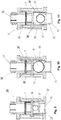
- Figures 9-11 show cross sections in greater detail of the embodiment of the invention, shown in fig. 5 , apart from the fitting 31 to the cladding or insulation. Apart from the seal 30 on fig 10 , are all the reference numerals common for the figures 9, 10 and 11 , and the various reference numerals have been located on the different figures for convenience.
- Fig. 9 shows the liquid leakage detection apparatus in a first position, indicating that no liquid is detected, the ball 18 is in a first, dry, unexpanded state, and the indicator body 16 is in a retracted position.
- Fig. 10 shows the liquid leakage detection apparatus in a second position, indicating that liquid is detected, the ball 18 is in a second, wet expanded state, and the indicator body 16 is in an extended position.
- Fig. 11 shows the liquid leakage detection apparatus in a second position, indicating that liquid is detected, but the ball 18 is has dried and contracted somewhat, yet the indicator body 16 is in an extended position indicating that the presence of liquid has been detected at some stage, and that corrosion could be a problem.
- a latching mechanism (not shown) may be included to prevent inadvertent resetting of the indicator body 16. The latching mechanism may prevent someone from pushing the indicator body into the housing 7.
- Fig. 9 furthermore shows a clearance forming a part of the liquid path 27 between the ball 18 and the indicator body 16 when the ball 18 is in the contracted state, thus allowing liquid to flow into the sample cavity 23 in the indicator body 16.
- the indicator body 16 may be of a translucent material or may include a translucent portion to show that a sample is present in the sample cavity 23.
- the indicator body 16 may also include a coloured portion 32 around a perimeter of the lower part that becomes visible when the indicator body 16 is in an extended position to ease visible reading of the indication of a fluid.
- Drainage holes 35 may be included to prevent excessive accumulation of liquid to allow the plug to act as a drainage plug to prevent further corrosion and to prevent breakage in the event of frost.
- the drainage holes 35 leads excess liquid out through an annular channel 29 formed between the sleeve shaped housing 7 and the hood 15.
- the hood 15 includes an inner ring shaped ledge surrounding an outer portion of a fitting 31, and that is held between a nut portion on the fitting 31 and an edge on the sleeve shaped fitting 7.
- a threaded connection 28 between the fitting 31 and the sleeve shaped housing 7 holds the hood 15 and the sleeve shaped housing 7 to the fitting 31.
- the fitting 31 may form a liquid collecting portion.
- the indicator body 16 may be made of a material that will withstand expansion in the event of frost to prevent breakage of the indicator body 16 and loss of the sample fluid.
- the leakage detection apparatus should be placed in an upright, vertical position to allow the liquid to flow into the sample cavity 23 of the indicator body 16.
- a drainage nipple as shown on fig. 7 may of course also be included in the embodiment shown on the figures 9-11 .
- the ball 18 may, as shown on fig. 10 , form a seal 30 around an upper perimeter of the indicator body 16 to retard evaporation of the fluid sample.
- the fitting 31 includes an upper cladding attachment portion 33 with threads or latching and sealing elements for attaching the fitting 31 to the cladding on the outside of the insulation of the pipe or tube to be monitored.
- the liquid leakage detection apparatus is installed vertically with the fitting 31, in line with the sleeve shaped housing 7, the indicator body 16 and the hood 15.
- the fitting 31 forms an inlet and includes a central bore aligned with the sleeve shaped housing 7.
- the liquid path 27 extends through the bore of the fitting 31, the sleeve shaped housing 31, past the ball 18, through the perforations 22 and into the sample cavity 23.
- the indicator body is held in place in the sleeve shaped housing by friction.
- the friction may be induced by a resilient friction element 36 biased between the sleeve shaped housing 7 and the indicator body 16.
- the resilient friction element 36 may be a separate element or may be formed as an integral part of the sleeve shaped housing 7 or the indicator body 16.
- the invention also includes an insulated pipe with a leakage detection apparatus as described above attached at the outer perimeter of the insulation at the lowermost position on a vertical axis of the outer perimeter of the pipe.
- the fluid sample may be extracted and may be sent to a suitable laboratory for analysis to identify for instance rust or other types of corrosion.
- the sample may also form a smelling sample for indication by a suitably trained dog or other animal.
Landscapes
- General Physics & Mathematics (AREA)
- Physics & Mathematics (AREA)
- Examining Or Testing Airtightness (AREA)
- Life Sciences & Earth Sciences (AREA)
- Hydrology & Water Resources (AREA)
- Health & Medical Sciences (AREA)
- Chemical & Material Sciences (AREA)
- Analytical Chemistry (AREA)
- Biochemistry (AREA)
- General Health & Medical Sciences (AREA)
- Immunology (AREA)
- Pathology (AREA)
- Sampling And Sample Adjustment (AREA)
- Gas-Filled Discharge Tubes (AREA)
- Glass Compositions (AREA)
Priority Applications (1)
| Application Number | Priority Date | Filing Date | Title |
|---|---|---|---|
| PL14773708T PL2979072T3 (pl) | 2013-03-25 | 2014-03-24 | Czujnik wycieku |
Applications Claiming Priority (2)
| Application Number | Priority Date | Filing Date | Title |
|---|---|---|---|
| NO20130423A NO347401B1 (no) | 2013-03-25 | 2013-03-25 | Lekkasjeindikator |
| PCT/NO2014/050042 WO2014158027A1 (en) | 2013-03-25 | 2014-03-24 | Leak indicator |
Publications (3)
| Publication Number | Publication Date |
|---|---|
| EP2979072A1 EP2979072A1 (en) | 2016-02-03 |
| EP2979072A4 EP2979072A4 (en) | 2016-11-09 |
| EP2979072B1 true EP2979072B1 (en) | 2020-09-30 |
Family
ID=51624862
Family Applications (1)
| Application Number | Title | Priority Date | Filing Date |
|---|---|---|---|
| EP14773708.4A Active EP2979072B1 (en) | 2013-03-25 | 2014-03-24 | Leak indicator |
Country Status (9)
| Country | Link |
|---|---|
| US (1) | US10054512B2 (pl) |
| EP (1) | EP2979072B1 (pl) |
| KR (1) | KR102223443B1 (pl) |
| AU (1) | AU2014244627B2 (pl) |
| ES (1) | ES2842351T3 (pl) |
| NO (1) | NO347401B1 (pl) |
| PL (1) | PL2979072T3 (pl) |
| SA (1) | SA515361231B1 (pl) |
| WO (1) | WO2014158027A1 (pl) |
Families Citing this family (2)
| Publication number | Priority date | Publication date | Assignee | Title |
|---|---|---|---|---|
| USD864774S1 (en) * | 2018-07-30 | 2019-10-29 | Healgen Scientific Limited | Liquid sample collector and test device |
| CN109470413B (zh) * | 2018-12-28 | 2020-04-24 | 中石化石油工程技术服务有限公司 | 一种阀门检测装置及其使用方法 |
Family Cites Families (8)
| Publication number | Priority date | Publication date | Assignee | Title |
|---|---|---|---|---|
| DE3605633A1 (de) * | 1986-02-21 | 1987-09-03 | Gerd Neumann | Vorrichtung zur frueherkennung und eingrenzung von wasserschaeden an einem flachdach und verfahren zum anbringen der vorrichtung |
| US5327931A (en) * | 1992-01-31 | 1994-07-12 | Waterguard, Inc. | Flush valve leakage prevention and detection device |
| FR2698953B1 (fr) * | 1992-12-03 | 1995-01-06 | Snecma | Système de distribution de fluides à travers une enveloppe évidée et un couvercle à évent et dispositif de détection de fuites. |
| NO305259B1 (no) * | 1997-04-23 | 1999-04-26 | Shore Tec As | FremgangsmÕte og apparat til bruk ved produksjonstest av en forventet permeabel formasjon |
| US6182507B1 (en) * | 1998-12-08 | 2001-02-06 | The United States Of America As Represented By The Secretary Of The Navy | Mechanical water sensor |
| US6561023B2 (en) * | 2001-04-23 | 2003-05-13 | The United States Of America As Represented By The Secretary Of The Navy | Cellulose-based water sensing actuator |
| US20090095074A1 (en) * | 2007-10-12 | 2009-04-16 | Yevgeniy Vinshtok | Sensor housing |
| EP2762717B1 (en) * | 2013-02-01 | 2016-04-20 | Hanil Tube Corporation | Unheated fuel-line assembly and method of detecting leakage at and/or in a fuel line |
-
2013
- 2013-03-25 NO NO20130423A patent/NO347401B1/no unknown
-
2014
- 2014-03-24 US US14/780,282 patent/US10054512B2/en active Active
- 2014-03-24 WO PCT/NO2014/050042 patent/WO2014158027A1/en not_active Ceased
- 2014-03-24 AU AU2014244627A patent/AU2014244627B2/en not_active Ceased
- 2014-03-24 EP EP14773708.4A patent/EP2979072B1/en active Active
- 2014-03-24 ES ES14773708T patent/ES2842351T3/es active Active
- 2014-03-24 KR KR1020157030150A patent/KR102223443B1/ko active Active
- 2014-03-24 PL PL14773708T patent/PL2979072T3/pl unknown
-
2015
- 2015-09-27 SA SA515361231A patent/SA515361231B1/ar unknown
Non-Patent Citations (1)
| Title |
|---|
| None * |
Also Published As
| Publication number | Publication date |
|---|---|
| KR20150140695A (ko) | 2015-12-16 |
| NO347401B1 (no) | 2023-10-16 |
| EP2979072A1 (en) | 2016-02-03 |
| ES2842351T3 (es) | 2021-07-13 |
| EP2979072A4 (en) | 2016-11-09 |
| US10054512B2 (en) | 2018-08-21 |
| WO2014158027A1 (en) | 2014-10-02 |
| AU2014244627B2 (en) | 2017-02-09 |
| US20160041062A1 (en) | 2016-02-11 |
| NO20130423A1 (no) | 2014-09-26 |
| PL2979072T3 (pl) | 2021-06-28 |
| SA515361231B1 (ar) | 2018-11-28 |
| KR102223443B1 (ko) | 2021-03-08 |
| AU2014244627A1 (en) | 2015-10-22 |
Similar Documents
| Publication | Publication Date | Title |
|---|---|---|
| US20090068060A1 (en) | Corrosion Monitor | |
| AU2012378923B2 (en) | A device for detecting fluid leakage | |
| EP2979072B1 (en) | Leak indicator | |
| RU2350820C2 (ru) | Трубопроводная система | |
| US9513146B2 (en) | Insertion mount device | |
| US10487480B2 (en) | Water leak detection and prevention device | |
| US4849739A (en) | Liquid detector for air pressure type fire sprinkler system | |
| CA2545308A1 (en) | Water ingress detection system | |
| US6272903B1 (en) | Pipeline valve leak indicator | |
| ES2503515A2 (es) | Tubería para conducción de fluidos. | |
| KR20120005865U (ko) | 파이프 부식 검사용 점검구 | |
| JP2015108442A (ja) | トラップ | |
| DK3176341T3 (en) | Flat roof-module kit | |
| US8999723B2 (en) | Transformer hydrogen indicator | |
| JP6375194B2 (ja) | トラップ | |
| CN104374525A (zh) | 检测和定位引导或包含水的设备中的泄漏 | |
| Risi | Performing reliable early leak detection on storage tank terminals: retrofitting of existing facilities and new buildings | |
| ES2613085T3 (es) | Dispositivo de seguridad para una instalación de suministro de gas | |
| JPS61256235A (ja) | 復水貯蔵槽の漏洩検出装置 | |
| GB2166870A (en) | Liquid level detection | |
| JPH0439607B2 (pl) | ||
| JPS6319528A (ja) | 少量の床漏えい水検出装置 | |
| DK146455B (da) | Fremgangsmaade og anlaeg til at overvaage og detektere eventuel utaethed i et roersystem | |
| ZA200604479B (en) | Water ingress detection system |
Legal Events
| Date | Code | Title | Description |
|---|---|---|---|
| PUAI | Public reference made under article 153(3) epc to a published international application that has entered the european phase |
Free format text: ORIGINAL CODE: 0009012 |
|
| 17P | Request for examination filed |
Effective date: 20150923 |
|
| AK | Designated contracting states |
Kind code of ref document: A1 Designated state(s): AL AT BE BG CH CY CZ DE DK EE ES FI FR GB GR HR HU IE IS IT LI LT LU LV MC MK MT NL NO PL PT RO RS SE SI SK SM TR |
|
| AX | Request for extension of the european patent |
Extension state: BA ME |
|
| A4 | Supplementary search report drawn up and despatched |
Effective date: 20161012 |
|
| RIC1 | Information provided on ipc code assigned before grant |
Ipc: G01M 3/04 20060101AFI20161006BHEP Ipc: G01M 3/36 20060101ALI20161006BHEP |
|
| GRAP | Despatch of communication of intention to grant a patent |
Free format text: ORIGINAL CODE: EPIDOSNIGR1 |
|
| STAA | Information on the status of an ep patent application or granted ep patent |
Free format text: STATUS: GRANT OF PATENT IS INTENDED |
|
| INTG | Intention to grant announced |
Effective date: 20200608 |
|
| GRAS | Grant fee paid |
Free format text: ORIGINAL CODE: EPIDOSNIGR3 |
|
| GRAA | (expected) grant |
Free format text: ORIGINAL CODE: 0009210 |
|
| STAA | Information on the status of an ep patent application or granted ep patent |
Free format text: STATUS: THE PATENT HAS BEEN GRANTED |
|
| AK | Designated contracting states |
Kind code of ref document: B1 Designated state(s): AL AT BE BG CH CY CZ DE DK EE ES FI FR GB GR HR HU IE IS IT LI LT LU LV MC MK MT NL NO PL PT RO RS SE SI SK SM TR |
|
| AX | Request for extension of the european patent |
Extension state: BA ME |
|
| REG | Reference to a national code |
Ref country code: GB Ref legal event code: FG4D Ref country code: CH Ref legal event code: EP |
|
| REG | Reference to a national code |
Ref country code: AT Ref legal event code: REF Ref document number: 1319293 Country of ref document: AT Kind code of ref document: T Effective date: 20201015 |
|
| REG | Reference to a national code |
Ref country code: DE Ref legal event code: R096 Ref document number: 602014070779 Country of ref document: DE |
|
| REG | Reference to a national code |
Ref country code: IE Ref legal event code: FG4D |
|
| REG | Reference to a national code |
Ref country code: NL Ref legal event code: FP |
|
| PG25 | Lapsed in a contracting state [announced via postgrant information from national office to epo] |
Ref country code: HR Free format text: LAPSE BECAUSE OF FAILURE TO SUBMIT A TRANSLATION OF THE DESCRIPTION OR TO PAY THE FEE WITHIN THE PRESCRIBED TIME-LIMIT Effective date: 20200930 Ref country code: SE Free format text: LAPSE BECAUSE OF FAILURE TO SUBMIT A TRANSLATION OF THE DESCRIPTION OR TO PAY THE FEE WITHIN THE PRESCRIBED TIME-LIMIT Effective date: 20200930 Ref country code: BG Free format text: LAPSE BECAUSE OF FAILURE TO SUBMIT A TRANSLATION OF THE DESCRIPTION OR TO PAY THE FEE WITHIN THE PRESCRIBED TIME-LIMIT Effective date: 20201230 Ref country code: NO Free format text: LAPSE BECAUSE OF FAILURE TO SUBMIT A TRANSLATION OF THE DESCRIPTION OR TO PAY THE FEE WITHIN THE PRESCRIBED TIME-LIMIT Effective date: 20201230 Ref country code: GR Free format text: LAPSE BECAUSE OF FAILURE TO SUBMIT A TRANSLATION OF THE DESCRIPTION OR TO PAY THE FEE WITHIN THE PRESCRIBED TIME-LIMIT Effective date: 20201231 Ref country code: FI Free format text: LAPSE BECAUSE OF FAILURE TO SUBMIT A TRANSLATION OF THE DESCRIPTION OR TO PAY THE FEE WITHIN THE PRESCRIBED TIME-LIMIT Effective date: 20200930 |
|
| REG | Reference to a national code |
Ref country code: AT Ref legal event code: MK05 Ref document number: 1319293 Country of ref document: AT Kind code of ref document: T Effective date: 20200930 |
|
| PG25 | Lapsed in a contracting state [announced via postgrant information from national office to epo] |
Ref country code: RS Free format text: LAPSE BECAUSE OF FAILURE TO SUBMIT A TRANSLATION OF THE DESCRIPTION OR TO PAY THE FEE WITHIN THE PRESCRIBED TIME-LIMIT Effective date: 20200930 Ref country code: LV Free format text: LAPSE BECAUSE OF FAILURE TO SUBMIT A TRANSLATION OF THE DESCRIPTION OR TO PAY THE FEE WITHIN THE PRESCRIBED TIME-LIMIT Effective date: 20200930 |
|
| REG | Reference to a national code |
Ref country code: LT Ref legal event code: MG4D |
|
| PG25 | Lapsed in a contracting state [announced via postgrant information from national office to epo] |
Ref country code: SM Free format text: LAPSE BECAUSE OF FAILURE TO SUBMIT A TRANSLATION OF THE DESCRIPTION OR TO PAY THE FEE WITHIN THE PRESCRIBED TIME-LIMIT Effective date: 20200930 Ref country code: RO Free format text: LAPSE BECAUSE OF FAILURE TO SUBMIT A TRANSLATION OF THE DESCRIPTION OR TO PAY THE FEE WITHIN THE PRESCRIBED TIME-LIMIT Effective date: 20200930 Ref country code: PT Free format text: LAPSE BECAUSE OF FAILURE TO SUBMIT A TRANSLATION OF THE DESCRIPTION OR TO PAY THE FEE WITHIN THE PRESCRIBED TIME-LIMIT Effective date: 20210201 Ref country code: LT Free format text: LAPSE BECAUSE OF FAILURE TO SUBMIT A TRANSLATION OF THE DESCRIPTION OR TO PAY THE FEE WITHIN THE PRESCRIBED TIME-LIMIT Effective date: 20200930 Ref country code: EE Free format text: LAPSE BECAUSE OF FAILURE TO SUBMIT A TRANSLATION OF THE DESCRIPTION OR TO PAY THE FEE WITHIN THE PRESCRIBED TIME-LIMIT Effective date: 20200930 Ref country code: CZ Free format text: LAPSE BECAUSE OF FAILURE TO SUBMIT A TRANSLATION OF THE DESCRIPTION OR TO PAY THE FEE WITHIN THE PRESCRIBED TIME-LIMIT Effective date: 20200930 |
|
| PG25 | Lapsed in a contracting state [announced via postgrant information from national office to epo] |
Ref country code: IS Free format text: LAPSE BECAUSE OF FAILURE TO SUBMIT A TRANSLATION OF THE DESCRIPTION OR TO PAY THE FEE WITHIN THE PRESCRIBED TIME-LIMIT Effective date: 20210130 Ref country code: AL Free format text: LAPSE BECAUSE OF FAILURE TO SUBMIT A TRANSLATION OF THE DESCRIPTION OR TO PAY THE FEE WITHIN THE PRESCRIBED TIME-LIMIT Effective date: 20200930 Ref country code: AT Free format text: LAPSE BECAUSE OF FAILURE TO SUBMIT A TRANSLATION OF THE DESCRIPTION OR TO PAY THE FEE WITHIN THE PRESCRIBED TIME-LIMIT Effective date: 20200930 |
|
| PG25 | Lapsed in a contracting state [announced via postgrant information from national office to epo] |
Ref country code: SK Free format text: LAPSE BECAUSE OF FAILURE TO SUBMIT A TRANSLATION OF THE DESCRIPTION OR TO PAY THE FEE WITHIN THE PRESCRIBED TIME-LIMIT Effective date: 20200930 |
|
| REG | Reference to a national code |
Ref country code: DE Ref legal event code: R097 Ref document number: 602014070779 Country of ref document: DE |
|
| REG | Reference to a national code |
Ref country code: ES Ref legal event code: FG2A Ref document number: 2842351 Country of ref document: ES Kind code of ref document: T3 Effective date: 20210713 |
|
| PLBE | No opposition filed within time limit |
Free format text: ORIGINAL CODE: 0009261 |
|
| STAA | Information on the status of an ep patent application or granted ep patent |
Free format text: STATUS: NO OPPOSITION FILED WITHIN TIME LIMIT |
|
| PG25 | Lapsed in a contracting state [announced via postgrant information from national office to epo] |
Ref country code: DK Free format text: LAPSE BECAUSE OF FAILURE TO SUBMIT A TRANSLATION OF THE DESCRIPTION OR TO PAY THE FEE WITHIN THE PRESCRIBED TIME-LIMIT Effective date: 20200930 |
|
| 26N | No opposition filed |
Effective date: 20210701 |
|
| PG25 | Lapsed in a contracting state [announced via postgrant information from national office to epo] |
Ref country code: MC Free format text: LAPSE BECAUSE OF FAILURE TO SUBMIT A TRANSLATION OF THE DESCRIPTION OR TO PAY THE FEE WITHIN THE PRESCRIBED TIME-LIMIT Effective date: 20200930 |
|
| REG | Reference to a national code |
Ref country code: CH Ref legal event code: PL |
|
| PG25 | Lapsed in a contracting state [announced via postgrant information from national office to epo] |
Ref country code: SI Free format text: LAPSE BECAUSE OF FAILURE TO SUBMIT A TRANSLATION OF THE DESCRIPTION OR TO PAY THE FEE WITHIN THE PRESCRIBED TIME-LIMIT Effective date: 20200930 |
|
| PG25 | Lapsed in a contracting state [announced via postgrant information from national office to epo] |
Ref country code: IE Free format text: LAPSE BECAUSE OF NON-PAYMENT OF DUE FEES Effective date: 20210324 Ref country code: LI Free format text: LAPSE BECAUSE OF NON-PAYMENT OF DUE FEES Effective date: 20210331 Ref country code: LU Free format text: LAPSE BECAUSE OF NON-PAYMENT OF DUE FEES Effective date: 20210324 Ref country code: CH Free format text: LAPSE BECAUSE OF NON-PAYMENT OF DUE FEES Effective date: 20210331 |
|
| PG25 | Lapsed in a contracting state [announced via postgrant information from national office to epo] |
Ref country code: IS Free format text: LAPSE BECAUSE OF FAILURE TO SUBMIT A TRANSLATION OF THE DESCRIPTION OR TO PAY THE FEE WITHIN THE PRESCRIBED TIME-LIMIT Effective date: 20210130 |
|
| PG25 | Lapsed in a contracting state [announced via postgrant information from national office to epo] |
Ref country code: HU Free format text: LAPSE BECAUSE OF FAILURE TO SUBMIT A TRANSLATION OF THE DESCRIPTION OR TO PAY THE FEE WITHIN THE PRESCRIBED TIME-LIMIT; INVALID AB INITIO Effective date: 20140324 |
|
| PG25 | Lapsed in a contracting state [announced via postgrant information from national office to epo] |
Ref country code: CY Free format text: LAPSE BECAUSE OF FAILURE TO SUBMIT A TRANSLATION OF THE DESCRIPTION OR TO PAY THE FEE WITHIN THE PRESCRIBED TIME-LIMIT Effective date: 20200930 |
|
| PGFP | Annual fee paid to national office [announced via postgrant information from national office to epo] |
Ref country code: NL Payment date: 20240318 Year of fee payment: 11 |
|
| PG25 | Lapsed in a contracting state [announced via postgrant information from national office to epo] |
Ref country code: MK Free format text: LAPSE BECAUSE OF FAILURE TO SUBMIT A TRANSLATION OF THE DESCRIPTION OR TO PAY THE FEE WITHIN THE PRESCRIBED TIME-LIMIT Effective date: 20200930 |
|
| PGFP | Annual fee paid to national office [announced via postgrant information from national office to epo] |
Ref country code: DE Payment date: 20240319 Year of fee payment: 11 Ref country code: GB Payment date: 20240318 Year of fee payment: 11 |
|
| PGFP | Annual fee paid to national office [announced via postgrant information from national office to epo] |
Ref country code: TR Payment date: 20240312 Year of fee payment: 11 Ref country code: PL Payment date: 20240306 Year of fee payment: 11 Ref country code: IT Payment date: 20240321 Year of fee payment: 11 Ref country code: FR Payment date: 20240315 Year of fee payment: 11 Ref country code: BE Payment date: 20240318 Year of fee payment: 11 |
|
| PGFP | Annual fee paid to national office [announced via postgrant information from national office to epo] |
Ref country code: ES Payment date: 20240412 Year of fee payment: 11 |
|
| PG25 | Lapsed in a contracting state [announced via postgrant information from national office to epo] |
Ref country code: MT Free format text: LAPSE BECAUSE OF FAILURE TO SUBMIT A TRANSLATION OF THE DESCRIPTION OR TO PAY THE FEE WITHIN THE PRESCRIBED TIME-LIMIT Effective date: 20200930 |
|
| REG | Reference to a national code |
Ref country code: DE Ref legal event code: R119 Ref document number: 602014070779 Country of ref document: DE |
|
| REG | Reference to a national code |
Ref country code: NL Ref legal event code: MM Effective date: 20250401 |
|
| GBPC | Gb: european patent ceased through non-payment of renewal fee |
Effective date: 20250324 |
|
| REG | Reference to a national code |
Ref country code: BE Ref legal event code: MM Effective date: 20250331 |
|
| PG25 | Lapsed in a contracting state [announced via postgrant information from national office to epo] |
Ref country code: NL Free format text: LAPSE BECAUSE OF NON-PAYMENT OF DUE FEES Effective date: 20250401 |
|
| PG25 | Lapsed in a contracting state [announced via postgrant information from national office to epo] |
Ref country code: DE Free format text: LAPSE BECAUSE OF NON-PAYMENT OF DUE FEES Effective date: 20251001 |
|
| PG25 | Lapsed in a contracting state [announced via postgrant information from national office to epo] |
Ref country code: GB Free format text: LAPSE BECAUSE OF NON-PAYMENT OF DUE FEES Effective date: 20250324 |
|
| PG25 | Lapsed in a contracting state [announced via postgrant information from national office to epo] |
Ref country code: FR Free format text: LAPSE BECAUSE OF NON-PAYMENT OF DUE FEES Effective date: 20250331 Ref country code: IT Free format text: LAPSE BECAUSE OF NON-PAYMENT OF DUE FEES Effective date: 20250324 |
|
| PG25 | Lapsed in a contracting state [announced via postgrant information from national office to epo] |
Ref country code: BE Free format text: LAPSE BECAUSE OF NON-PAYMENT OF DUE FEES Effective date: 20250331 |