EP2979014B1 - Sterile verbindung-/lösungskupplung und verfahren - Google Patents
Sterile verbindung-/lösungskupplung und verfahren Download PDFInfo
- Publication number
- EP2979014B1 EP2979014B1 EP14774870.1A EP14774870A EP2979014B1 EP 2979014 B1 EP2979014 B1 EP 2979014B1 EP 14774870 A EP14774870 A EP 14774870A EP 2979014 B1 EP2979014 B1 EP 2979014B1
- Authority
- EP
- European Patent Office
- Prior art keywords
- valve
- door
- valve port
- housing
- members
- Prior art date
- Legal status (The legal status is an assumption and is not a legal conclusion. Google has not performed a legal analysis and makes no representation as to the accuracy of the status listed.)
- Active
Links
- 238000000034 method Methods 0.000 title claims description 16
- 230000008878 coupling Effects 0.000 title claims description 8
- 238000010168 coupling process Methods 0.000 title claims description 8
- 238000005859 coupling reaction Methods 0.000 title claims description 8
- 239000012530 fluid Substances 0.000 claims description 78
- 238000012546 transfer Methods 0.000 claims description 37
- 238000004891 communication Methods 0.000 claims description 19
- 238000006073 displacement reaction Methods 0.000 claims description 10
- 230000036512 infertility Effects 0.000 description 11
- 230000008569 process Effects 0.000 description 9
- 239000012528 membrane Substances 0.000 description 7
- 238000005070 sampling Methods 0.000 description 7
- 239000000463 material Substances 0.000 description 6
- 239000004033 plastic Substances 0.000 description 4
- 230000001954 sterilising effect Effects 0.000 description 4
- 238000010977 unit operation Methods 0.000 description 4
- 230000000712 assembly Effects 0.000 description 3
- 238000000429 assembly Methods 0.000 description 3
- 229920001971 elastomer Polymers 0.000 description 3
- 239000011521 glass Substances 0.000 description 3
- 239000007788 liquid Substances 0.000 description 3
- 239000005060 rubber Substances 0.000 description 3
- 239000007787 solid Substances 0.000 description 3
- 238000004659 sterilization and disinfection Methods 0.000 description 3
- 239000004734 Polyphenylene sulfide Substances 0.000 description 2
- 229920000491 Polyphenylsulfone Polymers 0.000 description 2
- 239000003570 air Substances 0.000 description 2
- 229960000074 biopharmaceutical Drugs 0.000 description 2
- 238000010276 construction Methods 0.000 description 2
- 238000011109 contamination Methods 0.000 description 2
- 238000003754 machining Methods 0.000 description 2
- 238000004519 manufacturing process Methods 0.000 description 2
- 230000013011 mating Effects 0.000 description 2
- 230000007246 mechanism Effects 0.000 description 2
- 238000000465 moulding Methods 0.000 description 2
- 229920002492 poly(sulfone) Polymers 0.000 description 2
- 229920000069 polyphenylene sulfide Polymers 0.000 description 2
- 229920005989 resin Polymers 0.000 description 2
- 239000011347 resin Substances 0.000 description 2
- 239000010935 stainless steel Substances 0.000 description 2
- 229910001220 stainless steel Inorganic materials 0.000 description 2
- 239000000126 substance Substances 0.000 description 2
- LTKHPMDRMUCUEB-IBGZPJMESA-N CB3717 Chemical compound C=1C=C2NC(N)=NC(=O)C2=CC=1CN(CC#C)C1=CC=C(C(=O)N[C@@H](CCC(O)=O)C(O)=O)C=C1 LTKHPMDRMUCUEB-IBGZPJMESA-N 0.000 description 1
- 229920002943 EPDM rubber Polymers 0.000 description 1
- 229910052782 aluminium Inorganic materials 0.000 description 1
- XAGFODPZIPBFFR-UHFFFAOYSA-N aluminium Chemical compound [Al] XAGFODPZIPBFFR-UHFFFAOYSA-N 0.000 description 1
- 239000012080 ambient air Substances 0.000 description 1
- 230000004888 barrier function Effects 0.000 description 1
- 230000000903 blocking effect Effects 0.000 description 1
- 239000000872 buffer Substances 0.000 description 1
- 238000004113 cell culture Methods 0.000 description 1
- 230000008859 change Effects 0.000 description 1
- 238000004140 cleaning Methods 0.000 description 1
- 230000006835 compression Effects 0.000 description 1
- 238000007906 compression Methods 0.000 description 1
- 239000000356 contaminant Substances 0.000 description 1
- 230000001419 dependent effect Effects 0.000 description 1
- 238000013461 design Methods 0.000 description 1
- 230000000694 effects Effects 0.000 description 1
- 230000007613 environmental effect Effects 0.000 description 1
- 238000001914 filtration Methods 0.000 description 1
- 239000007789 gas Substances 0.000 description 1
- 238000009434 installation Methods 0.000 description 1
- 238000005304 joining Methods 0.000 description 1
- 239000007769 metal material Substances 0.000 description 1
- 230000000813 microbial effect Effects 0.000 description 1
- 238000002156 mixing Methods 0.000 description 1
- 239000000203 mixture Substances 0.000 description 1
- 229920003052 natural elastomer Polymers 0.000 description 1
- 229920001194 natural rubber Polymers 0.000 description 1
- 229920005548 perfluoropolymer Polymers 0.000 description 1
- 229920000098 polyolefin Polymers 0.000 description 1
- 229920001296 polysiloxane Polymers 0.000 description 1
- 239000004810 polytetrafluoroethylene Substances 0.000 description 1
- 229920001343 polytetrafluoroethylene Polymers 0.000 description 1
- 238000004886 process control Methods 0.000 description 1
- 238000012545 processing Methods 0.000 description 1
- 230000000069 prophylactic effect Effects 0.000 description 1
- 230000001681 protective effect Effects 0.000 description 1
- 238000003908 quality control method Methods 0.000 description 1
- 239000012858 resilient material Substances 0.000 description 1
- 238000005096 rolling process Methods 0.000 description 1
- 238000007789 sealing Methods 0.000 description 1
- 238000003860 storage Methods 0.000 description 1
- 229920003051 synthetic elastomer Polymers 0.000 description 1
- 239000005061 synthetic rubber Substances 0.000 description 1
- 229920001169 thermoplastic Polymers 0.000 description 1
- 229920002725 thermoplastic elastomer Polymers 0.000 description 1
- 239000004416 thermosoftening plastic Substances 0.000 description 1
- 150000003673 urethanes Chemical class 0.000 description 1
Images


Classifications
-
- A—HUMAN NECESSITIES
- A61—MEDICAL OR VETERINARY SCIENCE; HYGIENE
- A61M—DEVICES FOR INTRODUCING MEDIA INTO, OR ONTO, THE BODY; DEVICES FOR TRANSDUCING BODY MEDIA OR FOR TAKING MEDIA FROM THE BODY; DEVICES FOR PRODUCING OR ENDING SLEEP OR STUPOR
- A61M39/00—Tubes, tube connectors, tube couplings, valves, access sites or the like, specially adapted for medical use
- A61M39/10—Tube connectors; Tube couplings
- A61M39/16—Tube connectors; Tube couplings having provision for disinfection or sterilisation
- A61M39/18—Methods or apparatus for making the connection under sterile conditions, i.e. sterile docking
-
- A—HUMAN NECESSITIES
- A61—MEDICAL OR VETERINARY SCIENCE; HYGIENE
- A61M—DEVICES FOR INTRODUCING MEDIA INTO, OR ONTO, THE BODY; DEVICES FOR TRANSDUCING BODY MEDIA OR FOR TAKING MEDIA FROM THE BODY; DEVICES FOR PRODUCING OR ENDING SLEEP OR STUPOR
- A61M39/00—Tubes, tube connectors, tube couplings, valves, access sites or the like, specially adapted for medical use
- A61M39/22—Valves or arrangement of valves
- A61M39/26—Valves closing automatically on disconnecting the line and opening on reconnection thereof
-
- F—MECHANICAL ENGINEERING; LIGHTING; HEATING; WEAPONS; BLASTING
- F16—ENGINEERING ELEMENTS AND UNITS; GENERAL MEASURES FOR PRODUCING AND MAINTAINING EFFECTIVE FUNCTIONING OF MACHINES OR INSTALLATIONS; THERMAL INSULATION IN GENERAL
- F16L—PIPES; JOINTS OR FITTINGS FOR PIPES; SUPPORTS FOR PIPES, CABLES OR PROTECTIVE TUBING; MEANS FOR THERMAL INSULATION IN GENERAL
- F16L37/00—Couplings of the quick-acting type
- F16L37/28—Couplings of the quick-acting type with fluid cut-off means
- F16L37/30—Couplings of the quick-acting type with fluid cut-off means with fluid cut-off means in each of two pipe-end fittings
- F16L37/32—Couplings of the quick-acting type with fluid cut-off means with fluid cut-off means in each of two pipe-end fittings at least one of two lift valves being opened automatically when the coupling is applied
- F16L37/36—Couplings of the quick-acting type with fluid cut-off means with fluid cut-off means in each of two pipe-end fittings at least one of two lift valves being opened automatically when the coupling is applied with two lift valves being actuated to initiate the flow through the coupling after the two coupling parts are locked against withdrawal
-
- F—MECHANICAL ENGINEERING; LIGHTING; HEATING; WEAPONS; BLASTING
- F16—ENGINEERING ELEMENTS AND UNITS; GENERAL MEASURES FOR PRODUCING AND MAINTAINING EFFECTIVE FUNCTIONING OF MACHINES OR INSTALLATIONS; THERMAL INSULATION IN GENERAL
- F16L—PIPES; JOINTS OR FITTINGS FOR PIPES; SUPPORTS FOR PIPES, CABLES OR PROTECTIVE TUBING; MEANS FOR THERMAL INSULATION IN GENERAL
- F16L37/00—Couplings of the quick-acting type
- F16L37/28—Couplings of the quick-acting type with fluid cut-off means
- F16L37/30—Couplings of the quick-acting type with fluid cut-off means with fluid cut-off means in each of two pipe-end fittings
- F16L37/367—Couplings of the quick-acting type with fluid cut-off means with fluid cut-off means in each of two pipe-end fittings with two gate valves or sliding valves
-
- F—MECHANICAL ENGINEERING; LIGHTING; HEATING; WEAPONS; BLASTING
- F16—ENGINEERING ELEMENTS AND UNITS; GENERAL MEASURES FOR PRODUCING AND MAINTAINING EFFECTIVE FUNCTIONING OF MACHINES OR INSTALLATIONS; THERMAL INSULATION IN GENERAL
- F16L—PIPES; JOINTS OR FITTINGS FOR PIPES; SUPPORTS FOR PIPES, CABLES OR PROTECTIVE TUBING; MEANS FOR THERMAL INSULATION IN GENERAL
- F16L55/00—Devices or appurtenances for use in, or in connection with, pipes or pipe systems
- F16L55/07—Arrangement or mounting of devices, e.g. valves, for venting or aerating or draining
-
- F—MECHANICAL ENGINEERING; LIGHTING; HEATING; WEAPONS; BLASTING
- F16—ENGINEERING ELEMENTS AND UNITS; GENERAL MEASURES FOR PRODUCING AND MAINTAINING EFFECTIVE FUNCTIONING OF MACHINES OR INSTALLATIONS; THERMAL INSULATION IN GENERAL
- F16L—PIPES; JOINTS OR FITTINGS FOR PIPES; SUPPORTS FOR PIPES, CABLES OR PROTECTIVE TUBING; MEANS FOR THERMAL INSULATION IN GENERAL
- F16L2201/00—Special arrangements for pipe couplings
- F16L2201/40—Special arrangements for pipe couplings for special environments
- F16L2201/44—Special arrangements for pipe couplings for special environments sterile
Definitions
- the embodiments disclosed herein relate to the transfer of media, such as liquids, into or from a container or the like.
- the embodiments disclosed herein relate to a fluid transfer device in the form of a connector or valve, enabling good sterile fluid transfer between two systems.
- biochemical fluid is often contained in an aseptically “closed” fermenting tank, bioreactor, or like fluid receptacle, wherein the fluid is processed over comparatively long periods of time, under diverse and changing chemical and environmental conditions.
- US 5 492 147 A discloses a dry break coupling for joining together opposing passageways. It comprises a male member and a female member, each of which including a resiliently deformable rubber flap with cross-hair slits in front of the respective valve components. Upon coupling, both rubber flaps are strongly deformed and accommodated in a common pocket formed between parts of the male member and the female member so that this pocket cannot be assigned to a specific one of the male member and the female member.
- WO 2004/082756 A1 discloses a valved male luer connector comprising a sleeve made of resilient material and having an opening. This connector is similar to the male member of the coupling known from US 5 492 147 A .
- the connector assembly described in WO 98/50105 A1 includes removable stripout layers in front of each of the cou-pleable connector fittings, which are not accomodated in any pockets but are to be discarded.
- US 2003/030272 A1 discloses a connection system in which a rolling membrane having a pull grip is disposed in front of each of the end parts to be connected. This design is similar to that known from WO 98/50105 A1 .
- the present invention relates to a fluid transfer device and to a method of creating a sterile connection between first and second valve members of a fluid transfer device and is defined in claims 1 and 5, respectively.
- Advantageous versions of the invention follow from the dependent claims.
- Embodiments disclosed herein provide a fluid transfer device that allows for wet connections under pressure, allows the connection to be reversed, and allows the connection to be reconnected, while leaving the connectors sterile and reusable.
- the device is in the form of a connector or valve.
- the device includes a first member or housing and a second member or housing, one adapted to receive the other in locking engagement upon actuation of the device to create fluid communication between the two in a sterile manner.
- Each of the members or housings includes a door that when opened, allows a valve sleeve of one member to be displaced into the other member to allow fluid to be transferred. When fluid transfer is complete, the valve sleeve can be retracted, and the doors closed.
- a fluid transfer device comprising a first member or housing, the first member or housing comprising a first body member having a port and a grooved surface, and a first base having an outlet.
- the device also includes a second member or housing, the second member or housing comprising a second body member, a second member valve sleeve member having at least one thread configured to be engaged in the grooved surface of the first body member, and a second inner body having an inlet.
- the second member valve sleeve member is linearly displaceable into and out of the first body member to create (and eliminate) fluid communication between the inlet and the outlet.
- the fluid transfer device includes first and second members or housings, which can be engaged or coupled and locked together.
- the act or acts of engagement or coupling, and locking of the two members or housings also creates sterile fluid communication between the two members or housings, and thus between valve members carried by the two members or housings.
- the act or acts of engaging or coupling, and locking the two members or housings creates sterile fluid communication by actuating one or more doors within the device to open positions.
- the act or acts of engaging and coupling, and locking the two members or housings is carried out by relative movement of one member or housing with respect to the other.
- the relative movement includes rotational movement.
- the rotational movement includes rotating the first and second members or housings in opposite directions.
- the relative movement includes linear movement.
- the linear movement includes moving the first and second members or housings in the same direction.
- valve member carried by one of the members or housings into a valve member carried by the other member or housing is effectuated, such as by applying a rotational and/or axial force to one of the valve members.
- Suitable materials of construction include materials capable of withstanding the conditions typically encountered by such devices, including those of sterilization. Suitable materials include but are not limited to plastic, stainless steel and aluminum. Suitable plastic materials may include but are not limited to polysulfone, glass filled polysulfone, polyphenylene sulfide, glass filled polyphenylene sulfide, polyphenyl sulfone and glass filled polyphenyl sulfone are all acceptable materials due to their biocompatibility, chemical, heat and creep resistance. The plastic components of said connector may be formed by machining or molding.
- seals used in the embodiments disclosed herein can be made of but not limited to silicone, rubber, including natural and synthetic rubbers, thermoplastic elastomers, polyolefins, PTFE, thermoplastic perfluoropolymer resins, urethanes, EPDM rubber, PDDF resins etc.
- Fluids to be transferred include liquids and gases.
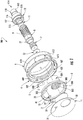
- first member or housing 100 of the fluid transfer device in accordance with certain embodiments, comprising a first sterility housing plate 1 having a port 30, which is preferably circular, that may be closed or blocked by a movable door 2.
- Door 2 includes an axially extending shaft member 32 that fits into aperture 31 on first sterility housing plate 1 and about which the door 2 is pivotable to block or unblock the port 30. The door 2, when opened, can be moved inside an isolated pocket (not shown) within the device to protect the internal chamber of the device from anything that may be on the external face of the door.
- the first member or housing 100 also includes a first body member 3, which includes an aperture 33 that receives an axially extending shaft member 32' of door 2, and is sealed with O-ring 10.
- the door is pivotable about the axis defined by shaft member 32', between the sterility housing plate 1 and the body member 3, to allow or prohibit fluid communication from the port 30 in plate 1, through port 303, to the cylindrical member 304 of first body member 3.
- the first body member 3 has a base 300, an axially extending annular shoulder 41, and an outer annular rim 302 formed radially outwardly from the shoulder 41 and extending axially.
- the member 3 also includes a port 303 that leads to cylindrical member 304 extending axially from the base 300 in a direction opposite that of axially extending rim 302.
- the cylindrical member 304 includes an internal groove or grooves 305 formed in the inner cylindrical wall of the cylindrical member 304. As best seen in FIG. 3 , the groove or grooves 305 terminate prior to the free end of the cylindrical member 304.
- a door lever 5 sits on top of base 300 of the body member 3.
- the door lever 5 has an axially extending end portion 5' that sits in a slot defined by two spaced axially extending protrusions 80, 81 on the base 300 ( FIG. 2 ).
- the door lever 5 is attached to the door by an opening in the lever sliding over a feature on shaft member 32'.
- the first member or housing 100 also includes first bayonet ring 4, which preferably has a knurled circumferential outer surface as shown, to facilitate the user grasping the ring and rotating it.
- the bayonet ring 4 has an inner annular shoulder 420 and a keyed locking mechanism coupled thereto for attaching to the second member 200 as discussed in greater detail below.
- the locking mechanism includes a plurality of slots 406 spaced along the perimeter of the shoulder 420, each slot defined by an L-shaped member 409 that extends axially from the shoulder 420. Positioned between the spaced slots is a plurality of spaced stopping members 407.
- the first member or housing 100 includes inner body member 7 that is surrounded by valve shutoff sleeve 8, is positioned in the cylindrical member 304 and sits over wiper seal 12.
- the sleeve 8 is generally cylindrical, and includes an outer circumferential radially extending flange 77 that serves as a seat for biasing member or spring 9, which fits over the outer cylindrical wall of the sleeve 8.
- the first member or housing 100 also includes first base member 13, which includes an axially extending generally cylindrical member 113 terminating in a free distal end having distal opening or outlet 114, and extending axially to a free proximal end having a proximal end 115.
- the distal region of the member 13 tapers radially outwardly towards the proximal end, thereby forming a shoulder 118. This creates a region of increase radial thickness that helps act as a barb-like fitting and facilitates connection to a tube or the like.
- the base member 13 includes a generally frusto-conical region 116 that surrounds cylindrical member 113, the region 116 having a circumferential radially extending flange 117 that sits on the rim of the cylindrical member 304 when in the assembled condition ( FIG. 3 ).
- An annular groove 119 in the proximal region of the member 113 receives O-ring 11 to seal against the sleeve 8, as best seen in FIG. 3 .
- the second member 200 includes a second sterility housing plate 19 having a port 23, which is preferably circular, that may be closed or blocked by movable second door 22.
- Door 22 includes an axially extending shaft member 24 that fits into aperture 21 on second sterility housing plate 19 and about which the door 22 is pivotable to block or unblock the port 23.
- the door 22 is sealed in aperture 21 by door shaft seal 26.
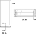
- Overmolded inner sleeve 50 includes tubular member 50A that is positioned around spring 800 and poppet 60, and over-mold seal 50B that seats in an annular groove at the base of the tubular member 50A, as shown in detail in FIGS. 8A and 8B .
- a connector body 70 has an annular radially extending flange 71 having a diameter greater than the inner diameter of the tubular member 50A, allowing the flange 71 to sit on the free end rim of the tubular member 50A a shown in FIG. 7 .
- the portion of connector body 70 below the flange 71 has an outer diameter less than an inner diameter of the tubular member 50A, allowing that portion to sit inside the tubular member 50A.
- the portion of connector body 70 above the flange 71 has an outer diameter less than the inner diameter of the lower free end of inner body 90, which is reduced in thickness relative to the remainder of inner body 90, allowing that portion to sit inside the inner body 90.
- the inner body 90 includes a lower cylindrical region 91, an intermediate frusto-conical region 92, and an upper cylindrical region 93.
- the upper cylindrical region 93 includes a portion that extends radially outwardly towards the intermediate frusto-conical region 92, thereby forming a shoulder 94. This region of increase radial thickness helps acts as a barb-like fitting and facilitates connection to a tube or the like.
- the second member 200 also includes a generally cylindrical second member valve sleeve 110, which includes a proximal free end 111 formed with an external thread or threads 112 configured to engage the groove or grooves 305 in the first member 100.
- a circumferential groove 213 is provided to receive O-ring 127 that seals against cylindrical member 130 of the second body 150 as discussed below.
- Distal free end 216 of the sleeve 110 includes a plurality of spaced slots 217 that receive corresponding spaced projections 141 on nut 140.
- the valve sleeve 110 is positioned over the inner sleeve 50, the connector body 70, and a portion of the lower cylindrical region 91 of the inner body 90.
- the second member 200 includes a second body 150 having a base 151, an axially extending annular shoulder 152, and an outer annular rim 153 formed radially outwardly from the shoulder 152 and extending axially.
- the member 200 includes a port 203 that leads to cylindrical member 130 extending axially from the base 151 in a direction opposite that of axially extending shoulder 152.
- the door 22 is pivotable about the axis defined by shaft member 24, between the sterility housing plate 19 and the second body 150, to allow or prohibit fluid communication from the port 23 in plate 19, through port 203, to the cylindrical member 130 of the second body 150.
- Extending radially outwardly from the rim 153 is a plurality of spaced tabs 155 configured to be received in the slots 406 in the bayonet ring 4 of the first member 100.
- the second member 200 and first member 100 are brought together such that the sterility housing plates 1 and 19 are in opposing relation.
- Relative rotation of the first and second members is created, such as by rotating the bayonet ring 4, causing the tabs 155 in the second member to enter the slots 460 of the first member and lock the members together.
- This relative rotation also causes the alignment of the ports 30 and 23 in the sterility housing plates 1 and 19, which are opposed.
- Fluid communication between the first and second members is created, as the relative rotation also causes the doors 2 and 22, which were previously blocking the ports in the respective sterility housing plates and the ports in the respective body members, to pivot to an open position.
- the second member valve sleeve 110 is axially displaced through the port 23 in sterility housing plate 19, and through the port 30 in sterility housing plate 1.
- the second member valve sleeve 110 is then rotated with nut 140, and is further displaced axially, causing the thread or threads 112 to engage and mate with the groove or grooves 305 in cylindrical member 304 of base 300.
- This causes the axial displacement of valve shutoff sleeve 8, compressing spring 9. A sterile connection is thus made, and fluid can be transferred.
- the second member or housing 200 is retracted from the first member or housing 100.
- the nut 140 is rotated, causing the threads 112 in the second member valve sleeve 110 to disengage with the grooves 305 in the cylindrical member 304 of base 300.
- Spring 9 is no longer compressed, and the valve shutoff sleeve 8 is retracted axially to its original position.
- Wiper seal 12 pushes against base portion 61 and seals and wipes across over-mold seal 50B in tubular member 50A. The seal wipes any liquid that may be present when device is being pulled apart.
- the second member valve sleeve 110 is then removed from the first member, and the bayonet ring 4 is rotated to cause the doors to block the respective ports, thereby maintaining a sterile environment in each member. The process can then be repeated.
- the device can be obtained by simple molding of all the members that constitute it, thus being possible for the device to be a single-use (disposable) device for reasonable cost.
- the device may also be made from conventional machining of its components from the various plastic and metal materials previously listed.
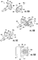
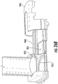
- FIG. 9 illustrates a first alternative embodiment of the fluid transfer device in accordance with certain embodiments.
- the valve operation of this first alternative embodiment is similar to the earlier embodiment; upon connection of the first and second members, sterile fluid communication is established under pressure by causing displacement of one valve member into another.
- the primary difference is in the configuration of the body members or housings and the way the members are brought into engagement or are coupled together.
- the embodiment of FIG. 9 uses a hinged assembly to mate the first and second members or housings.
- FIG. 9 shows first member or housing 400 and second member or housing 320 in a partially assembled condition.
- First member or housing 400 includes body member 401 that has pins 402 on opposite sides of the bottom surface of body member 401 for engagement with a corresponding slot 313 in the body member 301 of second member 320.
- second member 320 includes body member 301 that has pins 312 on opposite sides of the bottom surface of body member 301 for engagement with a corresponding slot 403 in the body member 401 of first member 400.
- Body 301 of second member 320 includes a slidable locking handle assembly 310.
- Body 401 of first member 400 includes a slidable locking handle assembly 410.
- Slidable locking handle assembly 410 is shown in greater detail in FIG. 11A . It includes handle member 415, spaced door shafts 416 (only one shown), door 425 and door stop 426. The door shafts 416 are coupled to the handle member 415 and slide in respective apertures 323 in the body member 401 ( FIG. 12 ).
- the handle assembly 410 includes spaced radially projecting L-shaped flanges 417 (only one shown in FIG. 11A ) that slide on respective opposite edges of the body member 401. When in the closed position, the flanges 417 of handle assembly 410 fit in corresponding reduced in thickness regions in the body member 301, which enables the first and second members to mate. Sliding the handle assembly 410 to the locked position moves the flanges 417 away from the reduced in thickness regions in the body member 301 and cooperatively with handle assembly 310, clamps the first and second members together.
- door 425 is a generally flat member configured to block the port in the second member 320, preventing fluid communication between the first and second members 400, 320.
- the door 425 seals against overmolded gasket 429 that is positioned on the inside of the bottom sterile face 411 of the body member 401.
- An overmolded sterile plate gasket 419 is a perimeter gasket that can be overmolded onto the housing beyond the edge of the sterile plate 411 to seal against the corresponding second member sterile plate when the first and second members are brought together, to keep out contaminants.
- a door stop 426 Projecting upwardly from the door 425 is a door stop 426, which when the door 425 is in the fully open position, abuts against a wall in the body member 401 to delimit the door open position.
- wiper seal 428 is positioned in the body member 401 so that as the door 425 is actuated from its closed to its open position, and vice versa, it contacts the wiper seal 428.
- the wiper seal 428 isolates the door in the open position from the region of the device where fluid flows. This helps to maintain sterile the area where fluid flows.
- the handle assembly 310 of second member 320 has a similar construction, as shown in FIG. 11B . It includes handle member 315, spaced door shafts 316 (only one shown), door 325 and door stop 326. The door shafts 316 are coupled to the handle member 315 and slide in respective apertures (not shown) in the body member 401.
- the handle assembly 310 includes spaced radially projecting L-shaped flanges 317 (only one shown in FIG. 11B ) that slide on respective opposite edges of the body member 301. Sliding the handle assembly 310 to the locked position cooperatively with handle assembly 410 clamps the first and second members together.
- door 325 is a generally flat member configured to close the port in the second member 320, preventing fluid communication between the first and second members 400, 320.
- the door 325 seals against overmolded gasket 329 that is positioned on the inside of the bottom sterile face 311 of the body member 301.
- door stop 326 Projecting upwardly from the door 325 is door stop 326, which when the door 325 is in the fully open position, abuts against a wall in the body member 301 to delimit the door open position.
- wiper seal 328 is positioned in the body member 301 so that as the door 325 is actuated from its closed to its open position, and vice versa, it contacts the wiper seal 328.
- the wiper seal 328 isolates the door in the open position from the region of the device where fluid flows. This helps to maintain sterile the area where fluid flows.
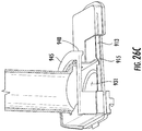
- a vent 625, vent membrane 626 and vent cover 627 may be incorporated into the housing, to draw in ambient air as the valve member is retracted ( FIG. 25 ).
- a suitable membrane 626 is a 0.22 micron sterilizing membrane.
- the vent 626 may include a plurality of holes communicating with the housing interior, which provide a path for air to enter the device when the valve is retracted from the female housing which creates a syringe effect. Air that is pulled in flows through the vent 626 and is sterilized by the membrane 626.
- the vent membrane 626 can be heat sealed to the housing, but gaskets could be used or a pre-existing filter could be attached to a port in the housing.
- the first member 400 and second member 320 are oriented at 90° as shown in FIG. 10A , the members are brought into engagement such that the hinge pin 408 on body member 401 can be inserted into the slot 308 on body member 301 as shown in FIG. 10B , the body members 301, 401 thereby forming a clamshell-like configuration.
- the clamshell is closed by bringing the ends opposite the hinge of members 320 and 400 together, rotating about the axis of the hinge pin 408 as shown by the arrows in FIG. 10B .
- the closed, assembled position is shown in FIG. 10C . In this position, the locking handle assemblies 310, 410 mate so that sliding actuation of one handle also actuates the other. In this position, the valve is closed by doors 425, 325; there is no fluid communication between the first member 400 and the second member 320.
- each of the pins 312 Upon connection of first and second members or housings 400, 320, each of the pins 312 enters a respective slot 403 in the first member 400, and displaces locking member 405 axially, moving it out of the path of slidable handle assembly 410.
- each of the pins 402 enters a respective slot 313 in the second body member 320, and displaces locking member 365 axially, moving it out of the path of slidable handle assembly 310.
- each locking member 365, 405 is an elongated member having a free end that is axially displaceable.
- the locking handle assemblies 310, 410 are actuated by sliding them to the left as depicted in FIG. 10C .
- This actuation simultaneously locks the members 320, 400 together, and moves the doors in each member to the open position, which establishes fluid communication between the first and second members 400, 320.
- the valve member of the second member 320 can be displaced into the valve member of the first member 400, as discussed in greater detail below.
- FIGS. 13A-13C illustrate the first member valve member 450.
- Fitting 413 includes an axially extending generally cylindrical member terminating in a free distal end having distal opening or outlet 414, and extending axially to a free proximal end 435 that sits over the upper free end of cylindrical member 404 of first member 400 ( FIG. 12 ).
- the distal region of the fitting 413 tapers radially outwardly towards the proximal end, thereby forming a shoulder 418. This creates a region of increase radial thickness that helps act as a barb-like fitting and facilitates connection to a tube or the like.
- the fitting 413 includes a generally frusto-conical region 436, the region 436 having a circumferential radially extending flange 437 that sits on the rim of the cylindrical member 404 of first member 400 when in the assembled condition of FIG. 10C .
- Base member 480 has an upper cylindrical portion that seals inside wiper seal 442 with the aid of O-ring 486.
- the lower region 484 of the base member 480 includes a downwardly facing depressor member 481 that in the embodiment shown extends axially from the member 480 and has a semispherical shape. It functions to displace the poppet 560 in the corresponding valve member 350 of the second member 320 upon actuation of the valve, as discussed in greater detail below.
- FIGS. 14A-14E show the valve member 350 of the second member or housing 320.
- the valve member 350 includes upper inner body 510.
- Upper inner body 510 includes an axially extending generally cylindrical member terminating in a free distal end having distal opening or outlet 514, and extending axially to a free proximal end having a proximal end opening 535.
- the distal region of the inner body 510 tapers radially outwardly towards the proximal end, thereby forming a shoulder 518. This creates a region of increase radial thickness that helps act as a barb-like fitting and facilitates connection to a tube or the like.
- the valve member 350 also includes a poppet 560, which includes a solid base portion 561 and a plurality of spaced legs 562 extending axially from the base portion 561.
- the base portion 561 includes a centrally located detent 559 that receives projection 482 on the depressor member 481, as discussed in greater detail below.
- the legs 562 retain a biasing member 580 such as a compression spring or the like that is positioned internally of the legs 562. The opposite end of the biasing member 580 sits in inner body connector 594, which is shown in greater detail in FIG. 14D .
- Valve outer sleeve 570 is a generally cylindrical member that has threads 571 at its lower end for engaging corresponding grooves 318 ( FIG. 12 ) in the generally cylindrical member 404 of first member 400.
- the lower portion of upper inner body 510 sits inside the valve outer sleeve 570 as seen in FIG. 14C , as does inner body connector 594, biasing member 580, poppet 560, and lower inner body 578.
- the lower inner body 578 is generally cylindrical, and as shown in FIG. 14E , includes at its lower end radially inwardly extending flanges 577, which hold an overmolded seal 579 to seals against poppet 560.
- valve member 350, 450 into each other is effectuated by applying an axial load.
- the valve member 350 of the second member 320 is linearly displaced into the valve member 450 of the first member 400, and then further displacement of the valve member 350 into the valve member 450 is effectuated by relative rotation of the valve members, such as by rotating the valve member 350 of the second member 320 with knob 599. This rotation causes the thread or threads 571 on the valve outer sleeve 570 to engage the corresponding groove or grooves 318 in the cylindrical member 404 of valve member 450.
- valve member 350 further displaces the valve member 350 into valve member 450, causing the depressor member 481 to contact and displace poppet 560 in a first direction against the bias of biasing member 580.
- Still further rotation causes the threaded end of valve member 350 to engage the radial flange 477 of wiper seal 442, causing the latter to displace in a second direction against the bias of biasing member 479.
- the first and second directions are opposite directions.
- the displacements of the poppet 560 and of the wiper seal 442 create fluid communication between and through the valve members 350, 450.
- FIGS. 15 and 16 illustrate a second alternative embodiment of the fluid transfer device in accordance with certain embodiments.
- the valve operation of this second alternative embodiment is similar to the first alternative embodiment; upon engagement and locking of the first and second members or housings, sterile fluid communication is established under pressure, and displacement of one valve member into another can be carried out.
- the primary difference is in the configuration of the body members or housings and the way the members are brought into engagement.
- the embodiment of FIGS. 15 and 16 involve the alignment of pin and hook features followed by engaging cam locks ( FIG. 16 ) on the faces of the body members or housings.
- FIGS. 15 and 16 show first member or housing 400' and second member or housing 300' in an assembled condition.
- the valve members 350', 450' are the same or essentially the same as the valve members 350 and 450 of the first alternative embodiment, and thus will not be discussed in detail here.
- the housing for the valve members includes a first member or housing 400' having body member 401' that has a shaped bottom region that corresponds to a similarly shaped bottom region of second member or housing 300', allowing the first and second members to mate.
- Each member 400', 300' includes a top plate.
- each member 400', 300' includes a cam slot (only one shown at 490' for first member 400'), that receives a respective cam member (only one shown at 391' for second member 300') on the other member, each cam member being received by the respective cam slot as the two members 400', 300' are engaged and twisted in opposite directions to lock them together.
- Each member 300', 400' carries a respective lever arm 303', 403' arm attached to a respective door 325', 425'.
- Each lever arm is rotatable between a door open and a door closed position.
- Lever arm 403' of first body member 401' has an axially extending hollow leg 426' that mates with a pin (not shown) that extends axially from the second member 301' .
- lever arm 303' of second body member 301' has an axially extending hollow leg 326' that mates with a pin (not shown) in the bottom of first body member 401'.
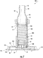
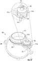
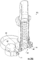
- FIG. 17 illustrates a valve isolator bellows assembly 700.
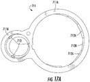
- the assembly 700 includes a bellows 710 that is held by seal retainer member 711 ( FIG. 17A ).
- Seal retainer member 711 includes a first ring 711A that secures bellows 710, and a second ring 711B that connects to cam member 720.
- the first ring 711A includes alternating top and bottom radially inwardly extending flanges 712A, 712B that serve to retain the bellows 710.
- Door 325' also has a ring that connects to cam member 720. Both the door 325' and seal retainer member 711 are moved by rotation of cam 720.
- the cam 720 is generally cylindrical, and includes a plurality of cam slots or grooves 721 (one shown in each of FIGS. 17 and 19A ) formed in its outer side surface. There are corresponding spaced pins 713 on the second ring 711B of the seal retainer member 711 that extend radially inwardly, each of which travels in a respective cam slot 721 of the cam 720.
- the second ring 711B includes three such pins 713, and the cam 720 includes three such cam slots 721, each one corresponding to a respective pin.
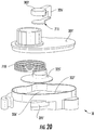
- the door 325' includes a pin (not shown) extending axially downwardly from its bottom to mate with an aperture 306' ( FIG. 20 ) in base 307' of the member 400'.
- the door includes an axially extending button 327 and a plurality (three shown) of spaced axially extending wings 327A that surround the button 327 but do not extend as high.
- the button 327 and wings 327A fit into and are engaged by the open region 331 in the underside of the cam 720, the open region 331 including spaced radially inwardly projecting prongs 332 that fit into the spaces 333 between the wings 327A on the door 325' as shown by the solid arrows in FIG.
- cam 720 includes a keyed pin 723 extending upwardly axially from its top surface to mate with lever arm 303'. Rotation of lever arm 303' causes a corresponding rotation of cam 720. Rotation of the cam moves the door 325' from the open to the closed position (and vice versa), and causes vertical movement of the bellows 710 as the retainer member 711 rides in the cam slots 721 of the cam, as discussed in greater detail below.
- FIG. 17 illustrates the door 325' and bellows 710 in the closed position.
- the door 325' prevents fluid communication between the valve members, and the bellows 710 is sealed against the door 325'.
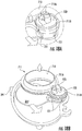
- the cam 720 coupled to the lever arm also rotates, causing the door to open and the retainer member 711 to ride in the cam slots 721, thereby first moving axially upwardly and then ultimately moving the bellows axially downwardly towards the port in the body member 301' as the bellows seal breaks from the door.
- the cam 720 coupled to the lever arm also rotates, causing the door to open and the retainer member 711 to ride in the cam slots 721, thereby first moving axially upwardly and then ultimately moving the bellows axially downwardly towards the port in the body member 301' as the bellows seal breaks from the door.
- the door continues to its fully open position, as shown in FIGS. 19A and 19B , and causes bellows to reach its lowest, valve sealing position (as guided by travel
- both housings include bellows assemblies to isolate their respective valves during connection.
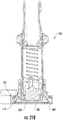
- FIGS. 21A and 21B illustrate the fluid transfer device with the valve members in the closed position, i.e., the door 325' is positioned over the valve port with the bellows 710 against the door 325' .
- the door 325' begins to rotate to the open position.
- the bellows seal retainer member 711 also begins to rotate as the pins ride in the cam slot, and the bellow seal 710 breaks from the door 325'.
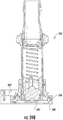
- FIGS. 23A and 23B the door 325' rotates past the bellow seal 710.
- the pins in the seal retainer member 711 continue their travel in the cam slots to lower the bellows seal 710 towards the bottom plate 380' .
- the position of the door 325' and bellows 710 upon completion of the rotation is shown in FIGS. 24A and 25B .
- the door 325' is in the full open position, and the valve port 395' is unobstructed by the door. Similar door movement occurs at the same time in the other member or housing, allowing fluid communication between the two members or housings.
- the bellows 710 seals against the bottom plate 380' of the housing.
- the housings are now locked together, the valve ports open, and the valve members can be engaged by relative axially displacement of one into the other.
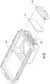
- FIG. 26 illustrates an alternative embodiment where the doors are brought in close proximity to one another in the closed position, thereby reducing or eliminating dead volume between them.
- each door assembly includes a face plate member 910 that includes an opening 911 that may have a gasket 912 fitted about its perimeter.
- the face plate member 910 includes a pair of opposite elongated side track members 913, 914 that extend upwardly from the surface of the face plate member 910.
- each track member 913, 914 includes an intermediate notch 915 which creates a cam for the plug pins 932a-d to push the door flush to the face upon closing and retracting when opening.
- Each track member 913, 914 also includes an end ramp 960 on which two of the plug pins ride when the door cams down to its closed position or up to its open position.
- the notches and ramps cooperate with mating track of cam 624 ( FIG. 25 ), working together to trap the plug pins; one cam 624 bumps the door forward to close, and the mating rail on the cover bumps backward to open.
- each track 913, 914 is positioned slightly inwardly of a side edge of the face plate member 910 so that the region between each track member and the side edge forms, with a respective track member, an L-shaped track for the door assembly to ride on.
- a carrier member 920 is configured to carry plug 930, and includes four upwardly extending side walls 931a-d as shown. Carrier member 920 also includes upwardly extending notched tab 923 which recites slotted shaft 940 as shown in FIG. 26A .
- Plug 930 includes a solid downwardly projecting cylindrical portion 931 that is shaped to seal in opening 911 with the aid of gasket 912.
- handle 945 slides onto the housing and rides in the L-shaped track.
- a slot 946 FIG. 26
- Bellows 947 may enclose shaft 940.
- Actuation of the handle 945 to the closed position translates the plug 931 from the open position to the closed position over the opening 911 in the member 910, as shown in FIG. 26C .
- the plug 931 is now flush to the face of the connector housing, reducing or eliminating dead volume trapped between it and the plug of the other housing member (which is similarly designed).
Claims (8)
- Fluidtransfervorrichtung, umfassend:ein erstes Element (100; 400; 400'), umfassend ein erstes Körperelement (3; 401; 401') mit einem ersten Ventilanschluss (30), einer ersten Tür (2; 425; 425'; 931), die zwischen einer offenen Position des ersten Ventilanschlusses und einer geschlossenen Position des ersten Ventilanschlusses betätigbar ist, und ein erstes Ventilelement (8; 450; 450');ein zweites Element (200; 320; 300'), umfassend ein zweites Körperelement (150; 301; 301') mit einem zweiten Ventilanschluss (23), einer zweiten Tür (22; 325; 325'), die zwischen einer offenen Position des zweiten Ventilanschlusses und einer geschlossenen Position des zweiten Ventilanschlusses betätigbar ist, und ein zweites Ventilelement (110; 350; 350');wobei das erste Element (100; 400; 400') und das zweite Element (200; 320; 300') koppelbar und verschließbar sind, um die erste Tür (2; 425; 425'; 931) in die erste geöffnete Position des Ventilanschlusses und die zweite Tür (22; 325; 325') in die zweite geöffnete Position des Ventilanschlusses zu betätigen, wodurch eine Fließverbindung zwischen dem ersten und dem zweiten Element (100, 200; 400, 320; 400', 300') erzeugt wird;dadurch gekennzeichnet, dassdas erste Element (100; 400; 400') eine erste Tasche für die erste Tür (2; 425; 425'; 931) umfasst, wenn die erste Tür (2; 425; 425'; 931) sich in der ersten geöffneten Position des Ventilanschlusses befindet, und das zweite Element (200; 320; 300') eine zweite Tasche für die zweite Tür (22; 325; 325') umfasst, wenn sich die zweite Tür (22; 325; 325') in der zweiten geöffneten Position des Ventilanschlusses befindet;die erste und zweite Tür (2, 22; 425, 325; 425', 325') zwischen ihren offenen und geschlossenen Positionen in Nockenverbindung stehen;das erste Element (100; 400; 400') und das zweite Element (200; 320; 300') durch relative Drehung des ersten Elements (100; 400; 400') in Bezug auf das zweite Element (200; 320; 300') eingreifbar und verschließbar sind, wobei die relative Drehung bewirkt, dass die erste und die zweite Tür (2, 22; 425, 325; 425', 325') zwischen ihren jeweiligen offenen und geschlossenen Positionen betätigt werden; unddie relative Drehung eine axiale Verschiebung des zweiten Ventilelements (110; 350; 350') in das erste Element (100; 400; 400') bewirkt.
- Fluidtransfervorrichtung nach Anspruch 1, wobei, wenn sich die erste und die zweite Tür (2, 22; 425, 325; 425', 325') in den offenen Positionen befinden, das erste Ventilelement (8; 450; 450') in das zweite Ventilelement (110; 350; 350') verschiebbar ist.
- Fluidtransfervorrichtung nach Anspruch 1, wobei das erste Element eine Entlüftung (625) umfasst.
- Fluidtransfervorrichtung nach Anspruch 1, wobei die erste und die zweite Tür (2, 22; 425, 325; 425', 325') betätigt werden, um sich durch Schwenken zwischen ihrer jeweiligen offenen und geschlossenen Position zu bewegen.
- Verfahren zum Herstellen einer sterilen Verbindung zwischen dem ersten und dem zweiten Ventilelement einer Fluidübertragungsvorrichtung, umfassend:Bereitstellen eines ersten Gehäuses (100; 400; 400'), wobei das erste Gehäuse ein erstes Körperelement (3; 401; 401') mit einem ersten Ventilanschluss (30) und einer ersten Tür (2; 425; 425'; 931) umfasst, die zwischen einer offenen Position des ersten Ventilanschlusses und einer geschlossenen Position des ersten Ventilanschlusses betätigbar ist, und mit dem ersten Ventilelement (8; 450; 450'), wobei das erste Körperelement (3; 401; 401') eine Tasche für die erste Tür (2; 425; 425'; 931) umfasst, wenn sich die erste Tür (2; 425; 425'; 931) in der geöffneten Position des ersten Ventilanschlusses befindet;Bereitstellen eines zweiten Gehäuses (200; 320; 300'), wobei das zweite Gehäuse ein zweites Körperelement (150; 301; 301') mit einem zweiten Ventilanschluss (23) und einer zweiten Tür (22; 325; 325') umfasst, die zwischen einer offenen Position des zweiten Ventilanschlusses und einer geschlossenen Position des zweiten Ventilanschlusses betätigbar ist, und mit dem zweiten Ventilelement (110; 350; 350'), wobei das zweite Körperelement (150; 301; 301') eine Tasche für die zweite Tür (22; 325; 325') umfasst, wenn sich die zweite Tür (22; 325; 325') in der geöffneten Position des zweiten Ventilanschlusses befindet;Koppeln des ersten und des zweiten Gehäuses (100, 200; 400, 320; 400', 300');Verschließen des ersten und des zweiten Gehäuses (100, 200; 400, 320; 400', 300') miteinander, wodurch die erste und die zweite Tür (2, 22; 425, 325; 425', 325') zu den offenen Positionen des jeweiligen Ventilanschlusses betätigt werden;wobei die erste und die zweite Tür (2, 22; 425, 325; 425', 325') durch eine Nockenwirkung betätigt werden;wobei der Schritt des Verriegelns des ersten und des zweiten Gehäuses (100, 200; 400, 320; 400', 300') zusammen durch relative Drehung des ersten Elements (100; 400; 400') in Bezug auf das zweite Element ausgeführt wird (200; 320; 300');wobei die relative Drehung die erste und die zweite Tür (2, 22; 425, 325; 425', 325') zwischen ihren jeweiligen offenen und geschlossenen Positionen betätigt;und wobei die relative Drehung eine axiale Verschiebung des zweiten Ventilelements (110; 350; 350') in das erste Element (100; 400; 400') bewirkt.
- Verfahren nach Anspruch 5, bei dem weiterhin nach dem Verriegelungsschritt das erste Ventilelement (8; 450; 450') in das zweite Ventilelement (110; 350; 350') versetzt wird.
- Verfahren nach Anspruch 6, wobei der Schritt des Versetzens des ersten Ventilelements (8; 450; 450') das Drehen des ersten Ventilelements (8; 450; 450') umfasst.
- Verfahren nach Anspruch 5, wobei die erste und die zweite Tür (2, 22; 425, 325; 425', 325') betätigt werden, um sich durch Schwenken zwischen ihrer jeweiligen offenen und geschlossenen Position zu bewegen.
Priority Applications (1)
| Application Number | Priority Date | Filing Date | Title |
|---|---|---|---|
| EP20162113.3A EP3682939B1 (de) | 2013-03-29 | 2014-03-26 | Sterile verbindung-/lösungskupplung und verfahren |
Applications Claiming Priority (2)
| Application Number | Priority Date | Filing Date | Title |
|---|---|---|---|
| US201361806442P | 2013-03-29 | 2013-03-29 | |
| PCT/US2014/031829 WO2014160756A1 (en) | 2013-03-29 | 2014-03-26 | Sterile connection/disconnection coupling and method |
Related Child Applications (2)
| Application Number | Title | Priority Date | Filing Date |
|---|---|---|---|
| EP20162113.3A Division EP3682939B1 (de) | 2013-03-29 | 2014-03-26 | Sterile verbindung-/lösungskupplung und verfahren |
| EP20162113.3A Division-Into EP3682939B1 (de) | 2013-03-29 | 2014-03-26 | Sterile verbindung-/lösungskupplung und verfahren |
Publications (3)
| Publication Number | Publication Date |
|---|---|
| EP2979014A1 EP2979014A1 (de) | 2016-02-03 |
| EP2979014A4 EP2979014A4 (de) | 2016-11-23 |
| EP2979014B1 true EP2979014B1 (de) | 2020-04-22 |
Family
ID=51625488
Family Applications (2)
| Application Number | Title | Priority Date | Filing Date |
|---|---|---|---|
| EP20162113.3A Active EP3682939B1 (de) | 2013-03-29 | 2014-03-26 | Sterile verbindung-/lösungskupplung und verfahren |
| EP14774870.1A Active EP2979014B1 (de) | 2013-03-29 | 2014-03-26 | Sterile verbindung-/lösungskupplung und verfahren |
Family Applications Before (1)
| Application Number | Title | Priority Date | Filing Date |
|---|---|---|---|
| EP20162113.3A Active EP3682939B1 (de) | 2013-03-29 | 2014-03-26 | Sterile verbindung-/lösungskupplung und verfahren |
Country Status (9)
| Country | Link |
|---|---|
| US (3) | US9901729B2 (de) |
| EP (2) | EP3682939B1 (de) |
| JP (1) | JP6345764B2 (de) |
| KR (1) | KR101769752B1 (de) |
| CN (2) | CN109458465B (de) |
| CA (2) | CA2983222C (de) |
| ES (2) | ES2939536T3 (de) |
| SG (2) | SG10201803735WA (de) |
| WO (1) | WO2014160756A1 (de) |
Families Citing this family (24)
| Publication number | Priority date | Publication date | Assignee | Title |
|---|---|---|---|---|
| US10773863B2 (en) | 2011-06-22 | 2020-09-15 | Sartorius Stedim North America Inc. | Vessel closures and methods for using and manufacturing same |
| CA2983222C (en) | 2013-03-29 | 2019-05-07 | Emd Millipore Corporation | Sterile connection/disconnection coupling and method |
| WO2016172229A1 (en) | 2015-04-20 | 2016-10-27 | Colder Products Company | Single-use aseptic fluid couplings |
| AU2016296495B2 (en) * | 2015-07-17 | 2020-08-13 | Parker-Hannifin Corporation | Sterile fluid connection |
| SG11201802890YA (en) | 2015-10-08 | 2018-05-30 | Colder Prod Co | Reusable aseptic fluid couplings |
| KR20180102141A (ko) | 2016-01-19 | 2018-09-14 | 윌마크 홀딩스, 엘엘씨 | 유체 도관을 탈착 가능하게 연결하기 위한 커넥터 시스템 |
| EP3293524B1 (de) * | 2016-09-12 | 2021-06-09 | Stratec SE | Fluidische kupplung |
| US11319201B2 (en) | 2019-07-23 | 2022-05-03 | Sartorius Stedim North America Inc. | System for simultaneous filling of multiple containers |
| US11577953B2 (en) | 2017-11-14 | 2023-02-14 | Sartorius Stedim North America, Inc. | System for simultaneous distribution of fluid to multiple vessels and method of using the same |
| JP2021503304A (ja) | 2017-11-14 | 2021-02-12 | ザルトリウス ステディム ノース アメリカ インコーポレイテッド | 複数の流体経路を有するジャンクションを有する流体移送組立体 |
| US11691866B2 (en) | 2017-11-14 | 2023-07-04 | Sartorius Stedim North America Inc. | System for simultaneous distribution of fluid to multiple vessels and method of using the same |
| CN108785848B (zh) * | 2018-09-07 | 2023-11-21 | 临沂市兴华医用器材有限公司 | 一种麻醉导管连接器 |
| WO2020124245A1 (en) * | 2018-12-20 | 2020-06-25 | Centre For Commercialization Of Regenerative Medicine | Systems and methods for a reusable, aseptic connector |
| DE102019108664A1 (de) * | 2019-04-03 | 2020-10-08 | Sartorius Stedim Biotech Gmbh | Sterilverbinder für den sterilen Transfer eines flüssigen Mediums |
| US11435019B2 (en) * | 2019-07-25 | 2022-09-06 | Eaton Intelligent Power Limited | Valve guide with integral assembly support |
| US11566736B2 (en) | 2019-12-31 | 2023-01-31 | Colder Products Company | Aseptic fluid couplings |
| US11384883B2 (en) * | 2020-01-31 | 2022-07-12 | General Electric Company | Cryogenic transfer line coupling assembly |
| CN115768512A (zh) | 2020-06-11 | 2023-03-07 | 考尔得产品公司 | 一次性使用断开式流体联接器 |
| WO2022169493A1 (en) * | 2021-02-08 | 2022-08-11 | Colder Products Company | Fluid couplings |
| EP4308213A1 (de) * | 2021-03-19 | 2024-01-24 | Sunflower Therapeutics, PBC | Aseptischer verbinder für fluidleitungen |
| CN117677422A (zh) | 2021-06-17 | 2024-03-08 | 考尔得产品公司 | 无菌液体联接器 |
| WO2023136928A1 (en) * | 2022-01-11 | 2023-07-20 | Emd Millipore Corporation | Sterile fluidic connector with reconnectable connectors and method of aseptic connection |
| WO2023229704A1 (en) * | 2022-05-23 | 2023-11-30 | Colder Products Company | Aseptic fluid couplings |
| GB2620435A (en) * | 2022-07-08 | 2024-01-10 | Watson Marlow Ltd | Aseptic connector |
Family Cites Families (69)
| Publication number | Priority date | Publication date | Assignee | Title |
|---|---|---|---|---|
| US263330A (en) * | 1882-08-29 | Device for controlling and regulating the flow of oil-wells | ||
| US950263A (en) * | 1909-05-26 | 1910-02-22 | Fred H Harpster | Automatic pipe-coupling for cars. |
| US2073048A (en) * | 1936-02-15 | 1937-03-09 | Fred I Clark | Selective volume control valve |
| US2317827A (en) * | 1942-01-09 | 1943-04-27 | Thompson Prod Inc | Quick disconnect coupling |
| US2333496A (en) * | 1942-08-05 | 1943-11-02 | Thompson Prod Inc | Quick disconnect coupling |
| US2399516A (en) * | 1943-10-11 | 1946-04-30 | Thompson Prod Inc | Quick disconnect coupling |
| US2399525A (en) * | 1943-12-04 | 1946-04-30 | Thompson Prod Inc | Quick disconnect coupling |
| US2403620A (en) * | 1943-12-11 | 1946-07-09 | Thompson Prod Inc | Aligning and detent means for quick disconnect couplings |
| US2779608A (en) * | 1952-05-24 | 1957-01-29 | Aeroquip Corp | Combined gate valve and coupling |
| US2757941A (en) * | 1952-06-06 | 1956-08-07 | Aeroquip Corp | Coupling with sliding seal and locking device |
| US2709090A (en) * | 1952-06-25 | 1955-05-24 | Aeroquip Corp | Sliding plate type coupling with slide plate locking pins |
| US2828146A (en) * | 1952-10-08 | 1958-03-25 | Aeroquip Corp | Coupling with sliding seal plates |
| US2687903A (en) * | 1952-12-22 | 1954-08-31 | Aeroquip Corp | Coupling with sliding valves and locking keys |
| US2749146A (en) * | 1953-04-02 | 1956-06-05 | Aeroquip Corp | Coupling with rotary sliding seal |
| US2823887A (en) * | 1955-09-29 | 1958-02-18 | Joseph S Osinski | Hose or pipe coupling with cut-off valve |
| US3106223A (en) * | 1959-02-02 | 1963-10-08 | Apv Co Ltd | Disconnectable coupling |
| US3357452A (en) * | 1965-10-01 | 1967-12-12 | Lockheed Aircraft Corp | Quick-disconnect coupling |
| US3909910A (en) * | 1973-03-29 | 1975-10-07 | Union Carbide Corp | Method of joining the ends of two conduits together in a sterile manner |
| US4022205A (en) * | 1973-11-05 | 1977-05-10 | Tenczar Francis J | Fluid connectors |
| US4019512A (en) * | 1975-12-04 | 1977-04-26 | Tenczar Francis J | Adhesively activated sterile connector |
| US4089506A (en) * | 1977-01-24 | 1978-05-16 | American Hospital Supply Corporation | Gate valve |
| US4306705A (en) * | 1979-01-22 | 1981-12-22 | Svensson Jan A | Slide valve and coupler assembly |
| US4334551A (en) * | 1979-04-30 | 1982-06-15 | Becton Dickinson & Company | Connector |
| US4253684A (en) | 1979-05-14 | 1981-03-03 | Monsanto Company | Quick connect coupler with air shield |
| US4271865A (en) * | 1979-05-14 | 1981-06-09 | Galloway Robert L | Dry break coupling valve |
| US4275763A (en) * | 1979-05-25 | 1981-06-30 | Standard Oil Company (Indiana) | Double-slide valve |
| US4418945A (en) * | 1981-06-08 | 1983-12-06 | International Business Machines Corporation | Sterile connectors |
| IL66276A0 (en) * | 1982-07-08 | 1982-11-30 | Plasson Maagan Michael Ind Ltd | Control device particularly useful as manual slide valve |
| US4509554A (en) * | 1982-11-08 | 1985-04-09 | Failla William G | High and low pressure, quick-disconnect coupling |
| NL8300386A (nl) * | 1983-02-02 | 1984-09-03 | Steritech Bv | Inrichting voor het steriel met elkaar in verbinding stellen van twee kamers. |
| EP0126718A3 (de) * | 1983-05-20 | 1985-10-23 | Bengt Gustavsson | Vorrichtung zur Übertragung einer Substanz aus einem Behälter zu einem anderen Behälter und weiter zur beabsichtigten Anwendung |
| SE449030B (sv) * | 1983-12-19 | 1987-03-30 | Jan Axel Svensson | Flodesreglerande slidventil och kopplingsaggregat |
| IT1218077B (it) * | 1988-06-15 | 1990-04-12 | Dideco Spa | Dispositivo di intercettazione di fluido in una linea |
| US4989638A (en) * | 1989-12-21 | 1991-02-05 | Allied-Signal | Substantially leak-free disconnection apparatus |
| US5092363A (en) * | 1990-01-16 | 1992-03-03 | Ingersoll-Rand Company | Quick and dry coupling |
| US5009252A (en) * | 1990-05-03 | 1991-04-23 | The United States Of America As Represented By The Secretary Of The Army | Air distribution connector valve |
| US5039063A (en) * | 1990-07-13 | 1991-08-13 | Marathon Oil Company | Smooth bore slide valve |
| US5165439A (en) * | 1990-12-14 | 1992-11-24 | Witold Krynicki | Frangible connectors |
| IT1270206B (it) | 1994-06-10 | 1997-04-29 | Faster Srl | Innesto rapido per fluidi sotto pressione |
| DE4443714C2 (de) | 1994-12-09 | 1996-10-17 | Fresenius Ag | Vorrichtung zum Steuern eines Fluidverlaufes |
| US5492147A (en) | 1995-01-17 | 1996-02-20 | Aeroquip Corporation | Dry break coupling |
| US5738143A (en) * | 1996-08-08 | 1998-04-14 | The United States Of America As Represented By The Secretary Of The Army | Butterfly actuated quick coupling connector valve |
| EP1716885A3 (de) | 1997-05-09 | 2006-11-15 | Pall Corporation | Verbindungsanordnungen, Fluidsysteme und Methoden zum Erstellen einer Verbindung |
| US5884648A (en) * | 1997-08-27 | 1999-03-23 | Scholle Corporation | Coupling valve apparatus and method |
| US6077259A (en) | 1998-09-30 | 2000-06-20 | Becton, Dickinson And Company | Contamination resistant connector |
| US6394132B1 (en) * | 1999-11-24 | 2002-05-28 | Richard O. Walcome | Deck wash valve |
| US6679529B2 (en) | 2001-08-06 | 2004-01-20 | Theodore D. Johnson | Connection system |
| US6964406B2 (en) | 2001-08-10 | 2005-11-15 | Alaris Medical Systems, Inc. | Valved male luer |
| US6745998B2 (en) | 2001-08-10 | 2004-06-08 | Alaris Medical Systems, Inc. | Valved male luer |
| US7350535B2 (en) | 2002-04-26 | 2008-04-01 | Gl Tool And Manufacturing Co. Inc. | Valve |
| EP2286870B1 (de) | 2002-04-26 | 2014-09-03 | EMD Millipore Corporation | Dampfsterilisierbares medizinisches Ventil zur einmaligen Verwendung |
| US7137974B2 (en) | 2002-07-26 | 2006-11-21 | Almasian Joseph M | Sterile connector |
| JP4451706B2 (ja) * | 2004-04-28 | 2010-04-14 | 東洋エンジニアリング株式会社 | 配管接続装置 |
| AU2011211445A1 (en) * | 2004-12-10 | 2011-09-01 | Carefusion 303, Inc. | Self-sealing male luer connector with multiple seals |
| US7396051B2 (en) * | 2005-01-14 | 2008-07-08 | Baxa Corporation | Swabable fluid connectors and fluid connector pairs |
| SE527051C2 (sv) | 2005-03-04 | 2005-12-13 | Novaseptic Ab | Metod och anordning för kontaminationstät hopkoppling av ändarna av långsträckta element som slangar eller ledningar |
| US7708025B2 (en) | 2005-03-07 | 2010-05-04 | Colder Products Company | Poppet valve member |
| DE102005020647B4 (de) * | 2005-05-03 | 2013-11-28 | Sartorius Stedim Biotech Gmbh | Verbinder, Verbindersystem und Verfahren zum sterilen Verbinden |
| GB0605531D0 (en) | 2006-03-20 | 2006-04-26 | Powder Systems Ltd | Improvements Relating To Valves |
| SG153002A1 (en) * | 2007-11-16 | 2009-06-29 | Millipore Corp | Fluid transfer device |
| BRPI0909316B1 (pt) | 2008-03-25 | 2021-08-10 | Saint-Gobain Performance Plastics Corporation | Conjunto de conexão e método de formação de conexão estéril |
| DE202009008274U1 (de) | 2009-06-10 | 2009-09-10 | Heinz Meise Gmbh | Vorrichtung zum sterilen Verbinden von medizinischen Einwegartikeln |
| US8671964B2 (en) * | 2010-04-05 | 2014-03-18 | Daniel Py | Aseptic connector with deflectable ring of concern and method |
| FR2958365B1 (fr) * | 2010-04-06 | 2012-05-11 | Millipore Corp | Dispositif de raccordement et systeme de raccordement le comportant |
| CN201916514U (zh) * | 2010-08-13 | 2011-08-03 | 钟国芳 | 单管进水快速热水器陶瓷分水阀 |
| WO2012024624A1 (en) * | 2010-08-20 | 2012-02-23 | Py Daniel C | Connector and related method |
| GB201103068D0 (en) * | 2011-02-22 | 2011-04-06 | The Technology Partnership | Aseptic sampling system |
| CA2983222C (en) | 2013-03-29 | 2019-05-07 | Emd Millipore Corporation | Sterile connection/disconnection coupling and method |
| AU2016296495B2 (en) * | 2015-07-17 | 2020-08-13 | Parker-Hannifin Corporation | Sterile fluid connection |
-
2014
- 2014-03-26 CA CA2983222A patent/CA2983222C/en active Active
- 2014-03-26 WO PCT/US2014/031829 patent/WO2014160756A1/en active Application Filing
- 2014-03-26 SG SG10201803735WA patent/SG10201803735WA/en unknown
- 2014-03-26 EP EP20162113.3A patent/EP3682939B1/de active Active
- 2014-03-26 CN CN201810448671.2A patent/CN109458465B/zh active Active
- 2014-03-26 ES ES20162113T patent/ES2939536T3/es active Active
- 2014-03-26 JP JP2016505544A patent/JP6345764B2/ja active Active
- 2014-03-26 EP EP14774870.1A patent/EP2979014B1/de active Active
- 2014-03-26 SG SG11201507290UA patent/SG11201507290UA/en unknown
- 2014-03-26 US US14/773,426 patent/US9901729B2/en active Active
- 2014-03-26 KR KR1020157029920A patent/KR101769752B1/ko active IP Right Review Request
- 2014-03-26 ES ES14774870T patent/ES2805016T3/es active Active
- 2014-03-26 CN CN201480019424.0A patent/CN105247257B/zh active Active
- 2014-03-26 CA CA2906223A patent/CA2906223C/en active Active
-
2018
- 2018-01-11 US US15/867,915 patent/US10675454B2/en active Active
-
2020
- 2020-06-08 US US16/895,521 patent/US10940307B2/en active Active
Non-Patent Citations (1)
| Title |
|---|
| None * |
Also Published As
| Publication number | Publication date |
|---|---|
| US10940307B2 (en) | 2021-03-09 |
| CN109458465A (zh) | 2019-03-12 |
| EP2979014A4 (de) | 2016-11-23 |
| CA2983222A1 (en) | 2014-10-02 |
| KR20150132534A (ko) | 2015-11-25 |
| CN105247257B (zh) | 2018-05-08 |
| WO2014160756A1 (en) | 2014-10-02 |
| CA2906223A1 (en) | 2014-10-02 |
| ES2805016T3 (es) | 2021-02-10 |
| ES2939536T3 (es) | 2023-04-24 |
| US9901729B2 (en) | 2018-02-27 |
| KR101769752B1 (ko) | 2017-08-21 |
| EP3682939B1 (de) | 2022-12-28 |
| CA2983222C (en) | 2019-05-07 |
| JP2016517936A (ja) | 2016-06-20 |
| SG10201803735WA (en) | 2018-06-28 |
| US20180133453A1 (en) | 2018-05-17 |
| US20160022979A1 (en) | 2016-01-28 |
| CN105247257A (zh) | 2016-01-13 |
| US20200297990A1 (en) | 2020-09-24 |
| CN109458465B (zh) | 2020-03-06 |
| EP2979014A1 (de) | 2016-02-03 |
| EP3682939A1 (de) | 2020-07-22 |
| JP6345764B2 (ja) | 2018-06-20 |
| SG11201507290UA (en) | 2015-10-29 |
| US10675454B2 (en) | 2020-06-09 |
| CA2906223C (en) | 2017-12-05 |
Similar Documents
| Publication | Publication Date | Title |
|---|---|---|
| US10940307B2 (en) | Sterile connection/disconnection coupling and method | |
| US7137974B2 (en) | Sterile connector | |
| EP2060835B1 (de) | Linearventil | |
| EP2678657B1 (de) | Aseptisches probenentnahmesystem | |
| EP2271398B1 (de) | Verbinderanordnung | |
| US9920841B2 (en) | Interface and fluid-transfer system | |
| CN112999508B (zh) | 可再用的无菌流体联接器 | |
| EP2286870B1 (de) | Dampfsterilisierbares medizinisches Ventil zur einmaligen Verwendung | |
| AU2007313359A1 (en) | Valve assembly and system | |
| US7753340B2 (en) | Valve | |
| US20230047183A1 (en) | Cap with dual valve aseptic seals | |
| WO2023136928A1 (en) | Sterile fluidic connector with reconnectable connectors and method of aseptic connection | |
| WO2023172416A1 (en) | Cap with dual valve aseptic seals |
Legal Events
| Date | Code | Title | Description |
|---|---|---|---|
| PUAI | Public reference made under article 153(3) epc to a published international application that has entered the european phase |
Free format text: ORIGINAL CODE: 0009012 |
|
| 17P | Request for examination filed |
Effective date: 20151028 |
|
| AK | Designated contracting states |
Kind code of ref document: A1 Designated state(s): AL AT BE BG CH CY CZ DE DK EE ES FI FR GB GR HR HU IE IS IT LI LT LU LV MC MK MT NL NO PL PT RO RS SE SI SK SM TR |
|
| AX | Request for extension of the european patent |
Extension state: BA ME |
|
| DAX | Request for extension of the european patent (deleted) | ||
| REG | Reference to a national code |
Ref country code: DE Ref legal event code: R079 Ref document number: 602014064165 Country of ref document: DE Free format text: PREVIOUS MAIN CLASS: F16K0003000000 Ipc: A61M0039180000 |
|
| A4 | Supplementary search report drawn up and despatched |
Effective date: 20161026 |
|
| RIC1 | Information provided on ipc code assigned before grant |
Ipc: A61M 39/18 20060101AFI20161020BHEP Ipc: A61M 39/26 20060101ALI20161020BHEP |
|
| STAA | Information on the status of an ep patent application or granted ep patent |
Free format text: STATUS: REQUEST FOR EXAMINATION WAS MADE |
|
| STAA | Information on the status of an ep patent application or granted ep patent |
Free format text: STATUS: EXAMINATION IS IN PROGRESS |
|
| 17Q | First examination report despatched |
Effective date: 20190520 |
|
| GRAP | Despatch of communication of intention to grant a patent |
Free format text: ORIGINAL CODE: EPIDOSNIGR1 |
|
| STAA | Information on the status of an ep patent application or granted ep patent |
Free format text: STATUS: GRANT OF PATENT IS INTENDED |
|
| INTG | Intention to grant announced |
Effective date: 20191029 |
|
| RAP1 | Party data changed (applicant data changed or rights of an application transferred) |
Owner name: EMD MILLIPORE CORPORATION |
|
| GRAS | Grant fee paid |
Free format text: ORIGINAL CODE: EPIDOSNIGR3 |
|
| GRAA | (expected) grant |
Free format text: ORIGINAL CODE: 0009210 |
|
| STAA | Information on the status of an ep patent application or granted ep patent |
Free format text: STATUS: THE PATENT HAS BEEN GRANTED |
|
| RIN1 | Information on inventor provided before grant (corrected) |
Inventor name: LANGLOIS, ROBERT Inventor name: CIECIUCH, JOHN Inventor name: MULDOON, JOSEPH Inventor name: VIGNA, JAMES |
|
| AK | Designated contracting states |
Kind code of ref document: B1 Designated state(s): AL AT BE BG CH CY CZ DE DK EE ES FI FR GB GR HR HU IE IS IT LI LT LU LV MC MK MT NL NO PL PT RO RS SE SI SK SM TR |
|
| REG | Reference to a national code |
Ref country code: CH Ref legal event code: EP |
|
| REG | Reference to a national code |
Ref country code: IE Ref legal event code: FG4D |
|
| REG | Reference to a national code |
Ref country code: DE Ref legal event code: R096 Ref document number: 602014064165 Country of ref document: DE |
|
| REG | Reference to a national code |
Ref country code: AT Ref legal event code: REF Ref document number: 1259281 Country of ref document: AT Kind code of ref document: T Effective date: 20200515 |
|
| REG | Reference to a national code |
Ref country code: CH Ref legal event code: NV Representative=s name: E. BLUM AND CO. AG PATENT- UND MARKENANWAELTE , CH |
|
| REG | Reference to a national code |
Ref country code: NL Ref legal event code: FP |
|
| REG | Reference to a national code |
Ref country code: LT Ref legal event code: MG4D |
|
| PG25 | Lapsed in a contracting state [announced via postgrant information from national office to epo] |
Ref country code: SE Free format text: LAPSE BECAUSE OF FAILURE TO SUBMIT A TRANSLATION OF THE DESCRIPTION OR TO PAY THE FEE WITHIN THE PRESCRIBED TIME-LIMIT Effective date: 20200422 Ref country code: LT Free format text: LAPSE BECAUSE OF FAILURE TO SUBMIT A TRANSLATION OF THE DESCRIPTION OR TO PAY THE FEE WITHIN THE PRESCRIBED TIME-LIMIT Effective date: 20200422 Ref country code: NO Free format text: LAPSE BECAUSE OF FAILURE TO SUBMIT A TRANSLATION OF THE DESCRIPTION OR TO PAY THE FEE WITHIN THE PRESCRIBED TIME-LIMIT Effective date: 20200722 Ref country code: GR Free format text: LAPSE BECAUSE OF FAILURE TO SUBMIT A TRANSLATION OF THE DESCRIPTION OR TO PAY THE FEE WITHIN THE PRESCRIBED TIME-LIMIT Effective date: 20200723 Ref country code: IS Free format text: LAPSE BECAUSE OF FAILURE TO SUBMIT A TRANSLATION OF THE DESCRIPTION OR TO PAY THE FEE WITHIN THE PRESCRIBED TIME-LIMIT Effective date: 20200822 Ref country code: FI Free format text: LAPSE BECAUSE OF FAILURE TO SUBMIT A TRANSLATION OF THE DESCRIPTION OR TO PAY THE FEE WITHIN THE PRESCRIBED TIME-LIMIT Effective date: 20200422 Ref country code: PT Free format text: LAPSE BECAUSE OF FAILURE TO SUBMIT A TRANSLATION OF THE DESCRIPTION OR TO PAY THE FEE WITHIN THE PRESCRIBED TIME-LIMIT Effective date: 20200824 |
|
| REG | Reference to a national code |
Ref country code: AT Ref legal event code: MK05 Ref document number: 1259281 Country of ref document: AT Kind code of ref document: T Effective date: 20200422 |
|
| PG25 | Lapsed in a contracting state [announced via postgrant information from national office to epo] |
Ref country code: LV Free format text: LAPSE BECAUSE OF FAILURE TO SUBMIT A TRANSLATION OF THE DESCRIPTION OR TO PAY THE FEE WITHIN THE PRESCRIBED TIME-LIMIT Effective date: 20200422 Ref country code: HR Free format text: LAPSE BECAUSE OF FAILURE TO SUBMIT A TRANSLATION OF THE DESCRIPTION OR TO PAY THE FEE WITHIN THE PRESCRIBED TIME-LIMIT Effective date: 20200422 Ref country code: BG Free format text: LAPSE BECAUSE OF FAILURE TO SUBMIT A TRANSLATION OF THE DESCRIPTION OR TO PAY THE FEE WITHIN THE PRESCRIBED TIME-LIMIT Effective date: 20200722 Ref country code: RS Free format text: LAPSE BECAUSE OF FAILURE TO SUBMIT A TRANSLATION OF THE DESCRIPTION OR TO PAY THE FEE WITHIN THE PRESCRIBED TIME-LIMIT Effective date: 20200422 |
|
| PG25 | Lapsed in a contracting state [announced via postgrant information from national office to epo] |
Ref country code: AL Free format text: LAPSE BECAUSE OF FAILURE TO SUBMIT A TRANSLATION OF THE DESCRIPTION OR TO PAY THE FEE WITHIN THE PRESCRIBED TIME-LIMIT Effective date: 20200422 |
|
| REG | Reference to a national code |
Ref country code: DE Ref legal event code: R097 Ref document number: 602014064165 Country of ref document: DE |
|
| PG25 | Lapsed in a contracting state [announced via postgrant information from national office to epo] |
Ref country code: RO Free format text: LAPSE BECAUSE OF FAILURE TO SUBMIT A TRANSLATION OF THE DESCRIPTION OR TO PAY THE FEE WITHIN THE PRESCRIBED TIME-LIMIT Effective date: 20200422 Ref country code: CZ Free format text: LAPSE BECAUSE OF FAILURE TO SUBMIT A TRANSLATION OF THE DESCRIPTION OR TO PAY THE FEE WITHIN THE PRESCRIBED TIME-LIMIT Effective date: 20200422 Ref country code: AT Free format text: LAPSE BECAUSE OF FAILURE TO SUBMIT A TRANSLATION OF THE DESCRIPTION OR TO PAY THE FEE WITHIN THE PRESCRIBED TIME-LIMIT Effective date: 20200422 Ref country code: DK Free format text: LAPSE BECAUSE OF FAILURE TO SUBMIT A TRANSLATION OF THE DESCRIPTION OR TO PAY THE FEE WITHIN THE PRESCRIBED TIME-LIMIT Effective date: 20200422 Ref country code: SM Free format text: LAPSE BECAUSE OF FAILURE TO SUBMIT A TRANSLATION OF THE DESCRIPTION OR TO PAY THE FEE WITHIN THE PRESCRIBED TIME-LIMIT Effective date: 20200422 Ref country code: EE Free format text: LAPSE BECAUSE OF FAILURE TO SUBMIT A TRANSLATION OF THE DESCRIPTION OR TO PAY THE FEE WITHIN THE PRESCRIBED TIME-LIMIT Effective date: 20200422 |
|
| REG | Reference to a national code |
Ref country code: ES Ref legal event code: FG2A Ref document number: 2805016 Country of ref document: ES Kind code of ref document: T3 Effective date: 20210210 |
|
| PG25 | Lapsed in a contracting state [announced via postgrant information from national office to epo] |
Ref country code: SK Free format text: LAPSE BECAUSE OF FAILURE TO SUBMIT A TRANSLATION OF THE DESCRIPTION OR TO PAY THE FEE WITHIN THE PRESCRIBED TIME-LIMIT Effective date: 20200422 Ref country code: PL Free format text: LAPSE BECAUSE OF FAILURE TO SUBMIT A TRANSLATION OF THE DESCRIPTION OR TO PAY THE FEE WITHIN THE PRESCRIBED TIME-LIMIT Effective date: 20200422 |
|
| PLBE | No opposition filed within time limit |
Free format text: ORIGINAL CODE: 0009261 |
|
| STAA | Information on the status of an ep patent application or granted ep patent |
Free format text: STATUS: NO OPPOSITION FILED WITHIN TIME LIMIT |
|
| 26N | No opposition filed |
Effective date: 20210125 |
|
| PG25 | Lapsed in a contracting state [announced via postgrant information from national office to epo] |
Ref country code: SI Free format text: LAPSE BECAUSE OF FAILURE TO SUBMIT A TRANSLATION OF THE DESCRIPTION OR TO PAY THE FEE WITHIN THE PRESCRIBED TIME-LIMIT Effective date: 20200422 |
|
| PG25 | Lapsed in a contracting state [announced via postgrant information from national office to epo] |
Ref country code: MC Free format text: LAPSE BECAUSE OF FAILURE TO SUBMIT A TRANSLATION OF THE DESCRIPTION OR TO PAY THE FEE WITHIN THE PRESCRIBED TIME-LIMIT Effective date: 20200422 |
|
| PG25 | Lapsed in a contracting state [announced via postgrant information from national office to epo] |
Ref country code: LU Free format text: LAPSE BECAUSE OF NON-PAYMENT OF DUE FEES Effective date: 20210326 |
|
| PGFP | Annual fee paid to national office [announced via postgrant information from national office to epo] |
Ref country code: NL Payment date: 20230215 Year of fee payment: 10 |
|
| PGFP | Annual fee paid to national office [announced via postgrant information from national office to epo] |
Ref country code: IE Payment date: 20230209 Year of fee payment: 10 Ref country code: FR Payment date: 20230208 Year of fee payment: 10 |
|
| PG25 | Lapsed in a contracting state [announced via postgrant information from national office to epo] |
Ref country code: HU Free format text: LAPSE BECAUSE OF FAILURE TO SUBMIT A TRANSLATION OF THE DESCRIPTION OR TO PAY THE FEE WITHIN THE PRESCRIBED TIME-LIMIT; INVALID AB INITIO Effective date: 20140326 |
|
| PGFP | Annual fee paid to national office [announced via postgrant information from national office to epo] |
Ref country code: IT Payment date: 20230213 Year of fee payment: 10 Ref country code: GB Payment date: 20230202 Year of fee payment: 10 Ref country code: DE Payment date: 20230131 Year of fee payment: 10 Ref country code: BE Payment date: 20230216 Year of fee payment: 10 |
|
| PG25 | Lapsed in a contracting state [announced via postgrant information from national office to epo] |
Ref country code: CY Free format text: LAPSE BECAUSE OF FAILURE TO SUBMIT A TRANSLATION OF THE DESCRIPTION OR TO PAY THE FEE WITHIN THE PRESCRIBED TIME-LIMIT Effective date: 20200422 |
|
| P01 | Opt-out of the competence of the unified patent court (upc) registered |
Effective date: 20230602 |
|
| PGFP | Annual fee paid to national office [announced via postgrant information from national office to epo] |
Ref country code: ES Payment date: 20230404 Year of fee payment: 10 Ref country code: CH Payment date: 20230401 Year of fee payment: 10 |
|
| PGFP | Annual fee paid to national office [announced via postgrant information from national office to epo] |
Ref country code: NL Payment date: 20240108 Year of fee payment: 11 |
|
| PGFP | Annual fee paid to national office [announced via postgrant information from national office to epo] |
Ref country code: IE Payment date: 20240103 Year of fee payment: 11 |