EP2978567B1 - Vliesschleifartikel und verfahren zur herstellung davon - Google Patents
Vliesschleifartikel und verfahren zur herstellung davon Download PDFInfo
- Publication number
- EP2978567B1 EP2978567B1 EP14774036.9A EP14774036A EP2978567B1 EP 2978567 B1 EP2978567 B1 EP 2978567B1 EP 14774036 A EP14774036 A EP 14774036A EP 2978567 B1 EP2978567 B1 EP 2978567B1
- Authority
- EP
- European Patent Office
- Prior art keywords
- abrasive
- abrasive particles
- nonwoven
- outer layer
- fibers
- Prior art date
- Legal status (The legal status is an assumption and is not a legal conclusion. Google has not performed a legal analysis and makes no representation as to the accuracy of the status listed.)
- Active
Links
- 238000000034 method Methods 0.000 title claims description 33
- 239000002245 particle Substances 0.000 claims description 116
- 239000000835 fiber Substances 0.000 claims description 92
- 239000011230 binding agent Substances 0.000 claims description 63
- 239000000203 mixture Substances 0.000 claims description 49
- 239000000463 material Substances 0.000 claims description 34
- 229910052751 metal Inorganic materials 0.000 claims description 31
- 239000002184 metal Substances 0.000 claims description 31
- 235000014113 dietary fatty acids Nutrition 0.000 claims description 17
- 239000000194 fatty acid Substances 0.000 claims description 17
- 229930195729 fatty acid Natural products 0.000 claims description 17
- 150000004665 fatty acids Chemical class 0.000 claims description 17
- 150000003839 salts Chemical class 0.000 claims description 17
- 238000004519 manufacturing process Methods 0.000 claims description 9
- 238000001020 plasma etching Methods 0.000 claims description 7
- 238000012360 testing method Methods 0.000 description 53
- 239000002243 precursor Substances 0.000 description 40
- 238000000576 coating method Methods 0.000 description 23
- 239000011248 coating agent Substances 0.000 description 20
- -1 polyethylene terephthalate Polymers 0.000 description 18
- QIQXTHQIDYTFRH-UHFFFAOYSA-N octadecanoic acid Chemical compound CCCCCCCCCCCCCCCCCC(O)=O QIQXTHQIDYTFRH-UHFFFAOYSA-N 0.000 description 16
- 229920005989 resin Polymers 0.000 description 16
- 239000011347 resin Substances 0.000 description 16
- 239000000126 substance Substances 0.000 description 16
- XLYOFNOQVPJJNP-UHFFFAOYSA-N water Substances O XLYOFNOQVPJJNP-UHFFFAOYSA-N 0.000 description 16
- 239000002002 slurry Substances 0.000 description 15
- 230000000052 comparative effect Effects 0.000 description 14
- 239000007789 gas Substances 0.000 description 12
- 230000008569 process Effects 0.000 description 10
- 239000003082 abrasive agent Substances 0.000 description 8
- 229920003229 poly(methyl methacrylate) Polymers 0.000 description 8
- 239000004926 polymethyl methacrylate Substances 0.000 description 8
- TWNQGVIAIRXVLR-UHFFFAOYSA-N oxo(oxoalumanyloxy)alumane Chemical compound O=[Al]O[Al]=O TWNQGVIAIRXVLR-UHFFFAOYSA-N 0.000 description 7
- 229920001568 phenolic resin Polymers 0.000 description 7
- 239000005011 phenolic resin Substances 0.000 description 7
- 238000005507 spraying Methods 0.000 description 7
- UKMSUNONTOPOIO-UHFFFAOYSA-N docosanoic acid Chemical compound CCCCCCCCCCCCCCCCCCCCCC(O)=O UKMSUNONTOPOIO-UHFFFAOYSA-N 0.000 description 6
- POULHZVOKOAJMA-UHFFFAOYSA-N dodecanoic acid Chemical compound CCCCCCCCCCCC(O)=O POULHZVOKOAJMA-UHFFFAOYSA-N 0.000 description 6
- 238000000227 grinding Methods 0.000 description 6
- IPCSVZSSVZVIGE-UHFFFAOYSA-N hexadecanoic acid Chemical compound CCCCCCCCCCCCCCCC(O)=O IPCSVZSSVZVIGE-UHFFFAOYSA-N 0.000 description 6
- UTOPWMOLSKOLTQ-UHFFFAOYSA-N octacosanoic acid Chemical compound CCCCCCCCCCCCCCCCCCCCCCCCCCCC(O)=O UTOPWMOLSKOLTQ-UHFFFAOYSA-N 0.000 description 6
- QYSGYZVSCZSLHT-UHFFFAOYSA-N octafluoropropane Chemical compound FC(F)(F)C(F)(F)C(F)(F)F QYSGYZVSCZSLHT-UHFFFAOYSA-N 0.000 description 6
- 238000001878 scanning electron micrograph Methods 0.000 description 6
- 229920001187 thermosetting polymer Polymers 0.000 description 6
- 239000007788 liquid Substances 0.000 description 5
- 239000000314 lubricant Substances 0.000 description 5
- 238000009832 plasma treatment Methods 0.000 description 5
- 101000682328 Bacillus subtilis (strain 168) 50S ribosomal protein L18 Proteins 0.000 description 4
- DBMJMQXJHONAFJ-UHFFFAOYSA-M Sodium laurylsulphate Chemical compound [Na+].CCCCCCCCCCCCOS([O-])(=O)=O DBMJMQXJHONAFJ-UHFFFAOYSA-M 0.000 description 4
- 239000000654 additive Substances 0.000 description 4
- PNEYBMLMFCGWSK-UHFFFAOYSA-N aluminium oxide Inorganic materials [O-2].[O-2].[O-2].[Al+3].[Al+3] PNEYBMLMFCGWSK-UHFFFAOYSA-N 0.000 description 4
- 230000008901 benefit Effects 0.000 description 4
- CJZGTCYPCWQAJB-UHFFFAOYSA-L calcium stearate Chemical compound [Ca+2].CCCCCCCCCCCCCCCCCC([O-])=O.CCCCCCCCCCCCCCCCCC([O-])=O CJZGTCYPCWQAJB-UHFFFAOYSA-L 0.000 description 4
- 239000008116 calcium stearate Substances 0.000 description 4
- 235000013539 calcium stearate Nutrition 0.000 description 4
- 239000000919 ceramic Substances 0.000 description 4
- GHVNFZFCNZKVNT-UHFFFAOYSA-N decanoic acid Chemical compound CCCCCCCCCC(O)=O GHVNFZFCNZKVNT-UHFFFAOYSA-N 0.000 description 4
- 239000000975 dye Substances 0.000 description 4
- 230000000694 effects Effects 0.000 description 4
- 229920001971 elastomer Polymers 0.000 description 4
- 239000000049 pigment Substances 0.000 description 4
- 229920000647 polyepoxide Polymers 0.000 description 4
- 235000019333 sodium laurylsulphate Nutrition 0.000 description 4
- RYYKJJJTJZKILX-UHFFFAOYSA-M sodium octadecanoate Chemical compound [Na+].CCCCCCCCCCCCCCCCCC([O-])=O RYYKJJJTJZKILX-UHFFFAOYSA-M 0.000 description 4
- 239000007921 spray Substances 0.000 description 4
- KUBDPQJOLOUJRM-UHFFFAOYSA-N 2-(chloromethyl)oxirane;4-[2-(4-hydroxyphenyl)propan-2-yl]phenol Chemical compound ClCC1CO1.C=1C=C(O)C=CC=1C(C)(C)C1=CC=C(O)C=C1 KUBDPQJOLOUJRM-UHFFFAOYSA-N 0.000 description 3
- 235000021357 Behenic acid Nutrition 0.000 description 3
- OYPRJOBELJOOCE-UHFFFAOYSA-N Calcium Chemical compound [Ca] OYPRJOBELJOOCE-UHFFFAOYSA-N 0.000 description 3
- 239000005639 Lauric acid Substances 0.000 description 3
- 229920000877 Melamine resin Polymers 0.000 description 3
- 229920003091 Methocel™ Polymers 0.000 description 3
- 235000021314 Palmitic acid Nutrition 0.000 description 3
- 235000021355 Stearic acid Nutrition 0.000 description 3
- 229920001807 Urea-formaldehyde Polymers 0.000 description 3
- 239000002518 antifoaming agent Substances 0.000 description 3
- 229940116226 behenic acid Drugs 0.000 description 3
- 239000011575 calcium Substances 0.000 description 3
- 229910052791 calcium Inorganic materials 0.000 description 3
- 239000003990 capacitor Substances 0.000 description 3
- 125000004432 carbon atom Chemical group C* 0.000 description 3
- 230000008859 change Effects 0.000 description 3
- 239000003795 chemical substances by application Substances 0.000 description 3
- 229920001577 copolymer Polymers 0.000 description 3
- 230000008878 coupling Effects 0.000 description 3
- 238000010168 coupling process Methods 0.000 description 3
- 238000005859 coupling reaction Methods 0.000 description 3
- 229910001610 cryolite Inorganic materials 0.000 description 3
- 239000000806 elastomer Substances 0.000 description 3
- 239000000839 emulsion Substances 0.000 description 3
- 239000003822 epoxy resin Substances 0.000 description 3
- 239000000945 filler Substances 0.000 description 3
- LNEPOXFFQSENCJ-UHFFFAOYSA-N haloperidol Chemical compound C1CC(O)(C=2C=CC(Cl)=CC=2)CCN1CCCC(=O)C1=CC=C(F)C=C1 LNEPOXFFQSENCJ-UHFFFAOYSA-N 0.000 description 3
- 238000010438 heat treatment Methods 0.000 description 3
- HGPXWXLYXNVULB-UHFFFAOYSA-M lithium stearate Chemical compound [Li+].CCCCCCCCCCCCCCCCCC([O-])=O HGPXWXLYXNVULB-UHFFFAOYSA-M 0.000 description 3
- 150000002739 metals Chemical class 0.000 description 3
- WQEPLUUGTLDZJY-UHFFFAOYSA-N n-Pentadecanoic acid Natural products CCCCCCCCCCCCCCC(O)=O WQEPLUUGTLDZJY-UHFFFAOYSA-N 0.000 description 3
- OQCDKBAXFALNLD-UHFFFAOYSA-N octadecanoic acid Natural products CCCCCCCC(C)CCCCCCCCC(O)=O OQCDKBAXFALNLD-UHFFFAOYSA-N 0.000 description 3
- 229920003023 plastic Polymers 0.000 description 3
- 239000004033 plastic Substances 0.000 description 3
- 239000004014 plasticizer Substances 0.000 description 3
- 229920000642 polymer Polymers 0.000 description 3
- 238000012545 processing Methods 0.000 description 3
- 230000005855 radiation Effects 0.000 description 3
- 239000007787 solid Substances 0.000 description 3
- 239000008117 stearic acid Substances 0.000 description 3
- 239000004094 surface-active agent Substances 0.000 description 3
- 229920002994 synthetic fiber Polymers 0.000 description 3
- 239000012209 synthetic fiber Substances 0.000 description 3
- 238000010998 test method Methods 0.000 description 3
- TUNFSRHWOTWDNC-HKGQFRNVSA-N tetradecanoic acid Chemical compound CCCCCCCCCCCCC[14C](O)=O TUNFSRHWOTWDNC-HKGQFRNVSA-N 0.000 description 3
- FRPZMMHWLSIFAZ-UHFFFAOYSA-N 10-undecenoic acid Chemical compound OC(=O)CCCCCCCCC=C FRPZMMHWLSIFAZ-UHFFFAOYSA-N 0.000 description 2
- 239000004925 Acrylic resin Substances 0.000 description 2
- 229920000178 Acrylic resin Polymers 0.000 description 2
- 239000005632 Capric acid (CAS 334-48-5) Substances 0.000 description 2
- MYMOFIZGZYHOMD-UHFFFAOYSA-N Dioxygen Chemical compound O=O MYMOFIZGZYHOMD-UHFFFAOYSA-N 0.000 description 2
- JOYRKODLDBILNP-UHFFFAOYSA-N Ethyl urethane Chemical compound CCOC(N)=O JOYRKODLDBILNP-UHFFFAOYSA-N 0.000 description 2
- XEEYBQQBJWHFJM-UHFFFAOYSA-N Iron Chemical compound [Fe] XEEYBQQBJWHFJM-UHFFFAOYSA-N 0.000 description 2
- 229920005929 JONCRYL® 89 Polymers 0.000 description 2
- WHXSMMKQMYFTQS-UHFFFAOYSA-N Lithium Chemical compound [Li] WHXSMMKQMYFTQS-UHFFFAOYSA-N 0.000 description 2
- TWRXJAOTZQYOKJ-UHFFFAOYSA-L Magnesium chloride Chemical compound [Mg+2].[Cl-].[Cl-] TWRXJAOTZQYOKJ-UHFFFAOYSA-L 0.000 description 2
- 229920001730 Moisture cure polyurethane Polymers 0.000 description 2
- 229920002292 Nylon 6 Polymers 0.000 description 2
- 239000004952 Polyamide Substances 0.000 description 2
- 239000004698 Polyethylene Substances 0.000 description 2
- 239000004743 Polypropylene Substances 0.000 description 2
- ZLMJMSJWJFRBEC-UHFFFAOYSA-N Potassium Chemical compound [K] ZLMJMSJWJFRBEC-UHFFFAOYSA-N 0.000 description 2
- WCUXLLCKKVVCTQ-UHFFFAOYSA-M Potassium chloride Chemical compound [Cl-].[K+] WCUXLLCKKVVCTQ-UHFFFAOYSA-M 0.000 description 2
- VYPSYNLAJGMNEJ-UHFFFAOYSA-N Silicium dioxide Chemical compound O=[Si]=O VYPSYNLAJGMNEJ-UHFFFAOYSA-N 0.000 description 2
- FAPWRFPIFSIZLT-UHFFFAOYSA-M Sodium chloride Chemical compound [Na+].[Cl-] FAPWRFPIFSIZLT-UHFFFAOYSA-M 0.000 description 2
- HCHKCACWOHOZIP-UHFFFAOYSA-N Zinc Chemical compound [Zn] HCHKCACWOHOZIP-UHFFFAOYSA-N 0.000 description 2
- MCMNRKCIXSYSNV-UHFFFAOYSA-N Zirconium dioxide Chemical compound O=[Zr]=O MCMNRKCIXSYSNV-UHFFFAOYSA-N 0.000 description 2
- NIXOWILDQLNWCW-UHFFFAOYSA-M acrylate group Chemical class C(C=C)(=O)[O-] NIXOWILDQLNWCW-UHFFFAOYSA-M 0.000 description 2
- NIXOWILDQLNWCW-UHFFFAOYSA-N acrylic acid group Chemical group C(C=C)(=O)O NIXOWILDQLNWCW-UHFFFAOYSA-N 0.000 description 2
- DTOSIQBPPRVQHS-PDBXOOCHSA-N alpha-linolenic acid Chemical compound CC\C=C/C\C=C/C\C=C/CCCCCCCC(O)=O DTOSIQBPPRVQHS-PDBXOOCHSA-N 0.000 description 2
- 229910052782 aluminium Inorganic materials 0.000 description 2
- 239000002216 antistatic agent Substances 0.000 description 2
- YZXBAPSDXZZRGB-DOFZRALJSA-N arachidonic acid Chemical compound CCCCC\C=C/C\C=C/C\C=C/C\C=C/CCCC(O)=O YZXBAPSDXZZRGB-DOFZRALJSA-N 0.000 description 2
- QVGXLLKOCUKJST-UHFFFAOYSA-N atomic oxygen Chemical compound [O] QVGXLLKOCUKJST-UHFFFAOYSA-N 0.000 description 2
- 229910052788 barium Inorganic materials 0.000 description 2
- DSAJWYNOEDNPEQ-UHFFFAOYSA-N barium atom Chemical compound [Ba] DSAJWYNOEDNPEQ-UHFFFAOYSA-N 0.000 description 2
- 230000005540 biological transmission Effects 0.000 description 2
- IISBACLAFKSPIT-UHFFFAOYSA-N bisphenol A Chemical compound C=1C=C(O)C=CC=1C(C)(C)C1=CC=C(O)C=C1 IISBACLAFKSPIT-UHFFFAOYSA-N 0.000 description 2
- 230000000903 blocking effect Effects 0.000 description 2
- KHAVLLBUVKBTBG-UHFFFAOYSA-N caproleic acid Natural products OC(=O)CCCCCCCC=C KHAVLLBUVKBTBG-UHFFFAOYSA-N 0.000 description 2
- 239000003054 catalyst Substances 0.000 description 2
- 229920006217 cellulose acetate butyrate Polymers 0.000 description 2
- 239000004927 clay Substances 0.000 description 2
- 239000003086 colorant Substances 0.000 description 2
- 239000002131 composite material Substances 0.000 description 2
- 150000001875 compounds Chemical class 0.000 description 2
- 239000007822 coupling agent Substances 0.000 description 2
- 229910003460 diamond Inorganic materials 0.000 description 2
- 239000010432 diamond Substances 0.000 description 2
- 239000006185 dispersion Substances 0.000 description 2
- VKOBVWXKNCXXDE-UHFFFAOYSA-N icosanoic acid Chemical compound CCCCCCCCCCCCCCCCCCCC(O)=O VKOBVWXKNCXXDE-UHFFFAOYSA-N 0.000 description 2
- 229910052500 inorganic mineral Inorganic materials 0.000 description 2
- 229910052744 lithium Inorganic materials 0.000 description 2
- 229910001092 metal group alloy Inorganic materials 0.000 description 2
- 235000010755 mineral Nutrition 0.000 description 2
- 239000011707 mineral Substances 0.000 description 2
- 239000000178 monomer Substances 0.000 description 2
- SNICXCGAKADSCV-UHFFFAOYSA-N nicotine Chemical compound CN1CCCC1C1=CC=CN=C1 SNICXCGAKADSCV-UHFFFAOYSA-N 0.000 description 2
- 239000002736 nonionic surfactant Substances 0.000 description 2
- 229920003986 novolac Polymers 0.000 description 2
- WWZKQHOCKIZLMA-UHFFFAOYSA-N octanoic acid Chemical compound CCCCCCCC(O)=O WWZKQHOCKIZLMA-UHFFFAOYSA-N 0.000 description 2
- 229910052760 oxygen Inorganic materials 0.000 description 2
- 239000001301 oxygen Substances 0.000 description 2
- 229920000058 polyacrylate Polymers 0.000 description 2
- 229920002647 polyamide Polymers 0.000 description 2
- 229920000728 polyester Polymers 0.000 description 2
- 229920000573 polyethylene Polymers 0.000 description 2
- 239000004848 polyfunctional curative Substances 0.000 description 2
- 238000006116 polymerization reaction Methods 0.000 description 2
- 229920001155 polypropylene Polymers 0.000 description 2
- 229920005553 polystyrene-acrylate Polymers 0.000 description 2
- 239000004800 polyvinyl chloride Substances 0.000 description 2
- 239000011591 potassium Substances 0.000 description 2
- 229910052700 potassium Inorganic materials 0.000 description 2
- 229920003987 resole Polymers 0.000 description 2
- HBMJWWWQQXIZIP-UHFFFAOYSA-N silicon carbide Chemical compound [Si+]#[C-] HBMJWWWQQXIZIP-UHFFFAOYSA-N 0.000 description 2
- 229910010271 silicon carbide Inorganic materials 0.000 description 2
- 239000002904 solvent Substances 0.000 description 2
- 229920001169 thermoplastic Polymers 0.000 description 2
- 239000004634 thermosetting polymer Substances 0.000 description 2
- 229960002703 undecylenic acid Drugs 0.000 description 2
- 150000003673 urethanes Chemical class 0.000 description 2
- 239000001993 wax Substances 0.000 description 2
- 239000002023 wood Substances 0.000 description 2
- 229910052725 zinc Inorganic materials 0.000 description 2
- 239000011701 zinc Substances 0.000 description 2
- OYHQOLUKZRVURQ-NTGFUMLPSA-N (9Z,12Z)-9,10,12,13-tetratritiooctadeca-9,12-dienoic acid Chemical compound C(CCCCCCC\C(=C(/C\C(=C(/CCCCC)\[3H])\[3H])\[3H])\[3H])(=O)O OYHQOLUKZRVURQ-NTGFUMLPSA-N 0.000 description 1
- WRIDQFICGBMAFQ-UHFFFAOYSA-N (E)-8-Octadecenoic acid Natural products CCCCCCCCCC=CCCCCCCC(O)=O WRIDQFICGBMAFQ-UHFFFAOYSA-N 0.000 description 1
- HBAIZGPCSAAFSU-UHFFFAOYSA-N 1-(2-hydroxyethyl)imidazolidin-2-one Chemical compound OCCN1CCNC1=O HBAIZGPCSAAFSU-UHFFFAOYSA-N 0.000 description 1
- ARXJGSRGQADJSQ-UHFFFAOYSA-N 1-methoxypropan-2-ol Chemical compound COCC(C)O ARXJGSRGQADJSQ-UHFFFAOYSA-N 0.000 description 1
- ADCWDMYESTYBBN-UHFFFAOYSA-N 2-[n-(2-hydroxyethyl)-3-methyl-4-[(4-nitrophenyl)diazenyl]anilino]ethanol Chemical compound CC1=CC(N(CCO)CCO)=CC=C1N=NC1=CC=C([N+]([O-])=O)C=C1 ADCWDMYESTYBBN-UHFFFAOYSA-N 0.000 description 1
- KXGFMDJXCMQABM-UHFFFAOYSA-N 2-methoxy-6-methylphenol Chemical compound [CH]OC1=CC=CC([CH])=C1O KXGFMDJXCMQABM-UHFFFAOYSA-N 0.000 description 1
- LQJBNNIYVWPHFW-UHFFFAOYSA-N 20:1omega9c fatty acid Natural products CCCCCCCCCCC=CCCCCCCCC(O)=O LQJBNNIYVWPHFW-UHFFFAOYSA-N 0.000 description 1
- WXBXVVIUZANZAU-UHFFFAOYSA-N 2E-decenoic acid Natural products CCCCCCCC=CC(O)=O WXBXVVIUZANZAU-UHFFFAOYSA-N 0.000 description 1
- QSBYPNXLFMSGKH-UHFFFAOYSA-N 9-Heptadecensaeure Natural products CCCCCCCC=CCCCCCCCC(O)=O QSBYPNXLFMSGKH-UHFFFAOYSA-N 0.000 description 1
- QGZKDVFQNNGYKY-UHFFFAOYSA-O Ammonium Chemical compound [NH4+] QGZKDVFQNNGYKY-UHFFFAOYSA-O 0.000 description 1
- QYEXBYZXHDUPRC-UHFFFAOYSA-N B#[Ti]#B Chemical compound B#[Ti]#B QYEXBYZXHDUPRC-UHFFFAOYSA-N 0.000 description 1
- 229910052580 B4C Inorganic materials 0.000 description 1
- 229910052582 BN Inorganic materials 0.000 description 1
- 229920001342 Bakelite® Polymers 0.000 description 1
- PZNSFCLAULLKQX-UHFFFAOYSA-N Boron nitride Chemical compound N#B PZNSFCLAULLKQX-UHFFFAOYSA-N 0.000 description 1
- DPUOLQHDNGRHBS-UHFFFAOYSA-N Brassidinsaeure Natural products CCCCCCCCC=CCCCCCCCCCCCC(O)=O DPUOLQHDNGRHBS-UHFFFAOYSA-N 0.000 description 1
- 244000025254 Cannabis sativa Species 0.000 description 1
- 235000012766 Cannabis sativa ssp. sativa var. sativa Nutrition 0.000 description 1
- 235000012765 Cannabis sativa ssp. sativa var. spontanea Nutrition 0.000 description 1
- 239000005635 Caprylic acid (CAS 124-07-2) Substances 0.000 description 1
- OKTJSMMVPCPJKN-UHFFFAOYSA-N Carbon Chemical compound [C] OKTJSMMVPCPJKN-UHFFFAOYSA-N 0.000 description 1
- 240000000491 Corchorus aestuans Species 0.000 description 1
- 235000011777 Corchorus aestuans Nutrition 0.000 description 1
- 235000010862 Corchorus capsularis Nutrition 0.000 description 1
- 229920000742 Cotton Polymers 0.000 description 1
- 239000004971 Cross linker Substances 0.000 description 1
- 229920003261 Durez Polymers 0.000 description 1
- 239000004593 Epoxy Substances 0.000 description 1
- URXZXNYJPAJJOQ-UHFFFAOYSA-N Erucic acid Natural products CCCCCCC=CCCCCCCCCCCCC(O)=O URXZXNYJPAJJOQ-UHFFFAOYSA-N 0.000 description 1
- 239000001856 Ethyl cellulose Substances 0.000 description 1
- ZZSNKZQZMQGXPY-UHFFFAOYSA-N Ethyl cellulose Chemical compound CCOCC1OC(OC)C(OCC)C(OCC)C1OC1C(O)C(O)C(OC)C(CO)O1 ZZSNKZQZMQGXPY-UHFFFAOYSA-N 0.000 description 1
- 244000043261 Hevea brasiliensis Species 0.000 description 1
- DGAQECJNVWCQMB-PUAWFVPOSA-M Ilexoside XXIX Chemical compound C[C@@H]1CC[C@@]2(CC[C@@]3(C(=CC[C@H]4[C@]3(CC[C@@H]5[C@@]4(CC[C@@H](C5(C)C)OS(=O)(=O)[O-])C)C)[C@@H]2[C@]1(C)O)C)C(=O)O[C@H]6[C@@H]([C@H]([C@@H]([C@H](O6)CO)O)O)O.[Na+] DGAQECJNVWCQMB-PUAWFVPOSA-M 0.000 description 1
- 235000021353 Lignoceric acid Nutrition 0.000 description 1
- CQXMAMUUWHYSIY-UHFFFAOYSA-N Lignoceric acid Natural products CCCCCCCCCCCCCCCCCCCCCCCC(=O)OCCC1=CC=C(O)C=C1 CQXMAMUUWHYSIY-UHFFFAOYSA-N 0.000 description 1
- FYYHWMGAXLPEAU-UHFFFAOYSA-N Magnesium Chemical compound [Mg] FYYHWMGAXLPEAU-UHFFFAOYSA-N 0.000 description 1
- 239000004677 Nylon Substances 0.000 description 1
- 229920002302 Nylon 6,6 Polymers 0.000 description 1
- CTQNGGLPUBDAKN-UHFFFAOYSA-N O-Xylene Chemical compound CC1=CC=CC=C1C CTQNGGLPUBDAKN-UHFFFAOYSA-N 0.000 description 1
- 239000005642 Oleic acid Substances 0.000 description 1
- ZQPPMHVWECSIRJ-UHFFFAOYSA-N Oleic acid Natural products CCCCCCCCC=CCCCCCCCC(O)=O ZQPPMHVWECSIRJ-UHFFFAOYSA-N 0.000 description 1
- 239000004697 Polyetherimide Substances 0.000 description 1
- 239000004793 Polystyrene Substances 0.000 description 1
- 239000004820 Pressure-sensitive adhesive Substances 0.000 description 1
- 229920000297 Rayon Polymers 0.000 description 1
- 229920003265 Resimene® Polymers 0.000 description 1
- BQCADISMDOOEFD-UHFFFAOYSA-N Silver Chemical compound [Ag] BQCADISMDOOEFD-UHFFFAOYSA-N 0.000 description 1
- NINIDFKCEFEMDL-UHFFFAOYSA-N Sulfur Chemical compound [S] NINIDFKCEFEMDL-UHFFFAOYSA-N 0.000 description 1
- 229910033181 TiB2 Inorganic materials 0.000 description 1
- ATJFFYVFTNAWJD-UHFFFAOYSA-N Tin Chemical compound [Sn] ATJFFYVFTNAWJD-UHFFFAOYSA-N 0.000 description 1
- RTAQQCXQSZGOHL-UHFFFAOYSA-N Titanium Chemical compound [Ti] RTAQQCXQSZGOHL-UHFFFAOYSA-N 0.000 description 1
- 235000021322 Vaccenic acid Nutrition 0.000 description 1
- UWHZIFQPPBDJPM-FPLPWBNLSA-M Vaccenic acid Natural products CCCCCC\C=C/CCCCCCCCCC([O-])=O UWHZIFQPPBDJPM-FPLPWBNLSA-M 0.000 description 1
- XTXRWKRVRITETP-UHFFFAOYSA-N Vinyl acetate Chemical compound CC(=O)OC=C XTXRWKRVRITETP-UHFFFAOYSA-N 0.000 description 1
- QYKIQEUNHZKYBP-UHFFFAOYSA-N Vinyl ether Chemical class C=COC=C QYKIQEUNHZKYBP-UHFFFAOYSA-N 0.000 description 1
- 238000005299 abrasion Methods 0.000 description 1
- XECAHXYUAAWDEL-UHFFFAOYSA-N acrylonitrile butadiene styrene Chemical compound C=CC=C.C=CC#N.C=CC1=CC=CC=C1 XECAHXYUAAWDEL-UHFFFAOYSA-N 0.000 description 1
- 239000004676 acrylonitrile butadiene styrene Substances 0.000 description 1
- 229920000122 acrylonitrile butadiene styrene Polymers 0.000 description 1
- 230000009471 action Effects 0.000 description 1
- 125000001931 aliphatic group Chemical group 0.000 description 1
- 229920013820 alkyl cellulose Polymers 0.000 description 1
- 229910045601 alloy Inorganic materials 0.000 description 1
- 239000000956 alloy Substances 0.000 description 1
- 235000020661 alpha-linolenic acid Nutrition 0.000 description 1
- XAGFODPZIPBFFR-UHFFFAOYSA-N aluminium Chemical compound [Al] XAGFODPZIPBFFR-UHFFFAOYSA-N 0.000 description 1
- 229920003180 amino resin Polymers 0.000 description 1
- 150000003863 ammonium salts Chemical class 0.000 description 1
- 230000000844 anti-bacterial effect Effects 0.000 description 1
- 229910052787 antimony Inorganic materials 0.000 description 1
- WATWJIUSRGPENY-UHFFFAOYSA-N antimony atom Chemical compound [Sb] WATWJIUSRGPENY-UHFFFAOYSA-N 0.000 description 1
- 229940114079 arachidonic acid Drugs 0.000 description 1
- 235000021342 arachidonic acid Nutrition 0.000 description 1
- 150000004982 aromatic amines Chemical class 0.000 description 1
- 239000003899 bactericide agent Substances 0.000 description 1
- 239000004637 bakelite Substances 0.000 description 1
- AGXUVMPSUKZYDT-UHFFFAOYSA-L barium(2+);octadecanoate Chemical compound [Ba+2].CCCCCCCCCCCCCCCCCC([O-])=O.CCCCCCCCCCCCCCCCCC([O-])=O AGXUVMPSUKZYDT-UHFFFAOYSA-L 0.000 description 1
- 230000002902 bimodal effect Effects 0.000 description 1
- 229910052797 bismuth Inorganic materials 0.000 description 1
- JCXGWMGPZLAOME-UHFFFAOYSA-N bismuth atom Chemical compound [Bi] JCXGWMGPZLAOME-UHFFFAOYSA-N 0.000 description 1
- 229920001400 block copolymer Polymers 0.000 description 1
- 238000007664 blowing Methods 0.000 description 1
- INAHAJYZKVIDIZ-UHFFFAOYSA-N boron carbide Chemical compound B12B3B4C32B41 INAHAJYZKVIDIZ-UHFFFAOYSA-N 0.000 description 1
- 229910052793 cadmium Inorganic materials 0.000 description 1
- BDOSMKKIYDKNTQ-UHFFFAOYSA-N cadmium atom Chemical compound [Cd] BDOSMKKIYDKNTQ-UHFFFAOYSA-N 0.000 description 1
- 235000009120 camo Nutrition 0.000 description 1
- 239000006229 carbon black Substances 0.000 description 1
- 125000002915 carbonyl group Chemical group [*:2]C([*:1])=O 0.000 description 1
- 125000003178 carboxy group Chemical group [H]OC(*)=O 0.000 description 1
- 150000001735 carboxylic acids Chemical class 0.000 description 1
- 229920002301 cellulose acetate Polymers 0.000 description 1
- 229920003086 cellulose ether Polymers 0.000 description 1
- 239000012461 cellulose resin Substances 0.000 description 1
- CETPSERCERDGAM-UHFFFAOYSA-N ceric oxide Chemical compound O=[Ce]=O CETPSERCERDGAM-UHFFFAOYSA-N 0.000 description 1
- 229910000422 cerium(IV) oxide Inorganic materials 0.000 description 1
- 235000005607 chanvre indien Nutrition 0.000 description 1
- 238000004140 cleaning Methods 0.000 description 1
- 229910017052 cobalt Inorganic materials 0.000 description 1
- 239000010941 cobalt Substances 0.000 description 1
- GUTLYIVDDKVIGB-UHFFFAOYSA-N cobalt atom Chemical compound [Co] GUTLYIVDDKVIGB-UHFFFAOYSA-N 0.000 description 1
- 238000004040 coloring Methods 0.000 description 1
- 239000011246 composite particle Substances 0.000 description 1
- 230000006835 compression Effects 0.000 description 1
- 238000007906 compression Methods 0.000 description 1
- 238000009833 condensation Methods 0.000 description 1
- 230000005494 condensation Effects 0.000 description 1
- 238000010276 construction Methods 0.000 description 1
- 238000007796 conventional method Methods 0.000 description 1
- 238000001816 cooling Methods 0.000 description 1
- 238000007766 curtain coating Methods 0.000 description 1
- 239000002173 cutting fluid Substances 0.000 description 1
- 238000005520 cutting process Methods 0.000 description 1
- 230000007423 decrease Effects 0.000 description 1
- 230000008021 deposition Effects 0.000 description 1
- 238000007607 die coating method Methods 0.000 description 1
- GYZLOYUZLJXAJU-UHFFFAOYSA-N diglycidyl ether Chemical compound C1OC1COCC1CO1 GYZLOYUZLJXAJU-UHFFFAOYSA-N 0.000 description 1
- 229910001882 dioxygen Inorganic materials 0.000 description 1
- AOMZHDJXSYHPKS-UHFFFAOYSA-L disodium 4-amino-5-hydroxy-3-[(4-nitrophenyl)diazenyl]-6-phenyldiazenylnaphthalene-2,7-disulfonate Chemical compound [Na+].[Na+].[O-]S(=O)(=O)C1=CC2=CC(S([O-])(=O)=O)=C(N=NC=3C=CC=CC=3)C(O)=C2C(N)=C1N=NC1=CC=C([N+]([O-])=O)C=C1 AOMZHDJXSYHPKS-UHFFFAOYSA-L 0.000 description 1
- 238000009826 distribution Methods 0.000 description 1
- 230000005670 electromagnetic radiation Effects 0.000 description 1
- 125000003700 epoxy group Chemical group 0.000 description 1
- 230000003628 erosive effect Effects 0.000 description 1
- DPUOLQHDNGRHBS-KTKRTIGZSA-N erucic acid Chemical compound CCCCCCCC\C=C/CCCCCCCCCCCC(O)=O DPUOLQHDNGRHBS-KTKRTIGZSA-N 0.000 description 1
- 238000005530 etching Methods 0.000 description 1
- FARYTWBWLZAXNK-WAYWQWQTSA-N ethyl (z)-3-(methylamino)but-2-enoate Chemical compound CCOC(=O)\C=C(\C)NC FARYTWBWLZAXNK-WAYWQWQTSA-N 0.000 description 1
- 235000010944 ethyl methyl cellulose Nutrition 0.000 description 1
- 230000008020 evaporation Effects 0.000 description 1
- 238000001704 evaporation Methods 0.000 description 1
- 238000001125 extrusion Methods 0.000 description 1
- 239000002657 fibrous material Substances 0.000 description 1
- NBVXSUQYWXRMNV-UHFFFAOYSA-N fluoromethane Chemical compound FC NBVXSUQYWXRMNV-UHFFFAOYSA-N 0.000 description 1
- 239000006260 foam Substances 0.000 description 1
- 239000000417 fungicide Substances 0.000 description 1
- 239000002223 garnet Substances 0.000 description 1
- 239000011521 glass Substances 0.000 description 1
- 239000003292 glue Substances 0.000 description 1
- 239000010439 graphite Substances 0.000 description 1
- 229910002804 graphite Inorganic materials 0.000 description 1
- 150000004820 halides Chemical class 0.000 description 1
- 239000011487 hemp Substances 0.000 description 1
- 238000007373 indentation Methods 0.000 description 1
- 230000006698 induction Effects 0.000 description 1
- 239000004615 ingredient Substances 0.000 description 1
- 230000002401 inhibitory effect Effects 0.000 description 1
- 239000003999 initiator Substances 0.000 description 1
- 230000000977 initiatory effect Effects 0.000 description 1
- 239000011147 inorganic material Substances 0.000 description 1
- 239000010954 inorganic particle Substances 0.000 description 1
- 229910052742 iron Inorganic materials 0.000 description 1
- JEIPFZHSYJVQDO-UHFFFAOYSA-N iron(III) oxide Inorganic materials O=[Fe]O[Fe]=O JEIPFZHSYJVQDO-UHFFFAOYSA-N 0.000 description 1
- 239000012948 isocyanate Chemical class 0.000 description 1
- 150000002513 isocyanates Chemical class 0.000 description 1
- ZFSLODLOARCGLH-UHFFFAOYSA-N isocyanuric acid Chemical class OC1=NC(O)=NC(O)=N1 ZFSLODLOARCGLH-UHFFFAOYSA-N 0.000 description 1
- QXJSBBXBKPUZAA-UHFFFAOYSA-N isooleic acid Natural products CCCCCCCC=CCCCCCCCCC(O)=O QXJSBBXBKPUZAA-UHFFFAOYSA-N 0.000 description 1
- 229940094522 laponite Drugs 0.000 description 1
- 230000000670 limiting effect Effects 0.000 description 1
- 229960004488 linolenic acid Drugs 0.000 description 1
- XCOBTUNSZUJCDH-UHFFFAOYSA-B lithium magnesium sodium silicate Chemical compound [Li+].[Li+].[OH-].[OH-].[OH-].[OH-].[OH-].[OH-].[OH-].[OH-].[OH-].[OH-].[OH-].[OH-].[Na+].[Na+].[Mg+2].[Mg+2].[Mg+2].[Mg+2].[Mg+2].[Mg+2].[Mg+2].[Mg+2].[Mg+2].[Mg+2].[Mg+2].[Mg+2].[Mg+2].[Mg+2].[Mg+2].[Mg+2].O1[Si](O2)([O-])O[Si]3([O-])O[Si]1([O-])O[Si]2([O-])O3.O1[Si](O2)([O-])O[Si]3([O-])O[Si]1([O-])O[Si]2([O-])O3.O1[Si](O2)([O-])O[Si]3([O-])O[Si]1([O-])O[Si]2([O-])O3.O1[Si](O2)([O-])O[Si]3([O-])O[Si]1([O-])O[Si]2([O-])O3.O1[Si](O2)([O-])O[Si]3([O-])O[Si]1([O-])O[Si]2([O-])O3.O1[Si](O2)([O-])O[Si]3([O-])O[Si]1([O-])O[Si]2([O-])O3 XCOBTUNSZUJCDH-UHFFFAOYSA-B 0.000 description 1
- 239000011777 magnesium Substances 0.000 description 1
- 229910052749 magnesium Inorganic materials 0.000 description 1
- 229910001629 magnesium chloride Inorganic materials 0.000 description 1
- 125000005395 methacrylic acid group Chemical group 0.000 description 1
- 229920000609 methyl cellulose Polymers 0.000 description 1
- 239000001923 methylcellulose Substances 0.000 description 1
- 235000010981 methylcellulose Nutrition 0.000 description 1
- 229920003087 methylethyl cellulose Polymers 0.000 description 1
- 238000001000 micrograph Methods 0.000 description 1
- 238000002156 mixing Methods 0.000 description 1
- 238000012986 modification Methods 0.000 description 1
- 230000004048 modification Effects 0.000 description 1
- CWQXQMHSOZUFJS-UHFFFAOYSA-N molybdenum disulfide Chemical compound S=[Mo]=S CWQXQMHSOZUFJS-UHFFFAOYSA-N 0.000 description 1
- 229910052982 molybdenum disulfide Inorganic materials 0.000 description 1
- 229920003052 natural elastomer Polymers 0.000 description 1
- 229920001194 natural rubber Polymers 0.000 description 1
- 229920001778 nylon Polymers 0.000 description 1
- 229960002446 octanoic acid Drugs 0.000 description 1
- 239000003921 oil Substances 0.000 description 1
- ZQPPMHVWECSIRJ-KTKRTIGZSA-N oleic acid Chemical compound CCCCCCCC\C=C/CCCCCCCC(O)=O ZQPPMHVWECSIRJ-KTKRTIGZSA-N 0.000 description 1
- 239000011368 organic material Substances 0.000 description 1
- 239000011146 organic particle Substances 0.000 description 1
- 239000003960 organic solvent Substances 0.000 description 1
- 150000002898 organic sulfur compounds Chemical class 0.000 description 1
- 238000012856 packing Methods 0.000 description 1
- 230000036961 partial effect Effects 0.000 description 1
- 239000011236 particulate material Substances 0.000 description 1
- PMJHHCWVYXUKFD-UHFFFAOYSA-N penta-1,3-diene Chemical compound CC=CC=C PMJHHCWVYXUKFD-UHFFFAOYSA-N 0.000 description 1
- 229960004065 perflutren Drugs 0.000 description 1
- 230000002093 peripheral effect Effects 0.000 description 1
- ISWSIDIOOBJBQZ-UHFFFAOYSA-N phenol group Chemical group C1(=CC=CC=C1)O ISWSIDIOOBJBQZ-UHFFFAOYSA-N 0.000 description 1
- 239000011941 photocatalyst Substances 0.000 description 1
- 238000005498 polishing Methods 0.000 description 1
- 229920001084 poly(chloroprene) Polymers 0.000 description 1
- 229920002492 poly(sulfone) Polymers 0.000 description 1
- 229920002239 polyacrylonitrile Polymers 0.000 description 1
- 229920002857 polybutadiene Polymers 0.000 description 1
- 229920001748 polybutylene Polymers 0.000 description 1
- 239000004417 polycarbonate Substances 0.000 description 1
- 229920000515 polycarbonate Polymers 0.000 description 1
- 229920001601 polyetherimide Polymers 0.000 description 1
- 229920000139 polyethylene terephthalate Polymers 0.000 description 1
- 239000005020 polyethylene terephthalate Substances 0.000 description 1
- 229920000098 polyolefin Polymers 0.000 description 1
- 229920006324 polyoxymethylene Polymers 0.000 description 1
- 229920002223 polystyrene Polymers 0.000 description 1
- 229920002635 polyurethane Polymers 0.000 description 1
- 239000004814 polyurethane Substances 0.000 description 1
- 229920003225 polyurethane elastomer Polymers 0.000 description 1
- 229920000915 polyvinyl chloride Polymers 0.000 description 1
- 229920000131 polyvinylidene Polymers 0.000 description 1
- 239000001103 potassium chloride Substances 0.000 description 1
- 235000011164 potassium chloride Nutrition 0.000 description 1
- LLHKCFNBLRBOGN-UHFFFAOYSA-N propylene glycol methyl ether acetate Chemical compound COCC(C)OC(C)=O LLHKCFNBLRBOGN-UHFFFAOYSA-N 0.000 description 1
- 239000002964 rayon Substances 0.000 description 1
- 239000001044 red dye Substances 0.000 description 1
- 239000001054 red pigment Substances 0.000 description 1
- 239000002990 reinforced plastic Substances 0.000 description 1
- 239000005060 rubber Substances 0.000 description 1
- NNNVXFKZMRGJPM-KHPPLWFESA-N sapienic acid Chemical compound CCCCCCCCC\C=C/CCCCC(O)=O NNNVXFKZMRGJPM-KHPPLWFESA-N 0.000 description 1
- 235000003441 saturated fatty acids Nutrition 0.000 description 1
- 150000004671 saturated fatty acids Chemical class 0.000 description 1
- 150000003333 secondary alcohols Chemical class 0.000 description 1
- 239000000377 silicon dioxide Substances 0.000 description 1
- ABTOQLMXBSRXSM-UHFFFAOYSA-N silicon tetrafluoride Chemical class F[Si](F)(F)F ABTOQLMXBSRXSM-UHFFFAOYSA-N 0.000 description 1
- 229910052709 silver Inorganic materials 0.000 description 1
- 239000004332 silver Substances 0.000 description 1
- 239000000344 soap Substances 0.000 description 1
- 239000011734 sodium Substances 0.000 description 1
- 229910052708 sodium Inorganic materials 0.000 description 1
- 239000011780 sodium chloride Substances 0.000 description 1
- FVEFRICMTUKAML-UHFFFAOYSA-M sodium tetradecyl sulfate Chemical compound [Na+].CCCCC(CC)CCC(CC(C)C)OS([O-])(=O)=O FVEFRICMTUKAML-UHFFFAOYSA-M 0.000 description 1
- 229910001495 sodium tetrafluoroborate Inorganic materials 0.000 description 1
- 238000007655 standard test method Methods 0.000 description 1
- 239000004575 stone Substances 0.000 description 1
- 239000011145 styrene acrylonitrile resin Substances 0.000 description 1
- 229920003048 styrene butadiene rubber Polymers 0.000 description 1
- 150000004763 sulfides Chemical class 0.000 description 1
- 239000011593 sulfur Substances 0.000 description 1
- 229910052717 sulfur Inorganic materials 0.000 description 1
- 230000003746 surface roughness Effects 0.000 description 1
- 239000000375 suspending agent Substances 0.000 description 1
- 230000002459 sustained effect Effects 0.000 description 1
- 239000008399 tap water Substances 0.000 description 1
- 235000020679 tap water Nutrition 0.000 description 1
- 239000004753 textile Substances 0.000 description 1
- 239000012815 thermoplastic material Substances 0.000 description 1
- 229920002803 thermoplastic polyurethane Polymers 0.000 description 1
- 239000002562 thickening agent Substances 0.000 description 1
- 229910052719 titanium Inorganic materials 0.000 description 1
- 239000010936 titanium Substances 0.000 description 1
- WXBXVVIUZANZAU-CMDGGOBGSA-N trans-2-decenoic acid Chemical compound CCCCCCC\C=C\C(O)=O WXBXVVIUZANZAU-CMDGGOBGSA-N 0.000 description 1
- UWHZIFQPPBDJPM-BQYQJAHWSA-N trans-vaccenic acid Chemical compound CCCCCC\C=C\CCCCCCCCCC(O)=O UWHZIFQPPBDJPM-BQYQJAHWSA-N 0.000 description 1
- 235000021122 unsaturated fatty acids Nutrition 0.000 description 1
- 150000004670 unsaturated fatty acids Chemical class 0.000 description 1
- 239000002699 waste material Substances 0.000 description 1
- 238000009736 wetting Methods 0.000 description 1
- 239000000080 wetting agent Substances 0.000 description 1
- 210000002268 wool Anatomy 0.000 description 1
- 239000008096 xylene Substances 0.000 description 1
- XOOUIPVCVHRTMJ-UHFFFAOYSA-L zinc stearate Chemical compound [Zn+2].CCCCCCCCCCCCCCCCCC([O-])=O.CCCCCCCCCCCCCCCCCC([O-])=O XOOUIPVCVHRTMJ-UHFFFAOYSA-L 0.000 description 1
Images


Classifications
-
- B—PERFORMING OPERATIONS; TRANSPORTING
- B24—GRINDING; POLISHING
- B24D—TOOLS FOR GRINDING, BUFFING OR SHARPENING
- B24D3/00—Physical features of abrasive bodies, or sheets, e.g. abrasive surfaces of special nature; Abrasive bodies or sheets characterised by their constituents
- B24D3/02—Physical features of abrasive bodies, or sheets, e.g. abrasive surfaces of special nature; Abrasive bodies or sheets characterised by their constituents the constituent being used as bonding agent
- B24D3/20—Physical features of abrasive bodies, or sheets, e.g. abrasive surfaces of special nature; Abrasive bodies or sheets characterised by their constituents the constituent being used as bonding agent and being essentially organic
- B24D3/28—Resins or natural or synthetic macromolecular compounds
- B24D3/32—Resins or natural or synthetic macromolecular compounds for porous or cellular structure
-
- B—PERFORMING OPERATIONS; TRANSPORTING
- B24—GRINDING; POLISHING
- B24D—TOOLS FOR GRINDING, BUFFING OR SHARPENING
- B24D11/00—Constructional features of flexible abrasive materials; Special features in the manufacture of such materials
- B24D11/001—Manufacture of flexible abrasive materials
-
- B—PERFORMING OPERATIONS; TRANSPORTING
- B24—GRINDING; POLISHING
- B24D—TOOLS FOR GRINDING, BUFFING OR SHARPENING
- B24D18/00—Manufacture of grinding tools or other grinding devices, e.g. wheels, not otherwise provided for
- B24D18/0027—Manufacture of grinding tools or other grinding devices, e.g. wheels, not otherwise provided for by impregnation
-
- B—PERFORMING OPERATIONS; TRANSPORTING
- B24—GRINDING; POLISHING
- B24D—TOOLS FOR GRINDING, BUFFING OR SHARPENING
- B24D3/00—Physical features of abrasive bodies, or sheets, e.g. abrasive surfaces of special nature; Abrasive bodies or sheets characterised by their constituents
- B24D3/34—Physical features of abrasive bodies, or sheets, e.g. abrasive surfaces of special nature; Abrasive bodies or sheets characterised by their constituents characterised by additives enhancing special physical properties, e.g. wear resistance, electric conductivity, self-cleaning properties
- B24D3/346—Physical features of abrasive bodies, or sheets, e.g. abrasive surfaces of special nature; Abrasive bodies or sheets characterised by their constituents characterised by additives enhancing special physical properties, e.g. wear resistance, electric conductivity, self-cleaning properties utilised during polishing, or grinding operation
-
- F—MECHANICAL ENGINEERING; LIGHTING; HEATING; WEAPONS; BLASTING
- F02—COMBUSTION ENGINES; HOT-GAS OR COMBUSTION-PRODUCT ENGINE PLANTS
- F02B—INTERNAL-COMBUSTION PISTON ENGINES; COMBUSTION ENGINES IN GENERAL
- F02B29/00—Engines characterised by provision for charging or scavenging not provided for in groups F02B25/00, F02B27/00 or F02B33/00 - F02B39/00; Details thereof
- F02B29/04—Cooling of air intake supply
- F02B29/0406—Layout of the intake air cooling or coolant circuit
- F02B29/0418—Layout of the intake air cooling or coolant circuit the intake air cooler having a bypass or multiple flow paths within the heat exchanger to vary the effective heat transfer surface
-
- F—MECHANICAL ENGINEERING; LIGHTING; HEATING; WEAPONS; BLASTING
- F02—COMBUSTION ENGINES; HOT-GAS OR COMBUSTION-PRODUCT ENGINE PLANTS
- F02B—INTERNAL-COMBUSTION PISTON ENGINES; COMBUSTION ENGINES IN GENERAL
- F02B37/00—Engines characterised by provision of pumps driven at least for part of the time by exhaust
- F02B37/12—Control of the pumps
- F02B37/16—Control of the pumps by bypassing charging air
-
- F—MECHANICAL ENGINEERING; LIGHTING; HEATING; WEAPONS; BLASTING
- F02—COMBUSTION ENGINES; HOT-GAS OR COMBUSTION-PRODUCT ENGINE PLANTS
- F02D—CONTROLLING COMBUSTION ENGINES
- F02D19/00—Controlling engines characterised by their use of non-liquid fuels, pluralities of fuels, or non-fuel substances added to the combustible mixtures
- F02D19/02—Controlling engines characterised by their use of non-liquid fuels, pluralities of fuels, or non-fuel substances added to the combustible mixtures peculiar to engines working with gaseous fuels
- F02D19/021—Control of components of the fuel supply system
- F02D19/023—Control of components of the fuel supply system to adjust the fuel mass or volume flow
-
- F—MECHANICAL ENGINEERING; LIGHTING; HEATING; WEAPONS; BLASTING
- F02—COMBUSTION ENGINES; HOT-GAS OR COMBUSTION-PRODUCT ENGINE PLANTS
- F02D—CONTROLLING COMBUSTION ENGINES
- F02D19/00—Controlling engines characterised by their use of non-liquid fuels, pluralities of fuels, or non-fuel substances added to the combustible mixtures
- F02D19/06—Controlling engines characterised by their use of non-liquid fuels, pluralities of fuels, or non-fuel substances added to the combustible mixtures peculiar to engines working with pluralities of fuels, e.g. alternatively with light and heavy fuel oil, other than engines indifferent to the fuel consumed
- F02D19/08—Controlling engines characterised by their use of non-liquid fuels, pluralities of fuels, or non-fuel substances added to the combustible mixtures peculiar to engines working with pluralities of fuels, e.g. alternatively with light and heavy fuel oil, other than engines indifferent to the fuel consumed simultaneously using pluralities of fuels
- F02D19/10—Controlling engines characterised by their use of non-liquid fuels, pluralities of fuels, or non-fuel substances added to the combustible mixtures peculiar to engines working with pluralities of fuels, e.g. alternatively with light and heavy fuel oil, other than engines indifferent to the fuel consumed simultaneously using pluralities of fuels peculiar to compression-ignition engines in which the main fuel is gaseous
- F02D19/105—Controlling engines characterised by their use of non-liquid fuels, pluralities of fuels, or non-fuel substances added to the combustible mixtures peculiar to engines working with pluralities of fuels, e.g. alternatively with light and heavy fuel oil, other than engines indifferent to the fuel consumed simultaneously using pluralities of fuels peculiar to compression-ignition engines in which the main fuel is gaseous operating in a special mode, e.g. in a liquid fuel only mode for starting
-
- F—MECHANICAL ENGINEERING; LIGHTING; HEATING; WEAPONS; BLASTING
- F02—COMBUSTION ENGINES; HOT-GAS OR COMBUSTION-PRODUCT ENGINE PLANTS
- F02D—CONTROLLING COMBUSTION ENGINES
- F02D41/00—Electrical control of supply of combustible mixture or its constituents
- F02D41/0025—Controlling engines characterised by use of non-liquid fuels, pluralities of fuels, or non-fuel substances added to the combustible mixtures
- F02D41/0027—Controlling engines characterised by use of non-liquid fuels, pluralities of fuels, or non-fuel substances added to the combustible mixtures the fuel being gaseous
-
- F—MECHANICAL ENGINEERING; LIGHTING; HEATING; WEAPONS; BLASTING
- F02—COMBUSTION ENGINES; HOT-GAS OR COMBUSTION-PRODUCT ENGINE PLANTS
- F02M—SUPPLYING COMBUSTION ENGINES IN GENERAL WITH COMBUSTIBLE MIXTURES OR CONSTITUENTS THEREOF
- F02M21/00—Apparatus for supplying engines with non-liquid fuels, e.g. gaseous fuels stored in liquid form
- F02M21/02—Apparatus for supplying engines with non-liquid fuels, e.g. gaseous fuels stored in liquid form for gaseous fuels
- F02M21/04—Gas-air mixing apparatus
- F02M21/047—Venturi mixer
-
- F—MECHANICAL ENGINEERING; LIGHTING; HEATING; WEAPONS; BLASTING
- F02—COMBUSTION ENGINES; HOT-GAS OR COMBUSTION-PRODUCT ENGINE PLANTS
- F02M—SUPPLYING COMBUSTION ENGINES IN GENERAL WITH COMBUSTIBLE MIXTURES OR CONSTITUENTS THEREOF
- F02M26/00—Engine-pertinent apparatus for adding exhaust gases to combustion-air, main fuel or fuel-air mixture, e.g. by exhaust gas recirculation [EGR] systems
- F02M26/02—EGR systems specially adapted for supercharged engines
- F02M26/04—EGR systems specially adapted for supercharged engines with a single turbocharger
-
- F—MECHANICAL ENGINEERING; LIGHTING; HEATING; WEAPONS; BLASTING
- F02—COMBUSTION ENGINES; HOT-GAS OR COMBUSTION-PRODUCT ENGINE PLANTS
- F02M—SUPPLYING COMBUSTION ENGINES IN GENERAL WITH COMBUSTIBLE MIXTURES OR CONSTITUENTS THEREOF
- F02M43/00—Fuel-injection apparatus operating simultaneously on two or more fuels, or on a liquid fuel and another liquid, e.g. the other liquid being an anti-knock additive
-
- F—MECHANICAL ENGINEERING; LIGHTING; HEATING; WEAPONS; BLASTING
- F02—COMBUSTION ENGINES; HOT-GAS OR COMBUSTION-PRODUCT ENGINE PLANTS
- F02D—CONTROLLING COMBUSTION ENGINES
- F02D41/00—Electrical control of supply of combustible mixture or its constituents
- F02D41/02—Circuit arrangements for generating control signals
- F02D41/14—Introducing closed-loop corrections
- F02D41/1401—Introducing closed-loop corrections characterised by the control or regulation method
- F02D2041/1433—Introducing closed-loop corrections characterised by the control or regulation method using a model or simulation of the system
- F02D2041/1434—Inverse model
-
- F—MECHANICAL ENGINEERING; LIGHTING; HEATING; WEAPONS; BLASTING
- F02—COMBUSTION ENGINES; HOT-GAS OR COMBUSTION-PRODUCT ENGINE PLANTS
- F02D—CONTROLLING COMBUSTION ENGINES
- F02D2200/00—Input parameters for engine control
- F02D2200/02—Input parameters for engine control the parameters being related to the engine
- F02D2200/04—Engine intake system parameters
- F02D2200/0402—Engine intake system parameters the parameter being determined by using a model of the engine intake or its components
-
- Y—GENERAL TAGGING OF NEW TECHNOLOGICAL DEVELOPMENTS; GENERAL TAGGING OF CROSS-SECTIONAL TECHNOLOGIES SPANNING OVER SEVERAL SECTIONS OF THE IPC; TECHNICAL SUBJECTS COVERED BY FORMER USPC CROSS-REFERENCE ART COLLECTIONS [XRACs] AND DIGESTS
- Y02—TECHNOLOGIES OR APPLICATIONS FOR MITIGATION OR ADAPTATION AGAINST CLIMATE CHANGE
- Y02T—CLIMATE CHANGE MITIGATION TECHNOLOGIES RELATED TO TRANSPORTATION
- Y02T10/00—Road transport of goods or passengers
- Y02T10/10—Internal combustion engine [ICE] based vehicles
- Y02T10/12—Improving ICE efficiencies
-
- Y—GENERAL TAGGING OF NEW TECHNOLOGICAL DEVELOPMENTS; GENERAL TAGGING OF CROSS-SECTIONAL TECHNOLOGIES SPANNING OVER SEVERAL SECTIONS OF THE IPC; TECHNICAL SUBJECTS COVERED BY FORMER USPC CROSS-REFERENCE ART COLLECTIONS [XRACs] AND DIGESTS
- Y02—TECHNOLOGIES OR APPLICATIONS FOR MITIGATION OR ADAPTATION AGAINST CLIMATE CHANGE
- Y02T—CLIMATE CHANGE MITIGATION TECHNOLOGIES RELATED TO TRANSPORTATION
- Y02T10/00—Road transport of goods or passengers
- Y02T10/10—Internal combustion engine [ICE] based vehicles
- Y02T10/30—Use of alternative fuels, e.g. biofuels
Definitions
- the present disclosure relates broadly to nonwoven abrasive articles and methods of making them.
- Nonwoven abrasive articles comprising a three-dimensional fiber web bonded at contact points between adjacent fibers are used extensively in the manufacture of abrasive articles for cleaning, abrading, finishing and polishing applications on any of a variety of surfaces.
- the nonwoven abrasive articles generally include abrasive particles and a binder material (commonly termed a "binder") that bonds the fibers within the nonwoven web to each other and secures the abrasive particles to the nonwoven web.
- nonwoven abrasive includes a lofty open fiber web.
- Exemplary of such nonwoven abrasive articles are those described in U.S. Patent No. 2,958,593 (Hoover et al. ).
- Exemplary commercial nonwoven abrasive articles include nonwoven abrasive hand pads such as those marketed by 3M Company of Saint Paul, Minnesota under the trade designation SCOTCH-BRITE.
- nonwoven abrasive articles include convolute abrasive wheels and unitized abrasive wheels.
- Nonwoven abrasive wheels typically have abrasive particles distributed through the layers of nonwoven web bonded together with a binder that bonds layers of nonwoven webs together, and likewise bonds the abrasive particles to the nonwoven web.
- Unitized abrasive wheels have individual discs of nonwoven web arranged in a parallel fashion to form a cylinder having a hollow axial core.
- convolute abrasive wheels have a nonwoven web that is spirally wound about and affixed to a core member.
- WO 97/ 42003 discloses a nonwoven abrasive article according to the preamble of claim 1 and a corresponding method for making a nonwoven article according to the preamble of claim 5.
- WO 99/ 56914 discloses a method of making a nonwoven abrasive article, the method comprising:
- the present inventors have discovered that application of an overlayer composition comprising a metal stearate to nonwoven abrasive articles having abrasive particles that are not deeply submerged within the binder material improves abrading performance, while in cases where the abrasive particles that are deeply submerged, addition of the same overlayer composition results in degraded abrading performance.
- nonwoven abrasive article according to claim 1 and the methods for making a nonwoven abrasive article according to claims 5 and 8 solve the aforementioned drawbacks.
- the term "closely packed” in reference to abrasive particles means that substantially all of the abrasive particles are within a distance (between outer surfaces) of one average particle diameter to the nearest abrasive particle, but does not necessarily mean that the abrasive particles are in the closest theoretically possible packing arrangement.
- the term "recognizable outline" in reference to an abrasive particle means that the peripheral outline of the abrasive particle as viewed from at least one direction is discernible at a magnification of 150 times (i.e., 150x) by a human eye having 20/20 vision.
- the abrasive particles are not substantially submerged in a mass of binder material, although they may have a thin (e.g., substantially uniform) coating of binder covering them if it conforms to the shapes of the abrasive particles.
- the FRICTION TEST is as follows: Test specimens of nonwoven abrasive members and polymethyl methacrylate discs to be used in this test procedure are equilibrated for at least 24 hours at 17 percent relative humidity and 25 °C prior to use.
- a standard testing surface is prepared by attaching a 4-inch (10.2 cm) diameter by 1/8-inch (3.2-mm) thick polymethyl methacrylate (PMMA) disc, M Ball hardness 90-105 onto a horizontal test stage such that it cannot move relative to the stage during the test.
- PMMA polymethyl methacrylate
- a 2 inches x 2 inches (5 cm x 5 cm) area test specimen is cut from a nonwoven abrasive member to be tested and affixed to a 2 inches x 2 inches (5 cm x 5 cm) 500-gram metal weight using double-sided pressure-sensitive adhesive tape, assuring that the 2 inches x 2 inches area of the test specimen is adjacent to the metal weight.
- the weighted test specimen is placed, with a working surface (i.e., a surface of the nonwoven abrasive member intended to abrade a workpiece) in contact with the PMMA disc, on the test surface and attached to the load cell of a friction testing machine (e.g., a Thwing-Albert Friction/Peel Tester Model 225-100 from Thwing-Albert Instrument Company, West Berlin, New Jersey or a functional equivalent) at 17 percent relative humidity and 25 °C. Horizontal force is applied by the friction testing machine at a horizontal stage translational speed of 31 cm/minute and the kinetic coefficient of friction is determined as the average kinetic coefficient of friction over a 5-second intervals.
- a friction testing machine e.g., a Thwing-Albert Friction/Peel Tester Model 225-100 from Thwing-Albert Instrument Company, West Berlin, New Jersey or a functional equivalent
- Horizontal force is applied by the friction testing machine at a horizontal stage translational speed of 31 cm/minute
- FIG. 24 shows an exemplary configuration for carrying out the FRICTION TEST described above.
- PMMA disc 2420 is attached to horizontal test stage 2450.
- the nonwoven abrasive member test specimen 2410 is placed upon PMMA disc 2420 and metal weight 2400 is secured with double-sided tape 2415 to test specimen 2410.
- Horizontal rod 2430 is attached to the friction testing device load cell 2460 and metal weight 2400. Force is applied along direction 2470 by the friction testing machine during the test.
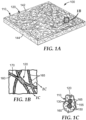
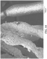
- exemplary nonwoven abrasive article 100 comprises nonwoven abrasive member 110.
- the nonwoven abrasive member 110 comprises lofty open fiber web 120 comprising fibers 130 bonded to one another.
- Nonwoven abrasive member 110 has first and second opposed working surfaces 142, 144.
- Abrasive particles 150 are adhered to fibers 130 by binder material 155.
- abrasive particles 150 adjacent to working surfaces 142, 144 form a visible outer layer 165 of abrasive particles 150 along fibers 130.
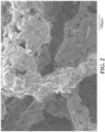
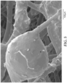
- Abrasive particles 150 in visible outer layer 165 are closely packed and have recognizable outlines 170 (see also FIG. 10 ).
- Overlayer composition 160 comprises a fatty acid metal salt, and is disposed on at least a portion of binder material 155 and abrasive particles 150 adjacent to working surfaces 142 and 144 of nonwoven abrasive member 110.
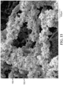
- the percentage of abrasive particles in the visible outer layer may be at least 80 percent, at least 85 percent, at least 90 percent, at least 95 percent, at least 97 percent, or 99 percent, or even 100 percent.
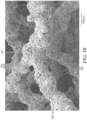
- crevices are disposed between adjacent abrasive particles in the visible outer layer.
- crevices 180 are disposed between adjacent abrasive particles 150.
- At least one of working surfaces 142, 144 has a kinetic coefficient of friction which may be at least 0.54 according to the FRICTION TEST described herein.
- the lofty open fiber web is a lofty nonwoven fibrous material having a substantially continuous network of voids extending therethrough.
- lofty open fiber web By use of the term "lofty open fiber web”, what is intended is a layer of nonwoven web material composed of a plurality of randomly oriented fibers, typically entangled, having a substantially continuous network of interconnecting voids extending therethrough.
- Nonwoven fiber webs are typically selected to be suitably compatible with adhering binders and abrasive particles while also being processable in combination with other components of the article, and typically can withstand processing conditions (e.g., temperatures) such as those employed during application and curing of the curable composition.
- the fibers may be chosen to affect properties of the abrasive article such as, for example, flexibility, elasticity, durability or longevity, abrasiveness, and finishing properties.
- Examples of fibers that may be suitable include natural fibers, synthetic fibers, and mixtures of natural and/or synthetic fibers.
- synthetic fibers include those made from polyester (e.g., polyethylene terephthalate), polyamides (e.g., nylon 6, nylon 6/6, and nylon 10), polyolefins (e.g., polyethylene, polypropylene, and polybutylene), acrylic polymers (e.g., polyacrylonitrile and copolymers containing acrylic monomers), rayon, cellulose acetate, polyvinylidene chloride-vinyl chloride copolymers, and vinyl chloride-acrylonitrile copolymers.
- suitable natural fibers include cotton, wool, jute, and hemp.
- the fibers may be of virgin material or of recycled or waste material, for example, reclaimed from garment cuttings, carpet manufacturing, fiber manufacturing, or textile processing.
- the fibers may be homogenous or a composite such as a bicomponent fiber (e.g., a co-spun sheath-core fiber).
- the fibers may be tensilized and crimped. They may be chopped fibers (i.e., staple fibers) or continuous filaments such as those formed by an extrusion process. Combinations of fibers may also be used.
- the fibers may comprise continuous fiber, staple fiber, or a combination thereof.
- the fiber web may comprise staple fibers having a length of at least about 20 millimeters (mm), at least about 30 mm, or at least about 40 mm, and less than about 110 mm, less than about 85 mm, or less than about 65 mm, although shorter and longer fibers (e.g., continuous filaments) may also be useful.
- the fibers may have a fineness or linear density of at least about 1.7 decitex (dtex, i.e., grams/10000 meters), at least about 6 dtex, or at least about 17 dtex, and less than about 560 dtex, less than about 280 dtex, or less than about 120 dtex, although fibers having lesser and/or greater linear densities may also be useful. Mixtures of fibers with differing linear densities may be useful, for example, to provide a nonwoven abrasive article that upon use will result in a specifically preferred surface finish.
- Nonwoven fiber webs may be made, for example, by conventional air laid, carded, stitch bonded, spun bonded, wet laid, and/or melt blown procedures.
- Air laid fiber webs may be prepared using equipment such as, for example, that available as a RANDO WEBBER from Rando Machine Company of Ard, New York.
- pre-bond resin serves, for example, to help maintain the nonwoven fiber web integrity during handling, and may also facilitate bonding of the urethane binder to the nonwoven fiber web.
- pre-bond resins include phenolic resins, urethane resins, hide glue, acrylic resins, urea-formaldehyde resins, melamine-formaldehyde resins, epoxy resins, and combinations thereof.
- the amount of pre-bond resin used in this manner is typically adjusted to bond the fibers together at their points of crossing contact. In those cases, wherein the nonwoven fiber web includes thermally bondable fibers, thermal bonding of the nonwoven fiber web may also be helpful to maintain web integrity during processing.
- the lofty open fiber web typically has a thickness of at least 3 mm, more typically at least 6 millimeters, and more typically at least 10 millimeters, although other thicknesses may also be used. Common thicknesses for the lofty open fiber web are, for example, 6.35 mm (1/4 inch) and 12.7 mm (1/2 inch). Addition of a pre-bond binder onto the fibrous mat does not significantly alter the thickness of the lofty open fiber web.
- the basis weight of the lofty open fiber web is typically from about 50 grams per square meter to about 1 kilogram per square meter, and more typically from about 70 to about 600 grams per square meter, although other basis weights may also be used.
- a pre-bond binder is applied to the lofty open fiber web to lock the fibers.
- the basis weight of the lofty open fiber web, with pre-bond binder is typically from about 60 grams per square meter to about 2 kilogram per square meter, and more typically from about 80 grams to about 1.5 kilogram per square meter, although this is not a requirement.
- the lofty open fiber web can be prepared by any suitable web forming operation.
- the lofty open fiber web may be carded, spunbonded, spunlaced, melt blown, air laid, or made by other processes as are known in the art.
- the lofty open fiber web may be cross-lapped, stitchbonded, and/or needletacked.
- Useful abrasive particles may be organic or inorganic particles.
- suitable inorganic abrasive particles include alumina or aluminum oxide, (such as fused aluminum oxide, heat treated fused aluminum oxide, ceramic aluminum oxide, heat treated aluminum oxide), silicon carbide, titanium diboride, alumina zirconia, diamond, boron carbide, ceria, aluminum silicates, cubic boron nitride, garnet, silica, and combinations thereof.
- the abrasive particles may be in the form of, for example, individual particles, agglomerates, composite particles, and mixtures thereof.
- Preferred fused aluminum oxides include those available commercially pretreated by Exolon ESK Company, Tonawanda, New York, or Washington Mills Electro Minerals Corp., Niagara Falls, New York.
- Preferred ceramic aluminum oxide abrasive particles include those described in U.S. Patent Nos. 4,314,827 (Leitheiser ); 4,623,364 (Cottringer et al. ); 4,744,802 (Schwabel et al. ); 4,770,671 (Monroe et al. ); 4,881,951 (Monroe et al. ); 4,964,883 (Morris et al. ); 5,011,508 (Wald et al. ); and 5,164,348 (Wood ).
- Organic abrasive particles suitable for use in abrasive article are preferably formed from a thermoplastic polymer and/or a thermosetting polymer.
- Organic abrasive particles can be formed from a thermoplastic material such as polycarbonate, polyetherimide, polyester, polyvinyl chloride (PVC), polymethyl methacrylate, polyethylene, polysulfone, polystyrene, acrylonitrile-butadiene-styrene block copolymer, polypropylene, acetal polymers, polyurethanes, polyamide, and combinations thereof.
- the organic abrasive particle may be a mixture of a thermoplastic polymer and a thermosetting polymer.
- the abrasive particles can have any precise shape or can be irregularly or randomly shaped. Examples of such three-dimensional shapes include: pyramids, cylinders, cones, spheres, blocks, cubes, polygons, and the like.
- the organic abrasive particles can be relatively flat and have a cross sectional shape such as a diamond, cross, circle, triangle, rectangle, square, oval, octagon, pentagon, hexagon, polygon and the like. Shaped abrasive particles, and methods of making them, are taught in U.S. Patent Nos. 5,009,676 (Rue et al. ); 5,185,012 (Kelly ); 5,244,477 (Rue et al.
- the surface of the abrasive particles may be treated with coupling agents to enhance adhesion to and/or dispersibility in the binder material.
- the abrasive particles may be of any size. They may comprise a mixture of chemically- different particles. For a given composition, the abrasive particle size distribution may be monomodal or polymodal (e.g., bimodal).
- the abrasive particles may, for example, have an average diameter of at least about 0.1 micron, at least about 1 micron, at least about 5 microns, or at least about 10 microns, and/or less than about 2000, less than about 1300 microns, or less than about 1000 microns, although larger and smaller abrasive particles may also be used.
- the abrasive particles may have an abrasives industry specified nominal grade.
- Such abrasives industry accepted grading standards include those known as the American National Standards Institute, Inc. (ANSI) standards, Federation of European Producers of Abrasive Products (FEPA) standards, and Japanese Industrial Standard (JIS) standards.
- ANSI grade designations i.e., specified nominal grades
- ANSI 4 ANSI 6, ANSI 8, ANSI 16, ANSI 24, ANSI 36, ANSI 40, ANSI 50, ANSI 60, ANSI 80, ANSI 100, ANSI 120, ANSI 150, ANSI 180, ANSI 220, ANSI 240, ANSI 280, ANSI 320, ANSI 360, ANSI 400, and ANSI 600.
- Exemplary FEPA grade designations include P8, P12, P16, P24, P36, P40, P50, P60, P80, P100, P120, P150, P180, P220, P320, P400, P500, 600, P800, P1000, and P1200.
- JIS grade designations include JIS8, JIS12, JIS16, JIS24, JIS36, JIS46, JIS54, JIS60, JIS80, JIS100, JIS150, JIS180, JIS220, JIS240, JIS280, JIS320, JIS360, JIS400, JIS400, JIS600, JIS800, JIS1000, JIS1500, JIS2500, JIS4000, JIS6000, JIS8000, and JIS10000.
- the coating weight for the abrasive particles may depend, for example, on the particular binder precursor used, the process for applying the abrasive particles, and the size of the abrasive particles.
- the coating weight of the abrasive particles on the nonwoven fiber web may be at least 50 grams per square meter (gsm), at least 200 gsm, or at least 400 gsm; and/or less than 2000 gsm, less than about 1600 gsm, or less than about 1200 gsm, although other coating weights may be also be used.
- the abrasive particles are adhered to the fiber web by the binder material that is typically derived from a thermosetting (e.g., polymerizable and/or cross-linkable) organic binder precursor, which is hardened or cured to form the binder material.
- a thermosetting (e.g., polymerizable and/or cross-linkable) organic binder precursor which is hardened or cured to form the binder material.
- the binder precursor is exposed to an energy source which aids in the initiation of the polymerization or curing process. Examples of energy sources include thermal energy and radiation energy.
- the binder precursor is polymerized and converted into a solidified binder. Once cured, the resultant binder is generally non-tacky.
- binder precursors that may be at least partially cured to form the binder material include condensation curable materials and/or addition polymerizable materials. Such binder precursors may be solvent-based, water-based, or 100 percent solids.
- organic resins suitable for use in the binder precursor/binder include phenolic resins (both resoles and novolacs), urea-formaldehyde resins, melamine-formaldehyde resins, urethanes, acrylated urethanes, acrylated epoxies, ethylenically-unsaturated compounds (acrylic and methacrylic monomers, aminoplast derivatives having pendant unsaturated carbonyl groups, isocyanurate derivatives having at least one pendant acrylate group, isocyanate derivatives having at least one pendant acrylate group, vinyl ethers, epoxy resins, mixtures and combinations thereof. Other materials not within these groups may also be suitable in the binder.
- Exemplary phenolic resins suitable for use in binder precursors include resole phenolic resins and novolac phenolic resins.
- Exemplary commercially available phenolic materials include those having the trade designations DUREZ or VARCUM (available from Occidental Chemical Corporation, Dallas, Tex.); RESINOX (available from Monsanto Company, St. Louis, Mo.); AROFENE or AROTAP (available from Ashland Chemical Company, Columbus, Ohio); and BAKELITE from Dow Chemical Company, Midland, Michigan. Further details concerning suitable phenolic resins may be found, for example, in U.S. Patent No. 5,591,239 (Larson et al. ) and No. 5,178,646 (Barber, Jr. et al. ).
- Exemplary epoxy resins include the diglycidyl ether of bisphenol A, as well as materials that are commercially available under the trade designations EPON (e.g., EPON 828, EPON 1004, and EPON 1001F) from Momentive, Houston, Texas; and under the trade designations DER (e.g., DER-331, DER-332, and DER-334) or DEN (e.g., DEN-431 and DEN-428) from Dow Chemical Company, Midland, Michigan.
- EPON e.g., EPON 828, EPON 1004, and EPON 1001F
- DER e.g., DER-331, DER-332, and DER-33
- DEN e.g., DEN-431 and DEN-428
- Exemplary urea-formaldehyde resins and melamine-formaldehyde resins include those commercially available under the trade designation UFORMITE (e.g., from Reichhold Chemical, Durham, North Carolina); DURITE (from Borden Chemical Company, Columbus, Ohio); and RESIMENE (e.g., from Monsanto, St. Louis, Missouri).
- UFORMITE e.g., from Reichhold Chemical, Durham, North Carolina
- DURITE from Borden Chemical Company, Columbus, Ohio
- RESIMENE e.g., from Monsanto, St. Louis, Missouri.
- the nonwoven abrasive member may be manufactured through well-known conventional processes that include steps such as, for example, applying a curable binder precursor material (hereinafter referred to as "binder precursor") and abrasive particles to a lofty open nonwoven fiber web followed by curing the binder precursor.
- the abrasive particles may be applied in combination with the binder precursor as a slurry, or more desirably the abrasive particles may be applied (e.g., by dropping, blowing, or spraying) to the binder precursor after it is coated onto the lofty open nonwoven fiber web.
- the binder precursor typically comprises a thermosetting resin and an effective amount of a curative for the thermosetting resin.
- the binder precursor may also include various other additives such as, for example, fillers, plasticizers, surfactants, lubricants, colorants (e.g., pigments), bactericides, fungicides, grinding aids, and antistatic agents.
- One exemplary method of making nonwoven abrasive members suitable for use in practice of the present disclosure includes sequentially: applying a pre-bond coating to a nonwoven fiber web (e.g., by roll-coating or spray coating), curing the pre-bond coating, impregnating the pre-bonded nonwoven fiber web with a binder precursor (e.g., by roll-coating or spray coating), and curing the curable composition.
- the binder precursor (including any solvent and abrasive particles that may be present) is coated onto the nonwoven fiber web in an amount of from 125 grams per square meter (gsm) to 2080 gsm , more typically 500-2000 gsm, and even more typically 1250-1760 gsm, although values outside these ranges may also be used.
- the binder precursor is typically applied to the fiber web in liquid form (e.g., by conventional methods), and subsequently hardened (e.g., at least partially cured) to form a layer coated on at least a portion of the fiber web.
- Binder precursors utilized in practice according to the present disclosure may typically be cured by exposure to, for example, thermal energy (e.g., by direct heating, induction heating, and/or by exposure to microwave and/or infrared electromagnetic radiation) and/or actinic radiation (e.g., ultraviolet light, visible light, particulate radiation).
- thermal energy e.g., by direct heating, induction heating, and/or by exposure to microwave and/or infrared electromagnetic radiation
- actinic radiation e.g., ultraviolet light, visible light, particulate radiation.
- Exemplary sources of thermal energy include ovens, heated rolls, and/or infrared lamps.
- a slurry coat precursor comprising abrasive particles and a binder precursor material is applied to the fiber web and then at least partially cured.
- a second binder precursor material i.e., a size coat precursor
- a size coat precursor which may be the same as or different from the slurry coat precursor may be applied to the slurry coat, typically after at least partially curing the slurry coat precursor.
- a make coat precursor comprising a first binder precursor is typically applied to the fiber web, abrasive particles are deposited on the make coat, and then the make coat precursor is hardened (e.g., by evaporation, cooling, and/or at least partially curing).
- a second binder precursor i.e., a size coat precursor
- a second binder precursor which may be the same as or different from the make coat precursor, may typically applied over the make coat and abrasive particles, and then at least partially cured.
- binder precursors employed in slurry coat precursors comprise a monomeric or polymeric material that may be at least partially cured (i.e., polymerized and/or crosslinked).
- such binder precursors form a non-elastomeric binder (e.g., a hard brittle binder) that may have a Knoop hardness number (KHN, expressed in kilogram-force per square millimeter (kgf/mm 2 )) of, for example, at least about 20, at least about 40, at least about 50, or even at least about 60, as measured in accordance with ASTM Test Method D1474-98(2002) "Standard Test Methods for Indentation Hardness of Organic Coatings”) that bonds abrasive particles to the fiber web.
- KHN Knoop hardness number
- Suitable methods for applying slurry coat precursors, make coat precursors, size coat precursors, etc. are well known in the art of nonwoven abrasive articles, and include coating methods such as curtain coating, roll coating, spray coating, and the like.
- spray coating is an effective and economical method for applying slurry coat and make coat precursors.
- the optional size coat may be elastomeric or non-elastomeric and may contain various additives such as, for example, one or more of a lubricant and/or a grinding aid.
- the optional size coat may comprise an elastomer (e.g., a polyurethane elastomer). Exemplary useful elastomers include those known for use as a size coat for nonwoven abrasive articles.
- elastomers may be derived from isocyanate-terminated urethane pre-polymers such as, for example, those commercially available under the trade designations VIBRATHANE or ADIPRENE from Crompton & Knowles Corporation, Middlebury, Connecticut; and MONDUR or DESMODUR from Bayer Corporation, Pittsburgh, Pennsylvania.
- the slurry coat, make coat, and/or size coat may further include one or more catalysts and/or curing agents to initiate and/or accelerate the curing process (e.g., thermal catalyst, hardener, crosslinker, photocatalyst, thermal initiator, and/or photoinitiator) as well as in addition, or alternatively, other known additives such as, for example, fillers, thickeners, tougheners, grinding aids, pigments, fibers, tackifiers, lubricants, wetting agents, surfactants, antifoaming agents, dyes, coupling agents, plasticizers, and/or suspending agents.
- exemplary lubricants include metal stearate salts such as lithium stearate and zinc stearate, or materials such as molybdenum disulfide, and mixtures thereof.
- grinding aid refers to a non-abrasive (e.g., having a Mohs hardness of less than 7) particulate material that has a significant effect on the chemical and physical processes of abrading. In general, the addition of a grinding aid increases the useful life of a nonwoven abrasive.
- Exemplary grinding aids include inorganic and organic materials, include waxes, organic halides (e.g., chlorinated waxes, polyvinyl chloride), halide salts (e.g., sodium chloride, potassium cryolite, cryolite, ammonium cryolite, potassium tetrafluoroborate, sodium tetrafluoroborate, silicon fluorides, potassium chloride, magnesium chloride), metals (e.g., tin, lead, bismuth, cobalt, antimony, cadmium, iron, and titanium and their alloys), sulfur, organic sulfur compounds, metallic sulfides, graphite, and mixtures thereof.
- organic halides e.g., chlorinated waxes, polyvinyl chloride
- halide salts e.g., sodium chloride, potassium cryolite, cryolite, ammonium cryolite, potassium tetrafluoroborate, sodium tetrafluoroborate, silicon fluorides, potassium chloride,
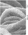
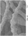
- FIG. 8 shows an example of a plasma-etched nonwoven abrasive article. It can be seen that the visible outer layer of abrasive particles bound along the fibers are not deeply embedded (e.g., they are highly exposed).
- the ionized plasma erodes or removes the binder from the outer surfaces of the nonwoven abrasive member, gradually exposing more surface area of the underlying abrasive particles.
- the conditions of the plasma treatment are adjusted for isotropic etching of the nonwoven abrasive member, uniformly eroding the cross-linked binder even though there are significant height and geometry variations within the nonwoven abrasive member.
- Plasma etching apparatus and conditions are well-known in the art. Briefly, during plasma treatment, plasma created in a vacuum chamber from gas within the chamber is generated and sustained by supplying power (for example, from an RF generator operating at a frequency in the range of 0.001 to 100 MHz) to at least one electrode.
- the electrode system may be symmetric or asymmetric. In some plasma apparatus, electrode surface area ratios between grounded and powered electrodes are from 2:1 to 4:1 or from 3:1 to 4:1.
- the powered electrode may be cooled, e.g., with water.
- plasma deposition can be achieved, for example, by placing the articles in direct contact with the smaller electrode of an asymmetric electrode configuration. This allows the article to act as an electrode due to capacitive coupling between the powered electrode and the article.
- the RF power source provides power at a typical frequency in the range of 0.01 to 50 MHz, or 13.56 MHz or any whole number (e.g., 1, 2, or 3) multiple thereof.
- the RF power source can be an RF generator such as a 13.56 MHz oscillator.
- the power source may be connected to the electrode via a network that acts to match the impedance of the power supply with that of the transmission line (which is usually 50 ohms reactive) so as to effectively transmit RF power through a coaxial transmission line.
- One type of matching network which includes two variable capacitors and an inductor, is available under the designation AMN 3000 from Plasmatherm of St.
- rolls or continuous webs of nonwoven abrasive material can be treated using a continuous plasma reactor using techniques as described in U.S.
- a continuous plasma treatment apparatus typically includes a rotating drum electrode which may be powered by a radio frequency (RF) power source, a grounded chamber which acts as a grounded electrode, a feed reel which continuously supplies to-be-treated articles in the form of a continuous moving web, and a take-up reel which collects the treated article.
- RF radio frequency
- the feed and take up reels are optionally enclosed within the chamber, or can be operated outside of the chamber as long as a low-pressure plasma can be maintained within the chamber. If desired, a concentric grounded electrode can be added near the powered drum electrode for additional spacing control. An inlet supplies suitable treatment gases in vapor or liquid form to the chamber.
- the nonwoven abrasive material is preferably uniformly plasma treated by using alone or in combination, higher gas pressures, longer treatment times, higher power settings, or fluorocarbon (e.g., perfluoropropane (i.e., C 3 F 8 )) gases in combination with oxygen (i.e., O 2 ) to provide isotropic plasma etching conditions.
- fluorocarbon e.g., perfluoropropane (i.e., C 3 F 8 )
- oxygen i.e., O 2
- the isotropic plasma etching conditions can use either pure oxygen gas at higher pressures or a combination of O 2 and C 3 F 8 gases at lower pressures.
- Treatment gas pressures are generally from 50 to 10,000 milliTorr (7 to 1300 Pa), or from 60 to 1,000 milliTorr (8 to 170 Pa), or from 250 to 550 milliTorr (33 to 73 Pa).
- Treatment times are generally from 2 minutes to 15 minutes, or from 4 minutes to 12 minutes, or from 5 minutes to 10 minutes, although this is not a requirement.
- Treatment gases include, for example, either pure oxygen or a mixture of oxygen and C 3 F 8 gases.
- a ratio for the flow rate of the C 3 F 8 gas divided by a total combined flow rate of the C 3 F 8 gas and the O 2 gas is generally from 0.10 to 0.30 or from 0.15 to 0.25, and the total combined gas flow rates are typically 0.1 to 10 liters/minute.
- Treatment power for the plasma etching process is generally set at from 0.1 to 1.0 watts/cm 2 of the electrode area.
- the nonwoven abrasive member may be in any suitable form. Examples include webs, discs, pads, belts, and/or sheets.
- the overlayer composition includes at least one fatty acid metal salt (i.e., a salt of a metal and at least one fatty acid).
- fatty acid metal salts include, for example, metal salts of carboxylic acids represented by the formula R-CO 2 H wherein R represents an aliphatic group having at least 7 carbon atoms, preferably at least 11 carbon atoms, and more preferably at least 18 carbon atoms.
- R is represented by the formula CH 3 (CH 2 ) n CO 2 H wherein n is an integer and is at least 7, preferably at least 9, at least 11, at least 13, at least 15, or even at least 17.
- metal salts of fatty acids staying solid in room temperature are typically preferred.
- saturated fatty acids examples include caprylic acid, capric acid, lauric acid, myristic acid, palmitic acid, stearic acid, arachidic acid, behenic acid, lignoceric acid, and montanic acid.
- unsaturated fatty acids include undecylenic acid, decenoic acid, sapienic acid, vaccenic acid, oleic acid, erucic acid, linoleic acid, ⁇ -linolenic acid, and arachidonic acid.
- preferred fatty acids are capric acid, lauric acid, myristic acid, palmitic acid, stearic acid, behenic acid, montanic acid, and undecylenic acid, and more preferably stearic acid, palmitic acid, myristic acid, lauric acid, behenic acid, and montanic acid.
- Exemplary of metals included in the metal salt of the fatty acid include calcium, zinc, magnesium, aluminum, barium, lithium, sodium, potassium, calcium and silver. Preferred metals include calcium, zinc, lithium, and barium. Combinations of two or more metal salts of fatty acids may also be used. A plurality of different metal salts of fatty acids may enable wetting tension of the overlayer composition to be controlled.
- a binder may be included in the overlayer composition.
- Suitable binders include, for example, alkyl cellulose resins (e.g., methyl cellulose and ethyl cellulose), acrylic resins, alkylamide resins, vinyl acetate resins, styrene-acrylonitrile resins, styrene-butadiene rubbers, butadiene rubbers, natural rubber, chloroprene rubbers and methylbutadiene rubbers. Two or more binding resins may be used in combination.
- the overlayer composition may optionally further comprise additives such as, for example, surface-active agents, plasticizers, antistatic agents, humidifying agents, antifoaming agents, coloring materials, pigments, filler, and combinations thereof.
- additives such as, for example, surface-active agents, plasticizers, antistatic agents, humidifying agents, antifoaming agents, coloring materials, pigments, filler, and combinations thereof.
- the overlayer composition may be prepared by mixing a fatty acid metal salt and a binder, optionally in the presence of a liquid medium (e.g., water and/or a suitable organic solvent), if desired.
- a liquid medium e.g., water and/or a suitable organic solvent
- the content of the metal salt of the fatty acid in the overlayer composition for coating may be in a range of from 10 to 100 weight percent on a dry weight basis, more typically from 60 to 100 percent, although other amounts may be used.
- the abrasive particles are distributed within the nonwoven abrasive member, but have a visible outer layer adjacent to at least one major surface of the lofty open fiber web.
- the overlayer composition is disposed on at least a portion of the visible outer layer of abrasive particles. While the overlayer composition may cover more abrasive particles, in general it is only the outer abrasive particles that contact a surface of a workpiece to be abraded, and hence the greatest benefit is seen when they are contacted by the overlayer composition.
- the overlayer composition may be applied to only a portion of the major surface of the nonwoven abrasive member; for example, so as not to cover some of the abrasive particles adjacent to major surfaces of the lofty open fiber web, or it may be applied to the major surface.
- the overlayer may be applied before or after the abrasive member coatings are finally cured.
- the overlayer composition may be applied by means of brush coating, roll coating, flow coating, die coating, spray coating and the like onto the abrasive surface (i.e., a surface which exerts abrasive action by contacting a workpiece).
- the quantity of overlayer composition to be applied onto the abrasive surface can vary in an appropriate manner with the size and quantity of abrasive particles to be used and the intended application of the abrasive article. Generally, it is approximately 1 to 200 gsm as dried coating weight, and preferably approximately 9 to 40 gsm, although other dried coating weights may also be used.
- the overlayer composition After the overlayer composition is applied onto the abrasive surface, it may be heated and dried under proper conditions of temperature and time until the binding resin is formed into a film.
- the heating conditions may be determined in an appropriate manner.
- Nonwoven abrasive articles according to the present disclosure are useful for abrading a workpiece.
- One such method includes frictionally contacting a nonwoven abrasive article with a surface of the workpiece, and moving at least one of the nonwoven abrasive article or the workpiece relative to the other to abrade at least a portion of the surface.
- workpiece materials include metal, metal alloys, exotic metal alloys, ceramics, glass, wood, wood-like materials, composites, painted surfaces, plastics, reinforced plastics, stone, and/or combinations thereof.
- the workpiece may be flat or have a shape or contour associated with it.
- Exemplary workpieces include metal components, plastic components, particleboard, camshafts, crankshafts, furniture, and turbine blades.
- Nonwoven abrasive articles according to the present disclosure may be used by hand and/or used in combination with a machine.
- Abrading may be conducted under wet or dry conditions.
- Exemplary liquids for wet abrading include water, water containing conventional rust inhibiting compounds, lubricant, oil, soap, and cutting fluid.
- the liquid may also contain, for example, defoamers, and/or degreasers.
- BL16 polyurethane prepolymer obtained as ADIPRENE BL-16 from Chemtura Corporation, Middlebury, Connecticut GEO anti-foam agent, obtained as GEO FM LTX from GEO Specialty Chemicals, Ambler, Pennsylvania P1 red pigment, aqueous dispersion, obtained as RPD-0210 from Sun Chemical Corporation, Cincinnati, Ohio PME propylene glycol monomethyl ether, obtained from Dow Chemical Corporation, Midland, Michigan SR 75% hydroxyethyl ethylene urea in Water, obtained as SR511A from Sartomer Inc., Exton, Pennsylvania S1 ethoxylated nonionic surfactant, obtained as DYNOL 604 from Air Products and Chemicals Inc., Allentown, Pennsylvania S2 secondary alcohol ethoxylate, nonionic surfactant, obtained as TERGITOL 15-S-5 from Dow Chemical Company Resin phenolic resin obtained as PREFERE 80 5077A from Arclin, Mississauga, Ontario, Canada AP280 DURALUM G52 brown aluminum oxide
- polystyrene-acrylate emulsion obtained as JONCRYL 89 from BASF, Florham Park, New Jersey
- 0.5 wt. % sodium lauryl sulfate NaSt Sodium stearate solution consisting of 80.05 wt. % water, 18 wt. % C14-18 sodium stearate, 1.45 wt. % polystyrene-acrylate emulsion (obtained as JONCRYL 89 from BASF), 0.25 wt. % sodium lauryl sulfate and 0.25% of METHOCEL (from Dow Chemical. NaSt1 Sodium stearate solution consisting of 84.5 wt. % water, 15 wt.
- CaSt1 Calcium stearate solution consisting of 84.5 wt. % water, 15 wt. % C14-18 calcium stearate, 0.25 wt. % sodium lauryl sulfate and 0.25 wt. % METHOCEL cellulose ether from Dow Chemical.
- BaSt Barium stearate solution (30 wt. % in water) obtained as EC1686 from eChem Ltd, Leeds, UK.
- P3 Black dye solution containing 45 wt. % of PME, 45 wt. % of water and 10 wt.
- ELCACID NIGROSINE WSJ black dye obtained from Greenville Colorants, LLC, East Jersey City, New Jersey P4 Red dye solution consisting of 89.2 wt. % of PME, 4.1 wt. % of P3, and 6.7 wt. % of DISPERSE RED 17 obtained from American Dyestuff Corp., Clifton, New Jersey.
- Two nonwoven abrasive article test specimens were prepared as 10.2-cm diameter discs that are stacked and then secured to a foam back-up pad by means of a hook-and-loop fastener.
- the back-up pad/fastener assembly had a Shore Durometer OO hardness of 85.
- the abrasive disc and back-up pad assembly was installed on a Schiefer Uniform Abrasion Tester (available from Frazier Precision Instrument Company, Inc. Hagerstown, Maryland), and the abrasive disc was used to abrade an annular ring (10.2 cm outside diameter (OD) x 5.1 cm inside diameter (ID)) of cellulose acetate butyrate polymer from Seelye-Eiler Plastics Inc., Bloomington, Minnesota.
- the load was 5 lb (2.27 kg).
- the test duration was 8 periods of 500 revolutions or cycles of the abrasive disc (4000 cycles total).
- the amount of cellulose acetate butyrate polymer removed was measured at the end of each 500-cycle test period.
- the friction testing machine was a Thwing-Albert Friction/Peel Tester Model 225-100, obtained from Thwing-Albert Instrument Company, West Berlin, New Jersey.
- the friction testing machine was set for a 500-gram load, a 5-second test time, and a speed of 31 cm/min (speed setting "D").
- the weighted test specimen was placed on the test surface and attached to the testing machine by a metal hook. The test machine was zeroed and the test initiated. Three specimens were tested for each example.
- Nonwoven abrasive test specimens were prepared and tested both with and without an overlayer coating of CaSt.
- a lightweight, open, low-density air-laid nonwoven web was prepared from Fiber using a RANDO-WEBBER machine, commercially available from the Rando Machine Corporation of Ard, New York.
- the resulting lofty open fiber web had a nominal basis weight of 37 grains per 24 square inches (155gsm), and the thickness was 0.35 inches (9 mm).
- the web was conveyed to a horizontal two-roll coater, where a pre-bond resin consisting of 74.89 wt. % of PMA, 5.53 wt. % of K450, 15.07 wt. % of BL16, 0.01 wt. % of GEO, and 4.5 wt. % of P4 was applied to the fiber web at a wet add-on weight of 7 grains/24 square inches (29.3 gsm).
- the coated web was conveyed through an oven maintained at 163-177 °C with a residence time of 3 minutes.
- the resulting pre-bonded fiber web was conveyed to a spray booth where a resin/abrasive slurry consisting of 19.11wt.% of L1, 0.40 wt. % of P1, 1.60 wt. % of SR, 0.10 wt. % of S1, 13.58 wt. % of Resin, 1.00 wt. % of S2, and 64.22 wt. % of AP280 was sprayed on the top surface of the web.
- spray nozzles (which are mounted to reciprocate perpendicularly to the direction of web movement) apply the slurry at a wet weight of about 67 grains/24 square inch (280 gsm).
- the slurry-coated web was then heated in an oven maintained at 177 °C for 3 minutes.
- the web was then inverted and the slurry spray coating was applied to the opposite side of the web.
- the coated web was finally heated in an oven maintained at 177 °C for 3 minutes, to yield a nonwoven abrasive member (shown in FIG. 2 ) which was tested according to the Schiefer Test and the KCF Test. Test results are reported in Table 2.
- the nonwoven abrasive member was then brushed with a uniform coating of a 16 wt. % solids CaSt solution and heated in a forced convection oven maintained at 95 °C for 20 minutes to achieve a dry add-on of 18 grains/24 square inches (75 gsm).
- the resulting article was tested according to the Schiefer Test and the results reported in Table 2. The difference in the Schiefer Test results for the uncoated nonwoven abrasive article and the CaSt-coated nonwoven abrasive article are also reported in Table 2.
- Example 2 and Comparative Examples A and B were further embodiments with alumina abrasive particles, and were made identically to Example 1, except that, in the case of Comparative Example A only, the prebond composition consisted of 53.21 wt. % of PMA, 17.94 wt. % often degree xylene, 7.74 wt. % K450, 21.1 wt. % BL16, and 0.01 wt. % GEO, and the slurry spray compositions were as reported in Table 3.
- the resulting nonwoven abrasive members were tested according to the Schiefer Test and the KCF Test.
- the CaSt solution was then applied as recited in Example 1 and the resulting nonwoven abrasive members (shown in respective FIGS. 3-5 ) were tested according to the Schiefer Test. Results are reported in Table 2.
- Example 3 (shown in FIG. 6 ) was a MIRKA MIRLON 18-111-447 SCUFF PAD nonwoven abrasive handpad, obtained from Mirka Abrasives, Inc., Twinsburg, Ohio.
- Example 4 (shown in FIG. 7 ) was a NORTON BEAR-TEX 74700 nonwoven abrasive hand pad, obtained from Saint-Gobain Abrasives Inc., Worcester, Massachusetts.
- Example 5 was prepared to demonstrate the effect of particle exposure on the efficacy of the CaSt coating.
- Example 5 was made by exposing the nonwoven abrasive member of Comparative Example B to a plasma treatment process as described in Example 1 of U.S. Patent Appln. Publ. No. 2010/0255254 A1 (Culler et al. ), with the exception that the treatment time was 20 minutes instead of 10 minutes.
- the kinetic coefficient of friction and the cut of Example 5 were then measured both with and without the CaSt coating, as in the previous Examples.
- the resulting nonwoven abrasive member is shown in FIG. 8 , and the test results are reported in Table 2.
- Examples 6-8 and Comparative Example C were made identically to Example 1, except that the pre-bond composition was 78.98% PMA, 5.6% K450, 15.26% BL16, 0.01% GEO, and 0.151.16% P2; and the slurry spray compositions was that shown in Table 3.
- the resulting nonwoven abrasive members (shown in respective FIGS. 9-12 ) were tested according to the Schiefer Test and the KCF Test.
- Example 2 The CaSt solution was then applied as recited in Example 1, and the resulting nonwoven abrasive articles were tested according to the Schiefer Test. Results are reported in Table 2.
- Example 9 (shown in FIG. 13 ) was MIRKA MIRLON 18-111-448 SCUFF PAD nonwoven abrasive handpad, obtained from Mirka Abrasives, Inc.
- Example 10 (shown in FIG. 14 ) was a NORTON BEAR-TEX 74800 nonwoven abrasive hand pad, obtained from Saint-Gobain Abrasives Inc.
- Example 11 (shown in FIG. 15 ) was a SCOTCH-BRITE DURABLE FLEX S ULF nonwoven abrasive hand pad from 3M Company, Saint Paul, Minnesota.
- Example 12 (shown in FIG. 16 ) was a SCOTCH-BRITE 7448B nonwoven abrasive hand pad from 3M Company.
- Examples 13-19 were prepared to show the effects of type of stearate at various add-ons, and were prepared identically to Example 7, with the exception that either CaSt or LiSt was applied topically according to the compositions reported in Table 4. Schiefer Test results for uncoated and variously coated examples are reported in Table 4.
- FIGS. 17-23 show the nonwoven abrasive members used in Examples 13-19, respectively.
- Examples 17 and 18 were a repeat of Example 7, with the exception that a constant amount of two different metal salts was applied as reported in Table 4.
- Examples -22-25 were prepared to show the effects of various metal stearate salts with the same add-on weight (18 gsm), and were prepared identically to Example 7, with the exception that either CaSt1, NaSt, NaSt1, or BaSt was applied topically according to the compositions reported in Table 5, and Examples 22 and 23 were prepared without a binder in the overlayer composition. Schiefer Test results for uncoated and variously coated examples are reported in Table 5.
Claims (10)
- Ein Vliesschleifgegenstand (100), aufweisend:a) ein Vliesschleifelement (110), das eine Arbeitsoberfläche (142, 144) vorweist, wobei das Vliesschleifelement (110) aufweist:eine füllige offene Faserbahn (120), aufweisend Fasern (130), die aneinander gebunden sind;Schleifteilchen (150), die einen durchschnittlichen Teilchendurchmesser vorweisen, die an mindestens einem Abschnitt der Fasern (130) durch ein Bindemittelmaterial (155) haften, wobei mindestens ein Abschnitt der Schleifteilchen (150) eine sichtbare Außenschicht (165) der Schleifteilchen (150) entlang der Fasern (130) angrenzend an die Arbeitsoberfläche (142, 144) des Vliesschleifelements (110) ausbildet, wobei auf einer numerischen Basis mindestens 80 Prozent der Schleifteilchen (150) in der sichtbaren Außenschicht (165) erkennbare Umrisse (170) vorweisen; undb) eine Überschichtzusammensetzung (160), die auf mindestens einem Abschnitt der sichtbaren Außenschicht (165) der Schleifteilchen (150) angeordnet ist, wodurch der Vliesschleifgegenstand (100) ausgebildet wird, wobei der Vliesschleifgegenstand dadurch gekennzeichnet, ist dass die Überschichtzusammensetzung (160) ein Fettsäuremetallsalz aufweist, und dadurch, dass die Schleifteilchen (150) in der sichtbaren Außenschicht (165) eng gepackt sind, wobei der Begriff "eng gepackt" in Bezug auf Schleifteilchen bedeutet, dass im Wesentlichen alle der Schleifteilchen innerhalb eines Abstands zwischen Außenoberflächen, die dem durchschnittlichen Teilchendurchmesser entsprechen, zu dem nächstgelegenen Schleifteilchen liegen.
- Der Vliesschleifgegenstand (100) nach Anspruch 1, wobei die sichtbare Außenschicht (165) der Schleifteilchen (150) Spalten (180) aufweist, die zwischen angrenzenden der Schleifteilchen (150) angeordnet sind.
- Der Vliesschleifgegenstand (100) nach Anspruch 1 oder 2, wobei sich mindestens ein Abschnitt der Schleifteilchen (150) in der sichtbaren Außenschicht (165) der Schleifteilchen (150) miteinander überlappt.
- Der Vliesschleifgegenstand (100) nach einem der Ansprüche 1 bis 3, wobei die Überschichtzusammensetzung (160) ein Basisgewicht von mindestens 2,5 Gramm pro Quadratmeter vorweist.
- Ein Verfahren zum Herstellen eines Vliesschleifgegenstands (100), das Verfahren sequentiell aufweisend:a) Bereitstellen eines Vliesschleifelements (110), das eine Arbeitsoberfläche (142, 144) vorweist, wobei das Vliesschleifelement (110) aufweist:eine füllige offene Faserbahn (120), aufweisend Fasern (130), die aneinander gebunden sind;Schleifteilchen (150), die an mindestens einem Abschnitt der Fasern (130) durch ein Bindemittelmaterial (165) haften, wobei mindestens ein Abschnitt der Schleifteilchen (150) eine sichtbare Außenschicht (165) der Schleifteilchen (150) entlang der Fasern (130) angrenzend an die Arbeitsoberfläche (142, 144) des Vliesschleifelements (110) ausbildet, wobei auf einer numerischen Basis mindestens 80 Prozent der Schleifteilchen (150) in der sichtbaren Außenschicht (165) erkennbare Umrisse (170) vorweisen; undb) Anordnen einer Überschichtzusammensetzung (160) auf mindestens einem Abschnitt der sichtbaren Außenschicht (165) der Schleifteilchen (150), wodurch der Vliesschleifgegenstand (100) ausgebildet wird, wobei das Verfahren dadurch gekennzeichnet ist, dass die Überschichtzusammensetzung (160) ein Fettsäuremetallsalz aufweist, und dadurch, dass die Schleifteilchen (150) in der sichtbaren Außenschicht (165) eng gepackt sind, wobei der Begriff "eng gepackt" in Bezug auf Schleifteilchen bedeutet, dass im Wesentlichen alle der Schleifteilchen innerhalb eines Abstands zwischen äußeren Oberflächen, die dem durchschnittlichen Teilchendurchmesser entsprechen, zu dem nächstgelegenen Schleifteilchen liegen.
- Das Verfahren nach Anspruch 5, wobei die sichtbare Außenschicht (165) der Schleifteilchen (150) Spalten (180) aufweist, die zwischen angrenzenden der Schleifteilchen (150) angeordnet sind.
- Das Verfahren nach Anspruch 5, wobei sich mindestens ein Abschnitt der Schleifteilchen (150) in der sichtbaren Außenschicht (165) der Schleifteilchen (150) miteinander überlappt.
- Ein Verfahren zum Herstellen eines Vliesschleifgegenstands (100), das Verfahren aufweisend:a) Bereitstellen eines Vliesschleifelements (110), das eine Arbeitsoberfläche (142, 144) vorweist, wobei das Vliesschleifelement (110) aufweist:eine füllige offene Faserbahn (120), aufweisend Fasern (130), die aneinander gebunden sind; undSchleifteilchen (150), die einen durchschnittlichen Teilchendurchmesser vorweisen, die an mindestens einem Abschnitt der Fasern (130) durch ein Bindemittelmaterial (155) haften, wobei mindestens ein Abschnitt der Schleifteilchen (150) eine sichtbare Außenschicht (165) der Schleifteilchen (150) entlang der Fasern (130) angrenzend an die Arbeitsoberfläche (142, 144) des Vliesschleifelements (110) ausbildet, wobei die Schleifteilchen (150) in der sichtbaren Außenschicht (165) eng gepackt sind, wobei der Begriff "eng gepackt" in Bezug auf Schleifteilchen bedeutet, dass im Wesentlichen alle der Schleifteilchen innerhalb eines Abstands zwischen äußeren Oberflächen, die dem durchschnittlichen Teilchendurchmesser entsprechen, zu dem nächstgelegenen Schleifteilchen liegen; wobei mindestens ein Abschnitt der Schleifteilchen (150) mindestens teilweise in das Bindemittelmaterial (155) eingebettet ist; undb) Plasmaätzen eines Abschnitts des Bindemittelmaterials (155) angrenzend an die Arbeitsoberfläche (142, 144), um Abschnitte der Schleifteilchen (150) freizulegen, die zuvor in das Bindemittelmaterial (155) eingebettet waren, um ein plasmageätztes Vliesschleifelement (110) bereitzustellen; undc) Anordnen einer Überschichtzusammensetzung (160) auf mindestens einem Abschnitt der Arbeitsoberfläche (142, 144) des plasmageätzten Vliesschleifelements (110), wobei die Überschichtzusammensetzung (160) ein Fettsäuremetallsalz aufweist.
- Das Verfahren nach Anspruch 8, wobei die Schleifteilchen (150) eine durchschnittliche Teilchengrößen von weniger als oder gleich 125 Mikrometer vorweisen.
- Das Verfahren nach Anspruch 8 oder 9, wobei die Überschichtzusammensetzung (160) ein Basisgewicht von mindestens 2,5 Gramm pro Quadratmeter vorweist.
Applications Claiming Priority (2)
| Application Number | Priority Date | Filing Date | Title |
|---|---|---|---|
| US201361806630P | 2013-03-29 | 2013-03-29 | |
| PCT/US2014/031248 WO2014160578A1 (en) | 2013-03-29 | 2014-03-19 | Nonwoven abrasive articles and methods of making the same |
Publications (3)
| Publication Number | Publication Date |
|---|---|
| EP2978567A1 EP2978567A1 (de) | 2016-02-03 |
| EP2978567A4 EP2978567A4 (de) | 2016-11-16 |
| EP2978567B1 true EP2978567B1 (de) | 2023-12-27 |
Family
ID=51625455
Family Applications (1)
| Application Number | Title | Priority Date | Filing Date |
|---|---|---|---|
| EP14774036.9A Active EP2978567B1 (de) | 2013-03-29 | 2014-03-19 | Vliesschleifartikel und verfahren zur herstellung davon |
Country Status (6)
| Country | Link |
|---|---|
| US (2) | US10414023B2 (de) |
| EP (1) | EP2978567B1 (de) |
| JP (1) | JP6591397B2 (de) |
| CN (1) | CN105121096B (de) |
| MX (1) | MX2015013566A (de) |
| WO (1) | WO2014160578A1 (de) |
Families Citing this family (15)
| Publication number | Priority date | Publication date | Assignee | Title |
|---|---|---|---|---|
| EP2794983B1 (de) * | 2011-12-20 | 2015-11-04 | Celanese Emulsions GmbH | Beschichtungszusammensetzungen für teppiche mit verbesserter stabilität aus vinylacetat-/ethylencopolymerdispersionen |
| US10414023B2 (en) * | 2013-03-29 | 2019-09-17 | 3M Innovative Properties Company | Nonwoven abrasive articles and methods of making the same |
| EP2996818B1 (de) | 2013-05-17 | 2018-07-25 | 3M Innovative Properties Company | Verfahren zur herstellung von leicht zu reinigende oberfläche |
| CA2931631C (en) * | 2013-12-06 | 2018-06-19 | Saint-Gobain Abrasives, Inc. | Coated abrasive article including a non-woven material |
| EP3442748A1 (de) | 2016-04-13 | 2019-02-20 | 3M Innovative Properties Company | Schleifartikel |
| WO2018005111A1 (en) * | 2016-07-01 | 2018-01-04 | 3M Innovative Properties Company | Nonwoven abrasive article including abrasive particles |
| CN110546319B (zh) * | 2017-04-28 | 2022-06-28 | 3M创新有限公司 | 大纤度非织造纤维辐材 |
| CN108559446B (zh) * | 2018-03-27 | 2020-11-06 | 西北工业大学 | 一种纤维增强树脂基湿式摩擦材料及制备方法 |
| CA3105329A1 (en) * | 2018-05-10 | 2019-11-14 | 3M Innovative Properties Company | Non-scratch composition and abrasive cleaning article |
| WO2020026060A1 (en) * | 2018-07-30 | 2020-02-06 | 3M Innovative Properties Company | Self-contained buffing articles |
| WO2020212779A1 (en) * | 2019-04-16 | 2020-10-22 | 3M Innovative Properties Company | Abrasive article and method of making the same |
| JP6779541B1 (ja) * | 2019-07-02 | 2020-11-04 | 株式会社東京ダイヤモンド工具製作所 | 合成砥石 |
| JP7084904B2 (ja) * | 2019-11-07 | 2022-06-15 | 株式会社和倉ダスキン | 汚れ除去用繊維製品 |
| CN110919557A (zh) * | 2019-11-28 | 2020-03-27 | 东莞金太阳研磨股份有限公司 | 一种自洁透水柔软基材磨具的制备工艺 |
| CN112692742B (zh) * | 2020-12-23 | 2021-12-14 | 苏州远东砂轮有限公司 | 一种柔韧纸基砂纸的制造方法、砂纸 |
Family Cites Families (73)
| Publication number | Priority date | Publication date | Assignee | Title |
|---|---|---|---|---|
| DE1694594C3 (de) | 1960-01-11 | 1975-05-28 | Minnesota Mining And Manufacturing Co., Saint Paul, Minn. (V.St.A.) | Reinigungs- und Polierkörper |
| US4314827A (en) | 1979-06-29 | 1982-02-09 | Minnesota Mining And Manufacturing Company | Non-fused aluminum oxide-based abrasive mineral |
| CA1193870A (en) * | 1980-08-14 | 1985-09-24 | Peter N. Tomlinson | Abrasive product |
| US4623364A (en) | 1984-03-23 | 1986-11-18 | Norton Company | Abrasive material and method for preparing the same |
| US4609380A (en) | 1985-02-11 | 1986-09-02 | Minnesota Mining And Manufacturing Company | Abrasive wheels |
| CA1254238A (en) | 1985-04-30 | 1989-05-16 | Alvin P. Gerk | Process for durable sol-gel produced alumina-based ceramics, abrasive grain and abrasive products |
| US4770671A (en) | 1985-12-30 | 1988-09-13 | Minnesota Mining And Manufacturing Company | Abrasive grits formed of ceramic containing oxides of aluminum and yttrium, method of making and using the same and products made therewith |
| US4881951A (en) | 1987-05-27 | 1989-11-21 | Minnesota Mining And Manufacturing Co. | Abrasive grits formed of ceramic containing oxides of aluminum and rare earth metal, method of making and products made therewith |
| AU604899B2 (en) | 1987-05-27 | 1991-01-03 | Minnesota Mining And Manufacturing Company | Abrasive grits formed of ceramic, impregnation method of making the same and products made therewith |
| US5011508A (en) | 1988-10-14 | 1991-04-30 | Minnesota Mining And Manufacturing Company | Shelling-resistant abrasive grain, a method of making the same, and abrasive products |
| US4964883A (en) | 1988-12-12 | 1990-10-23 | Minnesota Mining And Manufacturing Company | Ceramic alumina abrasive grains seeded with iron oxide |
| US5244477A (en) | 1989-04-28 | 1993-09-14 | Norton Company | Sintered sol gel alumina abrasive filaments |
| US5009676A (en) | 1989-04-28 | 1991-04-23 | Norton Company | Sintered sol gel alumina abrasive filaments |
| US5103598A (en) | 1989-04-28 | 1992-04-14 | Norton Company | Coated abrasive material containing abrasive filaments |
| US4988554A (en) | 1989-06-23 | 1991-01-29 | Minnesota Mining And Manufacturing Company | Abrasive article coated with a lithium salt of a fatty acid |
| US5178646A (en) | 1992-01-22 | 1993-01-12 | Minnesota Mining And Manufacturing Company | Coatable thermally curable binder presursor solutions modified with a reactive diluent, abrasive articles incorporating same, and methods of making said abrasive articles |
| US5355636A (en) * | 1992-10-01 | 1994-10-18 | Minnesota Mining And Manufacturing Company | Tear resistant coated abrasive article |
| US5549962A (en) | 1993-06-30 | 1996-08-27 | Minnesota Mining And Manufacturing Company | Precisely shaped particles and method of making the same |
| US5372620A (en) | 1993-12-13 | 1994-12-13 | Saint Gobain/Norton Industrial Ceramics Corporation | Modified sol-gel alumina abrasive filaments |
| CN1156424A (zh) * | 1994-08-30 | 1997-08-06 | 美国3M公司 | 非织造磨料制品及其制造方法 |
| US5591239A (en) | 1994-08-30 | 1997-01-07 | Minnesota Mining And Manufacturing Company | Nonwoven abrasive article and method of making same |
| JP3751025B2 (ja) | 1995-12-15 | 2006-03-01 | ザ デクスター コーポレイション | 研摩性不織繊維ウェブ材料及びその製造方法 |
| WO1997042003A1 (en) | 1996-05-03 | 1997-11-13 | Minnesota Mining And Manufacturing Company | Method and apparatus for manufacturing abrasive articles |
| EP0912294B1 (de) | 1996-05-03 | 2003-04-16 | Minnesota Mining And Manufacturing Company | Nichtgewebte schleifmittel |
| BR9708934A (pt) * | 1996-05-08 | 1999-08-03 | Minnesota Mining & Mfg | Artigo abrasivo abrasivo e processo para produzir um artigo abrasivo |
| US5704952A (en) | 1996-05-08 | 1998-01-06 | Minnesota Mining And Manufacturing Company | Abrasive article comprising an antiloading component |
| US5667542A (en) | 1996-05-08 | 1997-09-16 | Minnesota Mining And Manufacturing Company | Antiloading components for abrasive articles |
| US6475253B2 (en) * | 1996-09-11 | 2002-11-05 | 3M Innovative Properties Company | Abrasive article and method of making |
| US5888594A (en) | 1996-11-05 | 1999-03-30 | Minnesota Mining And Manufacturing Company | Process for depositing a carbon-rich coating on a moving substrate |
| US5948166A (en) | 1996-11-05 | 1999-09-07 | 3M Innovative Properties Company | Process and apparatus for depositing a carbon-rich coating on a moving substrate |
| US6039775A (en) * | 1997-11-03 | 2000-03-21 | 3M Innovative Properties Company | Abrasive article containing a grinding aid and method of making the same |
| WO1999051401A1 (en) * | 1998-04-06 | 1999-10-14 | Acs Industries Inc. | Antimicrobial scrub pad |
| EP0988698B1 (de) | 1998-04-08 | 2005-01-12 | Nortel Networks Limited | Gyrator |
| US6228133B1 (en) * | 1998-05-01 | 2001-05-08 | 3M Innovative Properties Company | Abrasive articles having abrasive layer bond system derived from solid, dry-coated binder precursor particles having a fusible, radiation curable component |
| US6261682B1 (en) | 1998-06-30 | 2001-07-17 | 3M Innovative Properties | Abrasive articles including an antiloading composition |
| US6059850A (en) | 1998-07-15 | 2000-05-09 | 3M Innovative Properties Company | Resilient abrasive article with hard anti-loading size coating |
| JP3915334B2 (ja) * | 1999-08-30 | 2007-05-16 | 株式会社豊田自動織機 | 燃料電池用水素供給システム、燃料リサイクル方法、液体運搬用移動体、給油設備及び燃料リサイクルシステム |
| US6287184B1 (en) * | 1999-10-01 | 2001-09-11 | 3M Innovative Properties Company | Marked abrasive article |
| JP2001334473A (ja) | 2000-05-30 | 2001-12-04 | Nihon Micro Coating Co Ltd | 研磨シート及びその製造方法 |
| US6521004B1 (en) * | 2000-10-16 | 2003-02-18 | 3M Innovative Properties Company | Method of making an abrasive agglomerate particle |
| US20020173214A1 (en) | 2001-04-12 | 2002-11-21 | 3M Innovative Properties Company | Cleaning articles and method of making |
| US7607189B2 (en) | 2004-07-14 | 2009-10-27 | Colgate-Palmolive | Oral care implement |
| US6572666B1 (en) * | 2001-09-28 | 2003-06-03 | 3M Innovative Properties Company | Abrasive articles and methods of making the same |
| US7887889B2 (en) | 2001-12-14 | 2011-02-15 | 3M Innovative Properties Company | Plasma fluorination treatment of porous materials |
| US6979713B2 (en) | 2002-11-25 | 2005-12-27 | 3M Innovative Properties Company | Curable compositions and abrasive articles therefrom |
| US20040098923A1 (en) | 2002-11-25 | 2004-05-27 | 3M Innovative Properties Company | Nonwoven abrasive articles and methods for making and using the same |
| DE602004008253T2 (de) | 2003-04-25 | 2008-05-08 | 3M Innovative Properties Co., St. Paul | Scheuerlappen |
| US20040253893A1 (en) | 2003-06-10 | 2004-12-16 | Massimiliano Castellani | Non-woven abrasive wipe and method of making same |
| US7763676B2 (en) * | 2003-08-25 | 2010-07-27 | Dow Global Technologies Inc. | Aqueous polymer dispersions and products from those dispersions |
| US7195658B2 (en) | 2003-10-17 | 2007-03-27 | Saint-Gobain Abrasives, Inc. | Antiloading compositions and methods of selecting same |
| JP2006022272A (ja) | 2004-07-09 | 2006-01-26 | Three M Innovative Properties Co | 目詰まり防止被膜を有する研磨材 |
| GB0420054D0 (en) | 2004-09-09 | 2004-10-13 | 3M Innovative Properties Co | Floor cleaning pads and preparation thereof |
| US7195360B2 (en) | 2004-12-28 | 2007-03-27 | 3M Innovative Properties Company | Prismatic retroreflective article and method |
| US7811342B1 (en) * | 2006-03-08 | 2010-10-12 | Saint-Gobain Abrasives, Inc. | Coated abrasive tools from non-blocked urethane prepolymer |
| US7985269B2 (en) * | 2006-12-04 | 2011-07-26 | 3M Innovative Properties Company | Nonwoven abrasive articles and methods of making the same |
| US20080160879A1 (en) * | 2006-12-31 | 2008-07-03 | 3M Innovative Properties Company | Method of abrading a zirconium-based alloy workpiece |
| JP2008266397A (ja) | 2007-04-18 | 2008-11-06 | Three M Innovative Properties Co | 研磨材用目詰まり防止組成物及び目詰まり防止皮膜を有する研磨材 |
| JP5414694B2 (ja) | 2007-12-27 | 2014-02-12 | スリーエム イノベイティブ プロパティズ カンパニー | 成形され断裂された研磨粒子及びこの研磨粒子を使用する研磨物品、並びにそれらの作製方法 |
| US8123828B2 (en) | 2007-12-27 | 2012-02-28 | 3M Innovative Properties Company | Method of making abrasive shards, shaped abrasive particles with an opening, or dish-shaped abrasive particles |
| US8444458B2 (en) * | 2007-12-31 | 2013-05-21 | 3M Innovative Properties Company | Plasma treated abrasive article and method of making same |
| US8142532B2 (en) | 2008-12-17 | 2012-03-27 | 3M Innovative Properties Company | Shaped abrasive particles with an opening |
| US8142531B2 (en) | 2008-12-17 | 2012-03-27 | 3M Innovative Properties Company | Shaped abrasive particles with a sloping sidewall |
| US8142891B2 (en) | 2008-12-17 | 2012-03-27 | 3M Innovative Properties Company | Dish-shaped abrasive particles with a recessed surface |
| RU2506152C2 (ru) | 2008-12-17 | 2014-02-10 | 3М Инновейтив Пропертиз Компани | Фасонные абразивные частицы с канавками |
| SG181520A1 (en) | 2009-12-29 | 2012-07-30 | Saint Gobain Abrasives Inc | Smear-free nonwoven composite abrasives |
| CN102958649B (zh) | 2010-06-28 | 2015-08-19 | 3M创新有限公司 | 非织造磨轮 |
| US20130130600A1 (en) | 2010-07-28 | 2013-05-23 | 3M Innovative Properties Company | Hybrid Abrasive Hand Pad and Method of Abrading a Surface |
| CA2813086C (en) | 2010-10-06 | 2017-05-30 | Saint-Gobain Abrasives, Inc. | Nonwoven composite abrasive comprising diamond abrasive particles |
| JP2012219381A (ja) | 2011-04-04 | 2012-11-12 | Oji Paper Co Ltd | 紙カップ原紙 |
| JP2012219391A (ja) | 2011-04-05 | 2012-11-12 | Japan Vilene Co Ltd | 固体粒子担持繊維及び固体粒子担持繊維シートの製造方法及びそれらの製造装置 |
| WO2012141905A2 (en) | 2011-04-14 | 2012-10-18 | 3M Innovative Properties Company | Nonwoven abrasive article containing elastomer bound agglomerates of shaped abrasive grain |
| WO2013003650A2 (en) * | 2011-06-30 | 2013-01-03 | Saint-Gobain Abrasives, Inc. | Non-woven abrasive article with extended life |
| US10414023B2 (en) * | 2013-03-29 | 2019-09-17 | 3M Innovative Properties Company | Nonwoven abrasive articles and methods of making the same |
-
2014
- 2014-03-19 US US14/780,913 patent/US10414023B2/en active Active
- 2014-03-19 JP JP2016505499A patent/JP6591397B2/ja active Active
- 2014-03-19 CN CN201480019284.7A patent/CN105121096B/zh active Active
- 2014-03-19 MX MX2015013566A patent/MX2015013566A/es unknown
- 2014-03-19 EP EP14774036.9A patent/EP2978567B1/de active Active
- 2014-03-19 WO PCT/US2014/031248 patent/WO2014160578A1/en active Application Filing
-
2019
- 2019-07-26 US US16/523,419 patent/US10850368B2/en active Active
Also Published As
| Publication number | Publication date |
|---|---|
| WO2014160578A1 (en) | 2014-10-02 |
| EP2978567A1 (de) | 2016-02-03 |
| CN105121096A (zh) | 2015-12-02 |
| US10414023B2 (en) | 2019-09-17 |
| MX2015013566A (es) | 2016-02-05 |
| JP2016514627A (ja) | 2016-05-23 |
| US20190345897A1 (en) | 2019-11-14 |
| US20160052106A1 (en) | 2016-02-25 |
| CN105121096B (zh) | 2018-10-16 |
| US10850368B2 (en) | 2020-12-01 |
| EP2978567A4 (de) | 2016-11-16 |
| JP6591397B2 (ja) | 2019-10-16 |
Similar Documents
| Publication | Publication Date | Title |
|---|---|---|
| US10850368B2 (en) | Nonwoven abrasive articles and methods of making the same | |
| EP3283258B1 (de) | Vliesschleifartikel und verfahren zur herstellung davon | |
| JP5020332B2 (ja) | 不織布研磨物品及びその製造方法 | |
| EP3046730B1 (de) | Vlies-schleifartikel mit einer wachsentladungsverbindung sowie verfahren zur verwendung davon | |
| CN103068525B (zh) | 混合式手工研磨垫以及研磨表面的方法 | |
| CA3086438A1 (en) | Abrasive articles including an anti-loading size layer | |
| WO2008055021A1 (en) | Abrasive article and method of making and using the same | |
| EP2640553B1 (de) | Gewundener schleifartikel und herstellungsverfahren dafür | |
| CN113474122B (zh) | 磨料制品及其制备和使用方法 | |
| WO2023156980A1 (en) | Nonwoven abrasive article and methods of making the same | |
| WO2020165683A1 (en) | Abrasive articles and methods of making and using the same |
Legal Events
| Date | Code | Title | Description |
|---|---|---|---|
| PUAI | Public reference made under article 153(3) epc to a published international application that has entered the european phase |
Free format text: ORIGINAL CODE: 0009012 |
|
| 17P | Request for examination filed |
Effective date: 20151015 |
|
| AK | Designated contracting states |
Kind code of ref document: A1 Designated state(s): AL AT BE BG CH CY CZ DE DK EE ES FI FR GB GR HR HU IE IS IT LI LT LU LV MC MK MT NL NO PL PT RO RS SE SI SK SM TR |
|
| AX | Request for extension of the european patent |
Extension state: BA ME |
|
| DAX | Request for extension of the european patent (deleted) | ||
| A4 | Supplementary search report drawn up and despatched |
Effective date: 20161019 |
|
| RIC1 | Information provided on ipc code assigned before grant |
Ipc: B24D 18/00 20060101ALI20161013BHEP Ipc: B24D 11/00 20060101ALI20161013BHEP Ipc: B24D 3/34 20060101ALI20161013BHEP Ipc: B24D 3/32 20060101AFI20161013BHEP |
|
| STAA | Information on the status of an ep patent application or granted ep patent |
Free format text: STATUS: EXAMINATION IS IN PROGRESS |
|
| 17Q | First examination report despatched |
Effective date: 20191111 |
|
| STAA | Information on the status of an ep patent application or granted ep patent |
Free format text: STATUS: EXAMINATION IS IN PROGRESS |
|
| GRAP | Despatch of communication of intention to grant a patent |
Free format text: ORIGINAL CODE: EPIDOSNIGR1 |
|
| STAA | Information on the status of an ep patent application or granted ep patent |
Free format text: STATUS: GRANT OF PATENT IS INTENDED |
|
| INTG | Intention to grant announced |
Effective date: 20230830 |
|
| GRAS | Grant fee paid |
Free format text: ORIGINAL CODE: EPIDOSNIGR3 |
|
| GRAA | (expected) grant |
Free format text: ORIGINAL CODE: 0009210 |
|
| STAA | Information on the status of an ep patent application or granted ep patent |
Free format text: STATUS: THE PATENT HAS BEEN GRANTED |
|
| AK | Designated contracting states |
Kind code of ref document: B1 Designated state(s): AL AT BE BG CH CY CZ DE DK EE ES FI FR GB GR HR HU IE IS IT LI LT LU LV MC MK MT NL NO PL PT RO RS SE SI SK SM TR |
|
| REG | Reference to a national code |
Ref country code: GB Ref legal event code: FG4D |
|
| REG | Reference to a national code |
Ref country code: CH Ref legal event code: EP |
|
| P01 | Opt-out of the competence of the unified patent court (upc) registered |
Effective date: 20231124 |
|
| REG | Reference to a national code |
Ref country code: DE Ref legal event code: R096 Ref document number: 602014089203 Country of ref document: DE |
|
| REG | Reference to a national code |
Ref country code: IE Ref legal event code: FG4D |
|
| PG25 | Lapsed in a contracting state [announced via postgrant information from national office to epo] |
Ref country code: GR Free format text: LAPSE BECAUSE OF FAILURE TO SUBMIT A TRANSLATION OF THE DESCRIPTION OR TO PAY THE FEE WITHIN THE PRESCRIBED TIME-LIMIT Effective date: 20240328 |
|
| REG | Reference to a national code |
Ref country code: LT Ref legal event code: MG9D |
|
| PG25 | Lapsed in a contracting state [announced via postgrant information from national office to epo] |
Ref country code: LT Free format text: LAPSE BECAUSE OF FAILURE TO SUBMIT A TRANSLATION OF THE DESCRIPTION OR TO PAY THE FEE WITHIN THE PRESCRIBED TIME-LIMIT Effective date: 20231227 |