EP2977691B1 - Système de refroidissement et système de chauffage - Google Patents
Système de refroidissement et système de chauffage Download PDFInfo
- Publication number
- EP2977691B1 EP2977691B1 EP13881452.0A EP13881452A EP2977691B1 EP 2977691 B1 EP2977691 B1 EP 2977691B1 EP 13881452 A EP13881452 A EP 13881452A EP 2977691 B1 EP2977691 B1 EP 2977691B1
- Authority
- EP
- European Patent Office
- Prior art keywords
- pipeline
- gas suction
- heat exchanger
- refrigerating system
- control valve
- Prior art date
- Legal status (The legal status is an assumption and is not a legal conclusion. Google has not performed a legal analysis and makes no representation as to the accuracy of the status listed.)
- Active
Links
- 238000010438 heat treatment Methods 0.000 title claims description 95
- 238000001816 cooling Methods 0.000 title description 11
- 239000003507 refrigerant Substances 0.000 claims description 63
- 230000005494 condensation Effects 0.000 claims description 11
- 238000009833 condensation Methods 0.000 claims description 11
- 238000001704 evaporation Methods 0.000 claims description 10
- 230000008020 evaporation Effects 0.000 claims description 10
- 230000007246 mechanism Effects 0.000 claims description 10
- 238000004781 supercooling Methods 0.000 claims description 9
- 238000005057 refrigeration Methods 0.000 description 16
- 230000008859 change Effects 0.000 description 12
- XLYOFNOQVPJJNP-UHFFFAOYSA-N water Substances O XLYOFNOQVPJJNP-UHFFFAOYSA-N 0.000 description 11
- 238000010586 diagram Methods 0.000 description 10
- 230000006866 deterioration Effects 0.000 description 8
- 239000007788 liquid Substances 0.000 description 8
- 125000003236 benzoyl group Chemical group [H]C1=C([H])C([H])=C(C([H])=C1[H])C(*)=O 0.000 description 5
- 238000004364 calculation method Methods 0.000 description 5
- 230000006835 compression Effects 0.000 description 4
- 238000007906 compression Methods 0.000 description 4
- 230000008901 benefit Effects 0.000 description 3
- 230000003247 decreasing effect Effects 0.000 description 3
- LVGUZGTVOIAKKC-UHFFFAOYSA-N 1,1,1,2-tetrafluoroethane Chemical compound FCC(F)(F)F LVGUZGTVOIAKKC-UHFFFAOYSA-N 0.000 description 2
- 238000004378 air conditioning Methods 0.000 description 2
- 238000002347 injection Methods 0.000 description 2
- 239000007924 injection Substances 0.000 description 2
- 239000000463 material Substances 0.000 description 2
- 238000000034 method Methods 0.000 description 2
- CDOOAUSHHFGWSA-OWOJBTEDSA-N (e)-1,3,3,3-tetrafluoroprop-1-ene Chemical compound F\C=C\C(F)(F)F CDOOAUSHHFGWSA-OWOJBTEDSA-N 0.000 description 1
- 238000010835 comparative analysis Methods 0.000 description 1
- 230000001351 cycling effect Effects 0.000 description 1
- 230000000694 effects Effects 0.000 description 1
- 238000012986 modification Methods 0.000 description 1
- 230000004048 modification Effects 0.000 description 1
- 238000013021 overheating Methods 0.000 description 1
- 230000008569 process Effects 0.000 description 1
- 238000000926 separation method Methods 0.000 description 1
- 239000000243 solution Substances 0.000 description 1
- 238000010257 thawing Methods 0.000 description 1
Images


Classifications
-
- F—MECHANICAL ENGINEERING; LIGHTING; HEATING; WEAPONS; BLASTING
- F25—REFRIGERATION OR COOLING; COMBINED HEATING AND REFRIGERATION SYSTEMS; HEAT PUMP SYSTEMS; MANUFACTURE OR STORAGE OF ICE; LIQUEFACTION SOLIDIFICATION OF GASES
- F25B—REFRIGERATION MACHINES, PLANTS OR SYSTEMS; COMBINED HEATING AND REFRIGERATION SYSTEMS; HEAT PUMP SYSTEMS
- F25B31/00—Compressor arrangements
- F25B31/006—Cooling of compressor or motor
-
- F—MECHANICAL ENGINEERING; LIGHTING; HEATING; WEAPONS; BLASTING
- F25—REFRIGERATION OR COOLING; COMBINED HEATING AND REFRIGERATION SYSTEMS; HEAT PUMP SYSTEMS; MANUFACTURE OR STORAGE OF ICE; LIQUEFACTION SOLIDIFICATION OF GASES
- F25B—REFRIGERATION MACHINES, PLANTS OR SYSTEMS; COMBINED HEATING AND REFRIGERATION SYSTEMS; HEAT PUMP SYSTEMS
- F25B1/00—Compression machines, plants or systems with non-reversible cycle
- F25B1/04—Compression machines, plants or systems with non-reversible cycle with compressor of rotary type
-
- F—MECHANICAL ENGINEERING; LIGHTING; HEATING; WEAPONS; BLASTING
- F25—REFRIGERATION OR COOLING; COMBINED HEATING AND REFRIGERATION SYSTEMS; HEAT PUMP SYSTEMS; MANUFACTURE OR STORAGE OF ICE; LIQUEFACTION SOLIDIFICATION OF GASES
- F25B—REFRIGERATION MACHINES, PLANTS OR SYSTEMS; COMBINED HEATING AND REFRIGERATION SYSTEMS; HEAT PUMP SYSTEMS
- F25B13/00—Compression machines, plants or systems, with reversible cycle
-
- F—MECHANICAL ENGINEERING; LIGHTING; HEATING; WEAPONS; BLASTING
- F25—REFRIGERATION OR COOLING; COMBINED HEATING AND REFRIGERATION SYSTEMS; HEAT PUMP SYSTEMS; MANUFACTURE OR STORAGE OF ICE; LIQUEFACTION SOLIDIFICATION OF GASES
- F25B—REFRIGERATION MACHINES, PLANTS OR SYSTEMS; COMBINED HEATING AND REFRIGERATION SYSTEMS; HEAT PUMP SYSTEMS
- F25B41/00—Fluid-circulation arrangements
- F25B41/20—Disposition of valves, e.g. of on-off valves or flow control valves
Definitions
- the present invention relates to a field of household appliances, and more particularly to a refrigerating system and a heating system.
- the motor of a low back pressure rotary compressor is disposed in the shell, and during the operation of the compressor, the motor generates heat due to energy loss, but a low temperature and low pressure environment communicated with the gas suction pipe is present in the shell. Therefore, the sucked low temperature and low pressure gas exchanges heat with the motor, which cools the motor and hence guarantees the reliability of the motor on one hand, but deteriorates the performance of the refrigeration cycle since the sucked gas is heated on the other hand.
- the refrigerating performance and the heating performance in the refrigeration cycle are, in essence, differently affected by the heating of the sucked gas. Therefore, the refrigerating system should be designed according to characteristics when the refrigerating device is in a refrigerating mode or in a heating mode, so as to achieve the double objectives of improving the performance of the refrigerating system and meeting the cooling requirement of the motor.
- WO2007/070060A1 discloses a heat pump, which is provided with a component that has a pulse width modulation control to adjust system capacity.
- the present invention is able to closely tailor the delivered capacity of the heat pump to that which is demanded, without cycling the unit.
- the component has a suction pulse width modulation valve.
- the component which is modulated is the compressor pump unit, and, in particular, a pair of scroll members that are allowed to move into and out of contact with each other.
- the pulse width modulation control device can also be utilized in combination with a heat pump having an economizer function and/or an unloader function.
- EP1553365A2 discloses an air conditioning system for heating and cooling air.
- the air conditioning system which is provided with a compressor for compressing a refrigerant, an outdoor heat exchanger for heat-exchanging the refrigerant with outdoor air, an indoor heat exchanger for heat-exchanging the refrigerant with indoor air, a four-way valve for converting the direction of a refrigerant flow, a refrigerant expansion device installed in a refrigerant pipe connecting the outdoor heat exchanger and the indoor heat exchanger, and a vapour-liquid separator installed in a refrigerant pipe connecting the refrigerant expansion device and the indoor heat exchanger, includes a liquid refrigerant supply pipe; connecting the vapour-liquid separator and an inlet of the compressor for supplying the refrigerant in a liquid state within the vapour-liquid separator to the inlet of the compressor, and a liquid refrigerant supply valve for controlling the supply of the refrigerant in the liquid state through the liquid refrigerant supply pipe.
- US2013/098092A1 discloses a first bypass pipe has one end connected to a main pipe extending from a compressor to an indoor heat exchanger, and its other end branched off into parts that are each connected to the main pipe on an inlet side of an outdoor heat exchanger, and a second bypass pipe has one end connected to an injection port communicating with the compression chamber of the compressor in which compression is taking place and its other end branched off into parts that are each connected to the main pipe on an outlet side of the outdoor heat exchangers.
- a part of the refrigerant discharged from the compressor is supplied from the first bypass pipe to the outdoor heat exchanger to be defrosted, and is then passed through the second bypass pipe and injected from the injection port of the compressor.
- an objective of the present invention is to provide a refrigerating system that can achieve the double objectives of optimizing the performance of the refrigerating system and meeting the cooling requirement of the motor.
- Another objective of the present invention is to provide a heating system that can guarantee the reliability of the motor furthest.
- the solution to the problems of the prior art is given by the invention of claim 1.
- a refrigerating system includes: a low back pressure rotary compressor including a shell, and a motor and a compressing mechanism disposed in the shell respectively, an upper gas suction pipe disposed at an upper part of the shell, a middle gas suction pipe disposed at a middle part of the shell, and an exhaust pipe disposed at the shell; a four-way valve being formed with an exhaust valve port, a gas suction valve port, an outdoor heat exchanger valve port and an indoor heat exchanger valve port, and the exhaust valve port being connected with the exhaust pipe; an outdoor heat exchanger defining an end connected with the outdoor heat exchanger valve port; an indoor heat exchanger defining an end connected with the indoor heat exchanger valve port, and the other end connected with the other end of the outdoor heat exchanger; a throttling element connected between the outdoor heat exchanger and the indoor heat exchanger in series; a control valve assembly being connected with the gas suction valve port, the upper gas suction pipe and the middle gas suction pipe via a first pipeline,
- the control valve assembly controls the gas suction flow of the third pipeline to be larger than that of the second pipeline; when the refrigerating system is in a heating mode, the control valve assembly controls the gas suction flow of the second pipeline to be larger than that of the third pipeline. Therefore, when the refrigerating system is in the refrigerating mode, the gas is mainly sucked via the middle gas suction pipe without going through the motor, thereby reducing the heating degree of the sucked gas by the motor and the deterioration of the performance due to heating.
- the gas suction pipe When the refrigerating system is in the heating mode, the gas is mainly sucked via the upper gas suction pipe and cools the motor after going through the motor so as to maximize the reliability of the motor.
- the refrigerating system according to the present invention also has the additional technical features as follows: Specifically, in the refrigerating mode, a ratio between the gas suction flow of the third pipeline and that of the first pipeline is greater than or equal to 0.6.
- the gas suction flow of the third pipeline is equal to that of the first pipeline.
- a ratio between the gas suction flow of the second pipeline and that of the first pipeline is greater than or equal to 0.6.
- the gas suction flow of the second pipeline is equal to that of the first pipeline.
- control valve assembly includes a first control valve and a second control valve disposed at the second pipeline and the third pipeline respectively.
- control valve assembly is connected with the four-way valve to determine whether the refrigerating system is in the refrigerating mode or the heating mode in accordance with a flow direction of a refrigerant in the four-way valve.
- a heating quality or coefficient of performance (COP) of the refrigerant in the low back pressure rotary compressor improves as a superheat degree rises.
- a refrigerating system includes: a low back pressure rotary compressor including a shell, and a motor and a compressing mechanism disposed in the shell respectively, an upper gas suction pipe disposed at an upper part of the shell, a middle gas suction pipe disposed at a middle part of the shell, and an exhaust pipe disposed at the shell; an outdoor heat exchanger defining an end connected with the exhaust pipe; an indoor heat exchanger defining an end connected with the other end of the outdoor heat exchanger; a throttling element connected between the outdoor heat exchanger and the indoor heat exchanger in series; a control valve assembly being connected with the other end of the indoor heat exchanger, the upper gas suction pipe and the middle gas suction pipe via a first pipeline, a second pipeline and a third pipeline respectively, in which the control valve assembly controls a gas suction flow of the third pipeline to be larger than that of the second pipeline.
- the control valve assembly controls the gas suction flow of the third pipeline to be larger than that of the second pipeline, and the gas is mainly sucked via the middle gas suction pipe without going through the motor, thereby reducing the heating degree of the sucked gas by the motor and the deterioration of the performance due to heating. Meanwhile, a small amount of gas is sucked via the upper gas suction pipe and cools the motor after going through the motor so as to guarantee the reliability of the motor, to furthest avoid the deterioration of the performance due to the heating of the sucked gas and to improve the performance of the compressor and the system.
- the refrigerating system according to the present invention also has the additional technical features as follows: Specifically, a ratio between the gas suction flow of the third pipeline and that of the first pipeline is greater than or equal to 0.6.
- gas suction flow of the third pipeline is equal to that of the first pipeline.
- a heating quality or coefficient of performance of the refrigerant in the low back pressure rotary compressor increases as a superheat degree rises.
- the refrigerant can be one of R290, R134a and R410A.
- control valve assembly is a three-way valve.
- a heating system includes: a low back pressure rotary compressor including a shell, and a motor and a compressing mechanism disposed in the shell respectively, an upper gas suction pipe disposed at an upper part of the shell, a middle gas suction pipe disposed at a middle part of the shell, and an exhaust pipe disposed at the shell; an indoor heat exchanger defining an end connected with the exhaust pipe; an outdoor heat exchanger defining an end connected with the other end of the indoor heat exchanger; a throttling element connected between the indoor heat exchanger and the outdoor heat exchanger in series; a control valve assembly being connected with the outdoor heat exchanger, the upper gas suction pipe and the middle gas suction pipe via a first pipeline, a second pipeline and a third pipeline respectively, in which the control valve assembly controls a gas suction flow of the second pipeline to be larger than that of the third pipeline.
- control valve assembly controls the gas suction flow of the second pipeline F to be larger than that of the third pipeline E, so that the sucked gas goes through the motor to cool the motor so as to maximize the reliability of the motor.
- the heating system according to the present invention also has the additional technical features as follows: Specifically, a ratio between the gas suction flow of the second pipeline and that of the first pipeline is greater than or equal to 0.8.
- gas suction flow of the second pipeline is equal to that of the first pipeline.
- the refrigerant in the low back pressure rotary compressor is a mixed refrigerant containing R32 with a mass percent less than or equal to 50%.
- control valve assembly is a three-way valve.
- the heating system is a heat pump water heater, and the indoor heat exchanger is disposed in a water tank to heat water in the water tank.
- first and second are used herein for purposes of description and are not intended to indicate or imply relative importance or to imply the number of indicated technical features.
- the feature defined with “first” and “second” may explicitly or implicitly include one or more of this feature.
- a plurality of' means two or more than two, unless specified otherwise.
- the refrigeration cycle has a performance change trend as the superheat degree rises from 5°C to 35°C.
- the performance change trend of the refrigeration cycle is calculated when the superheat degree is 5°C, 15°C, 25°C and 35°C respectively. Supposing the superheat degree is 5°C when the refrigerating system is returning gas, while 15°C, 25°C and 35°C represent that heating of the sucked gas by the motor results in an increase of the temperature of the sucked gas by 10°C, 20°C and 30°C respectively.
- the superheat degree is 5°C
- the refrigeration cycle is taken as a benchmark, called a benchmark cycle.
- the total superheat degrees are used to represent different cycle conditions.
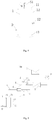
- the compressed vapor refrigeration cycle is shown in Fig. 1 , in which the horizontal coordinate denotes enthalpy values and the vertical coordinate denotes pressure values.
- the cycle is 1a-2a-3-4-5-1a at the superheat degree of 5°C, 1b-2b-3-4-5-1b at the superheat degree of 15°C, 1c-2c-3-4-5-1c at the superheat degree of 25°C, and 1d-2d-3-4-5-1d at the superheat degree of 35°C, in which the difference between the temperature at 1a, 1b, 1c, 1d and that at point 1 is the superheat degree.
- H represents enthalpy values, and a point code is used as a subscript to represent the enthalpy value at a specific point.
- HI represents the enthalpy value at point 1
- H2a represents the enthalpy value at point 2a.
- K represents the circulated mass, in which K5 represents the circulated mass of the refrigerant when the superheat degree is 5°C, K15 represents the circulated mass of the refrigerant when the superheat degree is 15°C, and so on.
- the refrigeration cycle is analyzed.
- the specific volume of the gas is increased, but the suction volume of the compressor is constant, so the circulated mass of the refrigerant is decreased, i.e. K25 ⁇ K5.
- the enthalpy difference of the refrigerating system stays the same and is still calculated according to the formula of (H1a-H5), thereby reducing Qc.
- the heating of the sucked gas will result in a decrease of the cooling quality.
- (H2c-H1c) is increased, while K25 is decreased. Therefore, P cannot be determined, and thus COPc cannot be determined, either.
- COPc also has a downward trend for most refrigerants.
- gas suction via the middle gas suction pipe S2 is needed to reduce the heating degree of the sucked gas by the motor.
- the upper gas suction pipe S1 is allowed to suck an appropriate amount of low-temperature gas to cool the motor, especially when the gas sucked via the middle gas suction pipe S2 is directly communicated with the gas suction chamber of the compressor without going through the motor.
- the performance may be lost in refrigerating conditions, it is possible that a small amount of gas still needs being sucked via the upper gas suction pipe to cool the motor in some cases like the temperature of the motor being too high or in some structural designs like the middle gas suction pipe S2 being directly communicated with the gas suction chamber of the compressor.
- the refrigerants should be sucked via the middle gas suction pipe S2 as many as possible to reduce the heating degree of the sucked gas so as to improve the performance of the compressor and the refrigerating system.
- the heating cycle is analyzed.
- the circulated mass of the refrigerant is decreased, i.e. K25 ⁇ K5
- the enthalpy difference (H2c-H4) which is used to calculate Qh is increased by (H2c-H2) compared with the benchmark cycle, i.e. (H2c-H4) is increased. Therefore, it is uncertain whether Qh improves or declines, which is determined based on different refrigerants and practical situations.
- a suitable refrigerant should be chosen to guarantee the performance of the system; especially when the system operates in a heating condition, a suitable refrigerant can be chosen to take advantage of the feature that the sucked gas is heated in the low back pressure rotary compressor to improve the heating performance of the system.
- a suitable refrigerant can be chosen so that the heating performance will not deteriorate as the superheat degree increases, such as one of R134a, R290, R410A, R161, HF0-1234yf, HFO-1234ze and so on.
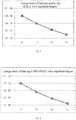
- the change trends of the heating quality and coefficient of performance can be calculated at different superheat degrees, which can be used to determine whether a refrigerant is suitable to apply in the low back pressure rotary compressor in heating conditions.
- the proportion of the gas sucked via the upper gas suction pipe S1 can be designed to adjust the superheat degree in heating conditions, which can optimize the heating quality or coefficient of performance of the refrigerating system provided with the low back pressure rotary compressor.
- the selected refrigerant should not contain too much R32 in the refrigerating system provided with the low back pressure rotary compressor.
- the calculation results are shown in Fig. 6 and Fig. 7 . It can be seen that the performance nearly reaches a critical state, so if a mixed refrigerant containing R32 is selected to apply in the refrigerating system provided with the low back pressure rotary compressor, the mass percent of R32 should be less than or equal to 50%.
- the refrigerating system and the heating system it is possible to adjust the gas suction flow distribution between the upper gas suction pipe S1 and the middle gas suction pipe S2 of the compressor to optimize the heating performance of the refrigerating system and the heating system with different types of refrigerants.
- the refrigerating system adopts a refrigerant whose heating performance obviously improves as the superheat degree rises
- the system is designed in accordance with different requirements, such as giving priority to the heating quality or coefficient of performance (COP), so as to achieve the desired effect of the system performance by adjusting the proportion of the gas sucked via the upper gas suction pipe S1.
- COP coefficient of performance
- the refrigerating system 100 provided with the low back pressure rotary compressor 1 will be described in detail herein according to two embodiments of the present invention with reference to Fig. 8 to Fig. 9 .
- the refrigerating system 100 it is possible to achieve the double objectives of optimizing the performance of the refrigerating system 100 and meeting the cooling requirement of the motor based on the above principle.
- the refrigerating system 100 includes: a low back pressure rotary compressor 1, a four-way valve 2, an outdoor heat exchanger 3, an indoor heat exchanger 5, a throttling element 4 and a control valve assembly 6.
- the refrigerating system 100 has a refrigerating mode and a heating mode.
- the low back pressure rotary compressor 1 includes a shell, a motor and a compressing mechanism.
- the shell includes an upper shell 11, a main shell 12 and a lower shell 13.
- the upper shell 11 is disposed at an upper part of the main shell 12, and the lower shell 13 is disposed at a lower part of the main shell 12.
- the upper shell 11, the main shell 12 and the lower shell 12 define an inner space of the shell, in which the motor and compressing mechanism are disposed respectively.
- An upper gas suction pipe S1 is disposed at the upper part of the shell, i.e. the upper shell 11;
- a middle gas suction pipe S2 is disposed at the middle part of the shell, i.e. the main shell 12;
- an exhaust pipe D is disposed at the shell, and in the example of Fig.
- the exhaust pipe D is disposed at the lower part of the main shell 12.
- the high pressure gas in the low back pressure rotary compressor 1 is exhausted from the exhaust pipe D, and the refrigerant that undergoes the refrigeration cycle or the heating cycle is sucked into the inner space of the shell via the upper gas suction pipe S1 and the middle gas suction pipe S2. It should be understood that the specific structure and operation mechanism of the low back pressure rotary compressor 1 are well-known to those skilled in the art, which will not be described in detail herein.
- the four-way valve 2 is formed with an exhaust valve port 20, a gas suction valve port 21, an outdoor heat exchanger valve port 22 and an indoor heat exchanger valve port 23, in which the exhaust valve port 20 is connected with the exhaust pipe D, the indoor heat exchanger valve port 23 is connected with an end of the indoor heat exchanger 5, and the outdoor heat exchanger valve port 22 is connected with an end of the outdoor heat exchanger 3.
- the refrigerating system 100 When the exhaust valve port 20 of the four-way valve 2 is communicated with the outdoor heat exchanger valve port 22 and the gas suction valve port 21 of the four-way valve 2 is communicated with the indoor heat exchanger valve port 23, the refrigerating system 100 is in the refrigerating mode; when the exhaust valve port 20 of the four-way valve 2 is communicated with the indoor heat exchanger valve port 23 and the gas suction valve port 21 of the four-way valve 2 is communicated with the outdoor heat exchanger valve port 22, the refrigerating system 100 is in the heating mode.
- an oil separator is disposed between the exhaust valve port 20 and the exhaust pipe D to conduct oil-gas separation of the refrigerant exhausted from the exhaust pipe D.
- the structure and operation mechanism of the oil separator are well-known to those skilled in the art, which will not be described in detail herein.
- the other end of the indoor heat exchanger 5 is connected with the other end of the outdoor heat exchanger 3.
- the throttling element 4 is connected between the outdoor heat exchanger 3 and the indoor heat exchanger 5 in series.
- the throttling element 4 is a capillary or an electromagnetic valve.
- the control valve assembly 6 is connected with the gas suction valve port 21, the upper gas suction pipe S1 and the middle gas suction pipe S2 via a first pipeline G, a second pipeline F and a third pipeline E respectively.
- the control valve assembly 6 is connected with the gas suction valve port 21 via the first pipeline G, connected with the upper gas suction pipe S1 via the second pipeline F and connected with the middle gas suction pipe S2 via the third pipeline E.
- the control valve assembly 6 has a function of determining the operation mode (the refrigerating mode or the heating mode) of the refrigerating system 100, and the control valve assembly 6 controls the gas suction flows of the second pipeline F and the third pipeline E based on the operation mode of the refrigerating system 100.
- the control valve assembly 6 includes a first control valve and a second control valve disposed at the second pipeline F and the third pipeline E respectively, in which case, the gas suction flows of the second pipeline F and the third pipeline E can be controlled by controlling the size of the openings of the first control valve and the second control valve or the position of the valve core.
- the present invention is not limited thereby. According to the invention, the control valve assembly 6 achieves the objective of controlling the gas suction flows of the second pipeline F and the third pipeline E by controlling the diameter ratio or the flow area ratio of the second pipeline F and the third pipeline E.
- the indoor heat exchanger 5 is a low pressure side heat exchanger and the outdoor heat exchanger 3 is a high pressure side heat exchanger.
- the high temperature and high pressure gas exhausted from the exhaust pipe D flows into the outdoor heat exchanger 3 for condensation and heat exchange by means of the flow direction control of the four-way valve 2, and then flows into the indoor heat exchanger 5 for cooling the indoor environment by means of the throttling function of the throttling element 4.
- the low temperature and low pressure return gas of the system exhausted from the outlet of the indoor heat exchanger 5 flows to the control valve assembly 6 via the first pipeline G.
- the control valve assembly 6 controls the gas suction flow of the third pipeline E to be larger than that of the second pipeline F.
- the control valve assembly 6 makes the return gas of the system mainly flow to the direction of the middle gas suction pipe S2.
- the total flow of the return gas of the system is the gas suction flow of the first pipeline G, i.e. v
- the flow into the middle gas suction pipe S2 is the gas suction flow of the third pipeline E, i.e. v2.
- the ratio between v2 and the total flow v is v3, and v3 is greater than or equal to 0,6.
- v2 can be equal to v, i.e. the gas suction flow of the third pipeline E is equal to that of the first pipeline G, in which case the gas suction is entirely conducted via the middle gas suction pipe S2.
- the gas is mainly sucked via the middle gas suction pipe S2 without going through the motor, thereby reducing the heating degree of the sucked gas by the motor and the deterioration of the performance due to heating. Meanwhile, a small amount of gas is sucked via the upper gas suction pipe S1, and cools the motor after going through the motor so as to guarantee the reliability of the motor. In certain use conditions, even though no gas suction is conducted via the upper gas suction pipe S1, the temperature of the motor will not rise to a higher level due to the low-temperature environment.
- the gas is entirely sucked via the middle gas suction pipe S2, so as to furthest avoid the deterioration of the performance due to the heating of the sucked gas and to improve the performance of the low back pressure rotary compressor 1 and the refrigerating system 100.
- the indoor heat exchanger 5 is a high pressure side heat exchanger and the outdoor heat exchanger 3 is a low pressure side heat exchanger.
- the high temperature and high pressure gas exhausted from the exhaust pipe D flows into the indoor heat exchanger 5 for heating the indoor environment by means of the flow direction control of the four-way valve 2, then flows into the outdoor heat exchanger 3 for heat exchange with the outside air by means of the throttling function of the throttling element 4, and finally the low temperature and low pressure return gas of the system exhausted from the outlet of the outdoor heat exchanger 3 flows to the control valve assembly 6 via the first pipeline G.
- the control valve assembly 6 controls the gas suction flow of the second pipeline F to be larger than that of the third pipeline E.
- the control valve assembly 6 makes the return gas of the system mainly flow to the direction of the upper gas suction pipe S1.
- the total flow of the return gas of the system is the gas suction flow of the first pipeline G, i.e. v
- the flow into the upper gas suction pipe S1 is the gas suction flow of the second pipeline F, i.e. v1.
- the ratio between v1 and the total flow v is v4, and v4 is greater than or equal to 0.6.
- v1 can be equal to v, i.e. the gas suction flow of the second pipeline F is equal to that of the first pipeline G, in which case the gas suction is entirely conducted via the upper gas suction pipe S1.
- the control valve assembly 6 controls the gas suction flow of the third pipeline E to be larger than that of the second pipeline F; when the refrigerating system is in the heating mode, the control valve assembly 6 controls the gas suction flow of the second pipeline F to be larger than that of the third pipeline E. Therefore, when the refrigerating system 100 is in the refrigerating mode, the gas is mainly sucked via the middle gas suction pipe S2 without going through the motor, thereby reducing the heating degree of the sucked gas by the motor and the deterioration of the performance due to heating.
- gas suction is mainly conducted via the upper gas suction pipe S1 and the sucked gas cools the motor after going through the motor so as to maximize the reliability of the motor.
- the control valve assembly 6 is connected with the four-way valve 2 to determine whether the refrigerating system 100 is in the refrigerating mode or the heating mode in accordance with the flow direction of the refrigerant in the four-way valve 2. Specifically, as shown in Fig. 9 , the control valve assembly 6 monitors the flow direction of the refrigerant in the four-way valve 2 via a channel L.
- the present invention is not limited thereby.
- the control valve assembly 6 can determine the operation mode of the refrigerating system 100 by other means, such as by means of remote signals from the refrigerating system 100.
- the refrigerant adopted in the refrigerating system 100 has the following property: when the evaporation temperature, condensation temperature and supercooling degree are constant, the heating quality or coefficient of performance of the refrigerant in the low back pressure rotary compressor 1 improves as the superheat degree rises.
- the heating quality or coefficient of performance has an upward trend as the superheat degree rises from 5°C to 35°C.
- the refrigerant is one of R290, R134a and R410A.
- the refrigerating system 100 includes: a low back pressure rotary compressor 1, an outdoor heat exchanger 3, an indoor heat exchanger 5, a throttling element 4 and a control valve assembly 6.
- the refrigerating system 100 can only operate in a refrigerating mode. In other words, the refrigerating system 100 is only a cooler.
- the low back pressure rotary compressor 1 includes a shell, and a motor and a compressing mechanism disposed in the shell, an upper gas suction pipe S1 is disposed at an upper part of the shell, a middle gas suction pipe S2 is disposed at a middle part of the shell, and an exhaust pipe D is disposed at the shell. It should be noted that the specific structure and operation mechanism of the low back pressure rotary compressor 1 are well-known to those skilled in the art, which will not be described in detail herein.
- An end of the outdoor heat exchanger 3 is connected with the exhaust pipe D.
- An end of the indoor heat exchanger 5 is connected with the other end of the outdoor heat exchanger 3.
- the throttling element 4 is connected between the outdoor heat exchanger 3 and the indoor heat exchanger 5 in series.
- the throttling element 4 is a capillary or an electromagnetic valve.
- the control valve assembly 6 is connected with the other end of the indoor heat exchanger 5, the upper gas suction pipe S1 and the middle gas suction pipe S2 via a first pipeline G, a second pipeline F and a third pipeline E respectively.
- the control valve assembly 6 is connected with the other end of the indoor heat exchanger 5 via the first pipeline G, connected with the upper gas suction pipe S1 via the second pipeline F and connected with the middle gas suction pipe S2 via the third pipeline E.
- the control valve assembly 6 controls the gas suction flow of the third pipeline E to be larger than that of the second pipeline F.
- control valve assembly 6 may be a three-way valve or include valve bodies disposed at the second pipeline F and the third pipeline E respectively, in which case, the gas suction flows of the second pipeline F and the third pipeline E can be controlled by controlling the cross-sectional areas of the second pipeline F and the third pipeline E.
- the indoor heat exchanger 5 When the refrigerating system 100 is in operation, the indoor heat exchanger 5 always operates as a low pressure side heat exchanger and the outdoor heat exchanger 3 always operates as a high pressure side heat exchanger.
- the high temperature and high pressure gas exhausted from the compressor flows into the outdoor heat exchanger 3 for condensation, and then flows into the indoor heat exchanger 5 after passing through the throttling element 4 for evaporation to achieve the purpose of refrigerating.
- the flow of the return gas of the system flowing from the indoor heat exchanger 5 is v and the gas flows into the control valve assembly 6.
- the return gas of the system is mainly sucked via the middle gas suction pipe S2.
- the ratio between the gas suction flow v2 of the third pipeline E and the gas suction flow v of the first pipeline G is v3, and v3 is greater than or equal to 0.6.
- v2 can be equal to v, i.e. the gas suction flow of the third pipeline E is equal to that of the first pipeline G, in which case the gas suction is entirely conducted via the middle gas suction pipe S2.
- the control valve assembly 6 controls the gas suction flow of the third pipeline E to be larger than that of the second pipeline F, and the gas is mainly sucked via the middle gas suction pipe S2 without going through the motor, thereby reducing the heating degree of the sucked gas by the motor and the deterioration of the performance due to heating. Meanwhile, a small amount of gas is sucked via the upper gas suction pipe S1, and cools the motor after going through the motor so as to guarantee the reliability of the motor. In certain use conditions, even though no gas suction is conducted via the upper gas suction pipe S1, the temperature of the motor will not rise to a higher level due to the low-temperature environment. In this case, it is allowable that the gas is entirely sucked via the middle gas suction pipe S2, so as to furthest avoid the deterioration of the performance due to the heating of the sucked gas and to improve the performance of the compressor and the system.
- the refrigerant adopted in the refrigerating system 100 has the following property: when the evaporation temperature, condensation temperature and supercooling degree are constant, the heating quality or coefficient of performance of the refrigerant in the low back pressure rotary compressor 1 improves as the superheat degree rises.
- the heating quality or coefficient of performance has an upward trend as the superheat degree rises from 5°C to 35°C.
- the refrigerant is one of R290, R134a and R410A.
- the heating system 200 provided with the low back pressure rotary compressor 1 according to embodiments of the present invention will be described in detail herein with reference to Fig. 8 .
- the heating system 200 it is possible to optimize the heating quality or coefficient of performance of the heating system 200 in the heating mode based on the above principle.
- the heating system 200 includes a low back pressure rotary compressor 1, an indoor heat exchanger 5, an outdoor heat exchanger 3, a throttling element 4 and a control valve assembly 6.
- the heating system 200 can only operate in a heating mode.
- the heating system 200 is a heat pump water heater and the indoor heat exchanger 5 is disposed in a water tank 9 to heat water in the water tank 9.
- An end of the indoor heat exchanger 5 is connected with the exhaust pipe D.
- An end of the outdoor heat exchanger 3 is connected with the other end of the indoor heat exchanger 5.
- the throttling element 4 is connected between the indoor heat exchanger 5 and the outdoor heat exchanger 3 in series.
- the throttling element 4 is a capillary or an electromagnetic valve.
- the control valve assembly 6 is connected with the outdoor heat exchanger 3, the upper gas suction pipe S1 and the middle gas suction pipe S2 via a first pipeline G, a second pipeline F and a third pipeline E respectively.
- the control valve assembly 6 is connected with the outdoor heat exchanger 3 via the first pipeline G, connected with the upper gas suction pipe S1 via the second pipeline F and connected with the middle gas suction pipe S2 via the third pipeline E.
- the control valve assembly 6 can control the gas suction flows of the second pipeline F and the third pipeline E, and the control valve assembly 6 controls the gas suction flow of the second pipeline F to be larger than that of the third pipeline E.
- control valve assembly 6 may be a three-way valve or include valve bodies disposed at the second pipeline F and the third pipeline E respectively, in which case, the gas suction flows of the second pipeline F and the third pipeline E can be controlled by controlling the cross-sectional areas of the second pipeline F and the third pipeline E.
- the outdoor heat exchanger 3 is a low pressure side heat exchanger and the indoor heat exchanger 5 is a high pressure side heat exchanger.
- the high temperature and high pressure gas exhausted from the exhaust pipe D flows into the indoor heat exchanger 5 to heat water in the water tank 9 or heat the indoor environment, then flows into the outdoor heat exchanger 3 for heat exchange with the outside air by means of the throttling function of the throttling element 4, and finally the low temperature and low pressure return gas of the system exhausted from the outlet of the outdoor heat exchanger 3 flows to the control valve assembly 6.
- the control valve assembly 6 controls the gas suction flow of the second pipeline F to be larger than that of the third pipeline E.
- the control valve assembly 6 makes the return gas of the system mainly flow to the direction of the upper gas suction pipe S1.
- the total flow of the return gas of the system is v
- the flow into the upper gas suction pipe S1 is v1, i.e. the gas suction flow of the second pipeline F.
- the ratio between v1 and the total flow v is v4, and v4 is greater than or equal to 0.8.
- v1 can be equal to v, i.e. the gas suction flow of the second pipeline F is equal to that of the first pipeline G, in which case the gas suction is entirely conducted via the upper gas suction pipe S1.
- control valve assembly 6 controls the gas suction flow of the second pipeline F to be larger than that of the third pipeline E, so that the sucked gas goes through the motor to cool the motor so as to maximize the reliability of the motor.
- the refrigerant in the low back pressure rotary compressor 1 is a mixed refrigerant containing R32 with a mass percent less than or equal to 50%.
Landscapes
- Engineering & Computer Science (AREA)
- Physics & Mathematics (AREA)
- Mechanical Engineering (AREA)
- Thermal Sciences (AREA)
- General Engineering & Computer Science (AREA)
- Applications Or Details Of Rotary Compressors (AREA)
- Compression-Type Refrigeration Machines With Reversible Cycles (AREA)
Claims (6)
- Système de réfrigération (100) comportant :un compresseur rotatif à faible contre pression (1) comportant une coque, et un moteur et un mécanisme de compression disposés dans la coque respectivement, une conduite d'aspiration de gaz supérieure (SI) qui est disposée au niveau d'une partie supérieure de la coque pour aspirer du gaz au travers du moteur, une conduite d'aspiration de gaz intermédiaire (S2) qui est disposée au niveau d'une partie intermédiaire de la coque, et une conduite d'échappement (D) qui est disposée au niveau de la coque ;une soupape à quatre voies (2) formée avec un orifice de soupape d'échappement (20), un orifice de soupape d'aspiration de gaz (21), un orifice de soupape d'échangeur de chaleur extérieur (22) et un orifice de soupape d'échangeur de chaleur intérieur (23), l'orifice de soupape d'échappement (20) étant raccordé à la conduite d'échappement (D) ;un échangeur de chaleur extérieur (3) définissant une extrémité raccordée à l'orifice de soupape d'échangeur de chaleur extérieur (22) ;un échangeur de chaleur intérieur (5) définissant une extrémité raccordée à l'orifice de soupape d'échangeur de chaleur intérieur (23), et l'autre extrémité raccordée à l'autre extrémité de l'échangeur de chaleur extérieur (3) ;un élément d'étranglement (4) raccordé entre l'échangeur de chaleur extérieur (3) et l'échangeur de chaleur intérieur (5) en série,le système de réfrigération étant caractérisé en ce que le système de réfrigération (100) comporte par ailleurs un ensemble formant soupape de régulation (6) configuré pour déterminer un mode de fonctionnement du système de réfrigération, l'ensemble formant soupape de régulation (6) étant raccordé à l'orifice de soupape d'aspiration de gaz (21), à la conduite d'aspiration de gaz supérieure (SI) et à la conduite d'aspiration de gaz intermédiaire (S2) par le biais d'une première canalisation (G), d'une deuxième canalisation (F) et d'une troisième canalisation (E) respectivement, la deuxième canalisation (F) étant raccordée à la conduite d'aspiration de gaz supérieure (SI) et la troisième canalisation (E) étant raccordée à la conduite d'aspiration de gaz intermédiaire (S2), et dans lequel, quand l'ensemble formant soupape de régulation (6) détermine que le système de réfrigération est en mode de réfrigération, l'ensemble formant soupape de régulation (6) est configuré pour réguler un débit d'aspiration de gaz de la troisième canalisation (E) pour qu'il soit supérieur par rapport à celui de la deuxième canalisation (F) ; quand l'ensemble formant soupape de régulation (6) détermine que le système de réfrigération est en mode de chauffage, l'ensemble formant soupape de régulation (6) est configuré pour réguler le débit d'aspiration de gaz de la deuxième canalisation (F) pour qu'il soit supérieur par rapport à celui de la troisième canalisation (E), de ce fait l'ensemble formant soupape de régulation (6) peut réaliser l'objectif de régulation des débits d'aspiration de gaz de la deuxième canalisation (F) et de la troisième canalisation (E) en régulant le rapport des diamètres ou le rapport des sections de débit de la deuxième canalisation F et de la troisième canalisation (E).
- Système de réfrigération (100) selon la revendication 1, dans lequel, en mode de réfrigération, un rapport entre le débit d'aspiration de gaz de la troisième canalisation (E) et celui de la première canalisation (G) est supérieur ou égal à 0,6, de préférence le débit d'aspiration de gaz de la troisième canalisation (E) est égal à celui de la première canalisation (G).
- Système de réfrigération (100) selon la revendication 1, dans lequel, en mode de chauffage, un rapport entre le débit d'aspiration de gaz de la deuxième canalisation (F) et celui de la première canalisation (G) est supérieur ou égal à 0,6, de préférence, le débit d'aspiration de gaz de la deuxième canalisation (F) est égal à celui de la première canalisation (G).
- Système de réfrigération (100) selon l'une quelconque des revendications 1 à 3, dans lequel l'ensemble formant soupape de régulation (6) comporte une première soupape de régulation et une deuxième soupape de régulation disposées au niveau de la deuxième canalisation (F) et de la troisième canalisation (E) respectivement.
- Système de réfrigération (100) selon l'une quelconque des revendications 1 à 4, dans lequel l'ensemble formant soupape de régulation (6) est raccordé à la soupape à quatre voies (2) pour déterminer si le système de réfrigération est en mode de réfrigération ou en mode de chauffage en fonction d'une direction du débit d'un fluide frigorigène dans la soupape à quatre voies (2).
- Système de réfrigération (100) selon l'une quelconque des revendications 1 à 5, dans lequel, quand une température d'évaporation, une température de condensation et un degré de sous-refroidissement sont constants, une qualité de chauffage ou coefficient de performance d'un fluide frigorigène dans le compresseur rotatif à faible contre pression (1) augmente au fur et à mesure qu'un degré de surchauffe augmente.
Applications Claiming Priority (1)
| Application Number | Priority Date | Filing Date | Title |
|---|---|---|---|
| PCT/CN2013/084749 WO2015042970A1 (fr) | 2013-09-30 | 2013-09-30 | Système de refroidissement et système de chauffage |
Publications (3)
| Publication Number | Publication Date |
|---|---|
| EP2977691A1 EP2977691A1 (fr) | 2016-01-27 |
| EP2977691A4 EP2977691A4 (fr) | 2016-06-08 |
| EP2977691B1 true EP2977691B1 (fr) | 2021-09-08 |
Family
ID=52741890
Family Applications (1)
| Application Number | Title | Priority Date | Filing Date |
|---|---|---|---|
| EP13881452.0A Active EP2977691B1 (fr) | 2013-09-30 | 2013-09-30 | Système de refroidissement et système de chauffage |
Country Status (2)
| Country | Link |
|---|---|
| EP (1) | EP2977691B1 (fr) |
| WO (1) | WO2015042970A1 (fr) |
Families Citing this family (1)
| Publication number | Priority date | Publication date | Assignee | Title |
|---|---|---|---|---|
| CN109690209B (zh) * | 2016-09-12 | 2021-05-07 | 三菱电机株式会社 | 空调装置 |
Family Cites Families (10)
| Publication number | Priority date | Publication date | Assignee | Title |
|---|---|---|---|---|
| JPH08247060A (ja) * | 1995-03-15 | 1996-09-24 | Toshiba Corp | ロータリコンプレッサ |
| KR20050072299A (ko) * | 2004-01-06 | 2005-07-11 | 삼성전자주식회사 | 냉난방 공기조화시스템 |
| CN101341367A (zh) * | 2005-12-16 | 2009-01-07 | 开利公司 | 具有脉宽调制控制器的热泵 |
| CN100529406C (zh) * | 2007-11-09 | 2009-08-19 | 广东美芝制冷设备有限公司 | 壳体低压的旋转式压缩机及其冷媒、回油的控制方式和应用 |
| JP5611353B2 (ja) * | 2010-07-29 | 2014-10-22 | 三菱電機株式会社 | ヒートポンプ |
| US20120055185A1 (en) * | 2010-09-02 | 2012-03-08 | Ran Luo | Refrigeration apparatus |
| CN102678572B (zh) * | 2011-03-16 | 2015-02-18 | 珠海格力电器股份有限公司 | 空调及其电机预冷的低背压压缩机 |
| CN202182584U (zh) * | 2011-06-24 | 2012-04-04 | 大连三洋压缩机有限公司 | 降低吸气无效过热的压缩机及其制冷系统 |
| CN202393113U (zh) * | 2011-11-03 | 2012-08-22 | 广东美芝制冷设备有限公司 | 制冷装置 |
| CN103557646B (zh) * | 2013-09-30 | 2015-11-18 | 广东美芝制冷设备有限公司 | 制冷系统和制热系统 |
-
2013
- 2013-09-30 WO PCT/CN2013/084749 patent/WO2015042970A1/fr active Application Filing
- 2013-09-30 EP EP13881452.0A patent/EP2977691B1/fr active Active
Also Published As
| Publication number | Publication date |
|---|---|
| AU2013383644B2 (en) | 2016-03-17 |
| AU2013383644A1 (en) | 2015-04-16 |
| EP2977691A4 (fr) | 2016-06-08 |
| EP2977691A1 (fr) | 2016-01-27 |
| AU2013383644A8 (en) | 2016-04-21 |
| WO2015042970A1 (fr) | 2015-04-02 |
Similar Documents
| Publication | Publication Date | Title |
|---|---|---|
| JP6257801B2 (ja) | 冷凍サイクル装置及び冷凍サイクル装置の異常検知システム | |
| US9360226B2 (en) | Heat pump system | |
| JP5847366B1 (ja) | 空気調和装置 | |
| US11199342B2 (en) | Air conditioner | |
| WO2014192140A1 (fr) | Climatiseur | |
| US20140230477A1 (en) | Hot water supply air conditioning system | |
| EP2416093A1 (fr) | Système combiné composé d'un dispositif de climatisation et d'un dispositif d'alimentation en eau chaude | |
| EP2532983A2 (fr) | Chaudière à pompe à chaleur et procédé de commande associé | |
| EP3492839A1 (fr) | Dispositif à cycle de réfrigération | |
| JP2019020112A (ja) | 空調システム | |
| US9816736B2 (en) | Air-conditioning apparatus | |
| WO2016208042A1 (fr) | Dispositif de climatisation | |
| JP5681787B2 (ja) | 2元冷凍サイクル装置 | |
| JP2012052767A (ja) | ヒートポンプ装置 | |
| CN113439188B (zh) | 空调装置 | |
| JPWO2015125219A1 (ja) | 空気調和装置 | |
| JP2012180970A (ja) | 冷凍サイクル装置 | |
| JP2016133257A (ja) | 空気調和装置 | |
| EP2977691B1 (fr) | Système de refroidissement et système de chauffage | |
| JP2017116155A (ja) | 空気調和装置 | |
| AU2013383644B8 (en) | Refrigerating system and heating system | |
| CN111076445A (zh) | 空调系统及其运行方法 | |
| JP6393973B2 (ja) | 冷凍装置 | |
| WO2023243517A1 (fr) | Dispositif de climatisation | |
| WO2023158583A1 (fr) | Systèmes de pompe à chaleur avec pompe à chaleur d'appoint |
Legal Events
| Date | Code | Title | Description |
|---|---|---|---|
| PUAI | Public reference made under article 153(3) epc to a published international application that has entered the european phase |
Free format text: ORIGINAL CODE: 0009012 |
|
| 17P | Request for examination filed |
Effective date: 20150421 |
|
| AK | Designated contracting states |
Kind code of ref document: A1 Designated state(s): AL AT BE BG CH CY CZ DE DK EE ES FI FR GB GR HR HU IE IS IT LI LT LU LV MC MK MT NL NO PL PT RO RS SE SI SK SM TR |
|
| AX | Request for extension of the european patent |
Extension state: BA ME |
|
| A4 | Supplementary search report drawn up and despatched |
Effective date: 20160506 |
|
| RIC1 | Information provided on ipc code assigned before grant |
Ipc: F25B 13/00 20060101ALI20160429BHEP Ipc: F25B 41/04 20060101AFI20160429BHEP Ipc: F25B 1/04 20060101ALI20160429BHEP Ipc: F04C 29/04 20060101ALI20160429BHEP Ipc: F25B 31/00 20060101ALI20160429BHEP |
|
| DAX | Request for extension of the european patent (deleted) | ||
| STAA | Information on the status of an ep patent application or granted ep patent |
Free format text: STATUS: EXAMINATION IS IN PROGRESS |
|
| 17Q | First examination report despatched |
Effective date: 20180903 |
|
| STAA | Information on the status of an ep patent application or granted ep patent |
Free format text: STATUS: EXAMINATION IS IN PROGRESS |
|
| REG | Reference to a national code |
Ref country code: DE Ref legal event code: R079 Ref document number: 602013079219 Country of ref document: DE Free format text: PREVIOUS MAIN CLASS: F25B0041040000 Ipc: F25B0041200000 |
|
| GRAP | Despatch of communication of intention to grant a patent |
Free format text: ORIGINAL CODE: EPIDOSNIGR1 |
|
| STAA | Information on the status of an ep patent application or granted ep patent |
Free format text: STATUS: GRANT OF PATENT IS INTENDED |
|
| RIC1 | Information provided on ipc code assigned before grant |
Ipc: F25B 1/04 20060101ALI20210525BHEP Ipc: F25B 13/00 20060101ALI20210525BHEP Ipc: F25B 31/00 20060101ALI20210525BHEP Ipc: F04C 29/04 20060101ALI20210525BHEP Ipc: F25B 41/20 20210101AFI20210525BHEP |
|
| INTG | Intention to grant announced |
Effective date: 20210614 |
|
| GRAS | Grant fee paid |
Free format text: ORIGINAL CODE: EPIDOSNIGR3 |
|
| GRAA | (expected) grant |
Free format text: ORIGINAL CODE: 0009210 |
|
| STAA | Information on the status of an ep patent application or granted ep patent |
Free format text: STATUS: THE PATENT HAS BEEN GRANTED |
|
| AK | Designated contracting states |
Kind code of ref document: B1 Designated state(s): AL AT BE BG CH CY CZ DE DK EE ES FI FR GB GR HR HU IE IS IT LI LT LU LV MC MK MT NL NO PL PT RO RS SE SI SK SM TR |
|
| REG | Reference to a national code |
Ref country code: GB Ref legal event code: FG4D |
|
| REG | Reference to a national code |
Ref country code: CH Ref legal event code: EP Ref country code: AT Ref legal event code: REF Ref document number: 1428930 Country of ref document: AT Kind code of ref document: T Effective date: 20210915 |
|
| REG | Reference to a national code |
Ref country code: DE Ref legal event code: R096 Ref document number: 602013079219 Country of ref document: DE |
|
| REG | Reference to a national code |
Ref country code: IE Ref legal event code: FG4D |
|
| REG | Reference to a national code |
Ref country code: LT Ref legal event code: MG9D |
|
| REG | Reference to a national code |
Ref country code: NL Ref legal event code: MP Effective date: 20210908 |
|
| PG25 | Lapsed in a contracting state [announced via postgrant information from national office to epo] |
Ref country code: SE Free format text: LAPSE BECAUSE OF FAILURE TO SUBMIT A TRANSLATION OF THE DESCRIPTION OR TO PAY THE FEE WITHIN THE PRESCRIBED TIME-LIMIT Effective date: 20210908 Ref country code: RS Free format text: LAPSE BECAUSE OF FAILURE TO SUBMIT A TRANSLATION OF THE DESCRIPTION OR TO PAY THE FEE WITHIN THE PRESCRIBED TIME-LIMIT Effective date: 20210908 Ref country code: HR Free format text: LAPSE BECAUSE OF FAILURE TO SUBMIT A TRANSLATION OF THE DESCRIPTION OR TO PAY THE FEE WITHIN THE PRESCRIBED TIME-LIMIT Effective date: 20210908 Ref country code: BG Free format text: LAPSE BECAUSE OF FAILURE TO SUBMIT A TRANSLATION OF THE DESCRIPTION OR TO PAY THE FEE WITHIN THE PRESCRIBED TIME-LIMIT Effective date: 20211208 Ref country code: LT Free format text: LAPSE BECAUSE OF FAILURE TO SUBMIT A TRANSLATION OF THE DESCRIPTION OR TO PAY THE FEE WITHIN THE PRESCRIBED TIME-LIMIT Effective date: 20210908 Ref country code: NO Free format text: LAPSE BECAUSE OF FAILURE TO SUBMIT A TRANSLATION OF THE DESCRIPTION OR TO PAY THE FEE WITHIN THE PRESCRIBED TIME-LIMIT Effective date: 20211208 Ref country code: ES Free format text: LAPSE BECAUSE OF FAILURE TO SUBMIT A TRANSLATION OF THE DESCRIPTION OR TO PAY THE FEE WITHIN THE PRESCRIBED TIME-LIMIT Effective date: 20210908 Ref country code: FI Free format text: LAPSE BECAUSE OF FAILURE TO SUBMIT A TRANSLATION OF THE DESCRIPTION OR TO PAY THE FEE WITHIN THE PRESCRIBED TIME-LIMIT Effective date: 20210908 |
|
| REG | Reference to a national code |
Ref country code: AT Ref legal event code: MK05 Ref document number: 1428930 Country of ref document: AT Kind code of ref document: T Effective date: 20210908 |
|
| PG25 | Lapsed in a contracting state [announced via postgrant information from national office to epo] |
Ref country code: LV Free format text: LAPSE BECAUSE OF FAILURE TO SUBMIT A TRANSLATION OF THE DESCRIPTION OR TO PAY THE FEE WITHIN THE PRESCRIBED TIME-LIMIT Effective date: 20210908 Ref country code: GR Free format text: LAPSE BECAUSE OF FAILURE TO SUBMIT A TRANSLATION OF THE DESCRIPTION OR TO PAY THE FEE WITHIN THE PRESCRIBED TIME-LIMIT Effective date: 20211209 |
|
| PG25 | Lapsed in a contracting state [announced via postgrant information from national office to epo] |
Ref country code: AT Free format text: LAPSE BECAUSE OF FAILURE TO SUBMIT A TRANSLATION OF THE DESCRIPTION OR TO PAY THE FEE WITHIN THE PRESCRIBED TIME-LIMIT Effective date: 20210908 |
|
| REG | Reference to a national code |
Ref country code: CH Ref legal event code: PL |
|
| REG | Reference to a national code |
Ref country code: BE Ref legal event code: MM Effective date: 20210930 |
|
| PG25 | Lapsed in a contracting state [announced via postgrant information from national office to epo] |
Ref country code: IS Free format text: LAPSE BECAUSE OF FAILURE TO SUBMIT A TRANSLATION OF THE DESCRIPTION OR TO PAY THE FEE WITHIN THE PRESCRIBED TIME-LIMIT Effective date: 20220108 Ref country code: SM Free format text: LAPSE BECAUSE OF FAILURE TO SUBMIT A TRANSLATION OF THE DESCRIPTION OR TO PAY THE FEE WITHIN THE PRESCRIBED TIME-LIMIT Effective date: 20210908 Ref country code: SK Free format text: LAPSE BECAUSE OF FAILURE TO SUBMIT A TRANSLATION OF THE DESCRIPTION OR TO PAY THE FEE WITHIN THE PRESCRIBED TIME-LIMIT Effective date: 20210908 Ref country code: RO Free format text: LAPSE BECAUSE OF FAILURE TO SUBMIT A TRANSLATION OF THE DESCRIPTION OR TO PAY THE FEE WITHIN THE PRESCRIBED TIME-LIMIT Effective date: 20210908 Ref country code: PT Free format text: LAPSE BECAUSE OF FAILURE TO SUBMIT A TRANSLATION OF THE DESCRIPTION OR TO PAY THE FEE WITHIN THE PRESCRIBED TIME-LIMIT Effective date: 20220110 Ref country code: PL Free format text: LAPSE BECAUSE OF FAILURE TO SUBMIT A TRANSLATION OF THE DESCRIPTION OR TO PAY THE FEE WITHIN THE PRESCRIBED TIME-LIMIT Effective date: 20210908 Ref country code: NL Free format text: LAPSE BECAUSE OF FAILURE TO SUBMIT A TRANSLATION OF THE DESCRIPTION OR TO PAY THE FEE WITHIN THE PRESCRIBED TIME-LIMIT Effective date: 20210908 Ref country code: EE Free format text: LAPSE BECAUSE OF FAILURE TO SUBMIT A TRANSLATION OF THE DESCRIPTION OR TO PAY THE FEE WITHIN THE PRESCRIBED TIME-LIMIT Effective date: 20210908 Ref country code: CZ Free format text: LAPSE BECAUSE OF FAILURE TO SUBMIT A TRANSLATION OF THE DESCRIPTION OR TO PAY THE FEE WITHIN THE PRESCRIBED TIME-LIMIT Effective date: 20210908 Ref country code: AL Free format text: LAPSE BECAUSE OF FAILURE TO SUBMIT A TRANSLATION OF THE DESCRIPTION OR TO PAY THE FEE WITHIN THE PRESCRIBED TIME-LIMIT Effective date: 20210908 |
|
| REG | Reference to a national code |
Ref country code: DE Ref legal event code: R097 Ref document number: 602013079219 Country of ref document: DE |
|
| PG25 | Lapsed in a contracting state [announced via postgrant information from national office to epo] |
Ref country code: MC Free format text: LAPSE BECAUSE OF FAILURE TO SUBMIT A TRANSLATION OF THE DESCRIPTION OR TO PAY THE FEE WITHIN THE PRESCRIBED TIME-LIMIT Effective date: 20210908 |
|
| PLBE | No opposition filed within time limit |
Free format text: ORIGINAL CODE: 0009261 |
|
| STAA | Information on the status of an ep patent application or granted ep patent |
Free format text: STATUS: NO OPPOSITION FILED WITHIN TIME LIMIT |
|
| PG25 | Lapsed in a contracting state [announced via postgrant information from national office to epo] |
Ref country code: LU Free format text: LAPSE BECAUSE OF NON-PAYMENT OF DUE FEES Effective date: 20210930 Ref country code: IE Free format text: LAPSE BECAUSE OF NON-PAYMENT OF DUE FEES Effective date: 20210930 Ref country code: DK Free format text: LAPSE BECAUSE OF FAILURE TO SUBMIT A TRANSLATION OF THE DESCRIPTION OR TO PAY THE FEE WITHIN THE PRESCRIBED TIME-LIMIT Effective date: 20210908 Ref country code: BE Free format text: LAPSE BECAUSE OF NON-PAYMENT OF DUE FEES Effective date: 20210930 |
|
| 26N | No opposition filed |
Effective date: 20220609 |
|
| GBPC | Gb: european patent ceased through non-payment of renewal fee |
Effective date: 20211208 |
|
| PG25 | Lapsed in a contracting state [announced via postgrant information from national office to epo] |
Ref country code: SI Free format text: LAPSE BECAUSE OF FAILURE TO SUBMIT A TRANSLATION OF THE DESCRIPTION OR TO PAY THE FEE WITHIN THE PRESCRIBED TIME-LIMIT Effective date: 20210908 Ref country code: LI Free format text: LAPSE BECAUSE OF NON-PAYMENT OF DUE FEES Effective date: 20210930 Ref country code: CH Free format text: LAPSE BECAUSE OF NON-PAYMENT OF DUE FEES Effective date: 20210930 |
|
| PG25 | Lapsed in a contracting state [announced via postgrant information from national office to epo] |
Ref country code: GB Free format text: LAPSE BECAUSE OF NON-PAYMENT OF DUE FEES Effective date: 20211208 |
|
| PG25 | Lapsed in a contracting state [announced via postgrant information from national office to epo] |
Ref country code: IT Free format text: LAPSE BECAUSE OF FAILURE TO SUBMIT A TRANSLATION OF THE DESCRIPTION OR TO PAY THE FEE WITHIN THE PRESCRIBED TIME-LIMIT Effective date: 20210908 |
|
| PG25 | Lapsed in a contracting state [announced via postgrant information from national office to epo] |
Ref country code: HU Free format text: LAPSE BECAUSE OF FAILURE TO SUBMIT A TRANSLATION OF THE DESCRIPTION OR TO PAY THE FEE WITHIN THE PRESCRIBED TIME-LIMIT; INVALID AB INITIO Effective date: 20130930 |
|
| PG25 | Lapsed in a contracting state [announced via postgrant information from national office to epo] |
Ref country code: CY Free format text: LAPSE BECAUSE OF FAILURE TO SUBMIT A TRANSLATION OF THE DESCRIPTION OR TO PAY THE FEE WITHIN THE PRESCRIBED TIME-LIMIT Effective date: 20210908 |
|
| PGFP | Annual fee paid to national office [announced via postgrant information from national office to epo] |
Ref country code: FR Payment date: 20230919 Year of fee payment: 11 Ref country code: DE Payment date: 20230919 Year of fee payment: 11 |