EP2977163A1 - Concrete mixture measurement sensor, system and method - Google Patents
Concrete mixture measurement sensor, system and method Download PDFInfo
- Publication number
- EP2977163A1 EP2977163A1 EP15180076.0A EP15180076A EP2977163A1 EP 2977163 A1 EP2977163 A1 EP 2977163A1 EP 15180076 A EP15180076 A EP 15180076A EP 2977163 A1 EP2977163 A1 EP 2977163A1
- Authority
- EP
- European Patent Office
- Prior art keywords
- sensor
- concrete
- mixer
- axis
- control circuit
- Prior art date
- Legal status (The legal status is an assumption and is not a legal conclusion. Google has not performed a legal analysis and makes no representation as to the accuracy of the status listed.)
- Granted
Links
- 239000000203 mixture Substances 0.000 title claims abstract description 131
- 238000000034 method Methods 0.000 title claims abstract description 36
- 238000005259 measurement Methods 0.000 title abstract description 20
- 239000000463 material Substances 0.000 claims description 35
- 239000012811 non-conductive material Substances 0.000 claims description 9
- 230000035939 shock Effects 0.000 claims description 3
- 239000013536 elastomeric material Substances 0.000 claims description 2
- 239000007769 metal material Substances 0.000 claims 1
- 238000012545 processing Methods 0.000 abstract description 28
- 239000007788 liquid Substances 0.000 abstract description 18
- 238000012544 monitoring process Methods 0.000 abstract description 10
- 230000000694 effects Effects 0.000 abstract description 2
- 238000007792 addition Methods 0.000 abstract 1
- 239000010410 layer Substances 0.000 description 25
- XLYOFNOQVPJJNP-UHFFFAOYSA-N water Substances O XLYOFNOQVPJJNP-UHFFFAOYSA-N 0.000 description 20
- 239000004568 cement Substances 0.000 description 17
- 238000013500 data storage Methods 0.000 description 10
- 230000008569 process Effects 0.000 description 8
- 239000000523 sample Substances 0.000 description 7
- 238000004458 analytical method Methods 0.000 description 6
- 230000006870 function Effects 0.000 description 6
- 238000004519 manufacturing process Methods 0.000 description 6
- 230000008859 change Effects 0.000 description 5
- 239000012530 fluid Substances 0.000 description 5
- 230000008901 benefit Effects 0.000 description 4
- 230000035699 permeability Effects 0.000 description 4
- 230000001681 protective effect Effects 0.000 description 4
- 238000005299 abrasion Methods 0.000 description 3
- 238000006243 chemical reaction Methods 0.000 description 3
- 239000002184 metal Substances 0.000 description 3
- 239000007779 soft material Substances 0.000 description 3
- 238000013459 approach Methods 0.000 description 2
- 238000004891 communication Methods 0.000 description 2
- 238000010276 construction Methods 0.000 description 2
- 238000010586 diagram Methods 0.000 description 2
- 230000007613 environmental effect Effects 0.000 description 2
- 230000006872 improvement Effects 0.000 description 2
- 238000002360 preparation method Methods 0.000 description 2
- 239000007787 solid Substances 0.000 description 2
- 239000000126 substance Substances 0.000 description 2
- 238000012360 testing method Methods 0.000 description 2
- VEXZGXHMUGYJMC-UHFFFAOYSA-M Chloride anion Chemical compound [Cl-] VEXZGXHMUGYJMC-UHFFFAOYSA-M 0.000 description 1
- 230000006978 adaptation Effects 0.000 description 1
- 238000004364 calculation method Methods 0.000 description 1
- 238000005266 casting Methods 0.000 description 1
- 239000004020 conductor Substances 0.000 description 1
- 230000007423 decrease Effects 0.000 description 1
- 238000013461 design Methods 0.000 description 1
- 230000006866 deterioration Effects 0.000 description 1
- 239000002355 dual-layer Substances 0.000 description 1
- 230000036541 health Effects 0.000 description 1
- 239000004615 ingredient Substances 0.000 description 1
- 238000009434 installation Methods 0.000 description 1
- 230000007774 longterm Effects 0.000 description 1
- 238000012423 maintenance Methods 0.000 description 1
- 238000007620 mathematical function Methods 0.000 description 1
- 230000007246 mechanism Effects 0.000 description 1
- 238000012986 modification Methods 0.000 description 1
- 230000004048 modification Effects 0.000 description 1
- 238000000465 moulding Methods 0.000 description 1
- 239000011236 particulate material Substances 0.000 description 1
- 239000013618 particulate matter Substances 0.000 description 1
- 230000002093 peripheral effect Effects 0.000 description 1
- 230000010363 phase shift Effects 0.000 description 1
- 239000011241 protective layer Substances 0.000 description 1
- 230000009467 reduction Effects 0.000 description 1
- 238000005070 sampling Methods 0.000 description 1
- 238000001228 spectrum Methods 0.000 description 1
- 238000013519 translation Methods 0.000 description 1
- 230000014616 translation Effects 0.000 description 1
- 238000003466 welding Methods 0.000 description 1
Images


Classifications
-
- G—PHYSICS
- G01—MEASURING; TESTING
- G01N—INVESTIGATING OR ANALYSING MATERIALS BY DETERMINING THEIR CHEMICAL OR PHYSICAL PROPERTIES
- G01N33/00—Investigating or analysing materials by specific methods not covered by groups G01N1/00 - G01N31/00
- G01N33/38—Concrete; ceramics; glass; bricks
- G01N33/383—Concrete, cement
-
- B—PERFORMING OPERATIONS; TRANSPORTING
- B28—WORKING CEMENT, CLAY, OR STONE
- B28C—PREPARING CLAY; PRODUCING MIXTURES CONTAINING CLAY OR CEMENTITIOUS MATERIAL, e.g. PLASTER
- B28C7/00—Controlling the operation of apparatus for producing mixtures of clay or cement with other substances; Supplying or proportioning the ingredients for mixing clay or cement with other substances; Discharging the mixture
- B28C7/02—Controlling the operation of the mixing
- B28C7/022—Controlling the operation of the mixing by measuring the consistency or composition of the mixture, e.g. with supply of a missing component
- B28C7/024—Controlling the operation of the mixing by measuring the consistency or composition of the mixture, e.g. with supply of a missing component by measuring properties of the mixture, e.g. moisture, electrical resistivity, density
-
- G—PHYSICS
- G01—MEASURING; TESTING
- G01N—INVESTIGATING OR ANALYSING MATERIALS BY DETERMINING THEIR CHEMICAL OR PHYSICAL PROPERTIES
- G01N11/00—Investigating flow properties of materials, e.g. viscosity, plasticity; Analysing materials by determining flow properties
-
- G—PHYSICS
- G01—MEASURING; TESTING
- G01N—INVESTIGATING OR ANALYSING MATERIALS BY DETERMINING THEIR CHEMICAL OR PHYSICAL PROPERTIES
- G01N11/00—Investigating flow properties of materials, e.g. viscosity, plasticity; Analysing materials by determining flow properties
- G01N11/10—Investigating flow properties of materials, e.g. viscosity, plasticity; Analysing materials by determining flow properties by moving a body within the material
- G01N11/14—Investigating flow properties of materials, e.g. viscosity, plasticity; Analysing materials by determining flow properties by moving a body within the material by using rotary bodies, e.g. vane
-
- G—PHYSICS
- G01—MEASURING; TESTING
- G01N—INVESTIGATING OR ANALYSING MATERIALS BY DETERMINING THEIR CHEMICAL OR PHYSICAL PROPERTIES
- G01N27/00—Investigating or analysing materials by the use of electric, electrochemical, or magnetic means
- G01N27/02—Investigating or analysing materials by the use of electric, electrochemical, or magnetic means by investigating impedance
- G01N27/04—Investigating or analysing materials by the use of electric, electrochemical, or magnetic means by investigating impedance by investigating resistance
- G01N27/048—Investigating or analysing materials by the use of electric, electrochemical, or magnetic means by investigating impedance by investigating resistance for determining moisture content of the material
-
- G—PHYSICS
- G01—MEASURING; TESTING
- G01N—INVESTIGATING OR ANALYSING MATERIALS BY DETERMINING THEIR CHEMICAL OR PHYSICAL PROPERTIES
- G01N11/00—Investigating flow properties of materials, e.g. viscosity, plasticity; Analysing materials by determining flow properties
- G01N2011/0046—In situ measurement during mixing process
Abstract
Description
- The present invention relates, in general, to concrete mixing and, more particularly, this invention relates to a system and a method for measuring of at least one of volume, water cement ratio, consistency, temperature and slump, and also to the control of slump and, yet more particularly, the instant invention relates to improved sensors for measuring at least one of volume, water cement ratio, consistency, temperature and slump.
- Concrete production like the production of any other man made material produced in batches requires a consistent repeatability of the properties of the product from batch to batch and even in the same batch. In the concrete manufacturing process it is extremely important to know that the properties haven't changed prior to pouring the concrete mixture.
- It is generally well known that all tests performed on a fresh concrete mixture will indicate the future properties of the hardened concrete.
- The industry testing standard for slump for example is found in ASTM C143 and is based on filling a cone with concrete mixture and measuring the slump of the concrete mixture as the cone is pulled out. Slump generally increases with water content of the concrete mixture or the addition of chemicals. During the concrete manufacturing process, the main problem is a control the accurate quantity of the water since water can be present in the aggregates and the measurement of the moisture percentage is not accurate. Having a mechanism to determine the water cement ratio before the concrete mixture is poured reduces the uncertainty of the quality and variation of the qualities of the product which is a part of the production process.
- It is known that sensors can be used in the mixing of concrete. For example
U.S. Patent No. 6,484,079 issued to Buckelew et al . provides a global positioning satellite receiver to monitor the location of mixers. Similarly,U.S. Patent Number 5,713,663 issued to Zandberg et al . measures the torque applied on the mixer in order to rotate it.U.S. Patent Publication Number 2012/0204625 to Beaupre et al . provides a probe that include a base and a resistance member extending from the base and onto which a resistance pressure is imparted by a rheological substance when the resistance member is submerged and moved therein. The resistance member includes an inner member and an outer member that surrounds the inner member and has a load cell connection therewith. Rheological properties can be obtained using values indicative of the resistance pressure both in a low speed range and in a high speed range. European patentsEP1961538A2 andEP0924040 measure the pressure applied on a blade or on a cylinder shaped sensor attached to the wall of the truck mixer as the mixer rotates and the sensor is dragged against the concrete mixture. Zandberg et al. '663 is problematic since there are many factors that influence the torque. Accordingly, the torque measurement is not an adequate measure of the condition of the concrete mixture or slump. Also, due to fact that the stress has to be measured in one rotation speed only, important information is not measured because the concrete mixture moves in two axes, one axis being parallel to the rotation of the mixer's drum and the other axis being disposed at an angle to the first axis, by being vertical to the rotation of the mixer. Movement of the concrete mixture along the second axis is caused by the helix inside the mixer. To the best knowledge of the inventor, the previous inventions do not measure a component of a force along the second axis. - It has been found that the existing approach does not produce as good an approximation of the desired slump and does not provide the necessary information to estimate the amount of concrete mixture in the mixer or the start and finish times of the pour. Other approaches are based on installing a blade and measure the stress applied on the blade by the moving concrete mixture while the mixer drum is rotating. However, these solutions are problematic due to the concrete buildup behind the blade that, due to deterioration, affects the accuracy of the readings after some time.
- Therefore there is a need to improve measurement of the concrete mixture at variable speeds.
- All existing conventional applications are based on measuring the force and or the pressure applied by the concrete mixture onto the probe/sensor that is attached to the inner wall of the mixer drum while the .mixer drum is rotating and the sensor is dragged through the concrete mixture.
- It has been found that existing probes/sensors need to measure the average pressure/force that is applied on the probe/sensor by the movement of the concrete mixture, however, differentiating between a true measurement and the noise has been very challenging. Furthermore, it has been found that existing probes/sensors are also prone to extensive wear due to these reasons: high abrasion created by the aggregates, corrosive materials inside the concrete mixture and alkaline water. Therefore, there is an additional need to protect the sensor body from excessive wear.
- The present invention provides a sensor and a system to measure the consistency of the aggregate concrete mixture inside the mixer and measure the rheological properties of the aggregate concrete mixture inside the mixer.
- In the conventional mixing process, the mixer is required to idle and count the mixer revolutions to attempt to achieve a consistent mix. The present invention allows the user to charge the mixer and leave the yard, monitoring of the slump over several revolutions, the deviation from the average will indicate if the material is well mixed, the lower the deviation is the better the mix is mixed.
- The improvement measures the stress in two axes, one parallel to the rotation of the mixer and one vertical to the rotation of the mixer and being generally perpendicular to the first axis. The force on the second axis is caused by the movement of the mixing fin or blade within the rotating mixer drum. A sensor is attached to or through the mixer and the sensor has strain gauges or load cells positioned on the sensor in the two axes. Preferably, two strain gauges are positioned on each axis, although one strain gauge on each axis is also applicable.
- At least one sensor is provided with strain gauges installed on the axis in parallel to the rotation direction and a second set of strain gauges installed on the axis vertical to the rotation direction. Measuring the resistance of the strain gauges will provide a force applied on the sensor by the movement of the concrete in the direction of the strain gauges.
- Rheological characteristics such as viscosity and yield stress can be calculated by using the Bingham model.
- The invention also provides a dual layer cover for the sensor. The outer layer is a hard material, such as metal, that resists the movement of the concrete. A second layer made of a soft material, such as an elastomeric material, between the outer first layer and the sensor body.
- The invention protects the sensor body from the harsh environment of the mixer, the service period of the sensor is increased because the first layer and/or the second layer can be replaced without replacing the sensor.
- The invention also provides a sensor with a sensor body manufactured from an electrically non-conductive material and electrodes that are manufactured from an electrically conductive material and that are mounted either on a surface of the sensor body or within an interior thereof.
- The present invention also provides an apparatus and method configured to measure the consistency of the aggregate concrete mixture inside the mixer; measure the consistency of the aggregate concrete mixture between different batches; measure the volume of the aggregate concrete mixture inside the mixer; measure the rheological properties of the aggregate concrete mixture inside the mixer; and measure the water cement ratio of the aggregate concrete mixture inside the mixer.
- It is, therefore, one of the primary objects of the invention to provide an improved apparatus and method to control and monitor concrete mixing in a rotating mixer.
- Another object of the invention is to provide an improved apparatus to monitor slump and rheological characteristics of concrete in the rotating mixer.
- Still another object of the invention is to provide an improved apparatus to record the consistency of the concrete mixed during preparation and pour.
- Another object of the invention is to provide a concrete mixing control apparatus according wherein one or more sensors are attached to the interior surface of the rotating mixer.
- Another object of the invention is to provide a concrete mixing control apparatus wherein the valve is operatively connected to the computer processing unit and controlled by the computer processing unit.
- Another object of the invention is to provide a concrete mixing control apparatus further having an input means operatively connected to the computer processing unit to enter one or more of the requested slump, mix and customer information.
- Another object of the invention is to provide a concrete mixing control apparatus wherein the input means is one of a touch screen, voice recognition, keyboard and alphanumeric keypad.
- Another object of the invention is to provide a concrete mixing control apparatus wherein the input device permits the user override the data from the sensors and the computer processing unit.
- Another object of the invention is to provide a concrete mixing control apparatus wherein the data storage unit is in a remote location from the concrete mixer.
- Another object of the invention is to provide a concrete mixing control apparatus further includes an output means.
- Another object of the invention is to provide a concrete mixing control apparatus wherein the output means is a printer.
- Another object of the invention is to provide a concrete mixing control apparatus wherein the computer processing unit, input means, data storage, second display means and output means separately or in combination are in a remote location from the concrete mixer, wherein the sensors, valve and flow meter are operatively connected by a transmitter and receiver at the mixer and at the remote location.
- Another object of the invention is to provide a concrete mixing control apparatus further having a global positioning satellite receiving unit having a digital output operatively connected to the data storage unit.
- Another object of the invention is to provide a concrete mixing control apparatus further having a temperature sensor attached to the interior surface of the mixer operatively connected to the data storage unit.
- Another object of the invention is to provide a concrete mixing control apparatus further having a moisture sensor attached to the interior surface of the mixer operatively connected to the data storage unit.
- A further object of the invention is to provide a concrete mixing control apparatus further having a mixer pour valve operatively connected to the computer processing unit wherein the pour valve.
- Another object of the invention is to provide a concrete mixing control apparatus wherein the computer processing unit analyses the input from the sensor to determine the start and end time the pour of concrete.
- An additional object of the invention is to provide a method to control the slump of concrete comprising the following steps: charging a mixer having a drum and interior surface with particulate material; rotating the mixer drum; receiving data in a data storage unit of slump measured by the sensor; inputting at least the desired slump with an input device operatively connected to a computer processing unit further operatively connected to the data storage unit; determining the amount of liquid needed for the desired slump by the computer processing unit; and controlling the addition of liquid to the mixer through a fluid supply line in fluid communication with the mixing drum wherein the fluid supply line has a valve operatively connected to the computer processing unit and a flow meter operatively connected to the data storage unit.
- Another object of the invention is to provide a method to determining the quantity of concrete mixture within the mixing drum comprising: monitoring if a sensor is submerged into the concrete within a mixing drum; rotating such mixing drum; recording the time difference between the point where the sensor is at the top and the time it is submerged within such concrete; recording the total revolution time, recording the time difference between that such sensor submerged and emerges from such concrete mixture; and calculating the volume of concrete within such mixing drum analyzing the measured periods.
- Yet another object of the present invention is to provide a method to determine if the concrete mix within a mixing drum is consistent comprising: monitoring the rheological characteristics of the concrete by the sensor in the concrete per each revolution and calculating the variance between following revolutions, the lower the variance is, the better the concrete is mixed.
- An object of the invention is to provide a sensor that includes a plurality of strain gauges or electrodes.
- Another object of the invention is to provide a sensor that includes a protection from the harsh environment in the mixer.
- Yet another object of the invention is to reduce the signal to noise ratio of the sensor.
- Still another object of the invention is to increase the service life of the sensor by providing a less costly replacement of the outer layers to prolong the sensor life.
- A further object of the invention is to provide an improved apparatus to monitor water/cement ratio of concrete in the mixer.
- Yet a further object of the invention is to provide an improved apparatus to monitor amount of concrete poured.
- Still a further object of the invention is to provide an improved apparatus to measure the long term permeability of the concrete to chloride; this also will allow the prediction of the service time of the concrete.
- Still a further object of the invention is to provide an improved apparatus to record the consistency of the concrete mixed during preparation and pour.
- Yet a further object of the invention is to provide an apparatus and method to record the time of beginning the pour of mixed concrete and its conclusion.
- Another object of the invention is to provide a concrete mixing control apparatus comprising a concrete mixer with an interior surface and at least one sensor with electrodes to measure the electrical characteristics (resistance and impedance in various frequencies) of the concrete. Monitor the angle or the time tick in which the sensor is submerged into the concrete and the angle or the time tick in which it is emerged out of the concrete by measuring the conductivity/resistance of the concrete.
- Another object of the invention is to provide a concrete mixing control apparatus having a mixer pour valve operatively connected to the computer processing unit.
- Another object of the invention is to provide a concrete mixing control apparatus wherein the computer processing unit analyses the input from the sensor to determine the start and end time the pour of concrete.
- Yet another object of the invention is to provide a method for determining the slump of concrete mixture within the mixing drum comprising: rotating such mixing drum; recording the angle that the sensor is submerged within such concrete; recording the angle that such sensor emerges from such concrete mixture; and calculating the slump of concrete within such mixing drum analyzing the submerge angle and emerge angle, using a conversion table or a mathematical function.
- Still another object of the invention is to provide a method for determining the water/cement ratio of concrete mixture within the mixing drum comprising: monitoring if a sensor is submerged into the concrete within a mixing drum; rotating such mixing drum; recording the electrical resistance of the concrete; and calculating the water/cement ratio of concrete within such mixing drum analyzing the electrical resistance.
- Another object of the invention is to provide a method for determining the slump of concrete mixture within the mixing drum comprising: rotating such mixing drum; recording the time difference between the point where the sensor is at the top and the time it is submerged within such concrete; recording the total revolution time, recording the time difference between the times such sensor submerged and emerges from such concrete mixture; recording the time difference between the time the sensor emerged out of the concrete and the time it arrived to the top of the mixer; and calculating the slump of the concrete within such mixing drum analyzing the times.
- Yet another object of the invention is to provide a method for determining the quantity of concrete mixture within the mixing drum comprising: monitoring if a sensor is submerged into the concrete within a mixing drum; rotating such mixing drum; recording the angle that the sensor is submerged within such concrete; recording the angle that such sensor emerges from such concrete mixture; and calculating the volume of concrete within such mixing drum analyzing the submerge angle and emerge angle.
- A further object of the invention is to provide a concrete mixing control apparatus having an input from a pressure sensor mounted on the hydraulic system, analyzing the changes of the pressure with the measurement of the slump and the quantity indicates the mechanical condition of the hydraulic system, thus improving the maintenance of the hydraulic system.
- In addition to the various objects and advantages of the present invention described with some degree of specificity above it should be obvious that additional objects and advantages of the present invention will become more readily apparent to those persons who are skilled in the relevant art from the following more detailed description of the invention, particularly, when such description is taken in conjunction with the attached drawing figures and with the appended claims.
-
-
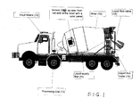
FIG. 1 is an environmental elevation view of a mixer employing a sensor of the instant invention for sensing aggregate concrete mixture; -
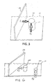
FIG. 2 is a diagrammatic view of the sensor for sensing concrete mixture within a rotating mixer ofFIG. 1 ; -
FIG. 3 is a diagrammatic view of forces acting onto the sensor ofFIG. 2 ; -
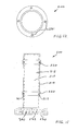
FIG. 4 is a perspective view of one embodiment of the sensor employed inFIG. 2 ; -
FIG. 5 is a block diagram of a control circuit employed with the sensor ofFIG. 4 ; -
FIG. 6 is illustrates an alternative form of the sensor ofFIG. 4 ; -
FIG. 7 is an elevation view of another form of the sensor ofFIG. 4 , adapted with a protective sleeve; -
FIG. 8 is a planar end view of the apparatus ofFIG. 7 ; -
FIG. 9 is a graph of sensor output with the protecting sleeve ofFIGS. 7-8 ; -
FIG. 10 is a graph of sensor output without the protecting sleeve ofFIGS. 7-8 ; -
FIG. 11 is an elevation view of another embodiment of a sensor for sensing concrete mixture within a rotating mixer ofFIG. 1 ; -
FIG. 12 is a planar end view of the apparatus ofFIG. 11 ; -
FIG. 13 is an elevation view of an alternative form of the sensor ofFIG. 11 ; -
FIG. 14 is a planar end view of the apparatus ofFIG. 13 ; -
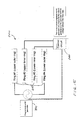
FIG. 15 is a block diagram showing connection of the sensor ofFIGS 13-14 to a control circuit; -
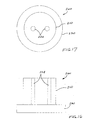
FIG. 16 is an elevation view of another alternative form of the sensor ofFIG. 11 ; -
FIG. 17 is a planar end view of the sensor ofFIG. 16 ; -
FIG. 18 is a diagrammatic elevation view of one form of a further embodiment of a sensor for sensing concrete mixture within a rotating mixer ofFIG. 1 ; and -
FIG. 19 is a diagrammatic planar view of another form of the further embodiment of a sensor for sensing concrete mixture within a rotating mixer ofFIG. 1 . - Prior to proceeding to the more detailed description of the present invention it should be noted that, for the sake of clarity and understanding, identical components which have identical functions have been identified with identical reference numerals throughout the several views illustrated in the drawing figures.
- Instant invention, in accordance with one embodiment, provides an improved sensor, generally designated as 100, for a
concrete mixer 10. Thesensor 100 comprises asensor body 110 and sensing elements mounted on a surface of or within thesensor body 110 and connectable to acontrol circuit 140. - Reference is now made, more particularly, to
FIGS. 1-6 , wherein aconcrete mixer 10, illustrated inFIG. 1 as a conventional rotating drum, has asensor 100 being attached to the wall of themixer 10 so that abody 110 of thesensor 100 extends, generally radially, into thehollow interior 11 of themixer 10. The presently preferred cross-sectional shape of thesensor body 110 is an annular ring. - Although conventionally it has been considered that the concrete mixture applies a force onto the
body 110 only in one direction being parallel to the rotational axis of theconcrete mixer 10, the inventor found that the mixingdrum 10 and, more particularly, the fins orblades 10a of the helix inside themixer 10 apply a force onto thesensor body 110 along a second axis being disposed at an angle to the rotational axis of themixer 10, as is best shown inFIG. 3 . - Accordingly, as is best shown in
FIG. 4 , thebody 110 is hollow, and the sensing elements includes at least two and preferably fourstrain gauges 120 mounted on aninterior round surface 112 of thehollow sensor body 110. Two of the fourstrain gauges 120, referenced for the sake of clarity with numeral 120a, are mounted, mediate ends of thehollow sensor body 110, along afirst axis 122 being parallel to an axis of rotation of theconcrete mixer 10 and the remaining twostrain gauges 120, referenced for the sake of clarity with numeral 120b, are mounted along asecond axis 124 being disposed at an angle to thefirst axis 122 when thesensor 100 is attached to the wall of theconcrete mixer 10. Thesecond axis 124 is defined by a rotation of the helix fin orblade 10a within themixer 10. Preferably,strain gauges sensor body 110 may be attached to the wall of themixer 10 by any conventional means and, preferably, thesensor 100 further comprises a base 130 attached, either permanently or removably, to one end of thehollow sensor body 110. The base 130 may be adapted with mountingapertures 131, so as to conventionally fasten thesensor 100 to the wall of themixer 10, either directly or through intermediate member(s). It is to be understood, that use of thestrain gauges sensor body 110 and thebase 130 and, thus such connection is preferably a rigid connection, for example such as by welding, threaded arrangement (not shown), friction fit or by a unitary one-piece construction of thesensor body 110 andbase 130, for example by a casting or a molding process. - Preferably, the
base 130 has a hollow interior 132, best shown inFIG 7 , wherein thecontrol circuit 140 is disposed within such hollow interior 132 of thebase 130 and includes a controller, preferably such as amicroprocessor 142, wherein the fourstrain gauges processor 142 in a Wheatstone bridge arrangement. Thecontrol circuit 140 further includes conventional A/D converter(s) 144 and signal amplifier(s) 146, as is bet shown inFIG. 5 . - In operation, measurement of the resistance of the
strain gauges sensor 100 by the movement of the concrete mixture in the direction of thestrain gauges 120a and in the direction of thestrain gauges 120b. - Preferably, the
strain gauges base 130 and to the inner surface of therotating drum 10 to take advantage of a condition wherein thesensor 100 rotates with the mixingdrum 10 and wherein the concrete mixture is pushed to the bottom of the concrete mixer (mixing drum 10). Thus, positioning thestrain gauges base 130 improves sampling of the concrete mixture by comparing results collected from each revolution of the mixingdrum 10. - Furthermore, the
strain gauges inner surface 112 of thehollow sensor body 110 and do not require any connection with the base 130 besides the electrical connections. - By way of one example only, the total force applied onto the
sensor 100 is calculated as the vector sum of both forces: - F - The total force applied onto the
sensor body 100 of thesensor 100. - Fp - The force applied on along
first axis 122 as measured bystrain gauges 120a. - Fv - The force applied along the
second axis 124 as measured bystrain gauges 120b.
- The slump of the concrete mixture is directly related to the force F and can be calculated from the measured force F by several ways, including a conversion table and a mathematical equation based on the Bingham model of non-Newtonian fluids.
- Rheological characteristics, such as viscosity and yield stress, can be also calculated by using the Bingham model. Additionally, calculating the variance between subsequent revolutions provides a mixing quality of the concrete mixture, wherein the lower the variance is, the better the concrete mixture is mixed.
- Now in a particular reference to
FIG. 6 , the instant invention also contemplates thatstrain gauges separate sensors 100. More specifically, the instant invention provides twosensors 100, each containing one and preferably twostrain gauges 120, wherein these twosensors 100 are oriented, at installation, such that the strain gauge(s) 120 is(are) disposed along thefirst axis 122 and the strain gauge (s) 120 is (are) disposed along thesecond axis 124. - The
sensor 100, and more particularly, thecontrol circuit 140, is operatively connected to acomputer processing unit 12 via wired or wireless connection. In operation, a particulate matter as an ingredient of concrete is added to themixer 10. Themixer 10 rotates and, as is conventional, thesensor body 110 and thesensing elements - Now in a further reference to
FIG. 1 , thecomputer processing unit 12 is operably connected to an input means 13, preferably one of a touch screen, voice recognition, keyboard and alphanumeric keypad (not shown). The input means 13 permits the user to enter one or more of the requested slump, mix and customer information. The instant invention contemplates that thecomputer processing unit 12 may integrate therewithin the above describedcontrol 140. - The desired slump, mix and the customer information is entered by the user. The
computer processing unit 12 determines the quantity of liquid to be added to themixer 10 to obtain the required slump based on the measured slump and water/cement ratio, the system will assure that the water/cement ratio will not be out of the required range. - The
concrete mixer 10 also has a conventionalliquid supply line 14 that is attached to and in fluid communication with theconcrete mixer 10 and has aliquid flow meter 15 and avalve 16 controlling the flow of liquid through the liquid supply line. Theliquid flow meter 15 andvalve 16 are operably connected to thecomputer processing unit 12. Theliquid flow meter 15 is preferably disposed within theliquid supply line 14 between thevalve 16 and theconcrete mixer 10. - It has been found by the inventor that there is a direct relationship between the angles that the
sensor 100 is submerged and emerged and the slump. Therefore, the slump can be determined through the analysis of the strain measurement in both first and second axis, 122 and 124 respectively, from the sensor(s) 100. - It has been found by the inventor that there is a direct relationship between the electrical resistance of the concrete mixture, as measured between two sensing parts of the sensor (or one electrode and the mixing drum itself) for various frequencies and the concrete water/cement ratio. Therefore, the water/cement ratio can be determined through the analysis of the resistance data as collected from the data from the
sensor 100. - It has been found by the inventor that there is a direct relationship between the electrical resistance of the concrete as measured between two sensing parts of the sensor 100 (or one electrode and the mixing drum itself) for various frequencies and the concrete permeability. Therefore, the permeability can be determined through the analysis of the resistance data as collected from the data from the
sensor 100. - The
computer processing unit 12 also analyzes the data from thesensor 100 to determine the amount of concrete mixture within themixer 10 by measuring the angle difference between the angle at the point thatsensor 100 was submerged and the angle in which it was emerged asmixer 10 rotates and thesensor 100 moves into the cement mixture and emerges from the cement mixture. The total number of degrees thatsensor 100 was submerged inside the concrete mixture indicates the level of the concrete mixture within themixer 10. As the concrete mixture is poured out, the concrete mixture level decreases within themixer 10. The data from thesensors 100 is used to record a change in the level of the concrete mixture and time that the level changes. The change in the quantity is the amount of the concrete mixture poured and the start and end time of the pour is recorded. - The knowledge of the remaining amount and slump of concrete in the mixture allows an adjustment in the quantities of solids and liquid to refill the
mixer 10 by the user. The knowledge of the amount poured permits accurate billing to the customer. The start and finish time allow the user to deter unauthorized pours by the mixer operator. - The knowledge of the remaining amount and permeability of the concrete solids in the mixture allows an adjustment in the quantities required to refill the
mixer 10 by the user. - Further, the data is stored in a data storage unit 17 operably connected to the
computer processing unit 12 to allow the use of the data as received or for the later retrieval of data. - Further, a pressure sensor (not shown) installed on the hydraulic system of the truck and connected to the system will provide data on the hydraulic system's "health", since there is a correlation between the hydraulic pressure, the slump and the quantity; any change in the hydraulic pressure for the same conditions will indicate that something is wrong with the hydraulic system.
- A display means 18 preferably a computer monitor is operably connected to a
computer processing unit 12. Also, an output means 19, preferably one of a printer, is operably connected to the computer processing unit. - Additionally, the presently preferred embodiment of the system includes a
moisture sensor 20 andtemperature sensor 21 that are operably connected to thecomputer processing unit 12. This additional sensors allow the user to further control the concrete mixture. - In the presently preferred embodiment, the system has a global positioning satellite receiver 30 with a digital output and a transmitter 40. The transmitter 40 is operatively connected to the
flow meter 15 andsensor 100 to transmit the location, stress or pressure data and flow of liquid to a remote location. The input means 13, output means 19,computer processing unit 12, data storage unit 17, display means 18 and output means may separately or in combination be situated at a remote location from themixer 10. - The
moisture sensor 20 andtemperature sensor 21, alone or in combination with each other, are operatively connected to a sensor display 22 that is at the pour location. - The input means 13 can be used by the user to override the
computer processing unit 12 and saidsensors 100 to manually control the process. - The invention also contemplates use of the data measured from the
sensor 100 and displayed on display 22 to control thevalve 16 manually. - The method of controlling the slump, includes the step of entering the slump mix characteristics, including the maximum water to cement ratio, the requested slump and the mixer characteristics. The force on a sensor within a
mixer 10 is calculated in terms of pressure or stress. The sensor output is monitored and the amount if any of additional liquid to be added to the mix is calculated. Approximately 85% to 95% of the amount of liquid is added to the mix. The mixer can then leave the plant and any additional liquid can be added at the site of the pour. The stress sensors are monitored and if the force is generally the calculated value the method in complete. - The method also contemplates use of an optional moisture sensor so as to monitor the moisture monitor and to use this data in calculating any additional liquid.
- Also, there is a method to maintain the consistency of the mixture. Rather than count mixer rotations, the present invention includes a method to maintain the consistency of the mixture by monitoring the electrical characteristics, the submerged and emerge angles and comparing them over several rotations. The mixture consistency is acceptable where the sensor data varies less than a predetermined range that varies by concrete application.
- Another method is provided to determine the quantity of concrete mixture within the mixing drum comprising: monitoring if a sensor is submerged into the concrete within a mixing drum; rotating such mixing drum; recording the time difference between the point where the sensor is at the top and the time it is submerged within such concrete; recording the total revolution time, recording the time difference between that such sensor submerged and emerges from such concrete mixture; and calculating the volume of concrete within such mixing drum analyzing the measured periods.
- Yet another method is provided to determine if the concrete mix within a mixing drum is consistent comprising: monitoring the rheological characteristics of the concrete by the sensor in the concrete per each revolution and calculating the variance between following revolutions, the lower the variance is, the better the concrete is mixed.
- In order to improve the performance of the sensors/
probes 100 and to increase their service period, a protection sleeve, generally designated as 150, is mounted onto anexterior surface 114 of thesensor body 110, as best shown inFIGS. 7-8 . Theprotection sleeve 150 is preferably comprised of two layers, asoft material layer 152 that surrounds theexterior surface 114 of thesensor body 110 and is being manufactured from a first material, and asecond layer 160 which surrounds an exterior surface of thefirst layer 152 and which is manufactured from a second material having a hardness thereof being greater than a hardness of the first material. The first material may be of an elastomeric type, such as rubber or the equivalent, to provide a protective layer to thesensor body 110 and dampen, cushion or absorb the shock onto thebody 110 from high abrasion created by the aggregates, corrosive materials inside the concrete mixture and alkaline water and at least substantially reduce if not completely eliminate noise factor of the measurement. Such first material layer is between about 1/8 inch and about 1 inch, preferably being about ½ inch in thickness. - The
layers sensor body 110 or thesleeve 150 may be provided as a unitary, one-piece construction. In either form, it is presently preferred to size theinterior surface 154 and select the durometer or hardness of the of thefirst layer 152 so as to allow ease of sliding the first layer of theexterior surface 114 of thesensor body 110. Then, theprotective sleeve 150 can be easily replaced in the field so as to extend the service life of thesensor 100. - The hardness of the second material is sufficient to resist wear of the
body 110 from contact with the aggregate concrete mixture. More specifically, the hardness of the second material is sufficient to resist a movement of the aggregate concrete mixture and allow thesensor 100 to measure rheological characteristics of the aggregate concrete mixture in a manner that substantially reduces if not completely eliminates signal/measurement noise. By way of one example only, the second material may be a metal or equivalent. Thesecond material layer 160, which is the external layer, covers the sensing part of thesensor body 110 and is made out of a hard wear-resistant material that will resist the movement of the concrete and allow thesensor 100 to measure the rheological characteristics of the aggregate concrete mixture, if the material exposed for contact to the aggregate concrete mixture will be a soft material then thesensor 100 will measure the friction between the sensor and the concrete mixture and not the rheological characteristics. In other words, although being operable under some conditions, particularly, where the accuracy is not of a concern, thesensor 100 will not accurately measure the rheological characteristics of the aggregate concrete mixture when thesoft layer 152 is not covered by thehard layer 160 due to abrasion ofsuch layer 152 by the aggregate concrete mixture. - The inventor has discovered that the combination of a
first layer 152 andsecond layer 160 materially improves the measurement of the rheological characteristics of the concrete mixture. It has been found that the combination acts as a filter, reducing the effect of the turbulence caused by the movement of thesensor 100 through the concrete mixture. The two layered structure gives the following advantages: thesensor 100 is less prone to damages caused by the environment; the service period of thesensor 100 is increased because thesleeve 150 and/or the sensor body 110 (being removably attached to the base 130) that comes in contact with the concrete mixture can be replaced at a much lower cost than thewhole sensor 100; and the readings fromsuch sensor 100 are more reliable and easier to process due to an improved noise to signal ratio. The performance improvements are demonstrated inFIG. 9 , wherein thesensor 100 is used with thesleeve 150 vs.FIG. 10 , wherein thesensor 100 is employed without asleeve 150. In both figures, vertical axis defines force and horizontal axis defines times.FIG. 9 clearly shows an improved ratio between the signal and the noise. - Although, the
sleeve 150 has been described for use with the above describedsensor 100, thesleeve 150 can be used to improve any existing sensor/probe design, for example, of the type as described in theU.S. Pat. Pub. Number 2012/0204625 to Beaupre et al. , whose teachings are incorporated herein by reference thereto. - The instant invention contemplates that
strain gauges exterior surface 114 of thesensor body 110, particularly, when thesensor 110 is adapted with the above describedsleeve 150. In either form, thestrain gauges sensor body 110 andprotective sleeve 150. -
FIGS. 11-17 illustrate additional forms of another embodiments of the invention wherein the sensor, generally designated as 200, comprises at least a pair of sensing elements, such as electrically conductive members orelectrodes 220, either positioned on anexterior surface 212 of thesensor body 210 in a spaced apart relationship with each other, as best shown inFIGS. 11-14 or imbedded into thesensor body 210, as best shown by sensingelements 224 inFIGS. 16-17 . - The
sensor 200 in these forms measures the electrical resistance and impedance between oneelectrode 220 and the mixer itself (in case themixer 10 is made of metal) or between spacedelectrodes 220 that come in contact with the concrete mixture. - In the form of
FIGS. 11-14 , thesensor body 210 is preferably hollow and is manufactured from an electrically non-conductive material. The sensing elements include two ring-shaped electrically conductive members orelectrodes 220 mounted in a spaced apart relationship with each other on anexterior surface 212 of thehollow sensor body 210 and wherein thesensor 200 further comprises a base 230 attached to one end of thehollow sensor body 210 and acontrol circuit 240 disposed within ahollow interior 232 of thebase 230, thecontrol circuit 240 being at least configured to generate and apply voltage to the two ring-shaped electricallyconductive members 220 and measure a current between the two ring-shaped electricallyconductive members 220, the current being indicative of at least one of a resistance and impedance of a concrete mixture contained within themixer 10. It would be understood that the electricallyconductive members 220 can be provided in other shapes to match the peripheral shape of thesensor body 210. Thesensor body 210 may be further provided withapertures 211 so as to physically connect electrical wires (not shown) from thecontrol circuit 240 to the electricallyconductive members 220, wherein the electricallyconductive members 220 are ultimately coupled to a processor within thecontrol circuit 240. - The
control circuit 240, at least contains the above describedprocessor 142 and, in addition to programming the AC generator 250 to specific frequency and voltage, is configured to measure the current consumed by the AC generator 250 (being a frequency generator or a sine wave), measure the voltage between theinner rings 220, calculate the resistance of the concrete based on the formula R=V/I, determine if thesensor body 210 is submerged in the concrete mixture or out of the concrete mixture, determine the location of thesensor 200 by using measurements from anoptional accelerometer 170, and determine the entry and departure angles of thesensor 200. Thecontrol circuit 240 is further being either configured to calculate the slump and the volume of the concrete mixture based on the angles values and the water to cement ratio based on the resistance or transmit all relevant data to thecomputer processing unit 12 that will calculate the slump and the volume of the concrete mixture based on the angles values and the water to cement ratio based on the resistance and make any adjustments to the concrete mixture within themixer 10 as/if required. It must be noted that thecomputer processing unit 12 may be configured to incorporate thecontrol circuit 240 or the previously describedcontrol circuit 140. - It is presently preferred that the
sensor body 210 is hollow and is manufactured from an electrically non-conductive material and wherein the sensing elements include four ring-shaped electricallyconductive members 200 mounted in a spaced apart relationship with each other on theexterior surface 212 of thehollow body 210. Thesensor 200, in this form, also includes the above describedbase 230, preferably with the mountingapertures 231, and being preferably connected to thesensor body 210 by the above described rigid connection. Further, thecontrol circuit 240 is preferably disposed within thehollow interior 232 of thebase 230 and further includes the programmable AC generator 250 disposed within thehollow interior 232 of thebase 230. The programmable AC generator 250 being operatively coupled to thecontrol circuit 240 and to outer electricallyconductive members 220. Further, two inner electricallyconductive members 220 are operatively coupled to thecontrol circuit 240, wherein thecontrol circuit 240 is configured to program the programmable AC generator 250, measure a current generated by the programmable AC generator 250 and measure a voltage between the innerconductive members 220. - Although the voltage can be measured between the outer electrically
conductive members 220, it has been found that some of the current will drift and the measured resistance is the combined resistance of the concrete mixture and additional noise. When the voltage is measured on the innerconductive members 220 and the current is known from feeding circuit, then it has been found that the voltage measured is only on the resistance of the concrete mixture. - In either embodiment, the electrical resistance is measured both in DC and in AC (in varying frequencies) the result is a spectrum of electrical resistances. The
sensor 200 also measures the phase shift of the AC signal to measure the impedance. - The measurement is done while the
mixer 10 is rotating and thesensor 200 travels along the circumference of themixer 10 and measures the resistance/impedance. Once thesensor 200 is submerged into the concrete mixture, there is a huge reduction the electrical resistance as measured by the electricallyconductive members 220. So thesensor 200 can distinguish between measurements done inside the concrete mixture and those outside the concrete mixture. - By using an
accelerometer 170, the system can identify where thesensor 200 was submerged into the concrete mixture and where it went out of the concrete mixture. The analysis of both locations will give two angles as measured from the highest point of the sensor, entry angle (α1) and leave angle (α2) the difference between the two angles has direct correlation to the slump of the concrete mixture, and the average between the two angles has a direct correlation to the level of the concrete mixture in themixer 10 and from there to the volume of the concrete mixture. - The presently preferred method of determining volume and slump is based on using
sensor 200 to measure electrical resistance and is further based on finding the locations of thesensor 200 entering and leaving the concrete by measuring the total revolution time (T1), the total submerged time (T2), the time elapsed from the point thesensor 200 was at the highest point and the time it submerged into the concrete (T3) and the time elapsed since it went out of the concrete until it came back to the highest point (T4). Identifying the highest point can be done by using a simple weight attached to a load cell either vertically or horizontally, there are two points where the load cell will have the same value, at the top and at the bottom (this value can be obtained during a simple calibration process of mounting the sensor vertically and measuring the force applied on the load cell by the weight), the electrical resistance will determine if thesensor 200 is at the lowest point (submerged) or at the highest point (out of the concrete), if the sensor can't identify that it means the mixer is empty (the identification of this status will be used for identifying if the pouring process is over. Accordingly, the volume and slump can be calculated as follows:


wherein: - f=function
- g=function
- W=Water
- C=Cement
- w=function
- R=resistance
- Functions f, g, and w can be obtained from translations tables developed, for example, by historical measurements.
- In case we do not use an accelerometer and just use simple time calculations, the angles can be calculated in the following manner:


- The invention also contemplates use of predefined conversion tables, obtained during a calibration process, instead of using the above functions.
- In yet another embodiment of
FIG. 18 , the invention provides a sensor, generally designated as 300, that includes asensor body 310 having ahollow interior 312. Thesensor 300 further includes a pair of pressuretype load cells 320 mounted within thehollow interior 312 to measure forces in two directions, being generally perpendicular to each other. By way of one example only, thebody 310 is provided as a hollow body and thesensor 300 further includes a pair ofbraces hollow body 310 but oriented generally perpendicular to each other. - The
sensor 300 preferably includes a base 330 that is connected to one end of thebody 310 by way of aflexible connection 338 allowing movement of thebody 310 relative to thebase 330. Such flexible connection could be of the type, for example as disclosed inU.S. Pat. Pub. Number 2012/0204625 to Beaupre et al. - In an alternative form of
FIG. 19 , the pair of sensing elements may be provided asbeam load cells 370. Eachbeam load cell 370 will be mounted on thebase 330, however, one of the two beam load cells will be also connected to abrace 372, while the secondbeam load cells 370 will be free standing on thebase 330. Thebeam load cells 370 are also connected therebetween with a flexible connection that may be the above describedflexible connection 338. - It would be understood that the instant invention can be configured with use of two
sensors 300, each containing a single pressuretype load cell 20 or a singlebeam load cells 370, wherein thesensors 300 are so mounted that eachsensor 300 senses force in a distinct direction. - The reader is advised that the above described
sensor 300 may be employed with the above describedprotective sleeve 150. - Furthermore, the method of measuring volume and slump of the concrete mixture with sensor(s) 300 is generally identical to a method employing the above described sensor(s) 100.
- In the conventional mixing process, with either one of the above described embodiment, the
mixer 10 is required to idle and count the mixer revolutions to attempt to achieve a consistent mixture. The present invention allows the user to charge themixer 10 and leave the yard, monitoring of the slump and the electrical characteristics over several revolutions. The deviation from the average will indicate if the material is well mixed, the lower the deviation is the better the mix is mixed. Similarly comparison of this data to data obtained from "standard" or baseline batch configuration will indicate if this batch is similar to the "standard" batch. - Further, the change in the mix volume and the start and stop time of the change in volume are recorded. Thus, the user of the present invention will know the amount of concrete mixture poured, as well as the time of the pour, thus preventing a financial loss through unauthorized pours. The user may also receive an alert as to the need to recharge the
mixer 10. - The embodiments disclosed hereinabove may be summarized as follows.
- Embodiment 1:
- A sensor for a concrete mixer, said sensor comprising:
- (a) a body; and
- (b) sensing elements mounted on an exterior surface of or within an interior of said body and connectable to a control circuit.
- A sensor for a concrete mixer, said sensor comprising:
- Embodiment 2:
- The sensor of
Embodiment 1, wherein said sensing elements are so mounted that said sensor is configured, during a movement of said sensor through a concrete mixture, to measure a first force along a first axis being parallel to an axis of rotation of said concrete mixer and measure a second force along a second axis being disposed at an angle to said first axis, said second axis defined by a movement of a mixing helix within said concrete mixer.
- The sensor of
- Embodiment 3:
- The sensor of
Embodiment 1, wherein said body is hollow, wherein said sensing elements includes four strain gauges mounted on an interior surface of said hollow body and wherein two of said four strain gauges are mounted, mediate ends of said hollow body, along a first axis being parallel to an axis of rotation of said concrete mixer and remaining two strain gauges are mounted along a second axis being disposed at an angle to said first axis when said sensor is attached to a wall of the concrete mixer, said second axis defined by a movement of a mixing helix within said concrete mixer.
- The sensor of
- Embodiment 4:
- The sensor of
Embodiment 3, wherein said sensor further comprises a base attached to one end of said hollow body and said control circuit being disposed within a hollow interior of said base, said control circuit including a processor and wherein said four strain gauges are connected with wires to said processor in a Wheatstone bridge arrangement.
- The sensor of
- Embodiment 5:
- The sensor of
Embodiment 1, wherein said body is manufactured from an electrically non-conductive material and wherein said sensing elements include four electrically conductive members mounted in a spaced apart relationship with each other along a length of said body on an exterior surface thereof.
- The sensor of
- Embodiment 6:
- The sensor of
Embodiment 5, further comprising a base and a rigid connection between said base and one end of said body.
- The sensor of
- Embodiment 7:
- The sensor of Embodiment 6, further comprising:
- (a) a hollow interior within said base;
- (b) a control circuit disposed within said hollow interior of said base;
- (c) a programmable AC generator disposed within said hollow interior of said base, said programmable AC generator operatively coupled to control circuit and to outer electrically conductive members;
- (d) wherein inner electrically conductive members are operatively coupled to said control circuit; and
- (e) wherein said control circuit is at least configured to program said programmable AC generator, measure a current generated by said programmable AC generator and measure a voltage between said inner electrically conductive members.
- The sensor of Embodiment 6, further comprising:
- Embodiment 8:
- The sensor of
Embodiment 1, wherein said body is manufactured from an electrically non-conductive material, wherein said sensing elements include two electrically conductive members mounted in a spaced apart relationship with each other on an exterior surface of said body and wherein said sensor further comprises a base attached to one end of said body and a control circuit disposed within a hollow interior of said base, said control circuit is configured to generate and apply voltage to said two electrically conductive members and measure a current between said two electrically conductive members, said current being indicative of at least one of a resistance and impedance of a concrete mixture contained within the concrete mixer.
- The sensor of
- Embodiment 9:
- The sensor of
Embodiment 1, further comprising:- (a) a base attached to one end of said body;
- (b) a control circuit disposed within a hollow interior of said base;
- (c) said sensing elements defining two elongated electrically conductive members integrated in a spaced apart relationship within said body and electrically connected to said control circuit;
- (d) wherein said body is manufactured from an electrically non-conductive material; and
- (e) wherein said control circuit is configured to generate and apply voltage to said two elongated electrically conductive members and measure a current between said two elongated electrically conductive members, said current being indicative of at least one of a resistance and impedance of a concrete mixture contained within the concrete mixer.
- The sensor of
- Embodiment 10:
- The sensor of
Embodiment 1, wherein said body is hollow, wherein said sensor further includes a base, a flexible connection between said base and one end of said hollow body and two brace members mounted, generally perpendicular to each other, within said hollow body wherein each end of each brace member is attached to an interior surface of said hollow body; wherein said sensing elements include a pair of pressure load cells, and wherein one of said pair of pressure load cells is mounted on one of said two brace members and another one of said pair of pressure load cells is mounted on another one of said two brace members; and wherein said; whereby said sensor is configured to measure a first force along a first axis being parallel to an axis of rotation of said concrete mixer and further measure a second force along a second axis being disposed at an angle to said first axis when said sensor is attached to a wall of said concrete mixer.
- The sensor of
- Embodiment 11:
- The sensor of
Embodiment 1, wherein said body is hollow, wherein said sensor further includes a base, a flexible connection between said base and one end of said hollow body and a brace member having each end thereof attached to an interior surface of said hollow body; wherein said sensing elements include a pair of beam load cells connected therebetween and further connected to said base and extending into said hollow body, and wherein one of said pair of beam load cell is further connected to said brace member; whereby said sensor is configured to measure a first force along a first axis being parallel to an axis of rotation of said concrete mixer and further measure a second force along a second axis being disposed at an angle to said first axis when said sensor is attached to a wall of said concrete mixer.
- The sensor of
- Embodiment 12:
- A sensor for a concrete mixer, comprising:
- (a) a body;
- (b) one or more sensing elements mounted on an exterior surface or within an interior of said body and connectable to a control circuit; and
- (c) a sleeve, including:
- i. a first layer surrounding said exterior surface of said body and manufactured from a first material,
- ii. a second layer surrounding an exterior surface of said first layer and manufactured from a second material, and
- iii. wherein said second material has a hardness thereof being greater than a hardness of said first material.
- A sensor for a concrete mixer, comprising:
- Embodiment 13:
- The sensor of
Embodiment 12, wherein said hardness of said second material is sufficient to resist a wear of said second material layer from a contact with a concrete mixture.
- The sensor of
- Embodiment 14:
- The sensor of
Embodiment 12, wherein said hardness of said second material is sufficient to cushion shocks during a movement of said sensor through a concrete mixture and to reduce a noise factor therefrom while allowing said sensor to measure rheological characteristics of the concrete mixture.
- The sensor of
- Embodiment 15:
- A system for measuring rheological properties in a concrete mixer, comprising:
- (a) one or more rheological sensors, each including a body thereof disposed within a hollow interior of said concrete mixer and one or more sensing elements mounted on an exterior surface of or within an interior of said body;
- (b) a control circuit connected to said sensing elements; and
- (c) whereby said rheological system is configured to measure a first force along a first axis being parallel to an axis of rotation of said concrete mixer and further measure a second force along a second axis being disposed at an angle to said first axis when said sensor is attached to a wall of said concrete mixer, said second axis defined by a movement of a mixing helix within said concrete mixer.
- A system for measuring rheological properties in a concrete mixer, comprising:
- Embodiment 16:
- A system for measuring rheological properties in a concrete mixer, comprising:
- (a) one or more sensors, each including an electrically non-conductive sensor body thereof disposed within a hollow interior of said concrete mixer and one or more electrically conductive members mounted on an exterior surface of said electrically non-conductive sensor body;
- (b) a control circuit connected to said electrically conductive members and operable to at least connect voltage to said electrically conductive members; and
- (c) whereby said system is configured to determine at least one of a volume and a slump based on a measurement of an electrical resistance on said electrically conductive members during movement of said one or more sensors through an aggregate concrete mixture in said concrete mixer and further based on a measurement of entry and exit angles of said one or more sensors into and from the aggregate concrete mixture.
- A system for measuring rheological properties in a concrete mixer, comprising:
- Embodiment 17:
- A method for measuring rheological properties of an aggregate concrete mixture in a concrete mixer, said method comprising the steps of:
- (a) providing one or more sensors, each including an electrically non-conductive sensor body and one or more electrically conductive members mounted on an exterior surface of said electrically non-conductive sensor body;
- (b) mounting said one or more sensors so that said electrically non-conductive sensor body thereof is disposed within a hollow interior of said concrete mixer and within said aggregate concrete mixture during a rotation of said concrete mixer;
- (c) connecting a control circuit to said electrically conductive members;
- (d) applying, with said control circuit, a voltage to said electrically conductive members;
- (e) moving said one or more sensors through said aggregate concrete mixture in said concrete mixer;
- (f) measuring, with said control circuit, an electrical resistance value on said one or more electrically conductive members;
- (g) measuring, with said control circuit, entry and exit angles of said one or more sensors into and from said aggregate concrete mixture; and
- (h) determining, with said control circuit, at least one of a volume and a slump of said aggregate concrete mixture based on a measurement of said electrical resistance in step (f) and a measurement of said entry and exit angles in step (g).
- A method for measuring rheological properties of an aggregate concrete mixture in a concrete mixer, said method comprising the steps of:
- While a presently preferred and various alternative embodiments of the present invention have been described in sufficient detail above to enable a person skilled in the relevant art to make and use the same it should be obvious that various other adaptations and modifications can be envisioned by those persons skilled in such art without departing from either the spirit of the invention or the scope of the appended claims.
- The invention has industrial use in the concrete production industry.
Claims (15)
- A sensor for a concrete mixer, comprising:(a) a body;(b) one or more sensing elements mounted on an exterior surface or within an interior of said body and connectable to a control circuit; and(c) a sleeve, including:i. a first layer surrounding said exterior surface of said body and manufactured from a first material,ii. a second layer surrounding an exterior surface of said first layer and manufactured from a second material, andiii. wherein said second material has a hardness thereof being greater than a hardness of said first material.
- The sensor of claim 1, wherein said hardness of said second material is sufficient to resist a wear of said second material layer from a contact with a concrete mixture.
- The sensor of claim 1, wherein said hardness of said second material is sufficient to cushion shocks during a movement of said sensor through a concrete mixture and to reduce a noise factor therefrom while allowing said sensor to measure rheological characteristics of the concrete mixture.
- The sensor of claim 1, wherein said sensing elements are so mounted that said sensor is configured, during a movement of said sensor through a concrete mixture, to measure a first force along a first axis being parallel to an axis of rotation of said concrete mixer and measure a second force along a second axis being disposed at an angle to said first axis, said second axis defined by a movement of a mixing helix within said concrete mixer.
- The sensor of claim 1, wherein said body is hollow, wherein said sensing elements includes four strain gauges mounted on an interior surface of said hollow body and wherein two of said four strain gauges are mounted, mediate ends of said hollow body, along a first axis being parallel to an axis of rotation of said concrete mixer and remaining two strain gauges are mounted along a second axis being disposed at an angle to said first axis when said sensor is attached to a wall of the concrete mixer, said second axis defined by a movement of a mixing helix within said concrete mixer.
- The sensor of claim 5, wherein said sensor further comprises a base attached to one end of said hollow body and said control circuit being disposed within a hollow interior of said base, said control circuit including a processor and wherein said four strain gauges are connected with wires to said processor in a Wheatstone bridge arrangement.
- The sensor of claim 1, wherein said body is manufactured from an electrically non-conductive material and wherein said sensing elements include four electrically conductive members mounted in a spaced apart relationship with each other along a length of said body on an exterior surface thereof.
- The sensor of claim 7, further comprising a base and a rigid connection between said base and one end of said body.
- The sensor of claim 8, further comprising:(a) a hollow interior within said base;(b) a control circuit disposed within said hollow interior of said base;(c) a programmable AC generator disposed within said hollow interior of said base, said programmable AC generator operatively coupled to control circuit and to outer electrically conductive members;(d) wherein inner electrically conductive members are operatively coupled to said control circuit; and(e) wherein said control circuit is at least configured to program said programmable AC generator, measure a current generated by said programmable AC generator and measure a voltage between said inner electrically conductive members.
- The sensor of claim 1, wherein said body is manufactured from an electrically non-conductive material, wherein said sensing elements include two electrically conductive members mounted in a spaced apart relationship with each other on an exterior surface of said body and wherein said sensor further comprises a base attached to one end of said body and a control circuit disposed within a hollow interior of said base, said control circuit is configured to generate and apply voltage to said two electrically conductive members and measure a current between said two electrically conductive members, said current being indicative of at least one of a resistance and impedance of a concrete mixture contained within the concrete mixer.
- The sensor of claim 1, further comprising:(a) a base attached to one end of said body;(b) a control circuit disposed within a hollow interior of said base;(c) said sensing elements defining two elongated electrically conductive members integrated in a spaced apart relationship within said body and electrically connected to said control circuit;(d) wherein said body is manufactured from an electrically non-conductive material; and(e) wherein said control circuit is configured to generate and apply voltage to said two elongated electrically conductive members and measure a current between said two elongated electrically conductive members, said current being indicative of at least one of a resistance and impedance of a concrete mixture contained within the concrete mixer.
- The sensor of claim 1, wherein said body is hollow, wherein said sensor further includes a base, a flexible connection between said base and one end of said hollow body and two brace members mounted, generally perpendicular to each other, within said hollow body wherein each end of each brace member is attached to an interior surface of said hollow body; wherein said sensing elements include a pair of pressure load cells, and wherein one of said pair of pressure load cells is mounted on one of said two brace members and another one of said pair of pressure load cells is mounted on another one of said two brace members; and wherein said; whereby said sensor is configured to measure a first force along a first axis being parallel to an axis of rotation of said concrete mixer and further measure a second force along a second axis being disposed at an angle to said first axis when said sensor is attached to a wall of said concrete mixer.
- The sensor of any one of the preceding claims, wherein said first layer is manufactured of an elastomeric material.
- The sensor of any one of the preceding claims, wherein said second layer is manufactured of a metal material.
- A method comprising:measuring a concrete mixture using a sensor comprising:(a) a body;(b) one or more sensing elements mounted on an exterior surface or within an interior of said body and connectable to a control circuit; and(c) a sleeve, including:i. a first layer surrounding said exterior surface of said body and manufactured from a first material,ii. a second layer surrounding an exterior surface of said first layer and manufactured from a second material, andiii. wherein said second material has a hardness thereof being greater than a hardness of said first material.
Applications Claiming Priority (3)
| Application Number | Priority Date | Filing Date | Title |
|---|---|---|---|
| US201361751663P | 2013-01-11 | 2013-01-11 | |
| EP14737677.6A EP2943321B1 (en) | 2013-01-11 | 2014-01-10 | Concrete mixture measurement sensor and method |
| PCT/IB2014/000024 WO2014108798A2 (en) | 2013-01-11 | 2014-01-10 | Concrete mixture measurement sensor, system and method |
Related Parent Applications (2)
| Application Number | Title | Priority Date | Filing Date |
|---|---|---|---|
| EP14737677.6A Division EP2943321B1 (en) | 2013-01-11 | 2014-01-10 | Concrete mixture measurement sensor and method |
| EP14737677.6A Division-Into EP2943321B1 (en) | 2013-01-11 | 2014-01-10 | Concrete mixture measurement sensor and method |
Publications (2)
| Publication Number | Publication Date |
|---|---|
| EP2977163A1 true EP2977163A1 (en) | 2016-01-27 |
| EP2977163B1 EP2977163B1 (en) | 2019-03-13 |
Family
ID=51167468
Family Applications (2)
| Application Number | Title | Priority Date | Filing Date |
|---|---|---|---|
| EP14737677.6A Active EP2943321B1 (en) | 2013-01-11 | 2014-01-10 | Concrete mixture measurement sensor and method |
| EP15180076.0A Active EP2977163B1 (en) | 2013-01-11 | 2014-01-10 | Concrete mixture measurement sensor and method |
Family Applications Before (1)
| Application Number | Title | Priority Date | Filing Date |
|---|---|---|---|
| EP14737677.6A Active EP2943321B1 (en) | 2013-01-11 | 2014-01-10 | Concrete mixture measurement sensor and method |
Country Status (5)
| Country | Link |
|---|---|
| US (1) | US10041928B2 (en) |
| EP (2) | EP2943321B1 (en) |
| CA (1) | CA2896786C (en) |
| MX (1) | MX364983B (en) |
| WO (1) | WO2014108798A2 (en) |
Cited By (1)
| Publication number | Priority date | Publication date | Assignee | Title |
|---|---|---|---|---|
| US11897167B2 (en) | 2019-01-17 | 2024-02-13 | Oshkosh Corporation | Concrete sensor system |
Families Citing this family (30)
| Publication number | Priority date | Publication date | Assignee | Title |
|---|---|---|---|---|
| CA2725887C (en) * | 2008-05-28 | 2015-02-24 | Katzeff-Berman, Dully | Concrete slump measurement and control system |
| US9836801B2 (en) | 2012-01-23 | 2017-12-05 | Quipip, Llc | Systems, methods and apparatus for providing comparative statistical information in a graphical format for a plurality of markets using a closed-loop production management system |
| US9254583B2 (en) | 2012-01-23 | 2016-02-09 | Quipip, Llc | Systems, methods and apparatus for providing comparative statistical information for a plurality of production facilities in a closed-loop production management system |
| US10184928B2 (en) | 2014-01-29 | 2019-01-22 | Quipip, Llc | Measuring device, systems, and methods for obtaining data relating to condition and performance of concrete mixtures |
| BR112017001485A2 (en) * | 2014-07-24 | 2017-12-05 | Gcp Applied Tech Inc | self-cleaning concrete mix monitoring |
| US10215670B2 (en) | 2016-01-26 | 2019-02-26 | Quipip, Llc | Systems, apparatus and methods for obtaining measurements concerning the strength and performance of concrete mixtures |
| CA3012002C (en) | 2016-02-01 | 2023-09-12 | Quipip, Llc | Sensing device, sensing device system, and methods for measuring a characteristic of a concrete mixture and for predicting a performance characteristic of a concrete mixture |
| WO2018005460A1 (en) * | 2016-06-27 | 2018-01-04 | Quipip, Llc | Sensing device, and systems and methods for obtaining data relating to concrete mixtures and concrete structures |
| WO2018035124A1 (en) * | 2016-08-17 | 2018-02-22 | Quipip, Llc | Sensing device, and systems and methods for obtaining data relating to concrete mixtures and concrete structures |
| BR112019001381A2 (en) * | 2016-08-31 | 2019-04-30 | Command Alkon Incorporated | rheological probe |
| CA3047063C (en) * | 2016-12-22 | 2021-07-06 | Command Alkon Incorporated | Methods and systems for handling fresh concrete |
| US20200232966A1 (en) * | 2017-07-28 | 2020-07-23 | Command Alkon Incorporated | Methods and System for Measuring Density of Fresh Concrete |
| EP3664925B1 (en) * | 2017-08-11 | 2024-02-14 | GCP Applied Technologies Inc. | Grey water measurement |
| EP3673245A4 (en) * | 2017-08-22 | 2021-07-28 | Cidra Corporate Services LLC | Techniques for sensing the volume and/or viscosity of concrete in a rotating container |
| WO2019062280A1 (en) * | 2017-09-26 | 2019-04-04 | 中国恩菲工程技术有限公司 | System for testing rheological behavior of slurry |
| US11815505B2 (en) * | 2017-09-29 | 2023-11-14 | Quipip, Llc | Sensor device, and systems and methods for obtaining and providing information relating to concrete mixtures and construction projects |
| CA3076101A1 (en) * | 2017-10-03 | 2019-04-11 | Command Alkon Incorporated | Method and system for mixing concrete constituents in a drum |
| US10870219B2 (en) | 2017-10-11 | 2020-12-22 | Caterpillar Inc. | Monitoring system for three-dimensional printing |
| US11402312B2 (en) * | 2018-02-08 | 2022-08-02 | Command Alkon Incorporated | Methods and systems for handling fresh concrete based on hydraulic pressure and on rheological probe pressure |
| WO2019213342A1 (en) * | 2018-05-02 | 2019-11-07 | Command Alkon Incorporated | System having drum discharge outlet sensors and method of characterizing fresh concrete delivery using same |
| CA3094850A1 (en) * | 2018-05-02 | 2019-11-07 | Command Alkon Incorporated | Methods for determining fresh concrete discharge volume and discharge flow rate and system using same |
| CN109373189B (en) * | 2018-10-24 | 2024-04-30 | 中国建筑股份有限公司 | Device and method for measuring blocking position of concrete pump pipe |
| WO2020231728A1 (en) * | 2019-05-10 | 2020-11-19 | Gcp Applied Technologies Inc. | Instrument for direct measurement of air content in a liquid using a resonant electroacoustic transducer |
| EP4007902A4 (en) * | 2019-08-01 | 2023-08-02 | GCP Applied Technologies Inc. | Rotated concrete volume determination |
| US20210237311A1 (en) * | 2020-02-05 | 2021-08-05 | Oshkosh Corporation | Systems and methods for controlling discharge of a mixer drum |
| US11833713B2 (en) * | 2020-03-06 | 2023-12-05 | Oshkosh Corporation | Axle pressure setting systems and methods |
| CN111912746B (en) * | 2020-06-09 | 2022-08-02 | 广西大学 | Quantitative evaluation method for analyzing concrete workability based on bottom resistance |
| US11312039B1 (en) * | 2021-05-06 | 2022-04-26 | Command Alkon Incorporated | System and method for monitoring fresh concrete being handled in a concrete mixer using trained data processing engines |
| CN114324833B (en) * | 2021-12-06 | 2024-04-19 | 富强科技股份有限公司 | Concrete slump control process for long-time transportation |
| WO2023230314A1 (en) * | 2022-05-27 | 2023-11-30 | Command Alkon Incorporated | Methods of loading concrete ingredients into a drum of a concrete mixer truck and system therefore |
Citations (7)
| Publication number | Priority date | Publication date | Assignee | Title |
|---|---|---|---|---|
| US3147612A (en) * | 1962-09-14 | 1964-09-08 | Fischer & Porter Co | Consistency measuring apparatus |
| US3631712A (en) * | 1970-02-24 | 1972-01-04 | Julian J Mercier | Method and apparatus for determining slump in concrete |
| US5713663A (en) | 1995-05-15 | 1998-02-03 | Boral Resources (Vic) Pty Limited | Method and apparatus for mixing concrete in a concrete mixing device to a specified slump |
| EP0924040A1 (en) | 1997-12-17 | 1999-06-23 | Esi Elettrosistemi S.r.l. | A device for gauging the consistency of a mixture during mixing in a rotary recipient |
| US6484079B2 (en) | 2000-04-28 | 2002-11-19 | Rmc Industries Corporation | Methods and systems for remotely monitoring sensor data in delivery vehicles |
| EP1961538A2 (en) | 2005-11-28 | 2008-08-27 | Eugenio Bonilla Benegas | Automatic system for monitoring the mixing of conglomerates |
| US20120204625A1 (en) | 2009-10-07 | 2012-08-16 | I.B.B. Rheologie Inc. | Probe and Method for Obtaining Rheological Property Value |
Family Cites Families (13)
| Publication number | Priority date | Publication date | Assignee | Title |
|---|---|---|---|---|
| US3129928A (en) * | 1961-06-16 | 1964-04-21 | Butler Bin Company | Water feed control system for concrete mixers |
| US3753373A (en) * | 1965-10-22 | 1973-08-21 | Bissett Berman Corp | Transducer system |
| US3640121A (en) * | 1970-03-09 | 1972-02-08 | Julian J Mercier | Slump indicator |
| DE2952124A1 (en) * | 1979-12-22 | 1981-07-02 | Elba-Werk Maschinen-Gesellschaft Mbh & Co, 7505 Ettlingen | Batch of concrete preparation method |
| JPH06100524B2 (en) * | 1985-09-20 | 1994-12-12 | 藤沢薬品工業株式会社 | Granulation end point detection method |
| DE3732231A1 (en) * | 1987-09-24 | 1989-04-13 | Hudelmaier Ingrid | METHOD FOR DETERMINING THE CONSISTENCY OF CONCRETE AND RELATED CONCRETE MIXERS |
| FI120604B (en) | 2001-10-31 | 2009-12-15 | Consolis Technology Oy Ab | Method for improving the accuracy of humidity measurement based on electrical properties or electromagnetic wave motion |
| DK1664732T3 (en) * | 2003-09-24 | 2008-09-08 | Convi | A method of measuring a blend consistency as well as an apparatus for practicing the method |
| US8764272B2 (en) | 2008-04-07 | 2014-07-01 | W. R. Grace & Co., -Conn. | Method for monitoring thixotropy in concrete mixing drum |
| CA2725887C (en) * | 2008-05-28 | 2015-02-24 | Katzeff-Berman, Dully | Concrete slump measurement and control system |
| US8311678B2 (en) | 2010-06-23 | 2012-11-13 | Verifi Llc | Method for adjusting concrete rheology based upon nominal dose-response profile |
| US9429559B2 (en) * | 2014-01-29 | 2016-08-30 | Quipip, Llc | Systems, methods and apparatus for obtaining data relating to condition and performance of concrete mixtures |
| JP6269142B2 (en) | 2014-02-14 | 2018-01-31 | 東芝ライテック株式会社 | Control device, control method, program, and power control system |
-
2014
- 2014-01-10 MX MX2015008951A patent/MX364983B/en active IP Right Grant
- 2014-01-10 WO PCT/IB2014/000024 patent/WO2014108798A2/en active Application Filing
- 2014-01-10 EP EP14737677.6A patent/EP2943321B1/en active Active
- 2014-01-10 CA CA2896786A patent/CA2896786C/en active Active
- 2014-01-10 EP EP15180076.0A patent/EP2977163B1/en active Active
- 2014-01-10 US US14/760,269 patent/US10041928B2/en active Active
Patent Citations (7)
| Publication number | Priority date | Publication date | Assignee | Title |
|---|---|---|---|---|
| US3147612A (en) * | 1962-09-14 | 1964-09-08 | Fischer & Porter Co | Consistency measuring apparatus |
| US3631712A (en) * | 1970-02-24 | 1972-01-04 | Julian J Mercier | Method and apparatus for determining slump in concrete |
| US5713663A (en) | 1995-05-15 | 1998-02-03 | Boral Resources (Vic) Pty Limited | Method and apparatus for mixing concrete in a concrete mixing device to a specified slump |
| EP0924040A1 (en) | 1997-12-17 | 1999-06-23 | Esi Elettrosistemi S.r.l. | A device for gauging the consistency of a mixture during mixing in a rotary recipient |
| US6484079B2 (en) | 2000-04-28 | 2002-11-19 | Rmc Industries Corporation | Methods and systems for remotely monitoring sensor data in delivery vehicles |
| EP1961538A2 (en) | 2005-11-28 | 2008-08-27 | Eugenio Bonilla Benegas | Automatic system for monitoring the mixing of conglomerates |
| US20120204625A1 (en) | 2009-10-07 | 2012-08-16 | I.B.B. Rheologie Inc. | Probe and Method for Obtaining Rheological Property Value |
Cited By (1)
| Publication number | Priority date | Publication date | Assignee | Title |
|---|---|---|---|---|
| US11897167B2 (en) | 2019-01-17 | 2024-02-13 | Oshkosh Corporation | Concrete sensor system |
Also Published As
| Publication number | Publication date |
|---|---|
| US10041928B2 (en) | 2018-08-07 |
| EP2943321A2 (en) | 2015-11-18 |
| US20150355160A1 (en) | 2015-12-10 |
| MX2015008951A (en) | 2016-02-22 |
| WO2014108798A2 (en) | 2014-07-17 |
| WO2014108798A3 (en) | 2014-10-30 |
| EP2977163B1 (en) | 2019-03-13 |
| MX364983B (en) | 2019-05-16 |
| EP2943321B1 (en) | 2021-04-21 |
| CA2896786A1 (en) | 2014-07-17 |
| EP2943321A4 (en) | 2016-01-27 |
| CA2896786C (en) | 2021-10-26 |
Similar Documents
| Publication | Publication Date | Title |
|---|---|---|
| EP2977163B1 (en) | Concrete mixture measurement sensor and method | |
| EP3293506B1 (en) | Sensor device and method for obtaining rheological property value | |
| CA2725887C (en) | Concrete slump measurement and control system | |
| EP2769185B1 (en) | Method and apparatus for providing real time air measurement applications in wet concrete | |
| US20220178806A1 (en) | Techniques for sensing the viscosity of concrete in a rotating container | |
| JP2022543255A (en) | Determination of turned concrete volume | |
| US20230280329A1 (en) | Techniques for monitoring slump characteristic of concrete in a rotating container or drum | |
| JP5643384B2 (en) | Concrete property estimation method and concrete property estimation apparatus | |
| CN105466833A (en) | In-situ monitoring method for concrete pore structure evolution under load effect and testing device | |
| JP5283555B2 (en) | Estimation method of concrete properties | |
| US20200171704A1 (en) | Method and apparatus for providing real time air measurement applications in wet concrete | |
| WO2019040621A1 (en) | Method and apparatus for providing real time air measurement applications in wet concrete | |
| KR102581319B1 (en) | Concrete pumpability evaluating system |
Legal Events
| Date | Code | Title | Description |
|---|---|---|---|
| PUAI | Public reference made under article 153(3) epc to a published international application that has entered the european phase |
Free format text: ORIGINAL CODE: 0009012 |
|
| AC | Divisional application: reference to earlier application |
Ref document number: 2943321 Country of ref document: EP Kind code of ref document: P |
|
| AK | Designated contracting states |
Kind code of ref document: A1 Designated state(s): AL AT BE BG CH CY CZ DE DK EE ES FI FR GB GR HR HU IE IS IT LI LT LU LV MC MK MT NL NO PL PT RO RS SE SI SK SM TR |
|
| AX | Request for extension of the european patent |
Extension state: BA ME |
|
| 17P | Request for examination filed |
Effective date: 20160726 |
|
| RBV | Designated contracting states (corrected) |
Designated state(s): AL AT BE BG CH CY CZ DE DK EE ES FI FR GB GR HR HU IE IS IT LI LT LU LV MC MK MT NL NO PL PT RO RS SE SI SK SM TR |
|
| RAP1 | Party data changed (applicant data changed or rights of an application transferred) |
Owner name: GCP APPLIED TECHNOLOGIES INC. |
|
| GRAP | Despatch of communication of intention to grant a patent |
Free format text: ORIGINAL CODE: EPIDOSNIGR1 |
|
| STAA | Information on the status of an ep patent application or granted ep patent |
Free format text: STATUS: GRANT OF PATENT IS INTENDED |
|
| RIC1 | Information provided on ipc code assigned before grant |
Ipc: G01N 33/38 20060101ALI20180727BHEP Ipc: G01N 11/14 20060101ALI20180727BHEP Ipc: B28C 7/02 20060101AFI20180727BHEP |
|
| INTG | Intention to grant announced |
Effective date: 20180814 |
|
| GRAS | Grant fee paid |
Free format text: ORIGINAL CODE: EPIDOSNIGR3 |
|
| GRAA | (expected) grant |
Free format text: ORIGINAL CODE: 0009210 |
|
| STAA | Information on the status of an ep patent application or granted ep patent |
Free format text: STATUS: THE PATENT HAS BEEN GRANTED |
|
| AC | Divisional application: reference to earlier application |
Ref document number: 2943321 Country of ref document: EP Kind code of ref document: P |
|
| AK | Designated contracting states |
Kind code of ref document: B1 Designated state(s): AL AT BE BG CH CY CZ DE DK EE ES FI FR GB GR HR HU IE IS IT LI LT LU LV MC MK MT NL NO PL PT RO RS SE SI SK SM TR |
|
| REG | Reference to a national code |
Ref country code: GB Ref legal event code: FG4D |
|
| REG | Reference to a national code |
Ref country code: CH Ref legal event code: EP Ref country code: AT Ref legal event code: REF Ref document number: 1107085 Country of ref document: AT Kind code of ref document: T Effective date: 20190315 |
|
| REG | Reference to a national code |
Ref country code: IE Ref legal event code: FG4D |
|
| REG | Reference to a national code |
Ref country code: DE Ref legal event code: R096 Ref document number: 602014043107 Country of ref document: DE |
|
| REG | Reference to a national code |
Ref country code: NL Ref legal event code: MP Effective date: 20190313 |
|
| REG | Reference to a national code |
Ref country code: LT Ref legal event code: MG4D |
|
| PG25 | Lapsed in a contracting state [announced via postgrant information from national office to epo] |
Ref country code: LT Free format text: LAPSE BECAUSE OF FAILURE TO SUBMIT A TRANSLATION OF THE DESCRIPTION OR TO PAY THE FEE WITHIN THE PRESCRIBED TIME-LIMIT Effective date: 20190313 Ref country code: FI Free format text: LAPSE BECAUSE OF FAILURE TO SUBMIT A TRANSLATION OF THE DESCRIPTION OR TO PAY THE FEE WITHIN THE PRESCRIBED TIME-LIMIT Effective date: 20190313 Ref country code: SE Free format text: LAPSE BECAUSE OF FAILURE TO SUBMIT A TRANSLATION OF THE DESCRIPTION OR TO PAY THE FEE WITHIN THE PRESCRIBED TIME-LIMIT Effective date: 20190313 Ref country code: NO Free format text: LAPSE BECAUSE OF FAILURE TO SUBMIT A TRANSLATION OF THE DESCRIPTION OR TO PAY THE FEE WITHIN THE PRESCRIBED TIME-LIMIT Effective date: 20190613 |
|
| PG25 | Lapsed in a contracting state [announced via postgrant information from national office to epo] |
Ref country code: BG Free format text: LAPSE BECAUSE OF FAILURE TO SUBMIT A TRANSLATION OF THE DESCRIPTION OR TO PAY THE FEE WITHIN THE PRESCRIBED TIME-LIMIT Effective date: 20190613 Ref country code: GR Free format text: LAPSE BECAUSE OF FAILURE TO SUBMIT A TRANSLATION OF THE DESCRIPTION OR TO PAY THE FEE WITHIN THE PRESCRIBED TIME-LIMIT Effective date: 20190614 Ref country code: LV Free format text: LAPSE BECAUSE OF FAILURE TO SUBMIT A TRANSLATION OF THE DESCRIPTION OR TO PAY THE FEE WITHIN THE PRESCRIBED TIME-LIMIT Effective date: 20190313 Ref country code: RS Free format text: LAPSE BECAUSE OF FAILURE TO SUBMIT A TRANSLATION OF THE DESCRIPTION OR TO PAY THE FEE WITHIN THE PRESCRIBED TIME-LIMIT Effective date: 20190313 Ref country code: HR Free format text: LAPSE BECAUSE OF FAILURE TO SUBMIT A TRANSLATION OF THE DESCRIPTION OR TO PAY THE FEE WITHIN THE PRESCRIBED TIME-LIMIT Effective date: 20190313 Ref country code: NL Free format text: LAPSE BECAUSE OF FAILURE TO SUBMIT A TRANSLATION OF THE DESCRIPTION OR TO PAY THE FEE WITHIN THE PRESCRIBED TIME-LIMIT Effective date: 20190313 |
|
| REG | Reference to a national code |
Ref country code: AT Ref legal event code: MK05 Ref document number: 1107085 Country of ref document: AT Kind code of ref document: T Effective date: 20190313 |
|
| PG25 | Lapsed in a contracting state [announced via postgrant information from national office to epo] |
Ref country code: AL Free format text: LAPSE BECAUSE OF FAILURE TO SUBMIT A TRANSLATION OF THE DESCRIPTION OR TO PAY THE FEE WITHIN THE PRESCRIBED TIME-LIMIT Effective date: 20190313 Ref country code: ES Free format text: LAPSE BECAUSE OF FAILURE TO SUBMIT A TRANSLATION OF THE DESCRIPTION OR TO PAY THE FEE WITHIN THE PRESCRIBED TIME-LIMIT Effective date: 20190313 Ref country code: PT Free format text: LAPSE BECAUSE OF FAILURE TO SUBMIT A TRANSLATION OF THE DESCRIPTION OR TO PAY THE FEE WITHIN THE PRESCRIBED TIME-LIMIT Effective date: 20190713 Ref country code: RO Free format text: LAPSE BECAUSE OF FAILURE TO SUBMIT A TRANSLATION OF THE DESCRIPTION OR TO PAY THE FEE WITHIN THE PRESCRIBED TIME-LIMIT Effective date: 20190313 Ref country code: CZ Free format text: LAPSE BECAUSE OF FAILURE TO SUBMIT A TRANSLATION OF THE DESCRIPTION OR TO PAY THE FEE WITHIN THE PRESCRIBED TIME-LIMIT Effective date: 20190313 Ref country code: EE Free format text: LAPSE BECAUSE OF FAILURE TO SUBMIT A TRANSLATION OF THE DESCRIPTION OR TO PAY THE FEE WITHIN THE PRESCRIBED TIME-LIMIT Effective date: 20190313 Ref country code: SK Free format text: LAPSE BECAUSE OF FAILURE TO SUBMIT A TRANSLATION OF THE DESCRIPTION OR TO PAY THE FEE WITHIN THE PRESCRIBED TIME-LIMIT Effective date: 20190313 Ref country code: IT Free format text: LAPSE BECAUSE OF FAILURE TO SUBMIT A TRANSLATION OF THE DESCRIPTION OR TO PAY THE FEE WITHIN THE PRESCRIBED TIME-LIMIT Effective date: 20190313 |
|
| PG25 | Lapsed in a contracting state [announced via postgrant information from national office to epo] |
Ref country code: SM Free format text: LAPSE BECAUSE OF FAILURE TO SUBMIT A TRANSLATION OF THE DESCRIPTION OR TO PAY THE FEE WITHIN THE PRESCRIBED TIME-LIMIT Effective date: 20190313 Ref country code: PL Free format text: LAPSE BECAUSE OF FAILURE TO SUBMIT A TRANSLATION OF THE DESCRIPTION OR TO PAY THE FEE WITHIN THE PRESCRIBED TIME-LIMIT Effective date: 20190313 |
|
| REG | Reference to a national code |
Ref country code: DE Ref legal event code: R097 Ref document number: 602014043107 Country of ref document: DE |
|
| PG25 | Lapsed in a contracting state [announced via postgrant information from national office to epo] |
Ref country code: IS Free format text: LAPSE BECAUSE OF FAILURE TO SUBMIT A TRANSLATION OF THE DESCRIPTION OR TO PAY THE FEE WITHIN THE PRESCRIBED TIME-LIMIT Effective date: 20190713 Ref country code: AT Free format text: LAPSE BECAUSE OF FAILURE TO SUBMIT A TRANSLATION OF THE DESCRIPTION OR TO PAY THE FEE WITHIN THE PRESCRIBED TIME-LIMIT Effective date: 20190313 |
|
| PLBE | No opposition filed within time limit |
Free format text: ORIGINAL CODE: 0009261 |
|
| STAA | Information on the status of an ep patent application or granted ep patent |
Free format text: STATUS: NO OPPOSITION FILED WITHIN TIME LIMIT |
|
| PG25 | Lapsed in a contracting state [announced via postgrant information from national office to epo] |
Ref country code: DK Free format text: LAPSE BECAUSE OF FAILURE TO SUBMIT A TRANSLATION OF THE DESCRIPTION OR TO PAY THE FEE WITHIN THE PRESCRIBED TIME-LIMIT Effective date: 20190313 |
|
| 26N | No opposition filed |
Effective date: 20191216 |
|
| PG25 | Lapsed in a contracting state [announced via postgrant information from national office to epo] |
Ref country code: SI Free format text: LAPSE BECAUSE OF FAILURE TO SUBMIT A TRANSLATION OF THE DESCRIPTION OR TO PAY THE FEE WITHIN THE PRESCRIBED TIME-LIMIT Effective date: 20190313 |
|
| PG25 | Lapsed in a contracting state [announced via postgrant information from national office to epo] |
Ref country code: TR Free format text: LAPSE BECAUSE OF FAILURE TO SUBMIT A TRANSLATION OF THE DESCRIPTION OR TO PAY THE FEE WITHIN THE PRESCRIBED TIME-LIMIT Effective date: 20190313 |
|
| REG | Reference to a national code |
Ref country code: DE Ref legal event code: R119 Ref document number: 602014043107 Country of ref document: DE |
|
| PG25 | Lapsed in a contracting state [announced via postgrant information from national office to epo] |
Ref country code: MC Free format text: LAPSE BECAUSE OF FAILURE TO SUBMIT A TRANSLATION OF THE DESCRIPTION OR TO PAY THE FEE WITHIN THE PRESCRIBED TIME-LIMIT Effective date: 20190313 |
|
| REG | Reference to a national code |
Ref country code: CH Ref legal event code: PL |
|
| REG | Reference to a national code |
Ref country code: BE Ref legal event code: MM Effective date: 20200131 |
|
| PG25 | Lapsed in a contracting state [announced via postgrant information from national office to epo] |
Ref country code: DE Free format text: LAPSE BECAUSE OF NON-PAYMENT OF DUE FEES Effective date: 20200801 Ref country code: LU Free format text: LAPSE BECAUSE OF NON-PAYMENT OF DUE FEES Effective date: 20200110 |
|
| PG25 | Lapsed in a contracting state [announced via postgrant information from national office to epo] |
Ref country code: CH Free format text: LAPSE BECAUSE OF NON-PAYMENT OF DUE FEES Effective date: 20200131 Ref country code: LI Free format text: LAPSE BECAUSE OF NON-PAYMENT OF DUE FEES Effective date: 20200131 Ref country code: BE Free format text: LAPSE BECAUSE OF NON-PAYMENT OF DUE FEES Effective date: 20200131 |
|
| PG25 | Lapsed in a contracting state [announced via postgrant information from national office to epo] |
Ref country code: IE Free format text: LAPSE BECAUSE OF NON-PAYMENT OF DUE FEES Effective date: 20200110 |
|
| PG25 | Lapsed in a contracting state [announced via postgrant information from national office to epo] |
Ref country code: MT Free format text: LAPSE BECAUSE OF FAILURE TO SUBMIT A TRANSLATION OF THE DESCRIPTION OR TO PAY THE FEE WITHIN THE PRESCRIBED TIME-LIMIT Effective date: 20190313 Ref country code: CY Free format text: LAPSE BECAUSE OF FAILURE TO SUBMIT A TRANSLATION OF THE DESCRIPTION OR TO PAY THE FEE WITHIN THE PRESCRIBED TIME-LIMIT Effective date: 20190313 |
|
| PG25 | Lapsed in a contracting state [announced via postgrant information from national office to epo] |
Ref country code: MK Free format text: LAPSE BECAUSE OF FAILURE TO SUBMIT A TRANSLATION OF THE DESCRIPTION OR TO PAY THE FEE WITHIN THE PRESCRIBED TIME-LIMIT Effective date: 20190313 |
|
| PGFP | Annual fee paid to national office [announced via postgrant information from national office to epo] |
Ref country code: FR Payment date: 20230125 Year of fee payment: 10 |
|
| P01 | Opt-out of the competence of the unified patent court (upc) registered |
Effective date: 20230530 |
|
| PGFP | Annual fee paid to national office [announced via postgrant information from national office to epo] |
Ref country code: GB Payment date: 20240129 Year of fee payment: 11 |