EP2976267B1 - A pack - Google Patents
A pack Download PDFInfo
- Publication number
- EP2976267B1 EP2976267B1 EP14712741.9A EP14712741A EP2976267B1 EP 2976267 B1 EP2976267 B1 EP 2976267B1 EP 14712741 A EP14712741 A EP 14712741A EP 2976267 B1 EP2976267 B1 EP 2976267B1
- Authority
- EP
- European Patent Office
- Prior art keywords
- pack
- panel
- lid
- sealing member
- panels
- Prior art date
- Legal status (The legal status is an assumption and is not a legal conclusion. Google has not performed a legal analysis and makes no representation as to the accuracy of the status listed.)
- Not-in-force
Links
Images


Classifications
-
- B—PERFORMING OPERATIONS; TRANSPORTING
- B65—CONVEYING; PACKING; STORING; HANDLING THIN OR FILAMENTARY MATERIAL
- B65D—CONTAINERS FOR STORAGE OR TRANSPORT OF ARTICLES OR MATERIALS, e.g. BAGS, BARRELS, BOTTLES, BOXES, CANS, CARTONS, CRATES, DRUMS, JARS, TANKS, HOPPERS, FORWARDING CONTAINERS; ACCESSORIES, CLOSURES, OR FITTINGS THEREFOR; PACKAGING ELEMENTS; PACKAGES
- B65D5/00—Rigid or semi-rigid containers of polygonal cross-section, e.g. boxes, cartons or trays, formed by folding or erecting one or more blanks made of paper
- B65D5/42—Details of containers or of foldable or erectable container blanks
- B65D5/64—Lids
- B65D5/66—Hinged lids
- B65D5/6602—Hinged lids formed by folding one or more extensions hinged to the upper edge of a tubular container body
- B65D5/662—Hinged lids formed by folding one or more extensions hinged to the upper edge of a tubular container body the container being provided with an internal frame or the like for maintaining the lid in the closed position by friction
-
- B—PERFORMING OPERATIONS; TRANSPORTING
- B65—CONVEYING; PACKING; STORING; HANDLING THIN OR FILAMENTARY MATERIAL
- B65D—CONTAINERS FOR STORAGE OR TRANSPORT OF ARTICLES OR MATERIALS, e.g. BAGS, BARRELS, BOTTLES, BOXES, CANS, CARTONS, CRATES, DRUMS, JARS, TANKS, HOPPERS, FORWARDING CONTAINERS; ACCESSORIES, CLOSURES, OR FITTINGS THEREFOR; PACKAGING ELEMENTS; PACKAGES
- B65D5/00—Rigid or semi-rigid containers of polygonal cross-section, e.g. boxes, cartons or trays, formed by folding or erecting one or more blanks made of paper
- B65D5/42—Details of containers or of foldable or erectable container blanks
- B65D5/54—Lines of weakness to facilitate opening of container or dividing it into separate parts by cutting or tearing
- B65D5/5405—Lines of weakness to facilitate opening of container or dividing it into separate parts by cutting or tearing for opening containers formed by erecting a blank in tubular form
- B65D5/5415—Lines of weakness to facilitate opening of container or dividing it into separate parts by cutting or tearing for opening containers formed by erecting a blank in tubular form the lines of weakness being provided in one or more closure flaps and in the container body so as to form after rupture a lid hinged to a side edge of the container body
-
- B—PERFORMING OPERATIONS; TRANSPORTING
- B65—CONVEYING; PACKING; STORING; HANDLING THIN OR FILAMENTARY MATERIAL
- B65D—CONTAINERS FOR STORAGE OR TRANSPORT OF ARTICLES OR MATERIALS, e.g. BAGS, BARRELS, BOTTLES, BOXES, CANS, CARTONS, CRATES, DRUMS, JARS, TANKS, HOPPERS, FORWARDING CONTAINERS; ACCESSORIES, CLOSURES, OR FITTINGS THEREFOR; PACKAGING ELEMENTS; PACKAGES
- B65D85/00—Containers, packaging elements or packages, specially adapted for particular articles or materials
- B65D85/07—Containers, packaging elements or packages, specially adapted for particular articles or materials for compressible or flexible articles
- B65D85/08—Containers, packaging elements or packages, specially adapted for particular articles or materials for compressible or flexible articles rod-shaped or tubular
- B65D85/10—Containers, packaging elements or packages, specially adapted for particular articles or materials for compressible or flexible articles rod-shaped or tubular for cigarettes
- B65D85/1036—Containers formed by erecting a rigid or semi-rigid blank
- B65D85/1045—Containers formed by erecting a rigid or semi-rigid blank having a cap-like lid hinged to an edge
Definitions
- Packaging for containing tobacco industry products such as loose 'Roll Your Own' (RYO) or 'Make Your Own' (MYO) tobacco, or other similar products, often comprises a pouch or bag formed of a flexible sheet material such as polyethylene.
- a pack with a body and a lid being formed from a blank and comprising tab-type sealing members at the pack ends is disclosed by DE 44 29 095 A1 .
- a pack comprising: a lid portion; a body portion; a collar portion located at least partially within the body portion and against which at least a portion of the lid abuts when closed; first, second and third panels, wherein the first and second panels form at least part of a first wall of the pack and the third panel forms at least part of a second wall of the pack, and wherein the first, second and third panels have respective first, second and third edges and the first and second edges extend alongside and/or abut the third edge; and, a sealing member extending between the first, second and third edges of the pack, wherein the body portion and lid portion provide an airtight seal until the lid portion is first opened.
- the sealing member may be folded to overlap the first or second wall of the pack.
- the sealing member may be integrally formed with the first, second and third panels.
- An auxiliary sealing member may extend from the sealing member and the first and second sealing tabs.
- the pack may comprise a tear-off strip that is attached to the lid and body portions of the pack and may be removed from the pack to separate at least a section of the lid from the body.
- the tear-off strip may be removed from the pack to completely separate the lid from the body.
- the tear-off strip may be formed from two lines of weakening in the pack material.
- the pack may comprise an inner frame that comprises front, rear and side panels, wherein the inner frame is disposed within the body of the pack and projects out of an opening therein to form the collar portion.
- the inner frame may comprise a top panel with the inner lid formed in the top panel. At least one of the front, rear, top and side panels can be formed from a double layer of material and at least two of the front, rear, top and side panels can be integrally formed.
- the inner frame may be composed of a plastics material and may be moulded. In one embodiment, the inner frame further comprises laminated card.
- the top panel comprises side portions and a front portion and wherein the width of the front portion is less than the width of the side portions.
- the inner lid comprises a lip.
- the inner lid may be configured such that the front panel and/or top panel abuts the lip when the inner lid is in a closed position.
- the or each inner lid comprises a label.
- the label may be provided on the inner lid by in-mould labelling.
- the pack comprises an inner membrane configured to hermetically seal the pack
- the pack panels may comprise an impermeable and water resistant material and the impermeable and water resistant material may be laminated card.
- the laminated card can comprise a layer of polyester with a metalized surface and a polyethylene (PE) layer.
- PE polyethylene
- a method of assembling a pack having a plurality of adjacent side faces, and opposing end faces defining a chamber for containing a product comprising: folding a flat blank longitudinally to form a hollow open-ended body having a plurality of adjacent panels extending between the open ends of the body, each panel being connected to at least one adjacent panel by a fold line forming a side edge of the pack between the adjacent panels; assembling a tubular collar portion on one end of the body; folding connected end portions of adjacent first and second panels along respective fold lines that form end edges of the pack, whereby the end portion of one panel forms an end panel of the pack, and folding the end portion of the other panel upon itself to form a seal between the first and second panels, such that the end portion of said other panel comprises a sealing member.
- sealing member comprises first, second and third flap portions that each comprise an inner surface, and wherein the step of folding the end portion of the first panel upon itself comprises folding the sealing member such that inner surfaces of the second and third flap portions overlie the inner surface of the first flap portion.
- the sealing member comprises first, second and third flap portions that each comprise an outer surface, and wherein the step of folding the end portion of the first panel upon itself comprises folding the sealing member such that outer surfaces of the second and third flap portions overlie the outer surface of the first flap portion.
- the end portion of the second panel may comprise the end panel.
- the step of folding the connected end portions of the first and second panels along the respective fold lines that form end edges of the pack comprises folding the end panel such that it overlies the first flap portion and the second or third flap portion of the sealing member.
- the step of folding the connected end portions of the first and second panels along the respective fold lines that form end edges of the pack comprises folding the end panel such that it is substantially coplanar with the first, second and third flap portions of the sealing member.
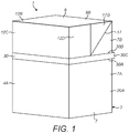
- a pack 1 for tobacco industry products according to a first embodiment of the invention is shown and comprises a body portion 2 and a lid portion 3 having a hinged attachment to one another.
- tobacco industry product refers to any item made in, or sold by the tobacco industry, typically including a) combustible smoking products such as cigarettes, cigarillos, cigars, tobacco for pipes or for roll-your-own cigarettes, (whether based on tobacco, tobacco derivatives, expanded tobacco, reconstituted tobacco or tobacco substitutes); b) non-combustible products incorporating tobacco, tobacco derivatives, expanded tobacco, reconstituted tobacco or tobacco substitutes such as snuff, snus, hard tobacco, and heat-not-burn products; and c) other nicotine-delivery systems such as inhalers, e-cigarettes, lozenges and gum.
- This list is not intended to be exclusive, but merely illustrates a range of products which are made and sold in the tobacco industry.
- the pack 1 is generally parallelepiped and comprises an outer frame 20A, forming the body portion 2 and the outer lid portion 3 and an inner frame 20B.
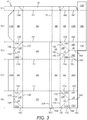
- a blank 10 for forming the outer frame 20A is shown in Figure 3 and a blank 21 for forming the inner frame 20B is shown in Figure 4 .
- the chain-dashed lines in Figures 3 and 4 denote fold lines and the solid lines denote cut lines.
- the double-dashed lines in Figures 3 and 4 denote lines of weakening, as will become apparent hereinafter.
- the inner frame 20B forms a collar portion 20C located at least partially within the body portion 2 and against which at least a portion of the lid portion 3 abuts when closed.
- the lid portion 3 includes a first top panel 9A, a second top panel 9B and lid side panels 6B, 7B.
- the first and second top panels 9A, 9B form at least part of a top wall 9 of the pack.
- the lid side panels 6B, 7B respectively form at least part of side wall 6,7 of the pack 1.
- the first top panel 9A and second top panel 9B have respective side edges which extend alongside the top edges of the lid side panels 6B, 7B.
- a sealing member 17 extends between the respective side edges of the top panel 9A and second top panel 9B and the top edge of the lid side panel 6B. In the present example, this sealing member 17 is folded upon itself and then down flat over the side wall 6 of the pack 1. Alternatively, the sealing member 17 can be folded upon itself and then over the top wall 9 of the pack 1.
- the sealing member 175 forms an air and/or moisture barrier between the inside and exterior of the pack 1, by sealing between the first top panel 9A, a second top panel 9B and a lid side panel 6B.
- the blank 10 forming the outer frame 20A of the pack 1 comprises a first bottom panel 8A that extends from the body front panel 4A and a second bottom panel 8B that extends from the body rear panel 5A.
- First and second sealing tabs 11A, 11B extend from the first and second bottom panels 8A, 8B respectively.
- Third and fourth sealing tabs 12A, 12B extend from the first and second top panels 9A, 9B respectively.
- a fifth sealing tab 12C extends from the fourth sealing tab 12B.
- a sealing flap 19 extends from the second bottom panel 8B, body rear wall 5A, lid read wall 5B, second top panel 9B and fourth sealing tab 12B, although it could, for instance, alternatively be provided along the opposite edge of the blank.
- Mechanised assembly of the outer frame 20A of the pack is facilitated by the division of the blank 10 for the outer frame 20A longitudinally into five laterally positioned sections S1 to S5 (see Figure 3 ) by first, second, third and fourth fold lines F1 to F4, which run in parallel along the whole length of the blank.
- Each of the sections S1 to S5 comprises a number of adjacent panels arranged laterally across the blank.
- the first section S1 comprises the sealing flap 19.
- the second section S2 is connected to the sealing flap 19 by the first fold line F1 and comprises the fourth and fifth sealing tabs 12B and 12C, the second top panel 9B, the lid rear panel 5B, the body rear panel 5A, the second bottom panel 8B and the second sealing tab 11B.
- the first sealing member 13 extends from respective side edges 13A, 13B of the first and second bottom panels 8A, 8B and a bottom edge 13C of the body side panel 6A.
- the sealing member 13 is integrally formed with the body side panel 6A and the first and second bottom panels 8A, 8B, and a fold line is formed along each edge 13A, 13B, 13C where the sealing member 13 meets the panels 6A, 8A, 8B.
- the panels S1-S5 of the blank 10 are folded relative to each other about their fold lines F1-F4 to form a hollow open-ended or tubular body having a cross section that, in this case, is rectangular, the panels S1-S4 extending between the open ends.
- the second sealing member 14 has a first fold line 14D which extends outwardly from where the bottom edge 14B of the body side panel 7A intersects the side edge 14A of the first bottom panel 8A.
- a second fold line 14E extends outwardly from where the bottom edge 14B of the body side panel 7A intersects with an edge 14C of the second sealing member 14 that opposes the side edge 14A of the first bottom panel 8A.
- the first and second fold lines 14D, 14E extend diagonally to meet at an edge of the second sealing member 14 that is remote from the body side panel 7A.
- the first and second fold lines 14D, 14E divide the second sealing member 14 into a first flap portion 14F that is proximate to the body side panel 7A, a second flap portion 14G that is remote to the first bottom panel 8A and a third flap portion 14H that is proximate to the first bottom panel 8A.
- the first and second flap fold lines 14D, 14E extend at angles of 45 degrees from the side edges 14A, 14C of the bottom panel 8A and second sealing member 14 respectively.
- the second sealing member 14 When the pack 1 is assembled, the second sealing member 14 is folded upon itself in a similar manner to the first sealing member 13 such that the side edge 14A of the first bottom panel 8A and the bottom edge 14B of the body side panel 7A are brought together and extend alongside one another, abutting each other in the present example.
- the first and third flap portions 14F, 14H are attached to each other and to the first bottom panel 8A using an adhesive as described above in relation to the corresponding components of the first sealing member 13. Therefore, the side edge 14A of the first bottom panel 8A and the bottom edge 14B of the body side panel 7A are retained in abutment with each other.
- the second bottom panel 8B and sealing flap 19 are folded relative to each other about the fold line between the two, and the second bottom panel 8B is folded relative to the body rear panel 5A.
- the side edge 14C of the second sealing member 14 and a side edge 19A of the second bottom panel 8B are brought together extend alongside one another, abutting each other in the present example.
- the first and second flap portions 14F, 14G are folded relative to each other about the second fold line 14E so that they abut or overlie each other.
- the third sealing member 15 extends from side edges 15A, 15B of the first and second top panels 9A, 9B and a top edge 15C of the lid side panel 6B.
- the third sealing member 15 is integrally formed with the lid side panel 6B and the first and second top panels 9A, 9B, and a fold line is formed along each edge 15A, 15B, 15C between the third sealing member 15 and the panels 6B, 9A, 9B.
- the third sealing member 15 has a first fold line 15D which extends outwardly from where the top edge 15C of the lid side panel 6B and the side edge 15A of the first top panel 9A intersect.
- a second fold line 15E extends outwardly from where the top edge 15C of the lid side panel 6B and the side edge 15B of the second top panel 9B intersect.
- the first and second fold lines 15D, 15E extend diagonally to meet at an edge of the third sealing member 15 that is remote from the lid side panel 6B.
- the first and second fold lines 15D, 15E divide the third sealing member 15 into a first flap portion 15F that is proximate to the lid side panel 6B, a second flap portion 15G that is proximate to the first top panel 9A and a third flap portion 15H that is proximate to the second top panel 9B.
- the first and second flap fold lines 15D, 15E extend at angles of 45 degrees from the side edges of the first and second top panels 9A, 9B respectively.
- the first and second flap portions 15F, 15G are attached to each other using an adhesive.
- the second top panel 9B and the lid side panel 6B are folded relative to each other about their fold lines with the lid rear panel 5B.
- the third sealing member 15 is folded upon itself, the side edge 15B of the second top panel 9B and the top edge 15C of the lid side panel 6B are brought together and extend alongside one another, abutting each other in the present example.
- the first and third flap portions 15F, 15H are folded relative to each other about the second fold line 15E so that they extend away from the second top panel 9B and the faces of the first and third flap portions 15F, 15H abut or overlie each other.
- the first and third flap portions 15F, 15H are attached to each other using an adhesive.
- the first and second fold lines 17D, 17E divide the sealing member 17 into a first flap portion 17F that is proximate to the lid side panel 7B, a second flap portion 17G that is remote to the first top panel 9A and a third flap portion 17H that is proximate to the first top panel 9A.
- the first and second flap fold lines 17D, 17E extend at angles of 45 degrees from the side edges 17A, 17C of the top panel 9A and sealing member 17 respectively.
- the sixth sealing member 18 has a fold line 18D which extends from an edge of the sealing member 18 that is remote to the fifth sealing member 17 to the point where the first and second fold lines 17D, 17E of the fifth sealing member 17 intersect.
- the fold line 18D divides the sixth sealing member 18 into a first flap portion 18E that is distal to the third sealing tab 12A and a second flap portion 18F that is proximate the third sealing tab 12A.
- the fold line 18D extends perpendicularly to the edge of the sixth sealing member 18 that is remote to the fifth sealing member 17.
- the sealing flap 19 abuts the first and second flap portions 17F, 17G, and the lid side panes 7B and is sealed thereto with an adhesive. Therefore, the side edge 17C of the fifth sealing member 17 and the side edge 19B of the second top panel 9B are retained in abutment with each other.
- the first and second top panels 9A, 9B meet each other and the third and fourth sealing tabs 12A, 12B fold outwardly and abut to form a second connecting flap 21B.
- the third and fourth sealing tabs 12A, 12B maybe sealed together using an adhesive.
- the side edges 16A, 16B of the third and fourth sealing tabs 12A, 12B meet and the fourth sealing member 16 folds upon itself along its fold line so that the first and second flap portions 16E, 16F extend away from the second connecting flap 21B and the faces of the first and second flap portions 16E, 16F abut each other.
- the first and second flap portions 16E, 16F are held together with adhesive to restrict or prevent air and/or moisture from entering or leaving the pack between the edges 16A, 16B of the third and fourth sealing tabs 12A, 12B.
- the side edge 18C of the sixth sealing member 18 meets a side edge 19C of the second sealing tab 12B and the sixth sealing member 18 folds upon itself along its fold line 18D so that the first and second flap portions 18E, 18F extend away from the second connecting flap 21B and the faces of the first and second flap portions 18E, 18F abut each other.
- the first and second flap portions 18E, 18F are held together with adhesive and the first flap portion 18E abuts the flap 19 and is secured thereto by an adhesive to restrict or prevent air and/or moisture from entering or leaving the pack 1 between the edges 18A, 19C of the third and fourth sealing tabs 12A, 12B.
- the second connecting flap 21B is folded so that it abuts the first top panel 9A and is sealed thereto with an adhesive.
- the first flap portion 16E of the fourth sealing member 16 is brought together with and abuts the second flap portion 15G of the third sealing member 15 and is sealed thereto using an adhesive so that the first, second and third flap portions 15F, 15G, 15H of the third sealing member 15 and the first and second flap portions 16E, 16F of the fourth sealing member 16 all lie substantially coplanar.
- the first, second and third flap portions 15F, 15G, 15H of the third sealing member 15 and the first and second flap portions 16E, 16F of the fourth sealing member 16 are then all folded about the top edge 15C of the lid side panel 6B so that they overlap the lid side panel 6B.
- the first flap portion 15F is sealed to the lid side panel 6B using an adhesive.
- the second flap portion 18F of the sixth sealing member 18 is brought together with and abuts the third flap portion 17H of the fifth sealing member 17 and is sealed thereto using an adhesive so that the first, second and third flap portions 17F, 17G, 17H of the fifth sealing member 17 and the first and second flap portions 18E, 18F of the sixth sealing member 18 all lie substantially coplanar.
- the first, second and third flap portions 17F, 17G, 17H of the fifth sealing member 17 and the first and second flap portions 18E, 18F of the sixth sealing member 18 are then all folded about the top edge 17B of the lid side panel 7B so that they overlap the lid side panel 7B.
- the first flap portion 17F is sealed to the lid side panel 7B using an adhesive.
- the fifth sealing tab 12C extends from the second connecting flap 21B and is folded so that it abuts the lid front panel 4B and is secured thereto with an adhesive.
- Sixth and seventh sealing tabs 12D, 12E extend from opposing ends of the fifth sealing tab 12C and are folded so that they abut the first flap portion 18E of the sixth sealing member 18 and the second flap portion 16F of the fourth sealing member 16 respectively and are each sealed thereto with an adhesive.
- the fifth, sixth and seventh sealing tabs 12C, 12D, 12E may improve the strength and rigidity of the lid portion 3 and/or may provide an additional layer of barrier material to restrict or prevent the transfer of air/moisture into or out of the pack.
- the first, second and third flap portions 15F, 15G, 15H of the third sealing member 15, the first and second flap portions 16E, 16F of the fourth sealing member 16, the first, second and third flap portions 17F, 17G, 17H of the fifth sealing member 17 and the first and second flap portions 18E, 18F of the sixth sealing member 18 are all on the outside surface of the lid portion 3.
- a cut does not extend between any of the side edges 13A, 13B, 14A, 15A, 15B, 16A, 19A, 19B of the first and second bottom and top panels 8A, 8B, 9A, 9B and the body side panel 6A, 7A bottom edges 13C, 14B and lid side panel 6B, 7B top edges 15C, 16B that abut when the blank 10 is folded to construct the pack. Therefore, the transfer of air and/or moisture into or out of the pack 1 can be at least partially restricted, or prevented.
- the tear-off strip 30 has an end 30C that extends past an end of the body and lid side panels 7A, 7B so that the tear-off strip 30 may be gripped by the user at the end 30C to separate the lid portion 3 from the body portion 2.
- the inner frame 20B comprises a top panel 22A that is integrally formed with a rear panel 23A, front panel 24A and side panels 25A, 25B that each extend from an opposing edge of the top panel 22A. Fold lines are formed between the top panel 22A and each of the rear, front and side panels 23A, 24A, 25A, 25B. First sealing panels 26A, 26B and second sealing panels 26C, 26D extend from opposing edges of the side panels 25A, 25B. A strengthening rear panel 23B extends from the rear panel 23A and a fold line 27A is formed therebetween.
- a strengthening top panel 22B extends from the strengthening rear panel 23B and is integrally formed with a strengthening front panel 24B and strengthening side panels 25C, 25D which each extend from opposing edges of the strengthening top panel 22B. Fold lines are formed between the strengthening top panel 22B and each of the strengthening rear, front and side panels 23B, 24B, 25C, 25D.
- the strengthening rear panel 23B is folded relative to the rear panel 23A along the fold line 27A so that the rear panel 23A and strengthening rear panel 23B are brought together and abut each other.
- the top panel 22A and strengthening top panel 22B will be brought together and the front and side panels 24A, 25A, 25B will be brought together with corresponding strengthening front and side panels 24b, 25C, 25D so that the fold lines between the top panel 22A and rear, front and side panels 23A, 24A, 25A, 25B and the fold lines between the strengthening top panel 22B and strengthening rear, front and side panels 23B, 24B, 25C, 25D overlap.
- the rear panel 23A and side panels 25A, 25B are then folded relative to each other about their fold lines with the lid top panel 22A so that the side panels 25A, 25B face each other.
- the front panel 24A is then folded relative to the top panel 22A along its fold line so that it faces the rear panel 23A.
- the strengthening rear and front panels 23B, 24B will also face each other, as will the strengthening side panels 25C, 25D so that the inner frame 20B has a double layered structure.
- the doubled layered structure of the inner frame 20B improves the strength and rigidity of the inner frame 20B.
- the first sealing flaps 26A, 26B are folded relative to the side panels 25A, 25B about their respective fold lines so that they abut the rear panel 23A or strengthening rear panel 23B and are sealed thereto by an adhesive to prevent the ingress of air and/or moisture between the rear panel 23A and side panels 25A, 25B.
- the second sealing flaps 26C, 26D are folded relative to the side panels 25A, 25B about their respective fold lines so that they abut the front panel 24A and/or strengthening front panel 24B and are sealed thereto by an adhesive to prevent the ingress of air and/or moisture between the front panel 24A and side panels 25A, 25B.
- adhesive may also be provided between the top, rear, front and side panels 22A, 23A, 24A, 25A, 25B and the respective strengthening top, rear, front and side panels 22B, 23B, 24B, 25C, 25D to improve the strength and rigidity of the inner frame 20B.
- a first line of weakening 28A is formed in the top panel 22A and extends from the fold line 27B between the top and rear panels 22A, 23A to the front panel 24A and then back to the fold line 27B, so that the line of weakening 28A runs between opposing ends of the top panel 22A.
- the portion of the top and front panels 22A, 24A between the first line of weakening 28A and the fold line 27B forms a first lid flap 29A.
- the fold line 27B forms a first lid flap 29A hinge.
- a second line of weakening 28B is formed in the strengthening top panel 22B and extends from the fold line 27C between the strengthening top and rear panels 22B, 23B to the strengthening front panels 23B and then back to the fold line 27C, so that the line of weakening 28B runs between opposing ends of the strengthening top panel 22B.
- the portion of the strengthening top panel 22A between the line of weakening 28B and the fold line 27C forms a second lid flap 29B.
- the first and second lid flaps 29A, 29B are held together by an adhesive to form an inner frame lid 29.
- the surface area of the first lid flap 29A is larger than the surface area of the second lid flap 29B so that the edges of the first lid flap 29A overlie a portion 22C of the strengthening top panel 22B forming a shoulder.
- the portion of the first lid flap 29A that is formed from the front panel 24A comprises an opening portion 29C that overlies the strengthening front panel 24B when the inner frame lid 29 is closed.
- the opening portion 29C is folded along a fold line 27D so that when the inner frame lid 29 is closed a section of the opening portion 29C protrudes from the surface of the front panel 24A and forms a tab 29D.
- the tab 29D may be gripped by the user to open the inner frame lid 29 or may enable the user to slide a fingernail under the opening portion 29C to open the inner frame lid 29.
- the opening portion 29C of the inner lid 29 is folded along a fold line 27D so that a tab 29D is formed that may be gripped by the user to open the pack
- the tab 27D is omitted and is replaced by an aperture that is formed in the front panel 24A.
- a user may position a finger in the aperture to slide a fingernail under the opening portion 29C to facilitate opening of the inner lid 29.
- the inner frame 20B is attached to the outer frame 20A of the pack 1 by using adhesive to glue the front, rear and side panels 24A, 23A, 25A, 25B of the inner frame 20B to the inside surface of the body front, rear and side panels 4A, 5A, 6A, 7A of the outer frame 20A.
- the inner frame 20B forms a collar portion 20C against which the lid portion 3 of the pack 1 abuts when the lid portion 3 is closed.
- the front, rear and side panels 24A, 23A, 25A, 25B of the inner frame 20B extend above the corresponding front, rear and side panels 4A, 5A, 6A, 7A of the body to which they are adhered, and so extend out of the outer frame 2oB when the lid portion 3 is open and lie within the lid portion 3 when it is closed.
- the top portion of the inner frame 20B may lie flush with or just below the upper edge of the body portion.
- the lid portion 3 does not overlie the inner frame 20B when the lid portion 3 is closed.
- the user pulls on the end 30C of the tear-off strip 30 so that the body front and side panels 4A, 6A, 7A are separated from respective front and side panels 4B, 6B, 7b of the lid portion 3.
- the lid portion 3 is then pivoted about the hinge line 31 to reveal the inner frame 20B.
- the user then breaks the lines of weakening 28A, 28B of the inner frame lid 29 so that the first and second lid flaps 29A, 29B are free to move together about their respective fold lines 27B, 27C so that the inner frame lid 29 can be pivoted open to access the contents of the pack 1.
- the inner lid 29 provides an extra barrier of material to prevent the transfer of air and/or moisture into and/or out of the pack 1. Furthermore, when the tear-off strip 30 has been removed, there may be a gap between the lid portion 3 and the body portion 2 or inner frame 20B which may allow for the transfer of air and/or moisture into or out of the pack 1. The inner lid 29 inhibits this transfer of air and/or moisture to help keep the contents of the pack fresh after the tear-off strip has been removed.
- the walls of the outer and inner frames 20A, 20B may each have one face that comprises the stiff material, which is easily printed on, and an opposing face, comprising the MET-PET and PE that has a metalized effect that may be pleasing to the eye and/or provide an air/moisture barrier.
- the faces of the walls of the outer frame 20A that have the metalized effect may face inwardly, towards the contents of the pack 1, so that the metalized effect is only visible to the user when the lid portion 3 of the pack 1 is in the open position.
- the faces of the panels of the inner frame 20B that have the metalized effect may face outwardly, in a direction away from the contents of the pack, so that the metalized effect is visible to the user when the lid portion 3 of the pack is in the open position.
- the metalized effect of the inside surface of the lid portion 3 corresponds to the metalized effect of the outer surface of the inner frame 20B.
- the faces of the walls of the outer frame 20A that face inwardly, towards from the contents of the pack, and the faces of the panels of the inner frame 20B that face outwardly, away from the contents of the pack comprise the stiff material that is easily printable.
- the faces of the panels of the inner fame 20B that face outwardly, away from the contents of the pack, and the faces of the strengthening panels of the inner frame 20B that face inwardly, towards the contents of the pack have the metalized effect.
- a pack according to a second embodiment of the invention is shown and is similar to the pack of the first embodiment of the invention, with like features retaining the same reference numerals.
- the pack 1 of the second embodiment of the invention is formed from the same blank 10 (shown in Figures 3 and 4 ) as the first embodiment of the invention, and the bottom wall 8 of the pack 1 comprises first and second bottom panels 8A, 8B and the top wall 9 of the pack 1 comprises first and second top panels 9A, 9B.
- a side edge 13A, 13B, 14A, 15B, 16A, 17A, 19A, 19B of each of the first and second bottom panels 8A, 8B and/or each of the first and second top panels 9A, 9B abuts an edge 13C, 14B, 15C, 17B of a body side panel 6A, 7A and/or lid side panel 6B, 7B.
- a flap of material extends between said edges and forms a sealing member (described in more detail hereinafter) that partially restricts, or prevents, the transfer of air and/or moisture into or out of the pack 1 between said edges.
- a difference between the first and second embodiments of the invention is that the panels of the blank 10 that form the lid portion 3 are folded differently to construct the pack of the second embodiment.
- the first top panel 9A and lid side panel 6B are folded relative to each other about their fold lines with the lid front panel 4B.
- the third sealing member 15 is folded upon itself so that side edge 15A of the first top panel 9A and the top edge 15C of the lid side panel 6B are brought together and extend alongside one another, abutting each other in the present example.
- the first and second flap portions 15F, 15G are folded relative to each other about the first fold line 15D so that they return back alongside the first top panel 9A and the faces of the first and second flap portions 15F, 15G abut or overlie each other.
- the second flap portion 15G is attached to the first top panel 9A and the first and second flap portions 15F, 15G are attached to each other using an adhesive. Therefore, the side edge 15A of the first bottom panel 9A and the top edge 15C of the lid side panel 6B are retained in abutment with each other. Similarly, the second top panel 9B and lid side panel 6B are folded relative to each other about their fold lines with the lid rear panel 5B. As the third sealing member 15 is folded upon itself, the side edge 15B of the second top panel 9B and the top edge 15C of the lid side panel 6B are brought together and extend alongside one another, abutting each other in the present example.
- the first and third flap portions 15F, 15H are folded relative to each other about the second fold line 15E so that they return back alongside the second top panel 9B and the faces of the first and third flap portions 15F, 15H abut each other.
- the third flap portion 15H is attached to the second top panel 9B and the first and third flap portions 15F, 15H are attached to each other, using an adhesive. Therefore, the side edge 15B of the second top panel 9B and the top edge 15C of the lid side panel 6B are retained in abutment with each other.
- the first top panel 9A and lid side panel 7B are folded relative to each other about their fold lines with the lid front panel 4B.
- the fifth sealing member 17 is folded upon itself so that the side edge 17A of the first top panel 9A and the top edge 17B of the lid side panel 7B are brought together and extend alongside one another, abutting each other in the present example.
- the first and third flap portions 17F, 17H are folded relative to each other about the first fold line 17D so that they return back alongside the first top panel 9A and the faces of the first and third flap portions 17F, 17H abut each other.
- the third flap portion 17H is attached to the first top panel 9A and the first and third flap portions 17F, 17H are attached to each other, using an adhesive. Therefore, the side edge 17A of the first top panel 9A and the top edge 17B of the lid side panel 7B are retained in abutment with each other. Similarly, the second top panel 9B and sealing flap 19 are folded relative to each other about their fold lines with the lid rear panel 5B. As the fifth sealing member 17 is folded upon itself, thee side edge 17C of the fifth sealing member 17 and a side edge 19B of the second lid panel 9B are brought together and extend alongside one another, abutting each other in the present example.
- the first and second flap portions 17F, 17G are folded relative to each other about the second fold line 17E so that they return back alongside the second top panel 9B and the faces of the first and second flap portions 17F, 17G abut each other.
- the second flap portion 17G is attached to the second top panel 9B and the first and second flap portions 17F, 17G are attached to each other, using an adhesive.
- the sealing flap 19 abuts the first and second flap portions 17F, 17G, and the lid side panel 7B and is sealed thereto with an adhesive. Therefore, the side edge 17C of the fifth sealing member 17 and the side edge 19B of the second top panel 9B are retained in abutment with each other.
- the first and second top panels 9A, 9B meet each other and the third and fourth sealing tabs 12A, 12B abut to form a second connecting flap 21B.
- the third and fourth sealing tabs 12A, 12B abut, the side edges 16A, 16B of the third and fourth sealing tabs 12A, 12B meet and the fourth sealing member 16 folds along its fold line 16D so that the faces of the first and second flap portions 16E, 16F abut each other.
- the first and second flap portions 16E, 16F are held together with adhesive to at least substantially prevent air and/or moisture from entering or leaving the pack between the edges 16A, 16B of the third and fourth sealing tabs 12A, 12B.
- the side edge 18C of the sixth sealing member 18 meets a side edge 19C of the second sealing tab 12B and the sixth sealing member 18 folds along its fold line 18D so that the faces of the first and second flap portions 18E, 18F abut each other.
- the first and second flap portions 18E, 18F are held together with adhesive and the first flap portion 18E abuts the flap 19 and is secured thereto by an adhesive to at least substantially prevent air and/or moisture from entering or leaving the pack 1 between the edges 18A, 19C of the third and fourth sealing tabs 12A, 12B.
- the second connecting flap 21B is folded so that it abuts the first top panel 9A and is sealed thereto with an adhesive.
- the fifth sealing tab 12C extends from the second connecting flap 21B and is folded so that it abuts the lid front panel 4B and is secured thereto with an adhesive.
- Sixth and seventh sealing tabs 12D, 12E extend from opposing ends of the fifth sealing tab 12C and are folded so that they abut opposing lid side panels 6B, 7B and are secured thereto with an adhesive.
- the fifth, sixth and seventh sealing tabs 12C, 12D, 12E may improve the strength and rigidity of the lid portion 3.
- the first, second and third flap portions 15F, 15G, 15H of the third sealing member 15, the first and second flap portions 16E, 16F of the fourth sealing member 16, the first, second and third flap portions 17F, 17G, 17H of the fifth sealing member 17 and the first and second flap portions 18E, 18F of the sixth sealing member 18 are all on the inside surface of the lid portion 3.
- a cut does not extend between any of the side edges 13A, 13B, 14A, 15A, 15B, 16A, 19A, 19B of the first and second bottom and top panels 8A, 8B, 9A, 9B and the body side panel 6A, 7A bottom edges 13C, 14B and lid side panel 6B, 7B top edges 15C, 16B that abut when the blank 10 is folded to construct the pack. Therefore, the transfer of air and/or moisture into or out of the pack 1 can be at least partially restricted, or prevented.
- a pack 1 according to a third embodiment of the invention is shown and is similar to the pack of the first embodiment of the invention, with like features retaining the same reference numerals.
- the pack 1 of the third embodiment of the invention is formed from the same blank 10 (shown in Figures 3 ) as the first embodiment of the invention, which is folded in the same manner as the first embodiment of the invention.
- a difference between the first and third embodiments of the invention is that the inner frame 20B of the pack 1 of the first embodiment is omitted and is replaced by an alternative inner frame 40.
- the inner frame 40 of the pack of the third embodiment of the invention is a moulding made from a plastics material and forms a collar portion that is located partially within the body portion 2 and against which at least a portion of the lid portion 3 abuts when closed.
- the inner frame 40 comprises a top panel 42 that is integrally formed with a rear panel 43, front panel 44 and side panels 45A, 45B that each extend from an opposing edge of the top panel 42.
- An aperture 46 is formed in the top panel 42 and allows access to the contents of the pack 1.
- the inner frame 40 further comprises an inner lid 47 that is hingedly connected to the collar portion and is received in the aperture 46 when the inner lid 47 is closed to seal the pack contents.
- the inner lid 47 provides an additional barrier to protect the contents of the pack 1 from air and/or moisture.
- the inner lid 47 comprises a lip 47A that is received against the inner frame 40 at the periphery of the aperture 46 when the inner lid 47 is closed to improve the seal between the inner lid 47 and the top panel 42.
- the lip 47A increases the contact area between the inner lid 47 and the collar portion and so prevents unintentional opening of the inner lid 47 during transit of the pack 1.
- the inner lid 47 comprises a tab 48 that extends from a portion of the edge of the inner lid 47 that is proximate to the front panel 44 of the inner frame 40 when the inner lid 47 is closed.
- the tab 48 is received in a recess 49 in the front panel 44 when the inner lid 47 is closed.
- the friction between the tab 48 and the front panel 44 prevents unintentional opening of the inner lid 47.
- the user may slide a fingernail between the tab 48 and the front panel 44 to open the inner lid 47.
- the plastic moulded inner frame 40 can be made to be more durable than the inner frame 20B of the first embodiment of the invention that is folded from a blank of material.
- the inner frame 40 of the third embodiment can have an increased rigidity and so can better protect the pack contents and allow for the inner lid 47 to more securely fit into the collar portion so that the inner lid 47 remains closed when the pack 1 is not in use. Therefore, the inner frame 40 of the third embodiment of the invention, in some examples, does not require adhesive to keep the inner lid 47 closed during transit.
- a pack 1 having the inner frame 40 of the third embodiment can include resealable adhesive to further improve the seal provided by the inner frame 40.
- the inner frame 50 of the pack of the fourth embodiment of the invention is a moulding made from a plastics material and forms a collar portion that is located partially within the body portion of the pack and against which at least a portion of the lid portion of the pack abuts when closed.
- the inner frame 50 comprises a top panel 52 that is integrally formed with a rear panel 53, front panel 54 and side panels 55A, 55B that each extend from an opposing edge of the top panel 52.
- the inner frame 50 further comprises an inner lid 57 that is hingedly connected to the collar portion and is received in the aperture 56 when the inner lid 57 is closed to seal the pack contents.
- the inner lid 57 provides an additional barrier to protect the contents of the pack from air and/or moisture.
- the inner lid 57 comprises a lip 57A that is received against the inner frame 50 at the periphery of the aperture 56 when the inner lid 57 is closed to improve the seal between the inner lid 57 and the top panel 52.
- the lip 57A increases the contact area between the inner lid 57 and the collar portion and so prevents unintentional opening of the inner lid 57 during transit of the pack.
- the inner lid 57 comprises a tab 58 that extends from the edge of the inner lid 57 that is proximate to the front panel 54 of the inner frame 50 when the inner lid 57 is closed.
- the tab 58 is received in a recess 59 in the front panel 54 when the inner lid 57 is closed. The friction between the tab 58 and the front panel 54 prevents unintentional opening of the inner lid 57.
- the front panel 54 of the inner frame 50 comprises an indent 54A that is proximate to the recess 59.
- the indent 54A enables the user to easily slide a fingernail between the tab 58 and the front panel 54 to open the inner lid 57.
- the tab 58 of the inner frame 50 of the fourth embodiment extends along the entire edge of the inner lid 57 that is proximate the front panel 54. Therefore, the contact area between the tab 58 and the front panel 54 is increased to increase friction therebetween when the inner lid 57 is closed.
- the top panel 52 comprises side portions 52A, 52B, which are adjacent to the respective side panels 55A, 55B of the inner frame 50, and a front portion 52C that is adjacent to the front panel 54 of the inner frame 50.
- the inner lid 57 overlies the front portion 52C of the top panel 52 when closed.
- the front portion 52C of the top panel 52 is depressed slightly relative to the side portions 52A, 52B of the top panel 52 such that, when the inner lid 57 is closed to overlie the front portion 52C, the inner lid 57 and the side portions 52A, 52B of the top panel 52 form a flat surface.
- the width W 1 of the front portion 52C of the top panel 52 is smaller than the width W2 of each of the side portions 52A, 52B of the top panel 52 such that the width W 1 of the front portion 52C of the inner frame 50 is smaller than that of the front portion of the top panel of the inner frame 40 of the third embodiment of the invention.
- the decreased width W 1 of the front portion 52C of the top panel 52 of the inner frame 50 of the fourth embodiment allows for an increased size of aperture 56 to enable the pack contents to be accessed more easily when the inner lid 57 is open. Furthermore, there is less chance of the pack contents being caught behind the front portion 52C of the top panel 52 when the pack is tipped to empty the contents of the pack onto a surface.
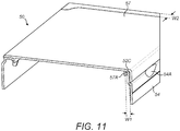
- the front portion 52C of the top panel 52 When the inner lid 57 is closed, the front portion 52C of the top panel 52 is located between the lip 57A and the tab 58 of the inner lid 57, as can be seen from Figure 11 .
- the width W1 of the front portion 52C of the top panel 52 is slightly larger than the distance between the lip 57A and tab 58 of the inner lid 57 such that when the inner lid 57 is closed the front portion 52C of the top panel 52 is compressed between the lip 57A and tab 58 to hold the inner lid 57 in the closed position.
- the inner frame 50 of the pack of the fourth embodiment can be made to be more durable than the inner frame 20B of the first embodiment of the invention that is folded from a blank of material.
- the inner frame 50 of the fourth embodiment can have an increased rigidity and so can better protect the pack contents and allow for the inner lid 57 to more securely fit into the collar portion so that the inner lid 57 remains closed when the pack is not in use.
- the inner frame 40, 50 is manufactured from a single material
- the inner lid is manufactured from multiple materials.
- the collar portion is manufactured from moulded plastic and the inner lid is manufactured from a flap of card that is bonded to the collar portion using adhesive.
- the pack 1 is described as having fourth and sixth sealing member flaps 16, 18, in an alternative embodiment (not shown) the members 16, 18 maybe omitted and instead air and/or moisture is prevented from entering or leaving the pack by the first, second, third and fifth sealing members 13, 14, 15, 17.
- the pack 1 comprises a lid portion 3 that is hingedly attached to the body portion 2 of the pack 1, in an alternative embodiment (not shown) the lid is detachable from the body portion of the pack when the pack is opened.
- the body front and rear panels are connected to the lid front and rear panels respectively and the body side panels are connected to respective lid side panels by a tear-off strip when the pack is in the closed position after being assembled.
- the user grips an end of the tear-off strip and pulls the tear-off strip along lines of weakening so that the tear-off strip no longer connects the respective lid and body panels of the pack.
- the lid portion may be removed from the body portion to expose the inner frame.
- the contents of the pack may then be accessed by opening the inner lid, which can then be closed to reseal the pack contents.
- Such an arrangement allows for the lid portion to seal the pack contents prior to the first opening of the pack.
- the lid portion can then be removed when the pack is first opened to decrease the size of the pack.
- the pack 1 comprises a single inner lid 29, 47
- the pack comprises a plurality of inner lids.
- the inside of the body portion of the pack 1 is partitioned into a plurality of internal compartments by a dividing wall and each of the plurality of inner lids covers a respective internal compartment. Therefore, one compartment may be opened and the contents stored therein consumed before the next compartment is opened, to increase the perceived freshness of the pack contents.
- the inner lid 29, 47 is rigid and is hingedly attached to the inner frame 20B, 40
- the inner lid comprises a portion of flexible material that is sealed to the top panel of the inner frame by a resealable adhesive.
- the portion of flexible material comprises a flap that is hingedly attached to the inner frame such that the flexible material maybe partially removed from the inner frame to access the contents of the pack.
- the portion of flexible material is completely detachable from the inner frame to access the contents of the pack and may be reattached to the inner frame using the resealable adhesive to reseal the pack.
- the inner frame comprises a rigid inner lid and a portion of flexible material that is sealed to the top of the panel of the inner frame to provide an additional barrier to prevent the ingress of air and/or moisture into the pack.
- the pack 1 comprises a lid portion 3 that covers the inner frame 20B, 40 when closed, in an alternative embodiment (not shown) the lid portion is omitted.
- an inner membrane is included beneath the inner lid to prevent the ingress of air or moisture into the pack.
- the inner membrane comprises an impermeable material that is penetrated on first opening of the inner lid to provide access to the pack contents.
- impermeable materials include card or a flexible material, for example, plastic or foil or a combination thereof.
- the flexible material comprises aluminium foil that is laminated with a plastic material.
- One or more lines of weakening may be provided in the inner membrane to aid in penetration of the inner membrane.
- the inner membrane may allow for the contents of the pack to be hermetically sealed even in the event that there are gaps between the inner lid and the front or top panel of the inner frame, for example, due to manufacturing tolerances.
- the inner frame has a second lid flap 29B
- the second lid flap 29B may be omitted and replaced with an aperture in the strengthening top panel 22B.
- the pack 1 is described as comprising fifth, sixth and seventh sealing tabs 12C, 12D, 12E, in alternative embodiments (not shown) one or more of these sealing tabs 12C, 12D, 12E may be omitted.
- the pack 1 is described as comprising a fifth sealing tab 12C that extends from the fourth sealing tab 12B, in alternative embodiments (not shown) the fifth sealing tab 12C may extend from the first, second or third sealing tabs 11A, 11B, 12A. In yet another embodiment (not shown), the fifth sealing tab may be omitted.
- the tear strip 30 has been described as being formed from first and second lines of weakening, alternatively a single line of weakening can be used, and/or a tear string or other additional component can be provided to aid in separating the lid portion 3 from the body portion 2 of the pack 1.
- the additional component may, for instance, be provided on an inner surface of the pack wall, or within the laminated structure of the pack wall.
- the outer surface of the pack wall overlying or adjacent to the additional component maybe weakened, for instance with cuts partially through the thickness of the pack wall, or other forms of weakening such as scoring, to aid in opening the pack 1 using the tear strip.
- a tamper evident device may be provided on the inner lid.
- the tamper evident device may comprise a portion of material that is secured to the inner lid and collar portion and is torn or deformed when the inner lid is opened.
- the tamper evident device comprises a sticker that is adhered to the inner lid and collar portion of the inner frame. The sticker is torn the first time the inner lid is opened and therefore provides a visual indication to the user as to whether the pack contents have previously been accessed.
- a label (not shown) may be provided on the inner lid. Therefore, when the user opens the lid portion of the pack, the label is revealed.
- the label may comprise, for example, advertising or information about the contents of the pack.
- the label is provided on the inner lid using in-mould labelling.
- the label may comprise, for example, a sticker that is adhered to the inner lid.
Description
- The invention relates to a pack, particularly but not exclusively to a pack for tobacco industry products. The invention also relates to a blank for the pack and to a method of assembling a pack.
- Packaging for containing tobacco industry products such as loose 'Roll Your Own' (RYO) or 'Make Your Own' (MYO) tobacco, or other similar products, often comprises a pouch or bag formed of a flexible sheet material such as polyethylene. A pack with a body and a lid being formed from a blank and comprising tab-type sealing members at the pack ends is disclosed by
DE 44 29 095 A1 - According to the invention, there is provided a pack comprising: a lid portion; a body portion; a collar portion located at least partially within the body portion and against which at least a portion of the lid abuts when closed; first, second and third panels, wherein the first and second panels form at least part of a first wall of the pack and the third panel forms at least part of a second wall of the pack, and wherein the first, second and third panels have respective first, second and third edges and the first and second edges extend alongside and/or abut the third edge; and, a sealing member extending between the first, second and third edges of the pack, wherein the body portion and lid portion provide an airtight seal until the lid portion is first opened. The sealing member may be folded to overlap the first or second wall of the pack. The sealing member may be integrally formed with the first, second and third panels.
- The sealing member may comprise first and second fold lines that extend from corners of the sealing member that are proximate to the third panel to meet at an edge of the sealing member that is remote of the third panel. In one such embodiment, the first and second fold lines separate the sealing member into first, second and third portions and the first and second of these portions lie against the third portion.
- A sealing tab may extend from the first panel and a second sealing tab may extend from the second panel. In one such embodiment, the first and second sealing tabs are connected together to form a connecting flap and a third sealing tab may extend from the connecting flap. In an alternative embodiment, the first sealing tab overlies the second panel and the second sealing tab overlies the first panel.
- An auxiliary sealing member may extend from the sealing member and the first and second sealing tabs.
- In one embodiment, the sealing member comprises a first sealing member, the pack further comprising fourth, fifth and sixth panels, wherein the fourth panel forms at least part of the second wall of the pack and the fifth and sixth panels form at least part of a third wall of the pack that opposes the first wall, and wherein the fourth, fifth and sixth panels have respective fourth, fifth and sixth edges and the fifth and sixth edges extend alongside and/or abut the fourth edge; and a second sealing member extending from each of the fourth, fifth and sixth edges and folded to underlie the third wall of the pack.
- The pack may comprise a tear-off strip that is attached to the lid and body portions of the pack and may be removed from the pack to separate at least a section of the lid from the body. In one embodiment, the tear-off strip may be removed from the pack to completely separate the lid from the body. The tear-off strip may be formed from two lines of weakening in the pack material.
- The pack may comprise an inner lid connected to the collar portion. The lid and/or inner lid may be composed of a plastics material and may be moulded. Alternatively, the lid and/or inner lid may comprise card or a flap of flexible material. The pack may comprise a plurality of inner lids. In one such embodiment, the body portion is divided into a plurality of internal compartments and each compartment is coverable by a respective one of the plurality of inner lids.
- The pack may comprise an inner frame that comprises front, rear and side panels, wherein the inner frame is disposed within the body of the pack and projects out of an opening therein to form the collar portion. The inner frame may comprise a top panel with the inner lid formed in the top panel. At least one of the front, rear, top and side panels can be formed from a double layer of material and at least two of the front, rear, top and side panels can be integrally formed. The inner frame may be composed of a plastics material and may be moulded. In one embodiment, the inner frame further comprises laminated card.
- In one embodiment, the top panel comprises side portions and a front portion and wherein the width of the front portion is less than the width of the side portions.
- In one embodiment, the inner lid comprises a lip. The inner lid may be configured such that the front panel and/or top panel abuts the lip when the inner lid is in a closed position.
- In one embodiment, the or each inner lid comprises a tamper evident device. The or each tamper evident device may comprise a portion of material that is secured to the inner lid and collar portion and is torn or deformed when the inner lid is opened.
- In one embodiment, the or each inner lid comprises a label. The label may be provided on the inner lid by in-mould labelling.
- In one embodiment, the pack comprises an inner membrane configured to hermetically seal the pack
The pack panels may comprise an impermeable and water resistant material and the impermeable and water resistant material may be laminated card. The laminated card can comprise a layer of polyester with a metalized surface and a polyethylene (PE) layer. The present disclosure also provides a blank for forming a pack according to the invention. - According to another aspect of the invention, there is also provided a method of assembling a pack having a plurality of adjacent side faces, and opposing end faces defining a chamber for containing a product, the method comprising: folding a flat blank longitudinally to form a hollow open-ended body having a plurality of adjacent panels extending between the open ends of the body, each panel being connected to at least one adjacent panel by a fold line forming a side edge of the pack between the adjacent panels; assembling a tubular collar portion on one end of the body; folding connected end portions of adjacent first and second panels along respective fold lines that form end edges of the pack, whereby the end portion of one panel forms an end panel of the pack, and folding the end portion of the other panel upon itself to form a seal between the first and second panels, such that the end portion of said other panel comprises a sealing member.
- In one such embodiment, sealing member comprises first, second and third flap portions that each comprise an inner surface, and wherein the step of folding the end portion of the first panel upon itself comprises folding the sealing member such that inner surfaces of the second and third flap portions overlie the inner surface of the first flap portion. In an alternative embodiment, the sealing member comprises first, second and third flap portions that each comprise an outer surface, and wherein the step of folding the end portion of the first panel upon itself comprises folding the sealing member such that outer surfaces of the second and third flap portions overlie the outer surface of the first flap portion.
- The end portion of the second panel may comprise the end panel.
- In one embodiment, the step of folding the connected end portions of the first and second panels along the respective fold lines that form end edges of the pack comprises folding the end panel such that it overlies the first flap portion and the second or third flap portion of the sealing member.
- In one embodiment, the step of folding the connected end portions of the first and second panels along the respective fold lines that form end edges of the pack comprises folding the end panel such that it is substantially coplanar with the first, second and third flap portions of the sealing member.
- Embodiments of the invention will now be described, by way of example only, with reference to the accompanying drawings in which:
-
Figure 1 is a perspective view of a pack in accordance with a first embodiment of the invention in a closed position; -
Figure 2 is a perspective view of the pack ofFigure 1 in an open position, with an open inner lid; -
Figure 3 is a top view of a blank of an outer frame of the pack ofFigure 1 ; -
Figure 4 is a top view of a blank of an inner frame of the pack ofFigure 1 on an enlarged scale compared withFigure 3 ; -
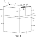
Figure 5 is a perspective view of a pack in accordance with a second embodiment of the invention in a closed position; -
Figure 6 is a perspective view of the pack ofFigure 5 in an open position, with an open inner lid; -
Figure 7 is a perspective view of a pack in accordance with a third embodiment of the invention in an open position, with an open inner lid; and, -
Figure 8 is a perspective view of the pack ofFigure 7 in an open position, with a closed inner lid; -
Figure 9 is a perspective view from above of an inner frame of a pack according to a fourth embodiment of the invention, with a closed inner lid; -
Figure 10 is a perspective view from above of the inner frame ofFigure 9 , with an open inner lid; and, -
Figure 11 is a cross-sectional perspective view from the side of the inner frame ofFigure 9 . - Referring to
Figures 1 and2 , apack 1 for tobacco industry products according to a first embodiment of the invention is shown and comprises abody portion 2 and alid portion 3 having a hinged attachment to one another. - As used herein, the term "tobacco industry product" refers to any item made in, or sold by the tobacco industry, typically including a) combustible smoking products such as cigarettes, cigarillos, cigars, tobacco for pipes or for roll-your-own cigarettes, (whether based on tobacco, tobacco derivatives, expanded tobacco, reconstituted tobacco or tobacco substitutes); b) non-combustible products incorporating tobacco, tobacco derivatives, expanded tobacco, reconstituted tobacco or tobacco substitutes such as snuff, snus, hard tobacco, and heat-not-burn products; and c) other nicotine-delivery systems such as inhalers, e-cigarettes, lozenges and gum. This list is not intended to be exclusive, but merely illustrates a range of products which are made and sold in the tobacco industry.
- In the present example, the
pack 1 is arranged to store loose tobacco, suitable for use in 'roll your own' (RYO) cigarettes. However, thepack 1 can alternatively be used for a variety of other products, for instance other tobacco industry products such as cigarettes, or non-tobacco industry products, for example other botanical products such as coffee or tea, or non-botanical products such as confectionary. - The
pack 1 is generally parallelepiped and comprises anouter frame 20A, forming thebody portion 2 and theouter lid portion 3 and aninner frame 20B. A blank 10 for forming theouter frame 20A is shown inFigure 3 and a blank 21 for forming theinner frame 20B is shown inFigure 4 . The chain-dashed lines inFigures 3 and4 denote fold lines and the solid lines denote cut lines. The double-dashed lines inFigures 3 and4 denote lines of weakening, as will become apparent hereinafter. - As illustrated in
Figure 2 , theinner frame 20B forms acollar portion 20C located at least partially within thebody portion 2 and against which at least a portion of thelid portion 3 abuts when closed. Thelid portion 3 includes a firsttop panel 9A, a secondtop panel 9B andlid side panels top panels lid side panels side wall 6,7 of thepack 1. The firsttop panel 9A and secondtop panel 9B have respective side edges which extend alongside the top edges of thelid side panels member 17 extends between the respective side edges of thetop panel 9A and secondtop panel 9B and the top edge of thelid side panel 6B. In the present example, this sealingmember 17 is folded upon itself and then down flat over the side wall 6 of thepack 1. Alternatively, the sealingmember 17 can be folded upon itself and then over the top wall 9 of thepack 1. The sealing member 175 forms an air and/or moisture barrier between the inside and exterior of thepack 1, by sealing between the firsttop panel 9A, a secondtop panel 9B and alid side panel 6B. - In more detail, the
body portion 2 comprises opposing front 4A and rear 5A panels, opposingside panels lid portion 3 comprises opposing front 4B and rear 5B panels, opposingside panels body portion 2. The bodyrear wall 5A and the lidrear wall 5B are joined together by a hingedline 31 which extends parallel to the bottom of thepack 1. When thelid portion 3 is in the closed position the body front, rear andside panels side panels side walls pack 1. - The bottom wall 8 of the
pack 1 comprises first and secondbottom panels pack 1 comprises first and secondtop panels pack 1 is assembled, aside edge bottom panels top panels edge body side panel lid side panel fifth sealing members pack 1 between said edges. - The
body front panel 4A is connected to thelid front panel 4B and thebody side panels lid side panels off strip 30 when thepack 1 is in the closed position after being assembled. The tear-off strip 30 is connected to thebody front panel 4A,lid front panel 4B,body side panels lid side panels pack 1 for the first time, the user grips anend 30C of the tear-off strip 30 and pulls the tear-off strip 30 along the lines of weakening 30A, 30B so that the tear-off strip 30 no longer connects thebody front panel 4A to thelid front panel 4B and thebody side panels lid side panels off strip 30 has been removed by the user, the pack may be opened so that thelid portion 3 pivots around thehinge line 31 to expose theinner frame 20B. The lines of weakening 30A, 30B are formed by perforations or cuts through, or partially through, the thickness of the pack material.Figure 2 shows the pack ofFigure 1 with thelid portion 3 pivoted about thehinge line 31 into an open position, exposing theinner frame 20B of thepack 1. - The
inner frame 20B comprises acollar portion 20C that is located at least partially within thebody portion 2. When thelid portion 3 is closed, it abuts thecollar portion 20C, the part of the collar portion projecting from thebody portion 2 being received within thelid portion 3. Theinner frame 20B further comprises aninner lid 29 that is connected to thecollar portion 20C and is therefore located within thepack 1 when thelid portion 3 is closed. Theinner lid 29 provides an additional barrier to protect the contents of the pack from air and/or moisture. Theinner lid 29 closes against a portion of theinner frame 20B, and may, for instance, include a reusable adhesive on the portion of theinner lid 29 which comes into contact with theinner frame 20B to create a seal between theinner lid 29 and theinner frame 20B, thereby resealing thepack 1 when required. Alternatively or in addition, thelid portion 3 and/orcollar portion 20C of the inner frame may include a reusable adhesive resealing thepack lid portion 3 to thepack body portion 2 as required. - The outer and
inner frames - Referring to
Figure 3 , the blank 10 forming theouter frame 20A of thepack 1 comprises afirst bottom panel 8A that extends from thebody front panel 4A and a secondbottom panel 8B that extends from the bodyrear panel 5A. First andsecond sealing tabs bottom panels fourth sealing tabs top panels fourth sealing tab 12B. A sealingflap 19 extends from the secondbottom panel 8B, bodyrear wall 5A, lid readwall 5B, secondtop panel 9B andfourth sealing tab 12B, although it could, for instance, alternatively be provided along the opposite edge of the blank. - Mechanised assembly of the
outer frame 20A of the pack is facilitated by the division of the blank 10 for theouter frame 20A longitudinally into five laterally positioned sections S1 to S5 (seeFigure 3 ) by first, second, third and fourth fold lines F1 to F4, which run in parallel along the whole length of the blank. Each of the sections S1 to S5 comprises a number of adjacent panels arranged laterally across the blank. As indicated inFigure 3 , the first section S1 comprises the sealingflap 19. The second section S2 is connected to the sealingflap 19 by the first fold line F1 and comprises the fourth andfifth sealing tabs 12B and 12C, the secondtop panel 9B, the lidrear panel 5B, the bodyrear panel 5A, the secondbottom panel 8B and thesecond sealing tab 11B. The third section S3 is connected to the second section S2 by the second fold line F2 and comprises the third sealingmember 15, a fourth sealing member 16 (described below), thelid side panel 6B, thebody side panel 6A and the first sealingmember 13. The fourth section S4 is connected to the third section S3 by the third fold line F3 and comprises thethird sealing tab 12A, the firsttop panel 9A, thelid front panel 4B, thebody front panel 4A, thefirst bottom panel 8A and thefirst sealing tab 11A. The fifth section S5 is connected to the fourth section S4 by the fourth fold line F4 and comprises the fifth sealingmember 17, a sixth sealing member 18 (described below), thelid side panel 7B, thebody side panel 7A and the second sealingmember 14. - The
first sealing member 13 extends from respective side edges 13A, 13B of the first and secondbottom panels body side panel 6A. The sealingmember 13 is integrally formed with thebody side panel 6A and the first and secondbottom panels edge member 13 meets thepanels - The
first sealing member 13 has afirst fold line 13D which extends outwardly from where the bottom edge 13C of thebody side panel 6A intersects theside edge 13A of thefirst bottom panel 8A. Asecond fold line 13E extends outwardly from where the bottom edge 13C of thebody side panel 6A intersects theside edge 13B of the secondbottom panel 8B. The first andsecond fold lines member 13 that is remote from thebody side panel 6A. The first andsecond fold lines member 13 into afirst flap portion 13F that is proximate to thebody side panel 6A, asecond flap portion 13G that is proximate to thefirst bottom panel 8A and athird flap portion 13H that is proximate to the secondbottom panel 8B. In the present embodiment, the first and secondflap fold lines bottom panels - When the
pack 1 is assembled, the panels S1-S5 of the blank 10 are folded relative to each other about their fold lines F1-F4 to form a hollow open-ended or tubular body having a cross section that, in this case, is rectangular, the panels S1-S4 extending between the open ends. - To close the bottom end of the body, the
first bottom panel 8A andbody side panel 6A are folded relative to each other about their fold lines with thebody front panel 4A. Thefirst sealing member 13 is then folded upon itself so that theside edge 13A of thefirst bottom panel 8A and the bottom edge 13C of thebody side panel 6A are brought together and extend alongside one another, abutting each other in the present example. As theside edge 13A and bottom edge 13C are brought together, the first andsecond flap portions first fold line 13D so that the first andsecond flap portions second flap portion 13G is attached to thefirst bottom panel 8A and the first andsecond flap portions side edge 13A of thefirst bottom panel 8A and the bottom edge 13C of thebody side panel 6A are retained in abutment with each other, and also lie substantially coplanar with the foldedflap portions - Similarly, the second
bottom panel 8B andbody side panel 6A are folded relative to each other about their fold lines with the bodyrear panel 5A. As the first sealingmember 13 is folded upon itself, theside edge 13B of the secondbottom panel 8B and the bottom edge 13C of thebody side panel 6A are brought together and extend alongside one another, abutting each other in the present example. As theside edge 13B and bottom edge 13C are brought together, the first andthird flap portions second fold line 13E so that the first andthird flap portions third flap portion 13H is attached to the secondbottom panel 8B and the first andthird flap portions side edge 13B of the secondbottom panel 8B and the bottom edge 13C of thebody side panel 6A are retained in abutment with each other. The first and secondbottom panels pack 1 and also lie substantially coplanar with the foldedflap portions - A
second sealing member 14 extends from aside edge 14A of thefirst bottom panel 8A and abottom edge 14B of abody side panel 7A. The sealingmember 14 is integrally formed with thebody side panel 7A and thefirst bottom panel 8A, and a fold line is formed along eachedge member 14 meets thepanels - The
second sealing member 14 has afirst fold line 14D which extends outwardly from where thebottom edge 14B of thebody side panel 7A intersects theside edge 14A of thefirst bottom panel 8A. Asecond fold line 14E extends outwardly from where thebottom edge 14B of thebody side panel 7A intersects with an edge 14C of the second sealingmember 14 that opposes theside edge 14A of thefirst bottom panel 8A. The first andsecond fold lines member 14 that is remote from thebody side panel 7A. The first andsecond fold lines member 14 into afirst flap portion 14F that is proximate to thebody side panel 7A, asecond flap portion 14G that is remote to thefirst bottom panel 8A and athird flap portion 14H that is proximate to thefirst bottom panel 8A. In the present embodiment, the first and secondflap fold lines bottom panel 8A and second sealingmember 14 respectively. - When the
pack 1 is assembled, the second sealingmember 14 is folded upon itself in a similar manner to the first sealingmember 13 such that theside edge 14A of thefirst bottom panel 8A and thebottom edge 14B of thebody side panel 7A are brought together and extend alongside one another, abutting each other in the present example. The first andthird flap portions first bottom panel 8A using an adhesive as described above in relation to the corresponding components of the first sealingmember 13. Therefore, theside edge 14A of thefirst bottom panel 8A and thebottom edge 14B of thebody side panel 7A are retained in abutment with each other. Furthermore, the secondbottom panel 8B and sealingflap 19 are folded relative to each other about the fold line between the two, and the secondbottom panel 8B is folded relative to the bodyrear panel 5A. The side edge 14C of the second sealingmember 14 and aside edge 19A of the secondbottom panel 8B are brought together extend alongside one another, abutting each other in the present example. As the side edges 14C, 19A are brought together, the first andsecond flap portions second fold line 14E so that they abut or overlie each other. - As the first and second
bottom panels pack 1, thesecond sealing tab 11B is slid on the inner side of thefirst bottom panel 8A, in particular the side of thefirst bottom panel 8A which faces inside thepack 1 when assembled, so that a major surface of thesecond sealing tab 11B abuts a major surface of thefirst bottom panel 8A and is sealed thereto with an adhesive. Thesecond sealing tab 11B has bevelled edges so that it is easier to slide it inside thefirst bottom panel 8A as the pack is folded. Finally, thefirst sealing tab 11A is folded down so that it abuts the secondbottom panel 8B and is sealed thereto by an adhesive. The first and secondbottom panels second sealing tabs pack 1 is flat. - In an alternative embodiment, the
second sealing tab 11B is not positioned on the inner side of thebottom panel 8A of thepack 1. Instead, the first and secondbottom panels second sealing tabs second sealing tabs bottom panel pack 1. - In relation to the
lid portion 3 of thepack 1, the third sealingmember 15 extends fromside edges top panels lid side panel 6B. Thethird sealing member 15 is integrally formed with thelid side panel 6B and the first and secondtop panels edge member 15 and thepanels - The
third sealing member 15 has afirst fold line 15D which extends outwardly from where the top edge 15C of thelid side panel 6B and theside edge 15A of the firsttop panel 9A intersect. Asecond fold line 15E extends outwardly from where the top edge 15C of thelid side panel 6B and theside edge 15B of the secondtop panel 9B intersect. The first andsecond fold lines member 15 that is remote from thelid side panel 6B. The first andsecond fold lines member 15 into afirst flap portion 15F that is proximate to thelid side panel 6B, asecond flap portion 15G that is proximate to the firsttop panel 9A and athird flap portion 15H that is proximate to the secondtop panel 9B. In the present embodiment, the first and secondflap fold lines top panels - A fourth sealing
member 16 extends fromside edges fourth sealing tabs member 15. Thefourth sealing member 16 is integrally formed with the third sealingmember 15 and the third andfourth sealing tabs edge - The
fourth sealing member 16 has afold line 16D which extends from an edge of the sealingmember 16 that is remote to the third sealingmember 15 to the point where the first andsecond fold lines member 15 intersect. Thefold line 16D divides the fourth sealingmember 16 into afirst flap portion 16E that is proximate thethird sealing tab 12A and asecond flap portion 16F that is proximate thefourth sealing tab 12B. In the present embodiment, thefold line 16D extends perpendicularly to the edge of the fourth sealingmember 16 that is remote to the third sealingmember 15. - When the
pack 1 is assembled, the firsttop panel 9A andlid side panel 6B are folded relative to each other about their fold lines with thelid front panel 4B. Thethird sealing member 15 is folded upon itself so that theside edge 15A of the firsttop panel 9A and the top edge 15C of thelid side panel 6B are brought together and extend alongside one another, abutting each other in the present example. As theside edge 15A and top edge 15C are brought together, the first andsecond flap portions first fold line 15D so that they extend away from the firsttop panel 9A and the faces of the first andsecond flap portions - The first and
second flap portions top panel 9B and thelid side panel 6B are folded relative to each other about their fold lines with the lidrear panel 5B. As the third sealingmember 15 is folded upon itself, theside edge 15B of the secondtop panel 9B and the top edge 15C of thelid side panel 6B are brought together and extend alongside one another, abutting each other in the present example. As theside edge 15B and top edge 15C are brought together, the first andthird flap portions second fold line 15E so that they extend away from the secondtop panel 9B and the faces of the first andthird flap portions third flap portions - A fifth sealing
member 17 extends from aside edge 17A of the firsttop panel 9A and atop edge 17B of alid side panel 7B. Thefifth sealing member 17 is integrally formed with thelid side panel 7B and the firsttop panel 9A, and a fold line is formed along eachedge member 17 meets thepanels - The
fifth sealing member 17 has afirst fold line 17D which extends outwardly from where thetop edge 17B of the lid side panes 78 intersects theside edge 17A of the firsttop panel 9A. Asecond fold line 17E extends outwardly from where thetop edge 17B of thelid side panel 7B intersects with an edge 17C of the fifth sealingmember 17 that opposes theside edge 17A of the firsttop panel 9A. The first andsecond fold lines member 17 that is remote from thelid side panes 7B. The first andsecond fold lines member 17 into afirst flap portion 17F that is proximate to thelid side panel 7B, asecond flap portion 17G that is remote to the firsttop panel 9A and athird flap portion 17H that is proximate to the firsttop panel 9A. In the present embodiment, the first and secondflap fold lines top panel 9A and sealingmember 17 respectively. - A sixth sealing
member 18 extends fromside edge 18A of thethird sealing tab 12A and atop edge 18B of the fifth sealingmember 17. Thesixth sealing member 18 is integrally formed with the fifth sealingmember 17 and thethird sealing tab 12A, and a fold line is formed along eachedge - The
sixth sealing member 18 has afold line 18D which extends from an edge of the sealingmember 18 that is remote to the fifth sealingmember 17 to the point where the first andsecond fold lines member 17 intersect. Thefold line 18D divides the sixth sealingmember 18 into afirst flap portion 18E that is distal to thethird sealing tab 12A and asecond flap portion 18F that is proximate thethird sealing tab 12A. In the present embodiment, thefold line 18D extends perpendicularly to the edge of the sixth sealingmember 18 that is remote to the fifth sealingmember 17. - When the
pack 1 is assembled, the firsttop panel 9A andlid side panel 7B are folded relative to each other about their fold lines with thelid front panel 4B. Thefifth sealing member 17 is folded upon itself, so that theside edge 17A of the firsttop panel 9A and thetop edge 17B of thelid side panel 7B are brought together and extend alongside one another, abutting each other in the present example. As theside edge 17A andtop edge 17B are brought together, the first andthird flap portions first fold line 17D so that they extend away from the firsttop panel 9A and the faces of the first andthird flap portions third flap portions top panel 9B and sealingflap 19 are folded relative to each other about their fold lines with the lidrear panel 5B. As the fifth sealingmember 17 is folded upon itself, the side edge 17C of the fifth sealingmember 17 and aside edge 19B of thesecond lid panel 9B are brought together and extend alongside one another, abutting each other in the present example. As the side edges 17C, 19B are brought together, the first andsecond flap portions second fold line 17E so that they extend away from the secondtop panel 9B and the faces of the first andsecond flap portions second flap portions flap 19 abuts the first andsecond flap portions lid side panes 7B and is sealed thereto with an adhesive. Therefore, the side edge 17C of the fifth sealingmember 17 and theside edge 19B of the secondtop panel 9B are retained in abutment with each other. - When the
pack 1 is assembled, the first and secondtop panels fourth sealing tabs fourth sealing tabs fourth sealing tabs fourth sealing tabs member 16 folds upon itself along its fold line so that the first andsecond flap portions second flap portions second flap portions edges fourth sealing tabs member 18 meets a side edge 19C of thesecond sealing tab 12B and the sixth sealingmember 18 folds upon itself along itsfold line 18D so that the first andsecond flap portions second flap portions second flap portions first flap portion 18E abuts theflap 19 and is secured thereto by an adhesive to restrict or prevent air and/or moisture from entering or leaving thepack 1 between theedges 18A, 19C of the third andfourth sealing tabs top panel 9A and is sealed thereto with an adhesive. - When the second connecting flap 21B is folded against the
top panel 9A, thefirst flap portion 16E of the fourth sealingmember 16 is brought together with and abuts thesecond flap portion 15G of the third sealingmember 15 and is sealed thereto using an adhesive so that the first, second andthird flap portions member 15 and the first andsecond flap portions member 16 all lie substantially coplanar. The first, second andthird flap portions member 15 and the first andsecond flap portions member 16 are then all folded about the top edge 15C of thelid side panel 6B so that they overlap thelid side panel 6B. Thefirst flap portion 15F is sealed to thelid side panel 6B using an adhesive. Similarly, thesecond flap portion 18F of the sixth sealingmember 18 is brought together with and abuts thethird flap portion 17H of the fifth sealingmember 17 and is sealed thereto using an adhesive so that the first, second andthird flap portions member 17 and the first andsecond flap portions member 18 all lie substantially coplanar. The first, second andthird flap portions member 17 and the first andsecond flap portions member 18 are then all folded about thetop edge 17B of thelid side panel 7B so that they overlap thelid side panel 7B. Thefirst flap portion 17F is sealed to thelid side panel 7B using an adhesive. - The fifth sealing tab 12C extends from the second connecting flap 21B and is folded so that it abuts the
lid front panel 4B and is secured thereto with an adhesive. Sixth andseventh sealing tabs first flap portion 18E of the sixth sealingmember 18 and thesecond flap portion 16F of the fourth sealingmember 16 respectively and are each sealed thereto with an adhesive. The fifth, sixth andseventh sealing tabs lid portion 3 and/or may provide an additional layer of barrier material to restrict or prevent the transfer of air/moisture into or out of the pack. When the pack has been assembled, the first, second andthird flap portions member 15, the first andsecond flap portions member 16, the first, second andthird flap portions member 17 and the first andsecond flap portions member 18 are all on the outside surface of thelid portion 3. - According to the above arrangement, a cut does not extend between any of the side edges 13A, 13B, 14A, 15A, 15B, 16A, 19A, 19B of the first and second bottom and
top panels body side panel 7A bottom edges 13C, 14B andlid side panel 7B top edges 15C, 16B that abut when the blank 10 is folded to construct the pack. Therefore, the transfer of air and/or moisture into or out of thepack 1 can be at least partially restricted, or prevented. - As can be seen from the illustration of the blank in
Figure 3 , the tear-off strip 30 has anend 30C that extends past an end of the body andlid side panels off strip 30 may be gripped by the user at theend 30C to separate thelid portion 3 from thebody portion 2. - Referring to the inner frame blank 21 shown in
Figure 4 , theinner frame 20B comprises atop panel 22A that is integrally formed with arear panel 23A,front panel 24A andside panels top panel 22A. Fold lines are formed between thetop panel 22A and each of the rear, front andside panels panels second sealing panels 26C, 26D extend from opposing edges of theside panels rear panel 23B extends from therear panel 23A and afold line 27A is formed therebetween. A strengtheningtop panel 22B extends from the strengtheningrear panel 23B and is integrally formed with a strengtheningfront panel 24B and strengtheningside panels 25C, 25D which each extend from opposing edges of the strengtheningtop panel 22B. Fold lines are formed between the strengtheningtop panel 22B and each of the strengthening rear, front andside panels - When the
inner frame 20B is assembled, the strengtheningrear panel 23B is folded relative to therear panel 23A along thefold line 27A so that therear panel 23A and strengtheningrear panel 23B are brought together and abut each other. Similarly thetop panel 22A and strengtheningtop panel 22B will be brought together and the front andside panels side panels 24b, 25C, 25D so that the fold lines between thetop panel 22A and rear, front andside panels top panel 22B and strengthening rear, front andside panels rear panel 23A andside panels top panel 22A so that theside panels front panel 24A is then folded relative to thetop panel 22A along its fold line so that it faces therear panel 23A. - Thus, the strengthening rear and
front panels side panels 25C, 25D so that theinner frame 20B has a double layered structure. The doubled layered structure of theinner frame 20B improves the strength and rigidity of theinner frame 20B. The first sealing flaps 26A, 26B are folded relative to theside panels rear panel 23A or strengtheningrear panel 23B and are sealed thereto by an adhesive to prevent the ingress of air and/or moisture between therear panel 23A andside panels side panels front panel 24A and/or strengtheningfront panel 24B and are sealed thereto by an adhesive to prevent the ingress of air and/or moisture between thefront panel 24A andside panels side panels side panels inner frame 20B. - A first line of
weakening 28A is formed in thetop panel 22A and extends from thefold line 27B between the top andrear panels front panel 24A and then back to thefold line 27B, so that the line of weakening 28A runs between opposing ends of thetop panel 22A. The portion of the top andfront panels fold line 27B forms afirst lid flap 29A. Thefold line 27B forms afirst lid flap 29A hinge. - A second line of
weakening 28B is formed in the strengtheningtop panel 22B and extends from the fold line 27C between the strengthening top andrear panels front panels 23B and then back to the fold line 27C, so that the line ofweakening 28B runs between opposing ends of the strengtheningtop panel 22B. The portion of the strengtheningtop panel 22A between the line ofweakening 28B and the fold line 27C forms asecond lid flap 29B. The first and second lid flaps 29A, 29B are held together by an adhesive to form aninner frame lid 29. The surface area of thefirst lid flap 29A is larger than the surface area of thesecond lid flap 29B so that the edges of thefirst lid flap 29A overlie aportion 22C of the strengtheningtop panel 22B forming a shoulder. Therefore, when theinner frame lid 29 is in the closed position, theinner frame lid 29 is inhibited by saidshoulder portion 22C from being pushed inwards into the pack, for instance preventing damage to theinner lid 29 and/or pack contents. The portion of thefirst lid flap 29A that is formed from thefront panel 24A comprises anopening portion 29C that overlies the strengtheningfront panel 24B when theinner frame lid 29 is closed. Theopening portion 29C is folded along afold line 27D so that when theinner frame lid 29 is closed a section of theopening portion 29C protrudes from the surface of thefront panel 24A and forms atab 29D. Thetab 29D may be gripped by the user to open theinner frame lid 29 or may enable the user to slide a fingernail under theopening portion 29C to open theinner frame lid 29. - Although in the above described embodiment the
opening portion 29C of theinner lid 29 is folded along afold line 27D so that atab 29D is formed that may be gripped by the user to open the pack, in an alternative embodiment (not shown) thetab 27D is omitted and is replaced by an aperture that is formed in thefront panel 24A. In such an embodiment, a user may position a finger in the aperture to slide a fingernail under theopening portion 29C to facilitate opening of theinner lid 29. - When the
pack 1 is assembled, theinner frame 20B is attached to theouter frame 20A of thepack 1 by using adhesive to glue the front, rear andside panels inner frame 20B to the inside surface of the body front, rear andside panels outer frame 20A. Theinner frame 20B forms acollar portion 20C against which thelid portion 3 of thepack 1 abuts when thelid portion 3 is closed. In the embodiment illustrated, the front, rear andside panels inner frame 20B extend above the corresponding front, rear andside panels lid portion 3 is open and lie within thelid portion 3 when it is closed. In an alternative embodiment (not shown) the top portion of theinner frame 20B may lie flush with or just below the upper edge of the body portion. In another alternative embodiment (not shown), thelid portion 3 does not overlie theinner frame 20B when thelid portion 3 is closed. - To open the
pack 1 for the first time after it has been constructed, the user pulls on theend 30C of the tear-off strip 30 so that the body front andside panels side panels lid portion 3. Thelid portion 3 is then pivoted about thehinge line 31 to reveal theinner frame 20B. The user then breaks the lines of weakening 28A, 28B of theinner frame lid 29 so that the first and second lid flaps 29A, 29B are free to move together about theirrespective fold lines 27B, 27C so that theinner frame lid 29 can be pivoted open to access the contents of thepack 1. - The
inner lid 29 provides an extra barrier of material to prevent the transfer of air and/or moisture into and/or out of thepack 1. Furthermore, when the tear-off strip 30 has been removed, there may be a gap between thelid portion 3 and thebody portion 2 orinner frame 20B which may allow for the transfer of air and/or moisture into or out of thepack 1. Theinner lid 29 inhibits this transfer of air and/or moisture to help keep the contents of the pack fresh after the tear-off strip has been removed. - As mentioned above, the walls of the outer and
inner frames outer frame 20A that have the metalized effect may face inwardly, towards the contents of thepack 1, so that the metalized effect is only visible to the user when thelid portion 3 of thepack 1 is in the open position. The faces of the panels of theinner frame 20B that have the metalized effect may face outwardly, in a direction away from the contents of the pack, so that the metalized effect is visible to the user when thelid portion 3 of the pack is in the open position. In such an embodiment, the metalized effect of the inside surface of thelid portion 3 corresponds to the metalized effect of the outer surface of theinner frame 20B. In an alternative embodiment, the faces of the walls of theouter frame 20A that face inwardly, towards from the contents of the pack, and the faces of the panels of theinner frame 20B that face outwardly, away from the contents of thepack 1, comprise the stiff material that is easily printable. In yet another embodiment, the faces of the panels of theinner fame 20B that face outwardly, away from the contents of the pack, and the faces of the strengthening panels of theinner frame 20B that face inwardly, towards the contents of the pack, have the metalized effect. - Referring now to
Figures 5 and6 , a pack according to a second embodiment of the invention is shown and is similar to the pack of the first embodiment of the invention, with like features retaining the same reference numerals. Thepack 1 of the second embodiment of the invention is formed from the same blank 10 (shown inFigures 3 and4 ) as the first embodiment of the invention, and the bottom wall 8 of thepack 1 comprises first and secondbottom panels pack 1 comprises first and secondtop panels pack 1 is assembled, aside edge bottom panels top panels edge body side panel lid side panel pack 1 between said edges. A difference between the first and second embodiments of the invention is that the panels of the blank 10 that form thelid portion 3 are folded differently to construct the pack of the second embodiment. - When the
pack 1 of the second embodiment of the invention is assembled, the firsttop panel 9A andlid side panel 6B are folded relative to each other about their fold lines with thelid front panel 4B. Thethird sealing member 15 is folded upon itself so thatside edge 15A of the firsttop panel 9A and the top edge 15C of thelid side panel 6B are brought together and extend alongside one another, abutting each other in the present example. As theside edge 15A and top edge 15C are brought together, the first andsecond flap portions first fold line 15D so that they return back alongside the firsttop panel 9A and the faces of the first andsecond flap portions second flap portion 15G is attached to the firsttop panel 9A and the first andsecond flap portions side edge 15A of thefirst bottom panel 9A and the top edge 15C of thelid side panel 6B are retained in abutment with each other. Similarly, the secondtop panel 9B andlid side panel 6B are folded relative to each other about their fold lines with the lidrear panel 5B. As the third sealingmember 15 is folded upon itself, theside edge 15B of the secondtop panel 9B and the top edge 15C of thelid side panel 6B are brought together and extend alongside one another, abutting each other in the present example. As theside edge 15B and top edge 15C are brought together, the first andthird flap portions second fold line 15E so that they return back alongside the secondtop panel 9B and the faces of the first andthird flap portions third flap portion 15H is attached to the secondtop panel 9B and the first andthird flap portions side edge 15B of the secondtop panel 9B and the top edge 15C of thelid side panel 6B are retained in abutment with each other. - The first
top panel 9A andlid side panel 7B are folded relative to each other about their fold lines with thelid front panel 4B. Thefifth sealing member 17 is folded upon itself so that theside edge 17A of the firsttop panel 9A and thetop edge 17B of thelid side panel 7B are brought together and extend alongside one another, abutting each other in the present example. As theside edge 17A andtop edge 17B are brought together, the first andthird flap portions first fold line 17D so that they return back alongside the firsttop panel 9A and the faces of the first andthird flap portions third flap portion 17H is attached to the firsttop panel 9A and the first andthird flap portions side edge 17A of the firsttop panel 9A and thetop edge 17B of thelid side panel 7B are retained in abutment with each other. Similarly, the secondtop panel 9B and sealingflap 19 are folded relative to each other about their fold lines with the lidrear panel 5B. As the fifth sealingmember 17 is folded upon itself, thee side edge 17C of the fifth sealingmember 17 and aside edge 19B of thesecond lid panel 9B are brought together and extend alongside one another, abutting each other in the present example. As the side edges 17C, 19B are brought together, the first andsecond flap portions second fold line 17E so that they return back alongside the secondtop panel 9B and the faces of the first andsecond flap portions second flap portion 17G is attached to the secondtop panel 9B and the first andsecond flap portions flap 19 abuts the first andsecond flap portions lid side panel 7B and is sealed thereto with an adhesive. Therefore, the side edge 17C of the fifth sealingmember 17 and theside edge 19B of the secondtop panel 9B are retained in abutment with each other. - The first and second
top panels fourth sealing tabs fourth sealing tabs fourth sealing tabs member 16 folds along itsfold line 16D so that the faces of the first andsecond flap portions second flap portions edges fourth sealing tabs member 18 meets a side edge 19C of thesecond sealing tab 12B and the sixth sealingmember 18 folds along itsfold line 18D so that the faces of the first andsecond flap portions second flap portions first flap portion 18E abuts theflap 19 and is secured thereto by an adhesive to at least substantially prevent air and/or moisture from entering or leaving thepack 1 between theedges 18A, 19C of the third andfourth sealing tabs top panel 9A and is sealed thereto with an adhesive. The fifth sealing tab 12C extends from the second connecting flap 21B and is folded so that it abuts thelid front panel 4B and is secured thereto with an adhesive. Sixth andseventh sealing tabs lid side panels seventh sealing tabs lid portion 3. - When the pack has been assembled, the first, second and
third flap portions member 15, the first andsecond flap portions member 16, the first, second andthird flap portions member 17 and the first andsecond flap portions member 18 are all on the inside surface of thelid portion 3. - As with the first embodiment of the invention, a cut does not extend between any of the side edges 13A, 13B, 14A, 15A, 15B, 16A, 19A, 19B of the first and second bottom and
top panels body side panel 7A bottom edges 13C, 14B andlid side panel 7B top edges 15C, 16B that abut when the blank 10 is folded to construct the pack. Therefore, the transfer of air and/or moisture into or out of thepack 1 can be at least partially restricted, or prevented. - Referring now to
Figures 7 and8 , apack 1 according to a third embodiment of the invention is shown and is similar to the pack of the first embodiment of the invention, with like features retaining the same reference numerals. Thepack 1 of the third embodiment of the invention is formed from the same blank 10 (shown inFigures 3 ) as the first embodiment of the invention, which is folded in the same manner as the first embodiment of the invention. A difference between the first and third embodiments of the invention is that theinner frame 20B of thepack 1 of the first embodiment is omitted and is replaced by an alternativeinner frame 40. - The
inner frame 40 of the pack of the third embodiment of the invention is a moulding made from a plastics material and forms a collar portion that is located partially within thebody portion 2 and against which at least a portion of thelid portion 3 abuts when closed. - The
inner frame 40 comprises atop panel 42 that is integrally formed with arear panel 43,front panel 44 andside panels top panel 42. - An
aperture 46 is formed in thetop panel 42 and allows access to the contents of thepack 1. Theinner frame 40 further comprises aninner lid 47 that is hingedly connected to the collar portion and is received in theaperture 46 when theinner lid 47 is closed to seal the pack contents. Theinner lid 47 provides an additional barrier to protect the contents of thepack 1 from air and/or moisture. - The
inner lid 47 comprises alip 47A that is received against theinner frame 40 at the periphery of theaperture 46 when theinner lid 47 is closed to improve the seal between theinner lid 47 and thetop panel 42. In addition, thelip 47A increases the contact area between theinner lid 47 and the collar portion and so prevents unintentional opening of theinner lid 47 during transit of thepack 1. - The
inner lid 47 comprises atab 48 that extends from a portion of the edge of theinner lid 47 that is proximate to thefront panel 44 of theinner frame 40 when theinner lid 47 is closed. Thetab 48 is received in arecess 49 in thefront panel 44 when theinner lid 47 is closed. The friction between thetab 48 and thefront panel 44 prevents unintentional opening of theinner lid 47. Furthermore, the user may slide a fingernail between thetab 48 and thefront panel 44 to open theinner lid 47. - The plastic moulded
inner frame 40 can be made to be more durable than theinner frame 20B of the first embodiment of the invention that is folded from a blank of material. In addition, theinner frame 40 of the third embodiment can have an increased rigidity and so can better protect the pack contents and allow for theinner lid 47 to more securely fit into the collar portion so that theinner lid 47 remains closed when thepack 1 is not in use. Therefore, theinner frame 40 of the third embodiment of the invention, in some examples, does not require adhesive to keep theinner lid 47 closed during transit. However, it should be recognised that apack 1 having theinner frame 40 of the third embodiment can include resealable adhesive to further improve the seal provided by theinner frame 40. - Referring now to
Figures 9 and 10 , an alternativeinner frame 50 of a pack of a fourth embodiment of the invention is shown. - The
inner frame 50 of the pack of the fourth embodiment of the invention is a moulding made from a plastics material and forms a collar portion that is located partially within the body portion of the pack and against which at least a portion of the lid portion of the pack abuts when closed. - The
inner frame 50 comprises atop panel 52 that is integrally formed with arear panel 53,front panel 54 andside panels top panel 52. - An
aperture 56 is formed in thetop panel 52 and allows access to the contents of the pack. Theinner frame 50 further comprises aninner lid 57 that is hingedly connected to the collar portion and is received in theaperture 56 when theinner lid 57 is closed to seal the pack contents. Theinner lid 57 provides an additional barrier to protect the contents of the pack from air and/or moisture. - The
inner lid 57 comprises alip 57A that is received against theinner frame 50 at the periphery of theaperture 56 when theinner lid 57 is closed to improve the seal between theinner lid 57 and thetop panel 52. In addition, thelip 57A increases the contact area between theinner lid 57 and the collar portion and so prevents unintentional opening of theinner lid 57 during transit of the pack. - The
inner lid 57 comprises atab 58 that extends from the edge of theinner lid 57 that is proximate to thefront panel 54 of theinner frame 50 when theinner lid 57 is closed. Thetab 58 is received in arecess 59 in thefront panel 54 when theinner lid 57 is closed. The friction between thetab 58 and thefront panel 54 prevents unintentional opening of theinner lid 57. - The
front panel 54 of theinner frame 50 comprises anindent 54A that is proximate to therecess 59. Theindent 54A enables the user to easily slide a fingernail between thetab 58 and thefront panel 54 to open theinner lid 57. - Unlike the
tab 48 of theinner frame 40 of the third embodiment of the invention, thetab 58 of theinner frame 50 of the fourth embodiment extends along the entire edge of theinner lid 57 that is proximate thefront panel 54. Therefore, the contact area between thetab 58 and thefront panel 54 is increased to increase friction therebetween when theinner lid 57 is closed. - The
top panel 52 comprisesside portions respective side panels inner frame 50, and afront portion 52C that is adjacent to thefront panel 54 of theinner frame 50. Theinner lid 57 overlies thefront portion 52C of thetop panel 52 when closed. Thefront portion 52C of thetop panel 52 is depressed slightly relative to theside portions top panel 52 such that, when theinner lid 57 is closed to overlie thefront portion 52C, theinner lid 57 and theside portions top panel 52 form a flat surface. - The width W1 of the
front portion 52C of thetop panel 52 is smaller than the width W2 of each of theside portions top panel 52 such that the width W1 of thefront portion 52C of theinner frame 50 is smaller than that of the front portion of the top panel of theinner frame 40 of the third embodiment of the invention. The decreased width W1 of thefront portion 52C of thetop panel 52 of theinner frame 50 of the fourth embodiment allows for an increased size ofaperture 56 to enable the pack contents to be accessed more easily when theinner lid 57 is open. Furthermore, there is less chance of the pack contents being caught behind thefront portion 52C of thetop panel 52 when the pack is tipped to empty the contents of the pack onto a surface. - When the
inner lid 57 is closed, thefront portion 52C of thetop panel 52 is located between thelip 57A and thetab 58 of theinner lid 57, as can be seen fromFigure 11 . The width W1 of thefront portion 52C of thetop panel 52 is slightly larger than the distance between thelip 57A andtab 58 of theinner lid 57 such that when theinner lid 57 is closed thefront portion 52C of thetop panel 52 is compressed between thelip 57A andtab 58 to hold theinner lid 57 in the closed position. - As with the
inner frame 40 of thepack 1 of the third embodiment, theinner frame 50 of the pack of the fourth embodiment can be made to be more durable than theinner frame 20B of the first embodiment of the invention that is folded from a blank of material. In addition, theinner frame 50 of the fourth embodiment can have an increased rigidity and so can better protect the pack contents and allow for theinner lid 57 to more securely fit into the collar portion so that theinner lid 57 remains closed when the pack is not in use. - Although in the second and third embodiments the
inner frame - Although in the above described embodiments the
pack 1 is described as having fourth and sixth sealing member flaps 16, 18, in an alternative embodiment (not shown) themembers fifth sealing members - Although in the above described embodiments the
pack 1 comprises alid portion 3 that is hingedly attached to thebody portion 2 of thepack 1, in an alternative embodiment (not shown) the lid is detachable from the body portion of the pack when the pack is opened. In one such embodiment, the body front and rear panels are connected to the lid front and rear panels respectively and the body side panels are connected to respective lid side panels by a tear-off strip when the pack is in the closed position after being assembled. To open the pack for the first time, the user grips an end of the tear-off strip and pulls the tear-off strip along lines of weakening so that the tear-off strip no longer connects the respective lid and body panels of the pack. Once the tear-off strip has been removed by the user, the lid portion may be removed from the body portion to expose the inner frame. The contents of the pack may then be accessed by opening the inner lid, which can then be closed to reseal the pack contents. Such an arrangement allows for the lid portion to seal the pack contents prior to the first opening of the pack. The lid portion can then be removed when the pack is first opened to decrease the size of the pack. - Although in the above described embodiments the
pack 1 comprises a singleinner lid pack 1 is partitioned into a plurality of internal compartments by a dividing wall and each of the plurality of inner lids covers a respective internal compartment. Therefore, one compartment may be opened and the contents stored therein consumed before the next compartment is opened, to increase the perceived freshness of the pack contents. - Although in the above described embodiments the
inner lid inner frame - Although in the above described embodiments the
pack 1 comprises alid portion 3 that covers theinner frame - The inner membrane comprises an impermeable material that is penetrated on first opening of the inner lid to provide access to the pack contents. Examples of such impermeable materials include card or a flexible material, for example, plastic or foil or a combination thereof. In one embodiment, the flexible material comprises aluminium foil that is laminated with a plastic material. One or more lines of weakening may be provided in the inner membrane to aid in penetration of the inner membrane. The inner membrane may allow for the contents of the pack to be hermetically sealed even in the event that there are gaps between the inner lid and the front or top panel of the inner frame, for example, due to manufacturing tolerances.
- Although in the above described embodiments the inner frame has a
second lid flap 29B, in alternative embodiment thesecond lid flap 29B may be omitted and replaced with an aperture in the strengtheningtop panel 22B. - Although in the above described embodiments the
pack 1 is described as comprising fifth, sixth andseventh sealing tabs tabs - Although in the above described embodiments the
pack 1 is described as comprising a fifth sealing tab 12C that extends from thefourth sealing tab 12B, in alternative embodiments (not shown) the fifth sealing tab 12C may extend from the first, second orthird sealing tabs - Although the
tear strip 30 has been described as being formed from first and second lines of weakening, alternatively a single line of weakening can be used, and/or a tear string or other additional component can be provided to aid in separating thelid portion 3 from thebody portion 2 of thepack 1. The additional component may, for instance, be provided on an inner surface of the pack wall, or within the laminated structure of the pack wall. In this case, the outer surface of the pack wall overlying or adjacent to the additional component maybe weakened, for instance with cuts partially through the thickness of the pack wall, or other forms of weakening such as scoring, to aid in opening thepack 1 using the tear strip. - In each of the above described embodiments, a tamper evident device maybe provided on the inner lid. The tamper evident device may comprise a portion of material that is secured to the inner lid and collar portion and is torn or deformed when the inner lid is opened. In one such embodiment (not shown), the tamper evident device comprises a sticker that is adhered to the inner lid and collar portion of the inner frame. The sticker is torn the first time the inner lid is opened and therefore provides a visual indication to the user as to whether the pack contents have previously been accessed.
- In each of the above described embodiments, a label (not shown) may be provided on the inner lid. Therefore, when the user opens the lid portion of the pack, the label is revealed. The label may comprise, for example, advertising or information about the contents of the pack. In one embodiment, the label is provided on the inner lid using in-mould labelling. Alternatively, the label may comprise, for example, a sticker that is adhered to the inner lid.
- In order to address various issues and advance the art, the entirety of this disclosure shows by way of illustration various embodiments in which the claimed invention may be practiced and provide for a superior pack. The advantages and features of the disclosure are of a representative sample of embodiments only, and are not exhaustive and/or exclusive. They are presented only to assist in understanding and teach the claimed features. It is to be understood that advantages, embodiments, examples, functions, features, structures, and/or other aspects of the disclosure are not to be considered limitations of the scope of the invention as defined by the claims.
Claims (15)
- A pack (1) comprising:a lid portion (3);a body portion (2);a collar portion (20C, 40, 50) located at least partially within the body portion (2) and against which at least a portion of the lid (3) abuts when closed;first, second and third panels (8A, 9A, 8B, 9B, 6A, 6B), wherein the first and second panels (8A, 9A, 8B, 9B) form at least part of a first wall (8, 9) of the pack (1) and the third panel (6A, 6B) forms at least part of a second wall (6) of the pack (1), and wherein the first, second and third panels (8A, 9A, 8B, 9B, 6A, 6B) have respective first, second and third edges (13A, 15A, 13B, 15B, 13C, 15C) and the first and second edges (13A, 15A, 13B, 15B) extend alongside and/or abut the third edge (13C, 15C); and,a sealing member (13, 15) extending between the first, second and third edges (13A, 15A, 13B, 15B, 13C, 15C) of the pack (1),wherein the body portion (2) and lid portion (3) provide an airtight seal until the lid portion (3) is first opened.
- A pack (1) according to claim 1, wherein the sealing member (13, 15) comprises first and second fold lines (13D, 15D, 13E, 15E) that extend from corners of the sealing member (13, 15) that are proximate to the third panel (6A, 6B) to meet at an edge of the sealing member (13, 15) that is remote of the third panel and, optionally, wherein the first and second fold lines (13D, 15D, 13E, 15E) separate the sealing member (13, 15) into first, second and third portions (13G, 15G, 13H, 15H, 13F, 15F) and the first and second of these portions (13G, 15G, 13H, 15H) lie against the third portion (13F, 15F).
- A pack (1) according to claim 1 or claim 2, wherein a first sealing tab (11A, 12A) extends from the first panel (8A, 9A) and a second sealing tab (11B, 12B) extends from the second panel (8B, 9B) and, optionally, wherein an auxiliary sealing member (16) extends from the sealing member (15) and the first and second sealing tabs (12A, 12B).
- A pack (1) according to claim 3, wherein the first and second sealing tabs (11A, 11B, 12A, 12B) are connected together to form a connecting flap (21A, 21B) and, optionally, the pack comprises a third sealing tab (12C) that extends from the connecting flap (21B).
- A pack (1) according to claim 3, wherein the first sealing tab (11A, 12A) overlies the second panel (8B, 9B) and the second sealing tab (11B, 12B) underlies the first panel (8A, 9A).
- A pack (1) according to any one of the preceding claims, wherein the sealing member (13, 15) comprises a first sealing member (13, 15), the pack (1) further comprising fourth, fifth and sixth panels (6A, 6B, 8A, 9A, 8B, 9B), wherein the fourth panel (6A, 6B) forms at least part of the second wall (6) of the pack (1) and the fifth and sixth panels (8A, 9A, 8B, 9B) form at least part of a third wall (8, 9) of the pack (1) that opposes the first wall (8, 9), and wherein the fourth, fifth and sixth panels (6A, 6B, 8A, 9A, 8B, 9B ) have respective fourth, fifth and sixth edges (13C, 15C, 13A, 15A, 13B, 15B) and the fifth and sixth edges (13A, 15A, 13B, 15B)extend alongside and/or abut the fourth edge (13C, 15C); and a second sealing member (13, 15) extending from each of the fourth, fifth and sixth edges (13C, 15C, 13A, 15A, 13B, 15B) and folded to underlie the third wall (8, 9) of the pack (1).
- A pack (1) according to any preceding claim, comprising a tear-off strip (30) that is attached to the lid and body portions (3, 2) of the pack (1) and may be removed from the pack (1) to separate at least a section of the lid (3) from the body (2) and, optionally, the tear-off strip (30) may be removed from the pack (1) to completely separate the lid (3) from the body (2).
- A pack (1) according to claim 7, wherein the tear-off strip (30) is formed from two lines of weakening (30A, 30B) in the pack material.
- A pack (1) according to any preceding claim, wherein the lid (3) comprises moulded plastic or a flap of flexible material.
- A pack (1) according to any preceding claim, comprising an inner lid (29, 47, 57) connected to the collar portion (20C, 40, 50) and, optionally, wherein the inner lid (29, 47, 57) comprises moulded plastic or a flap of flexible material.
- A pack (1) according to claim 10, wherein the inner lid (47, 57) comprises a lip (47A, 57A).
- A pack (1) according to any preceding claim, having an inner frame (20B, 40, 50) that comprises front, rear and side panels (24A, 44, 54, 23A, 43, 53, 25A, 25B, 45A, 45B, 54A, 54B), wherein the inner frame (20B, 40, 50) is disposed within the body (2) of the pack (1) and projects out of an opening therein to form the collar portion (20C, 40, 50).
- A pack (1) according to claim 12 when dependent on claim 10 or claim 11, wherein the inner frame (20B, 40, 50) comprises a top panel (22A, 42, 52) and wherein the inner lid (29, 47, 57) is formed in the top panel (22A, 42, 52) and, optionally, wherein the top panel (22A, 42, 52) comprises side portions (52A, 52B) and a front portion (52C) and wherein the width (W1) of the front portion (52C) is less than the width (W2) of the side portions (52A, 52B).
- A pack (1) according to claim 12 or claim 13, wherein the inner frame (20B, 40, 50) comprises moulded plastic and/or laminated card.
- A method of assembling a pack (1) as defined in claims 1-14 having a plurality of adjacent side faces (4, 5, 6, 7), and opposing end faces (8, 9) defining a chamber for containing a product, the method comprising:folding a flat blank (10) longitudinally to form a hollow open-ended body having a plurality of adjacent panels (4A, 4B, 5A, 5B, 6A, 6B, 7A, 7B) extending between the open ends of the body, each panel being connected to at least one adjacent panel by a fold line (F1, F2, F3, F4) forming a side edge of the pack between the adjacent panels;assembling a tubular collar portion (20c, 40, 50) on one end of the body;folding connected end portions of adjacent first and second panels (4A, 4B, 5A, 5B, 6A, 6B, 7A, 7B) along respective fold lines that form end edges of the pack, whereby the end portion (8A, 8B, 9A, 9B) of one panel (4A, 4B, 5A, 5B) forms an end panel (8A, 8B, 9A, 9B) of the pack, andfolding the end portion of the other panel (6A, 6B, 7A, 7B) upon itself to form a seal between the first and second panels (4A, 4B, 5A, 5B, 6A, 6B, 7A, 7B), such that the end portion of said other panel (6A, 6B, 7A, 7B) comprises a sealing member (13, 14, 15, 17).
Priority Applications (1)
| Application Number | Priority Date | Filing Date | Title |
|---|---|---|---|
| PL14712741T PL2976267T3 (en) | 2013-03-21 | 2014-03-21 | A pack |
Applications Claiming Priority (2)
| Application Number | Priority Date | Filing Date | Title |
|---|---|---|---|
| GBGB1305201.4A GB201305201D0 (en) | 2013-03-21 | 2013-03-21 | A Pack |
| PCT/GB2014/050899 WO2014147421A1 (en) | 2013-03-21 | 2014-03-21 | A pack |
Publications (2)
| Publication Number | Publication Date |
|---|---|
| EP2976267A1 EP2976267A1 (en) | 2016-01-27 |
| EP2976267B1 true EP2976267B1 (en) | 2017-06-07 |
Family
ID=48226812
Family Applications (1)
| Application Number | Title | Priority Date | Filing Date |
|---|---|---|---|
| EP14712741.9A Not-in-force EP2976267B1 (en) | 2013-03-21 | 2014-03-21 | A pack |
Country Status (4)
| Country | Link |
|---|---|
| EP (1) | EP2976267B1 (en) |
| GB (1) | GB201305201D0 (en) |
| PL (1) | PL2976267T3 (en) |
| WO (1) | WO2014147421A1 (en) |
Families Citing this family (4)
| Publication number | Priority date | Publication date | Assignee | Title |
|---|---|---|---|---|
| GB201205243D0 (en) | 2012-03-26 | 2012-05-09 | Kraft Foods R & D Inc | Packaging and method of opening |
| GB2511559B (en) | 2013-03-07 | 2018-11-14 | Mondelez Uk R&D Ltd | Improved Packaging and Method of Forming Packaging |
| GB2511560B (en) | 2013-03-07 | 2018-11-14 | Mondelez Uk R&D Ltd | Improved Packaging and Method of Forming Packaging |
| EP3250479B1 (en) * | 2015-01-29 | 2019-03-06 | G.D Societa' per Azioni | Rigid pack with hinged lid and internally provided with a collar having an upper wall |
Family Cites Families (5)
| Publication number | Priority date | Publication date | Assignee | Title |
|---|---|---|---|---|
| FR89792E (en) * | 1966-04-05 | 1967-08-18 | Michels | Improvements made to packaging with closing lid fitted with a tear-off guarantee strip |
| DE2419437C2 (en) * | 1974-04-23 | 1984-03-22 | Focke & Pfuhl, 2810 Verden | Method for the machine production of cuboid packs and packs from a foldable blank, in particular cigarette packs |
| DE3781903T2 (en) * | 1986-06-05 | 1993-02-11 | Akerlund & Rausing Licens Ab | RELOCKABLE CONTAINER. |
| DE4429095A1 (en) * | 1993-08-17 | 1995-03-23 | Peter H Meier | Folding box |
| DE29704147U1 (en) * | 1997-03-07 | 1998-07-16 | Niemeyer Bv | Packaging bags for cut tobacco |
-
2013
- 2013-03-21 GB GBGB1305201.4A patent/GB201305201D0/en not_active Ceased
-
2014
- 2014-03-21 PL PL14712741T patent/PL2976267T3/en unknown
- 2014-03-21 EP EP14712741.9A patent/EP2976267B1/en not_active Not-in-force
- 2014-03-21 WO PCT/GB2014/050899 patent/WO2014147421A1/en active Application Filing
Also Published As
| Publication number | Publication date |
|---|---|
| GB201305201D0 (en) | 2013-05-01 |
| PL2976267T3 (en) | 2018-01-31 |
| WO2014147421A1 (en) | 2014-09-25 |
| EP2976267A1 (en) | 2016-01-27 |
Similar Documents
| Publication | Publication Date | Title |
|---|---|---|
| AU2013220404B2 (en) | Container with adhesive label with adhesive free area | |
| US9499331B2 (en) | Reinforced resealable inner package for container | |
| KR102650324B1 (en) | Resealable inner package for containers | |
| CN108349645B (en) | Resealable inner package for containers | |
| KR20140109373A (en) | Container with adhesive label | |
| WO2017002002A1 (en) | A resealable inner package for a container | |
| EP2780259B1 (en) | A package for smoking articles | |
| EP2976267B1 (en) | A pack | |
| RU2696646C1 (en) | Container and method | |
| US20180319576A1 (en) | Resealable container including insert | |
| CN108137207B (en) | Container with inner packing | |
| WO2017002001A1 (en) | A resealable inner package for a container | |
| JP2018531185A6 (en) | Container with inner package | |
| WO2017148962A1 (en) | Container comprising a re-sealable inner package |
Legal Events
| Date | Code | Title | Description |
|---|---|---|---|
| PUAI | Public reference made under article 153(3) epc to a published international application that has entered the european phase |
Free format text: ORIGINAL CODE: 0009012 |
|
| 17P | Request for examination filed |
Effective date: 20150929 |
|
| AK | Designated contracting states |
Kind code of ref document: A1 Designated state(s): AL AT BE BG CH CY CZ DE DK EE ES FI FR GB GR HR HU IE IS IT LI LT LU LV MC MK MT NL NO PL PT RO RS SE SI SK SM TR |
|
| AX | Request for extension of the european patent |
Extension state: BA ME |
|
| DAX | Request for extension of the european patent (deleted) | ||
| GRAP | Despatch of communication of intention to grant a patent |
Free format text: ORIGINAL CODE: EPIDOSNIGR1 |
|
| INTG | Intention to grant announced |
Effective date: 20170104 |
|
| GRAS | Grant fee paid |
Free format text: ORIGINAL CODE: EPIDOSNIGR3 |
|
| AK | Designated contracting states |
Kind code of ref document: B1 Designated state(s): AL AT BE BG CH CY CZ DE DK EE ES FI FR GB GR HR HU IE IS IT LI LT LU LV MC MK MT NL NO PL PT RO RS SE SI SK SM TR |
|
| REG | Reference to a national code |
Ref country code: GB Ref legal event code: FG4D |
|
| GRAA | (expected) grant |
Free format text: ORIGINAL CODE: 0009210 |
|
| REG | Reference to a national code |
Ref country code: CH Ref legal event code: EP Ref country code: AT Ref legal event code: REF Ref document number: 899041 Country of ref document: AT Kind code of ref document: T Effective date: 20170615 |
|
| REG | Reference to a national code |
Ref country code: IE Ref legal event code: FG4D |
|
| REG | Reference to a national code |
Ref country code: DE Ref legal event code: R096 Ref document number: 602014010508 Country of ref document: DE |
|
| REG | Reference to a national code |
Ref country code: NL Ref legal event code: FP |
|
| REG | Reference to a national code |
Ref country code: CH Ref legal event code: NV Representative=s name: FIAMMENGHI-FIAMMENGHI, CH |
|
| REG | Reference to a national code |
Ref country code: LT Ref legal event code: MG4D |
|
| PG25 | Lapsed in a contracting state [announced via postgrant information from national office to epo] |
Ref country code: LT Free format text: LAPSE BECAUSE OF FAILURE TO SUBMIT A TRANSLATION OF THE DESCRIPTION OR TO PAY THE FEE WITHIN THE PRESCRIBED TIME-LIMIT Effective date: 20170607 Ref country code: ES Free format text: LAPSE BECAUSE OF FAILURE TO SUBMIT A TRANSLATION OF THE DESCRIPTION OR TO PAY THE FEE WITHIN THE PRESCRIBED TIME-LIMIT Effective date: 20170607 Ref country code: FI Free format text: LAPSE BECAUSE OF FAILURE TO SUBMIT A TRANSLATION OF THE DESCRIPTION OR TO PAY THE FEE WITHIN THE PRESCRIBED TIME-LIMIT Effective date: 20170607 Ref country code: HR Free format text: LAPSE BECAUSE OF FAILURE TO SUBMIT A TRANSLATION OF THE DESCRIPTION OR TO PAY THE FEE WITHIN THE PRESCRIBED TIME-LIMIT Effective date: 20170607 Ref country code: GR Free format text: LAPSE BECAUSE OF FAILURE TO SUBMIT A TRANSLATION OF THE DESCRIPTION OR TO PAY THE FEE WITHIN THE PRESCRIBED TIME-LIMIT Effective date: 20170908 Ref country code: NO Free format text: LAPSE BECAUSE OF FAILURE TO SUBMIT A TRANSLATION OF THE DESCRIPTION OR TO PAY THE FEE WITHIN THE PRESCRIBED TIME-LIMIT Effective date: 20170907 |
|
| PG25 | Lapsed in a contracting state [announced via postgrant information from national office to epo] |
Ref country code: BG Free format text: LAPSE BECAUSE OF FAILURE TO SUBMIT A TRANSLATION OF THE DESCRIPTION OR TO PAY THE FEE WITHIN THE PRESCRIBED TIME-LIMIT Effective date: 20170907 Ref country code: LV Free format text: LAPSE BECAUSE OF FAILURE TO SUBMIT A TRANSLATION OF THE DESCRIPTION OR TO PAY THE FEE WITHIN THE PRESCRIBED TIME-LIMIT Effective date: 20170607 Ref country code: RS Free format text: LAPSE BECAUSE OF FAILURE TO SUBMIT A TRANSLATION OF THE DESCRIPTION OR TO PAY THE FEE WITHIN THE PRESCRIBED TIME-LIMIT Effective date: 20170607 Ref country code: SE Free format text: LAPSE BECAUSE OF FAILURE TO SUBMIT A TRANSLATION OF THE DESCRIPTION OR TO PAY THE FEE WITHIN THE PRESCRIBED TIME-LIMIT Effective date: 20170607 |
|
| PG25 | Lapsed in a contracting state [announced via postgrant information from national office to epo] |
Ref country code: EE Free format text: LAPSE BECAUSE OF FAILURE TO SUBMIT A TRANSLATION OF THE DESCRIPTION OR TO PAY THE FEE WITHIN THE PRESCRIBED TIME-LIMIT Effective date: 20170607 Ref country code: RO Free format text: LAPSE BECAUSE OF FAILURE TO SUBMIT A TRANSLATION OF THE DESCRIPTION OR TO PAY THE FEE WITHIN THE PRESCRIBED TIME-LIMIT Effective date: 20170607 Ref country code: SK Free format text: LAPSE BECAUSE OF FAILURE TO SUBMIT A TRANSLATION OF THE DESCRIPTION OR TO PAY THE FEE WITHIN THE PRESCRIBED TIME-LIMIT Effective date: 20170607 |
|
| PG25 | Lapsed in a contracting state [announced via postgrant information from national office to epo] |
Ref country code: IS Free format text: LAPSE BECAUSE OF FAILURE TO SUBMIT A TRANSLATION OF THE DESCRIPTION OR TO PAY THE FEE WITHIN THE PRESCRIBED TIME-LIMIT Effective date: 20171007 Ref country code: SM Free format text: LAPSE BECAUSE OF FAILURE TO SUBMIT A TRANSLATION OF THE DESCRIPTION OR TO PAY THE FEE WITHIN THE PRESCRIBED TIME-LIMIT Effective date: 20170607 Ref country code: IT Free format text: LAPSE BECAUSE OF FAILURE TO SUBMIT A TRANSLATION OF THE DESCRIPTION OR TO PAY THE FEE WITHIN THE PRESCRIBED TIME-LIMIT Effective date: 20170607 |
|
| REG | Reference to a national code |
Ref country code: DE Ref legal event code: R097 Ref document number: 602014010508 Country of ref document: DE |
|
| REG | Reference to a national code |
Ref country code: FR Ref legal event code: PLFP Year of fee payment: 5 |
|
| PLBE | No opposition filed within time limit |
Free format text: ORIGINAL CODE: 0009261 |
|
| STAA | Information on the status of an ep patent application or granted ep patent |
Free format text: STATUS: NO OPPOSITION FILED WITHIN TIME LIMIT |
|
| PG25 | Lapsed in a contracting state [announced via postgrant information from national office to epo] |
Ref country code: DK Free format text: LAPSE BECAUSE OF FAILURE TO SUBMIT A TRANSLATION OF THE DESCRIPTION OR TO PAY THE FEE WITHIN THE PRESCRIBED TIME-LIMIT Effective date: 20170607 |
|
| 26N | No opposition filed |
Effective date: 20180308 |
|
| PG25 | Lapsed in a contracting state [announced via postgrant information from national office to epo] |
Ref country code: SI Free format text: LAPSE BECAUSE OF FAILURE TO SUBMIT A TRANSLATION OF THE DESCRIPTION OR TO PAY THE FEE WITHIN THE PRESCRIBED TIME-LIMIT Effective date: 20170607 |
|
| PG25 | Lapsed in a contracting state [announced via postgrant information from national office to epo] |
Ref country code: MC Free format text: LAPSE BECAUSE OF FAILURE TO SUBMIT A TRANSLATION OF THE DESCRIPTION OR TO PAY THE FEE WITHIN THE PRESCRIBED TIME-LIMIT Effective date: 20170607 |
|
| REG | Reference to a national code |
Ref country code: IE Ref legal event code: MM4A |
|
| PG25 | Lapsed in a contracting state [announced via postgrant information from national office to epo] |
Ref country code: IE Free format text: LAPSE BECAUSE OF NON-PAYMENT OF DUE FEES Effective date: 20180321 |
|
| REG | Reference to a national code |
Ref country code: AT Ref legal event code: UEP Ref document number: 899041 Country of ref document: AT Kind code of ref document: T Effective date: 20170607 |
|
| PG25 | Lapsed in a contracting state [announced via postgrant information from national office to epo] |
Ref country code: MT Free format text: LAPSE BECAUSE OF NON-PAYMENT OF DUE FEES Effective date: 20180321 |
|
| PG25 | Lapsed in a contracting state [announced via postgrant information from national office to epo] |
Ref country code: TR Free format text: LAPSE BECAUSE OF FAILURE TO SUBMIT A TRANSLATION OF THE DESCRIPTION OR TO PAY THE FEE WITHIN THE PRESCRIBED TIME-LIMIT Effective date: 20170607 |
|
| PGFP | Annual fee paid to national office [announced via postgrant information from national office to epo] |
Ref country code: AT Payment date: 20200320 Year of fee payment: 7 Ref country code: DE Payment date: 20200320 Year of fee payment: 7 Ref country code: NL Payment date: 20200319 Year of fee payment: 7 Ref country code: GB Payment date: 20200323 Year of fee payment: 7 Ref country code: PL Payment date: 20200226 Year of fee payment: 7 |
|
| PG25 | Lapsed in a contracting state [announced via postgrant information from national office to epo] |
Ref country code: PT Free format text: LAPSE BECAUSE OF FAILURE TO SUBMIT A TRANSLATION OF THE DESCRIPTION OR TO PAY THE FEE WITHIN THE PRESCRIBED TIME-LIMIT Effective date: 20170607 |
|
| PGFP | Annual fee paid to national office [announced via postgrant information from national office to epo] |
Ref country code: CH Payment date: 20200319 Year of fee payment: 7 Ref country code: LU Payment date: 20200324 Year of fee payment: 7 Ref country code: CZ Payment date: 20200221 Year of fee payment: 7 Ref country code: BE Payment date: 20200319 Year of fee payment: 7 |
|
| PG25 | Lapsed in a contracting state [announced via postgrant information from national office to epo] |
Ref country code: MK Free format text: LAPSE BECAUSE OF NON-PAYMENT OF DUE FEES Effective date: 20170607 Ref country code: CY Free format text: LAPSE BECAUSE OF FAILURE TO SUBMIT A TRANSLATION OF THE DESCRIPTION OR TO PAY THE FEE WITHIN THE PRESCRIBED TIME-LIMIT Effective date: 20170607 Ref country code: HU Free format text: LAPSE BECAUSE OF FAILURE TO SUBMIT A TRANSLATION OF THE DESCRIPTION OR TO PAY THE FEE WITHIN THE PRESCRIBED TIME-LIMIT; INVALID AB INITIO Effective date: 20140321 |
|
| PGFP | Annual fee paid to national office [announced via postgrant information from national office to epo] |
Ref country code: FR Payment date: 20200320 Year of fee payment: 7 |
|
| PG25 | Lapsed in a contracting state [announced via postgrant information from national office to epo] |
Ref country code: AL Free format text: LAPSE BECAUSE OF FAILURE TO SUBMIT A TRANSLATION OF THE DESCRIPTION OR TO PAY THE FEE WITHIN THE PRESCRIBED TIME-LIMIT Effective date: 20170607 |
|
| REG | Reference to a national code |
Ref country code: DE Ref legal event code: R082 Ref document number: 602014010508 Country of ref document: DE Representative=s name: VENNER SHIPLEY LLP, DE |
|
| REG | Reference to a national code |
Ref country code: DE Ref legal event code: R119 Ref document number: 602014010508 Country of ref document: DE |
|
| PG25 | Lapsed in a contracting state [announced via postgrant information from national office to epo] |
Ref country code: CZ Free format text: LAPSE BECAUSE OF NON-PAYMENT OF DUE FEES Effective date: 20210321 |
|
| REG | Reference to a national code |
Ref country code: CH Ref legal event code: PL |
|
| REG | Reference to a national code |
Ref country code: NL Ref legal event code: MM Effective date: 20210401 |
|
| REG | Reference to a national code |
Ref country code: AT Ref legal event code: MM01 Ref document number: 899041 Country of ref document: AT Kind code of ref document: T Effective date: 20210321 |
|
| GBPC | Gb: european patent ceased through non-payment of renewal fee |
Effective date: 20210321 |
|
| REG | Reference to a national code |
Ref country code: BE Ref legal event code: MM Effective date: 20210331 |
|
| PG25 | Lapsed in a contracting state [announced via postgrant information from national office to epo] |
Ref country code: DE Free format text: LAPSE BECAUSE OF NON-PAYMENT OF DUE FEES Effective date: 20211001 Ref country code: FR Free format text: LAPSE BECAUSE OF NON-PAYMENT OF DUE FEES Effective date: 20210331 Ref country code: GB Free format text: LAPSE BECAUSE OF NON-PAYMENT OF DUE FEES Effective date: 20210321 Ref country code: NL Free format text: LAPSE BECAUSE OF NON-PAYMENT OF DUE FEES Effective date: 20210401 Ref country code: AT Free format text: LAPSE BECAUSE OF NON-PAYMENT OF DUE FEES Effective date: 20210321 Ref country code: CH Free format text: LAPSE BECAUSE OF NON-PAYMENT OF DUE FEES Effective date: 20210331 Ref country code: LU Free format text: LAPSE BECAUSE OF NON-PAYMENT OF DUE FEES Effective date: 20210321 Ref country code: LI Free format text: LAPSE BECAUSE OF NON-PAYMENT OF DUE FEES Effective date: 20210331 |
|
| PG25 | Lapsed in a contracting state [announced via postgrant information from national office to epo] |
Ref country code: BE Free format text: LAPSE BECAUSE OF NON-PAYMENT OF DUE FEES Effective date: 20210331 |
|
| PG25 | Lapsed in a contracting state [announced via postgrant information from national office to epo] |
Ref country code: PL Free format text: LAPSE BECAUSE OF NON-PAYMENT OF DUE FEES Effective date: 20210321 |