EP2976220B1 - Verfahren zur herstellung von verbundenen wärmeübertragerelementen - Google Patents
Verfahren zur herstellung von verbundenen wärmeübertragerelementen Download PDFInfo
- Publication number
- EP2976220B1 EP2976220B1 EP14710573.8A EP14710573A EP2976220B1 EP 2976220 B1 EP2976220 B1 EP 2976220B1 EP 14710573 A EP14710573 A EP 14710573A EP 2976220 B1 EP2976220 B1 EP 2976220B1
- Authority
- EP
- European Patent Office
- Prior art keywords
- heat exchanger
- elements
- exchanger elements
- adhesive
- adhesive layer
- Prior art date
- Legal status (The legal status is an assumption and is not a legal conclusion. Google has not performed a legal analysis and makes no representation as to the accuracy of the status listed.)
- Active
Links
Images

Classifications
-
- F—MECHANICAL ENGINEERING; LIGHTING; HEATING; WEAPONS; BLASTING
- F28—HEAT EXCHANGE IN GENERAL
- F28F—DETAILS OF HEAT-EXCHANGE AND HEAT-TRANSFER APPARATUS, OF GENERAL APPLICATION
- F28F1/00—Tubular elements; Assemblies of tubular elements
- F28F1/10—Tubular elements and assemblies thereof with means for increasing heat-transfer area, e.g. with fins, with projections, with recesses
- F28F1/12—Tubular elements and assemblies thereof with means for increasing heat-transfer area, e.g. with fins, with projections, with recesses the means being only outside the tubular element
- F28F1/126—Tubular elements and assemblies thereof with means for increasing heat-transfer area, e.g. with fins, with projections, with recesses the means being only outside the tubular element consisting of zig-zag shaped fins
-
- H—ELECTRICITY
- H01—ELECTRIC ELEMENTS
- H01M—PROCESSES OR MEANS, e.g. BATTERIES, FOR THE DIRECT CONVERSION OF CHEMICAL ENERGY INTO ELECTRICAL ENERGY
- H01M10/00—Secondary cells; Manufacture thereof
- H01M10/60—Heating or cooling; Temperature control
- H01M10/65—Means for temperature control structurally associated with the cells
- H01M10/655—Solid structures for heat exchange or heat conduction
- H01M10/6554—Rods or plates
-
- H—ELECTRICITY
- H01—ELECTRIC ELEMENTS
- H01M—PROCESSES OR MEANS, e.g. BATTERIES, FOR THE DIRECT CONVERSION OF CHEMICAL ENERGY INTO ELECTRICAL ENERGY
- H01M10/00—Secondary cells; Manufacture thereof
- H01M10/60—Heating or cooling; Temperature control
- H01M10/65—Means for temperature control structurally associated with the cells
- H01M10/655—Solid structures for heat exchange or heat conduction
- H01M10/6556—Solid parts with flow channel passages or pipes for heat exchange
-
- F—MECHANICAL ENGINEERING; LIGHTING; HEATING; WEAPONS; BLASTING
- F28—HEAT EXCHANGE IN GENERAL
- F28F—DETAILS OF HEAT-EXCHANGE AND HEAT-TRANSFER APPARATUS, OF GENERAL APPLICATION
- F28F2275/00—Fastening; Joining
- F28F2275/02—Fastening; Joining by using bonding materials; by embedding elements in particular materials
- F28F2275/025—Fastening; Joining by using bonding materials; by embedding elements in particular materials by using adhesives
-
- Y—GENERAL TAGGING OF NEW TECHNOLOGICAL DEVELOPMENTS; GENERAL TAGGING OF CROSS-SECTIONAL TECHNOLOGIES SPANNING OVER SEVERAL SECTIONS OF THE IPC; TECHNICAL SUBJECTS COVERED BY FORMER USPC CROSS-REFERENCE ART COLLECTIONS [XRACs] AND DIGESTS
- Y02—TECHNOLOGIES OR APPLICATIONS FOR MITIGATION OR ADAPTATION AGAINST CLIMATE CHANGE
- Y02E—REDUCTION OF GREENHOUSE GAS [GHG] EMISSIONS, RELATED TO ENERGY GENERATION, TRANSMISSION OR DISTRIBUTION
- Y02E60/00—Enabling technologies; Technologies with a potential or indirect contribution to GHG emissions mitigation
- Y02E60/10—Energy storage using batteries
Definitions
- the invention relates to a method for producing connected heat exchanger elements, according to the preamble of claim 1, such associated heat exchanger elements and a heat exchanger with such associated heat exchanger elements.
- DE 10 2008 019 556 discloses such a method.
- Heat exchangers for refrigerant applications or for coolant application have been known for decades in the prior art.
- the production of these heat exchangers with materials that are suitable for soldering, since the soldering is used to seal the components.
- materials stainless steel, copper or aluminum are known. These materials are coated with solder as semi-finished products, the solder consisting of a layer of material having a lower melting point than the base material.
- the components are assembled, cassetted and clamped and then soldered in a soldering oven at a temperature that comes close to the melting point of the base material. Also used for the soldering flux to break up the surface oxide layer.
- components according to the prior art are also glued.
- epoxy adhesives, silicones or polyurethanes are used, which show over a wide temperature range suitable flexibility, which is advantageous for a compensation of different thermal elongations.
- the adhesives are applied in layer thicknesses of more than 1 mm.
- long curing times of the adhesives are required, which increases the cost of curing due to long furnace time or even longer curing time at room temperature.
- a lot of glue is used, which also increases the cost.
- the invention relates to a method for producing connected heat exchanger elements, with a first heat exchanger element and with a second heat exchanger element, wherein the two heat exchanger elements are connectable to each other at respective contact surfaces, at least one of the heat transfer elements on the contact surface a surface about 10 .mu.m to 500 .mu.m thick adhesive layer is applied and the two heat transfer elements to be connected are placed on the contact surfaces with the interposition of the adhesive layer on each other. Due to the thin adhesive layer, a secure and stable bonding is achieved, which also meets the requirements of durability. In this case, the adhesive is applied as a film material between the heat transfer elements to be connected. This allows a high-quality processing can be realized and also the amount of adhesive can be applied very evenly.
- the adhesive layer is about 10 ⁇ m to 100 ⁇ m thick. This reduces the required material and increases stability.
- the joining of the heat transfer elements at a temperature of about 100 ° C to 200 ° C or the heat transfer elements to be joined are heated after assembly to a temperature of 100 ° C to 200 ° C, for a predetermined period of time.
- a faster curing and a higher stability of the adhesive can be achieved.
- the joining takes place at a temperature of about 120 ° C to 180 ° C or the heat transfer elements to be joined are heated after assembly to a temperature of 120 ° C to 180 ° C, for a predetermined period of time.
- the adhesive is applied to the semifinished product of at least one heat exchanger element, such as on a wound on a coil belt or tube or on a strand material.
- the adhesive application can be applied inexpensively prior to shaping, with the heat transfer elements then being punched or shaped, for example.
- the adhesive is applied as an adhesive film to a surface of the heat transfer element or of the semifinished product or is laminated on. This also allows a uniform adhesive thickness can be achieved, which ensures the quality of the bond.
- An embodiment of the invention relates to connected heat exchanger elements with at least one first heat exchanger element and at least one second heat exchanger element, which are connected to each other by means of an adhesive layer, wherein a method described above for producing is used.
- first heat exchanger element and / or the second heat exchanger element is a pipe.
- first heat exchanger element and / or the second heat exchanger element is a rib, such as preferably a corrugated fin.
- first heat exchanger element and / or the second heat exchanger element is a plate, such as preferably a molded or pressed or embossed plate or substrate plate.
- a fluid channel can be formed from two elements, which are sealed at the edge by means of the adhesive.
- One embodiment relates to a heat exchanger with at least one of the associated heat exchanger elements, in particular produced by a method described above.
- the heat exchanger is a laminated heat exchanger in which layers of plates are stacked on one another, between which fluid channels are formed.
- the heat exchanger is a tube-fin heat exchanger, in which tubes are provided with adjacently arranged ribs, wherein a fluid flows in the tubes and a fluid flows around the tubes and ribs.
- FIG. 1 shows an arrangement of a first heat transfer element 1 with a second heat transfer element 2, which are interconnected by means of a thin adhesive layer 3.
- the adhesive layer 3 is advantageously applied as a thin film or as a thin film on at least one of the two heat transfer elements 1, 2, and then the two heat transfer elements 1, 2 are interconnected.
- the first heat exchanger element 1 is designed as a tube and the second heat exchanger element 2 is formed as a corrugated fin.
- the adhesive layer 3 is advantageously applied in this application to the rather flat tube as the first heat transfer element. This allows an economical application or application of the adhesive.
- FIG. 2 In the embodiment of FIG. 2 is glued to a tube 4 by means of a thin adhesive layer 6, a substrate.
- the adhesive layer in the exemplary embodiments is preferably between about 10 ⁇ m and 500 ⁇ m, particularly preferably between 10 ⁇ m and 100 ⁇ m.
- Adhesive films are used as the adhesive layer 3, 6, which is applied to a contact surface of a heat transfer element 1, 4, wherein the second heat transfer element 2, 5 is then applied with its contact surface with the adhesive layer 3, 6 on the contact surface of the first heat transfer element 1, 4 ,
- the adhesive layer can first be applied to the first heat transfer element before the two heat transfer elements to be joined are brought together.
- the adhesive layer is already applied to the starting material, as on the semifinished product.
- the adhesive layer can be applied to a metal sheet or a tube, which is present, for example, as a wound on a coil amount for the manufacturing process.
- the order can be applied inexpensively in mass production.
- the Heat transfer elements for example, from the semifinished product by means of stamping and embossing or deformation and / or jet cutting can be produced.
- heat transfer plates also referred to as disks, can be produced with the adhesive layer from a metal sheet, to which the adhesive layer had already been applied previously.
- the adhesive layer can also be placed between the two heat transfer elements to be joined as a particularly dimensionally stable film, so that it lays on the contact surfaces to be joined during assembly.
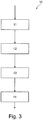
- FIG. 3 shows in a diagram 10 an exemplary process sequence of a method according to the invention for the production of connected heat exchanger elements.
- a thin adhesive layer is applied in block 11 on at least one first heat exchanger element and / or on a second heat exchanger element.
- the two heat exchanger elements are placed on each other in block 12 or merged to bond the heat transfer elements.
- the adhesive layer is about 10 .mu.m to 500 .mu.m, preferably 10 .mu.m to 100 .mu.m thick.
- the joining of the heat transfer elements at a temperature of about 100 ° C to 200 ° C, in particular 120 ° C to 180 ° C, take place.
- the heating preferably takes place over a predefined period of time.
- the heat transfer elements to be connected may alternatively be heated after assembly to a temperature of 100 ° C to 200 ° C, in particular 120 ° C to 180 ° C, for a predetermined period of time.
- the predefinable time duration is about 10 minutes or less, in particular 5 minutes or less.
- a pressure in the range of about 0.1 N / mm 2 to 0.7 N / mm 2 are applied to the heat transfer elements to be connected.
- a heat exchanger can be produced with such associated heat exchanger elements.
- the heat exchanger may be an evaporator, coolant radiator, radiator, condenser, intercooler, chiller, oil cooler, radiator, PTC heater, etc.
- the bond can be used for rib-tube bonding, activated carbon bonding or disk or plate bonding for flow channeling.
Landscapes
- Engineering & Computer Science (AREA)
- Manufacturing & Machinery (AREA)
- Chemical & Material Sciences (AREA)
- Chemical Kinetics & Catalysis (AREA)
- Electrochemistry (AREA)
- General Chemical & Material Sciences (AREA)
- Physics & Mathematics (AREA)
- Geometry (AREA)
- Thermal Sciences (AREA)
- Mechanical Engineering (AREA)
- General Engineering & Computer Science (AREA)
- Heat-Exchange Devices With Radiators And Conduit Assemblies (AREA)
Priority Applications (1)
| Application Number | Priority Date | Filing Date | Title |
|---|---|---|---|
| PL14710573T PL2976220T3 (pl) | 2013-03-18 | 2014-03-17 | Sposób wytwarzania połączonych elementów wymiennika ciepła |
Applications Claiming Priority (3)
| Application Number | Priority Date | Filing Date | Title |
|---|---|---|---|
| DE202013101450 | 2013-03-18 | ||
| DE201310206056 DE102013206056A1 (de) | 2013-03-18 | 2013-04-05 | Verfahren zur Herstellung von verbundenen Wärmeübertragerelementen |
| PCT/EP2014/055332 WO2014147035A1 (de) | 2013-03-18 | 2014-03-17 | Verfahren zur herstellung von verbundenen wärmeübertragerelementen |
Publications (2)
| Publication Number | Publication Date |
|---|---|
| EP2976220A1 EP2976220A1 (de) | 2016-01-27 |
| EP2976220B1 true EP2976220B1 (de) | 2019-05-08 |
Family
ID=51418867
Family Applications (1)
| Application Number | Title | Priority Date | Filing Date |
|---|---|---|---|
| EP14710573.8A Active EP2976220B1 (de) | 2013-03-18 | 2014-03-17 | Verfahren zur herstellung von verbundenen wärmeübertragerelementen |
Country Status (4)
| Country | Link |
|---|---|
| EP (1) | EP2976220B1 (pl) |
| DE (2) | DE102013206056A1 (pl) |
| PL (1) | PL2976220T3 (pl) |
| WO (1) | WO2014147035A1 (pl) |
Families Citing this family (5)
| Publication number | Priority date | Publication date | Assignee | Title |
|---|---|---|---|---|
| DE102015215053A1 (de) * | 2015-08-06 | 2017-02-09 | Mahle International Gmbh | Wärmeübertrager |
| DE102015217470A1 (de) * | 2015-09-11 | 2017-03-16 | Mahle International Gmbh | Verfahren zum Herstellen eines Wärmeübertragers |
| DE102016216114A1 (de) | 2016-08-26 | 2018-03-01 | Mahle International Gmbh | Wärmeübertrager mit einem Wärmeübertragerblock |
| DE102018208977A1 (de) | 2018-06-07 | 2019-12-12 | Mahle International Gmbh | Anordnung mit einer Leistungselektronik und einem Kühler |
| KR102020961B1 (ko) * | 2018-10-08 | 2019-09-11 | 삼익기전 주식회사 | 향상된 밀폐성능과 방열효율이 확보된 전자기기 방열장치용 열교환 조립체 |
Citations (1)
| Publication number | Priority date | Publication date | Assignee | Title |
|---|---|---|---|---|
| JP2007136292A (ja) * | 2005-11-15 | 2007-06-07 | National Institute Of Advanced Industrial & Technology | マイクロチャネル構造体の製造方法、マイクロチャネル構造体、およびマイクロリアクタ |
Family Cites Families (7)
| Publication number | Priority date | Publication date | Assignee | Title |
|---|---|---|---|---|
| US5058665A (en) * | 1989-03-28 | 1991-10-22 | Aisin Seiki Kabushiki Kaisha | Stacked-plate type heat exchanger |
| JP2002243395A (ja) * | 2001-02-15 | 2002-08-28 | Sanden Corp | 熱交換器およびその製造方法 |
| EP1376041B1 (de) * | 2002-06-21 | 2013-09-11 | Behr GmbH & Co. KG | Verfahren zur Herstellung eines Schichtwärmeübertragers |
| DE10228697C5 (de) * | 2002-06-27 | 2007-05-16 | Gea Energietechnik Gmbh | Wärmeübertrager |
| DE102005048452A1 (de) * | 2004-10-11 | 2006-04-20 | Behr Gmbh & Co. Kg | Wärmeübertrager |
| DE102008019556A1 (de) * | 2008-04-18 | 2009-10-22 | Esk Ceramics Gmbh & Co. Kg | Bauteil aus einem Stapel stoffschlüssig gefügter Platten und Verfahren zu dessen Herstellung |
| DE102011079586A1 (de) * | 2011-07-21 | 2013-01-24 | Behr Gmbh & Co. Kg | Modul für eine Wärmepumpe |
-
2013
- 2013-04-05 DE DE201310206056 patent/DE102013206056A1/de not_active Withdrawn
-
2014
- 2014-03-17 DE DE112014001511.3T patent/DE112014001511A5/de not_active Ceased
- 2014-03-17 PL PL14710573T patent/PL2976220T3/pl unknown
- 2014-03-17 WO PCT/EP2014/055332 patent/WO2014147035A1/de not_active Ceased
- 2014-03-17 EP EP14710573.8A patent/EP2976220B1/de active Active
Patent Citations (1)
| Publication number | Priority date | Publication date | Assignee | Title |
|---|---|---|---|---|
| JP2007136292A (ja) * | 2005-11-15 | 2007-06-07 | National Institute Of Advanced Industrial & Technology | マイクロチャネル構造体の製造方法、マイクロチャネル構造体、およびマイクロリアクタ |
Also Published As
| Publication number | Publication date |
|---|---|
| DE112014001511A5 (de) | 2016-04-14 |
| DE102013206056A1 (de) | 2014-09-18 |
| EP2976220A1 (de) | 2016-01-27 |
| WO2014147035A1 (de) | 2014-09-25 |
| PL2976220T3 (pl) | 2019-10-31 |
Similar Documents
| Publication | Publication Date | Title |
|---|---|---|
| EP2976220B1 (de) | Verfahren zur herstellung von verbundenen wärmeübertragerelementen | |
| DE3323622A1 (de) | Waermetauscher und verfahren zu seiner herstellung | |
| WO2014147033A1 (de) | Schichtwärmeübertragungseinrichtung und verfahren zur herstellung einer schichtwärmeübertragungseinrichtung | |
| EP0162192B1 (de) | Verfahren zum kohärenten Verbinden von Bauteilen mit einem deformierbaren Hilfsmaterial, insbesondere zum Verbinden dünnwandiger Bauteile | |
| DE102013204744A1 (de) | Schichtwärmeübertragungseinrichtung und Verfahren zur Herstellung einer Schichtwärmeübertragungseinrichtung | |
| DE102012012711A1 (de) | Verfahren zur Herstellung eines Niederdruck- Dünnwandwärmetauschers und Dünnwandwärmetauscher | |
| EP3121520B1 (de) | Wärmetauscher | |
| WO2017021152A1 (de) | Verfahren zum herstellen eines stapelscheibenkühlers und stapelscheibenkühler | |
| EP3194878A1 (de) | Verfahren zur herstellung eines wärmeübertragers | |
| EP2508833A2 (de) | Verdampferplatte für eine Kältemaschine | |
| EP2116793A2 (de) | Absorber, insbesondere für einen Sonnenkollektor und Verfahren zur Herstellung eines Absorbers für einen Sonnenkollektor | |
| DE102006056489A1 (de) | Verfahren zur Herstellung eines Stahl-/Aluminium-Verbundbauteils | |
| EP2058077B1 (de) | Verfahren zum Verbinden einer Aluminiumrippe mit einem Stahlrohr und Wärmetauscher mit einer derart hergestellten Einheit | |
| EP3121548B1 (de) | Wärmeaustauschelement | |
| DE102007008341A1 (de) | Wärmeübertrager | |
| WO2017021503A1 (de) | Verfahren zum herstellen eines wärmeübertragers und wärmeübertrager | |
| EP3686952A1 (de) | Gehäuseteil für einen batterieträger und verfahren zu dessen herstellung | |
| WO2006018246A1 (de) | Befestigen einer kühlschlange an der platine eines kühlgerätes | |
| DE4235908A1 (de) | Verfahren zum Verlöten eines Halbleiterkörpers mit einem Trägerelement | |
| WO2017021499A1 (de) | Verfahren zum herstellen eines wärmeübertragers und wärmeübertrager | |
| DE102024108742A1 (de) | Wellendichtring | |
| EP0981436B1 (de) | Flächenförmiger, kalt umformbarer materialverbund | |
| EP2957374B1 (de) | Verfahren zum elektrischen Verschweissen | |
| DE102023134992A1 (de) | Halbzeug für die Herstellung eines Wärmetauschers, Verfahren zur Herstellung eines solchen Halbzeugs, Verfahren zur Herstellung eines Wärmetauschers, Wärmetauscher und Fahrzeug mit demselben | |
| DE102018212294A1 (de) | Verfahren zum Herstellen eines Wärmeübertragers und Wärmeübertrager |
Legal Events
| Date | Code | Title | Description |
|---|---|---|---|
| PUAI | Public reference made under article 153(3) epc to a published international application that has entered the european phase |
Free format text: ORIGINAL CODE: 0009012 |
|
| 17P | Request for examination filed |
Effective date: 20151019 |
|
| AK | Designated contracting states |
Kind code of ref document: A1 Designated state(s): AL AT BE BG CH CY CZ DE DK EE ES FI FR GB GR HR HU IE IS IT LI LT LU LV MC MK MT NL NO PL PT RO RS SE SI SK SM TR |
|
| AX | Request for extension of the european patent |
Extension state: BA ME |
|
| DAX | Request for extension of the european patent (deleted) | ||
| REG | Reference to a national code |
Ref country code: DE Ref legal event code: R079 Ref document number: 502014011661 Country of ref document: DE Free format text: PREVIOUS MAIN CLASS: B32B0037120000 Ipc: F28F0001120000 |
|
| GRAP | Despatch of communication of intention to grant a patent |
Free format text: ORIGINAL CODE: EPIDOSNIGR1 |
|
| STAA | Information on the status of an ep patent application or granted ep patent |
Free format text: STATUS: GRANT OF PATENT IS INTENDED |
|
| RIC1 | Information provided on ipc code assigned before grant |
Ipc: H01M 10/6556 20140101ALI20181016BHEP Ipc: H01M 10/6554 20140101ALI20181016BHEP Ipc: F28F 1/12 20060101AFI20181016BHEP |
|
| INTG | Intention to grant announced |
Effective date: 20181120 |
|
| GRAJ | Information related to disapproval of communication of intention to grant by the applicant or resumption of examination proceedings by the epo deleted |
Free format text: ORIGINAL CODE: EPIDOSDIGR1 |
|
| STAA | Information on the status of an ep patent application or granted ep patent |
Free format text: STATUS: REQUEST FOR EXAMINATION WAS MADE |
|
| GRAR | Information related to intention to grant a patent recorded |
Free format text: ORIGINAL CODE: EPIDOSNIGR71 |
|
| GRAS | Grant fee paid |
Free format text: ORIGINAL CODE: EPIDOSNIGR3 |
|
| STAA | Information on the status of an ep patent application or granted ep patent |
Free format text: STATUS: GRANT OF PATENT IS INTENDED |
|
| INTC | Intention to grant announced (deleted) | ||
| GRAA | (expected) grant |
Free format text: ORIGINAL CODE: 0009210 |
|
| STAA | Information on the status of an ep patent application or granted ep patent |
Free format text: STATUS: THE PATENT HAS BEEN GRANTED |
|
| INTG | Intention to grant announced |
Effective date: 20190314 |
|
| AK | Designated contracting states |
Kind code of ref document: B1 Designated state(s): AL AT BE BG CH CY CZ DE DK EE ES FI FR GB GR HR HU IE IS IT LI LT LU LV MC MK MT NL NO PL PT RO RS SE SI SK SM TR |
|
| REG | Reference to a national code |
Ref country code: GB Ref legal event code: FG4D Free format text: NOT ENGLISH |
|
| REG | Reference to a national code |
Ref country code: CH Ref legal event code: EP Ref country code: AT Ref legal event code: REF Ref document number: 1130828 Country of ref document: AT Kind code of ref document: T Effective date: 20190515 |
|
| REG | Reference to a national code |
Ref country code: DE Ref legal event code: R096 Ref document number: 502014011661 Country of ref document: DE |
|
| REG | Reference to a national code |
Ref country code: IE Ref legal event code: FG4D Free format text: LANGUAGE OF EP DOCUMENT: GERMAN |
|
| REG | Reference to a national code |
Ref country code: NL Ref legal event code: MP Effective date: 20190508 |
|
| REG | Reference to a national code |
Ref country code: LT Ref legal event code: MG4D |
|
| PG25 | Lapsed in a contracting state [announced via postgrant information from national office to epo] |
Ref country code: PT Free format text: LAPSE BECAUSE OF FAILURE TO SUBMIT A TRANSLATION OF THE DESCRIPTION OR TO PAY THE FEE WITHIN THE PRESCRIBED TIME-LIMIT Effective date: 20190908 Ref country code: ES Free format text: LAPSE BECAUSE OF FAILURE TO SUBMIT A TRANSLATION OF THE DESCRIPTION OR TO PAY THE FEE WITHIN THE PRESCRIBED TIME-LIMIT Effective date: 20190508 Ref country code: AL Free format text: LAPSE BECAUSE OF FAILURE TO SUBMIT A TRANSLATION OF THE DESCRIPTION OR TO PAY THE FEE WITHIN THE PRESCRIBED TIME-LIMIT Effective date: 20190508 Ref country code: NL Free format text: LAPSE BECAUSE OF FAILURE TO SUBMIT A TRANSLATION OF THE DESCRIPTION OR TO PAY THE FEE WITHIN THE PRESCRIBED TIME-LIMIT Effective date: 20190508 Ref country code: FI Free format text: LAPSE BECAUSE OF FAILURE TO SUBMIT A TRANSLATION OF THE DESCRIPTION OR TO PAY THE FEE WITHIN THE PRESCRIBED TIME-LIMIT Effective date: 20190508 Ref country code: NO Free format text: LAPSE BECAUSE OF FAILURE TO SUBMIT A TRANSLATION OF THE DESCRIPTION OR TO PAY THE FEE WITHIN THE PRESCRIBED TIME-LIMIT Effective date: 20190808 Ref country code: LT Free format text: LAPSE BECAUSE OF FAILURE TO SUBMIT A TRANSLATION OF THE DESCRIPTION OR TO PAY THE FEE WITHIN THE PRESCRIBED TIME-LIMIT Effective date: 20190508 Ref country code: SE Free format text: LAPSE BECAUSE OF FAILURE TO SUBMIT A TRANSLATION OF THE DESCRIPTION OR TO PAY THE FEE WITHIN THE PRESCRIBED TIME-LIMIT Effective date: 20190508 Ref country code: HR Free format text: LAPSE BECAUSE OF FAILURE TO SUBMIT A TRANSLATION OF THE DESCRIPTION OR TO PAY THE FEE WITHIN THE PRESCRIBED TIME-LIMIT Effective date: 20190508 |
|
| PG25 | Lapsed in a contracting state [announced via postgrant information from national office to epo] |
Ref country code: RS Free format text: LAPSE BECAUSE OF FAILURE TO SUBMIT A TRANSLATION OF THE DESCRIPTION OR TO PAY THE FEE WITHIN THE PRESCRIBED TIME-LIMIT Effective date: 20190508 Ref country code: LV Free format text: LAPSE BECAUSE OF FAILURE TO SUBMIT A TRANSLATION OF THE DESCRIPTION OR TO PAY THE FEE WITHIN THE PRESCRIBED TIME-LIMIT Effective date: 20190508 Ref country code: GR Free format text: LAPSE BECAUSE OF FAILURE TO SUBMIT A TRANSLATION OF THE DESCRIPTION OR TO PAY THE FEE WITHIN THE PRESCRIBED TIME-LIMIT Effective date: 20190809 Ref country code: BG Free format text: LAPSE BECAUSE OF FAILURE TO SUBMIT A TRANSLATION OF THE DESCRIPTION OR TO PAY THE FEE WITHIN THE PRESCRIBED TIME-LIMIT Effective date: 20190808 |
|
| PG25 | Lapsed in a contracting state [announced via postgrant information from national office to epo] |
Ref country code: DK Free format text: LAPSE BECAUSE OF FAILURE TO SUBMIT A TRANSLATION OF THE DESCRIPTION OR TO PAY THE FEE WITHIN THE PRESCRIBED TIME-LIMIT Effective date: 20190508 Ref country code: EE Free format text: LAPSE BECAUSE OF FAILURE TO SUBMIT A TRANSLATION OF THE DESCRIPTION OR TO PAY THE FEE WITHIN THE PRESCRIBED TIME-LIMIT Effective date: 20190508 Ref country code: CZ Free format text: LAPSE BECAUSE OF FAILURE TO SUBMIT A TRANSLATION OF THE DESCRIPTION OR TO PAY THE FEE WITHIN THE PRESCRIBED TIME-LIMIT Effective date: 20190508 Ref country code: RO Free format text: LAPSE BECAUSE OF FAILURE TO SUBMIT A TRANSLATION OF THE DESCRIPTION OR TO PAY THE FEE WITHIN THE PRESCRIBED TIME-LIMIT Effective date: 20190508 Ref country code: SK Free format text: LAPSE BECAUSE OF FAILURE TO SUBMIT A TRANSLATION OF THE DESCRIPTION OR TO PAY THE FEE WITHIN THE PRESCRIBED TIME-LIMIT Effective date: 20190508 |
|
| REG | Reference to a national code |
Ref country code: DE Ref legal event code: R097 Ref document number: 502014011661 Country of ref document: DE |
|
| PG25 | Lapsed in a contracting state [announced via postgrant information from national office to epo] |
Ref country code: IT Free format text: LAPSE BECAUSE OF FAILURE TO SUBMIT A TRANSLATION OF THE DESCRIPTION OR TO PAY THE FEE WITHIN THE PRESCRIBED TIME-LIMIT Effective date: 20190508 Ref country code: SM Free format text: LAPSE BECAUSE OF FAILURE TO SUBMIT A TRANSLATION OF THE DESCRIPTION OR TO PAY THE FEE WITHIN THE PRESCRIBED TIME-LIMIT Effective date: 20190508 |
|
| PLBE | No opposition filed within time limit |
Free format text: ORIGINAL CODE: 0009261 |
|
| STAA | Information on the status of an ep patent application or granted ep patent |
Free format text: STATUS: NO OPPOSITION FILED WITHIN TIME LIMIT |
|
| PG25 | Lapsed in a contracting state [announced via postgrant information from national office to epo] |
Ref country code: TR Free format text: LAPSE BECAUSE OF FAILURE TO SUBMIT A TRANSLATION OF THE DESCRIPTION OR TO PAY THE FEE WITHIN THE PRESCRIBED TIME-LIMIT Effective date: 20190508 |
|
| 26N | No opposition filed |
Effective date: 20200211 |
|
| PGFP | Annual fee paid to national office [announced via postgrant information from national office to epo] |
Ref country code: PL Payment date: 20200218 Year of fee payment: 7 |
|
| PG25 | Lapsed in a contracting state [announced via postgrant information from national office to epo] |
Ref country code: SI Free format text: LAPSE BECAUSE OF FAILURE TO SUBMIT A TRANSLATION OF THE DESCRIPTION OR TO PAY THE FEE WITHIN THE PRESCRIBED TIME-LIMIT Effective date: 20190508 |
|
| PG25 | Lapsed in a contracting state [announced via postgrant information from national office to epo] |
Ref country code: MC Free format text: LAPSE BECAUSE OF FAILURE TO SUBMIT A TRANSLATION OF THE DESCRIPTION OR TO PAY THE FEE WITHIN THE PRESCRIBED TIME-LIMIT Effective date: 20190508 |
|
| REG | Reference to a national code |
Ref country code: CH Ref legal event code: PL |
|
| REG | Reference to a national code |
Ref country code: BE Ref legal event code: MM Effective date: 20200331 |
|
| PG25 | Lapsed in a contracting state [announced via postgrant information from national office to epo] |
Ref country code: LU Free format text: LAPSE BECAUSE OF NON-PAYMENT OF DUE FEES Effective date: 20200317 |
|
| PG25 | Lapsed in a contracting state [announced via postgrant information from national office to epo] |
Ref country code: CH Free format text: LAPSE BECAUSE OF NON-PAYMENT OF DUE FEES Effective date: 20200331 Ref country code: LI Free format text: LAPSE BECAUSE OF NON-PAYMENT OF DUE FEES Effective date: 20200331 Ref country code: IE Free format text: LAPSE BECAUSE OF NON-PAYMENT OF DUE FEES Effective date: 20200317 Ref country code: FR Free format text: LAPSE BECAUSE OF NON-PAYMENT OF DUE FEES Effective date: 20200331 |
|
| PG25 | Lapsed in a contracting state [announced via postgrant information from national office to epo] |
Ref country code: BE Free format text: LAPSE BECAUSE OF NON-PAYMENT OF DUE FEES Effective date: 20200331 |
|
| GBPC | Gb: european patent ceased through non-payment of renewal fee |
Effective date: 20200317 |
|
| PG25 | Lapsed in a contracting state [announced via postgrant information from national office to epo] |
Ref country code: GB Free format text: LAPSE BECAUSE OF NON-PAYMENT OF DUE FEES Effective date: 20200317 |
|
| REG | Reference to a national code |
Ref country code: AT Ref legal event code: MM01 Ref document number: 1130828 Country of ref document: AT Kind code of ref document: T Effective date: 20200317 |
|
| PG25 | Lapsed in a contracting state [announced via postgrant information from national office to epo] |
Ref country code: AT Free format text: LAPSE BECAUSE OF NON-PAYMENT OF DUE FEES Effective date: 20200317 |
|
| PG25 | Lapsed in a contracting state [announced via postgrant information from national office to epo] |
Ref country code: MT Free format text: LAPSE BECAUSE OF FAILURE TO SUBMIT A TRANSLATION OF THE DESCRIPTION OR TO PAY THE FEE WITHIN THE PRESCRIBED TIME-LIMIT Effective date: 20190508 Ref country code: CY Free format text: LAPSE BECAUSE OF FAILURE TO SUBMIT A TRANSLATION OF THE DESCRIPTION OR TO PAY THE FEE WITHIN THE PRESCRIBED TIME-LIMIT Effective date: 20190508 |
|
| PG25 | Lapsed in a contracting state [announced via postgrant information from national office to epo] |
Ref country code: MK Free format text: LAPSE BECAUSE OF FAILURE TO SUBMIT A TRANSLATION OF THE DESCRIPTION OR TO PAY THE FEE WITHIN THE PRESCRIBED TIME-LIMIT Effective date: 20190508 Ref country code: IS Free format text: LAPSE BECAUSE OF FAILURE TO SUBMIT A TRANSLATION OF THE DESCRIPTION OR TO PAY THE FEE WITHIN THE PRESCRIBED TIME-LIMIT Effective date: 20190908 |
|
| PG25 | Lapsed in a contracting state [announced via postgrant information from national office to epo] |
Ref country code: PL Free format text: LAPSE BECAUSE OF NON-PAYMENT OF DUE FEES Effective date: 20210317 |
|
| P01 | Opt-out of the competence of the unified patent court (upc) registered |
Effective date: 20240527 |
|
| PGFP | Annual fee paid to national office [announced via postgrant information from national office to epo] |
Ref country code: DE Payment date: 20260319 Year of fee payment: 13 |