EP2975731A2 - Disc rotor for an electric machine - Google Patents
Disc rotor for an electric machine Download PDFInfo
- Publication number
- EP2975731A2 EP2975731A2 EP15167077.5A EP15167077A EP2975731A2 EP 2975731 A2 EP2975731 A2 EP 2975731A2 EP 15167077 A EP15167077 A EP 15167077A EP 2975731 A2 EP2975731 A2 EP 2975731A2
- Authority
- EP
- European Patent Office
- Prior art keywords
- permanent magnets
- support member
- pancake
- rotor
- rotor body
- Prior art date
- Legal status (The legal status is an assumption and is not a legal conclusion. Google has not performed a legal analysis and makes no representation as to the accuracy of the status listed.)
- Granted
Links
- 239000000463 material Substances 0.000 claims abstract description 34
- 235000012771 pancakes Nutrition 0.000 claims abstract description 25
- 239000012811 non-conductive material Substances 0.000 claims abstract description 7
- 230000002093 peripheral effect Effects 0.000 claims description 4
- 230000008878 coupling Effects 0.000 claims description 3
- 238000010168 coupling process Methods 0.000 claims description 3
- 238000005859 coupling reaction Methods 0.000 claims description 3
- 230000017525 heat dissipation Effects 0.000 description 9
- 239000004020 conductor Substances 0.000 description 6
- 229920003023 plastic Polymers 0.000 description 5
- 239000004033 plastic Substances 0.000 description 5
- 229910052782 aluminium Inorganic materials 0.000 description 3
- XAGFODPZIPBFFR-UHFFFAOYSA-N aluminium Chemical compound [Al] XAGFODPZIPBFFR-UHFFFAOYSA-N 0.000 description 3
- 230000001419 dependent effect Effects 0.000 description 3
- 230000020169 heat generation Effects 0.000 description 3
- XEEYBQQBJWHFJM-UHFFFAOYSA-N Iron Chemical compound [Fe] XEEYBQQBJWHFJM-UHFFFAOYSA-N 0.000 description 2
- 230000006378 damage Effects 0.000 description 2
- 230000003247 decreasing effect Effects 0.000 description 2
- 230000005347 demagnetization Effects 0.000 description 2
- 238000010438 heat treatment Methods 0.000 description 2
- 238000003475 lamination Methods 0.000 description 2
- 239000000696 magnetic material Substances 0.000 description 2
- BGPVFRJUHWVFKM-UHFFFAOYSA-N N1=C2C=CC=CC2=[N+]([O-])C1(CC1)CCC21N=C1C=CC=CC1=[N+]2[O-] Chemical compound N1=C2C=CC=CC2=[N+]([O-])C1(CC1)CCC21N=C1C=CC=CC1=[N+]2[O-] BGPVFRJUHWVFKM-UHFFFAOYSA-N 0.000 description 1
- 239000000853 adhesive Substances 0.000 description 1
- 238000004026 adhesive bonding Methods 0.000 description 1
- 230000001070 adhesive effect Effects 0.000 description 1
- 230000002411 adverse Effects 0.000 description 1
- 238000004873 anchoring Methods 0.000 description 1
- 150000001875 compounds Chemical class 0.000 description 1
- 238000010276 construction Methods 0.000 description 1
- 230000007423 decrease Effects 0.000 description 1
- 230000004907 flux Effects 0.000 description 1
- 239000004519 grease Substances 0.000 description 1
- 229910052742 iron Inorganic materials 0.000 description 1
- 229910052751 metal Inorganic materials 0.000 description 1
- 239000002184 metal Substances 0.000 description 1
- 229910001172 neodymium magnet Inorganic materials 0.000 description 1
- 238000010792 warming Methods 0.000 description 1
- 238000004804 winding Methods 0.000 description 1
Images


Classifications
-
- H—ELECTRICITY
- H02—GENERATION; CONVERSION OR DISTRIBUTION OF ELECTRIC POWER
- H02K—DYNAMO-ELECTRIC MACHINES
- H02K1/00—Details of the magnetic circuit
- H02K1/06—Details of the magnetic circuit characterised by the shape, form or construction
- H02K1/22—Rotating parts of the magnetic circuit
- H02K1/27—Rotor cores with permanent magnets
- H02K1/2793—Rotors axially facing stators
- H02K1/2795—Rotors axially facing stators the rotor consisting of two or more circumferentially positioned magnets
- H02K1/2796—Rotors axially facing stators the rotor consisting of two or more circumferentially positioned magnets where both axial sides of the rotor face a stator
-
- H—ELECTRICITY
- H02—GENERATION; CONVERSION OR DISTRIBUTION OF ELECTRIC POWER
- H02K—DYNAMO-ELECTRIC MACHINES
- H02K9/00—Arrangements for cooling or ventilating
- H02K9/22—Arrangements for cooling or ventilating by solid heat conducting material embedded in, or arranged in contact with, the stator or rotor, e.g. heat bridges
- H02K9/223—Heat bridges
-
- H—ELECTRICITY
- H02—GENERATION; CONVERSION OR DISTRIBUTION OF ELECTRIC POWER
- H02K—DYNAMO-ELECTRIC MACHINES
- H02K21/00—Synchronous motors having permanent magnets; Synchronous generators having permanent magnets
- H02K21/12—Synchronous motors having permanent magnets; Synchronous generators having permanent magnets with stationary armatures and rotating magnets
- H02K21/24—Synchronous motors having permanent magnets; Synchronous generators having permanent magnets with stationary armatures and rotating magnets with magnets axially facing the armatures, e.g. hub-type cycle dynamos
Landscapes
- Engineering & Computer Science (AREA)
- Power Engineering (AREA)
- Permanent Field Magnets Of Synchronous Machinery (AREA)
- Iron Core Of Rotating Electric Machines (AREA)
Abstract
Die Erfindung betrifft einen Scheibenläufer (2, 6, 7) für eine elektrische Maschine (1), umfassend: - einen kreis- oder ringförmigen scheibenartigen Läuferkörper (21, 61, 71); - Permanentmagnete (23, 62, 73), die in Umfangsrichtung zueinander benachbart an dem Läuferkörper (21, 61, 71) angeordnet sind; wobei der Läuferkörper (21, 61, 71) ein erstes Material zur Ableitung von Wärme in radialer Richtung und im Bereich der Permanentmagnete ein zweites elektrisch nicht leitendes Material aufweist.The invention relates to a pancake (2, 6, 7) for an electric machine (1), comprising: - A circular or annular disc-like rotor body (21, 61, 71); - permanent magnets (23, 62, 73) circumferentially adjacent to each other on the rotor body (21, 61, 71) are arranged; wherein the rotor body (21, 61, 71) comprises a first material for dissipating heat in the radial direction and in the region of the permanent magnets has a second electrically non-conductive material.
Description
Die Erfindung betrifft elektrische Maschinen mit Scheibenläufern, insbesondere Axialfluss- oder Transversalflussmaschinen. Weiterhin betrifft die vorliegende Erfindung den Aufbau von Scheibenläufern für die Reduzierung einer Wärmeentwicklung und zur Verbesserung der Wärmeabfuhr.The invention relates to electrical machines with disc rotors, in particular axial flow or transverse flux machines. Furthermore, the present invention relates to the construction of disc rotors for the reduction of heat generation and to improve the heat dissipation.
Elektrische Maschinen, insbesondere permanentmagneterregte elektrische Maschinen mit Scheibenläufern, sind aus dem Stand der Technik bekannt. So zeigt beispielsweise die Druckschrift
Bei permanentmagneterregten elektrischen Maschinen können in elektrisch leitfähigen Materialien während des Betriebs Wirbelströme induziert werden, die eine Erwärmung hervorrufen. Bei Scheibenläufern, bei denen die Permanentmagnete in elektrisch leitenden Materialien, wie zum Beispiel einen durch Blechlamellen (Eisenblech) aufgebauten Läuferkörper, eingesetzt sind, findet daher eine Erwärmung im Betrieb statt.In permanent magnet-excited electrical machines eddy currents can be induced in electrically conductive materials during operation, causing a warming. In disc rotors, in which the permanent magnets in electrically conductive materials, such as a built-up by laminations (sheet iron) rotor body, are used, therefore, a heating takes place during operation.
Je nach Auslegung können Permanentmagnete einen Anteil an Seltenen Erden aufweisen, wie beispielsweise NdFeB-Magnete. Die Remanenz derartiger Permanentmagnete ist stark temperaturabhängig ist und nimmt mit steigender Temperatur ab. Derartige Permanentmagnete weisen auch eine temperaturabhängige Koerzitivfeldstärke auf, die ebenfalls bei einer Erhöhung der Temperatur abnimmt. Führt die abnehmende Koerzitivfeldstärke im Betrieb zu einer Umkehr der Magnetfeldrichtung durch den Permanentmagneten, kann es zu einer Entmagnetisierung und damit zur Beschädigung oder Zerstörung der elektrischen Maschinen kommen.Depending on the design, permanent magnets may have a proportion of rare earths, such as NdFeB magnets. The remanence of such permanent magnets is strongly temperature-dependent and increases with increasing temperature from. Such permanent magnets also have a temperature-dependent coercive force, which also decreases with an increase in temperature. If the decreasing coercive field strength during operation leads to a reversal of the magnetic field direction by the permanent magnet, this can lead to demagnetization and thus damage or destruction of the electrical machines.
Insbesondere wenn elektrische Maschinen in Arbeitsbereichen mit hoher Umgebungstemperatur eingesetzt werden, ist der Spielraum für eine weitere Temperaturerhöhung aufgrund der durch die Wirbelströme bewirkten Wärmeentwicklung begrenzt. Daher müssen für solche elektrischen Maschinen Permanentmagnete mit hoher Koerzitivfeldstärke eingesetzt werden. Diese Permanentmagnete sind jedoch teuer, und es wird daher als Material für den Läuferkörper des Scheibenläufers häufig ein elektrisch nicht leitfähiges Material eingesetzt. Jedoch haben insbesondere Kunststoffe als elektrisch nichtleitende Materialien für den Läuferkörper den Nachteil, dass in den Permanentmagneten entstehende Wärme schlecht abgeführt werden kann und dadurch eine übermäßige Erwärmung der Permanentmagnete auftritt mit den zuvor genannten Nachteilen hinsichtlich der abnehmenden Remanenz und Koerzitivfeldstärke.In particular, when electric machines are used in work areas with high ambient temperature, the scope for a further increase in temperature due to the heat generated by the eddy currents is limited. Therefore, permanent magnets with high coercive force must be used for such electrical machines. However, these permanent magnets are expensive, and it is therefore often used as a material for the rotor body of the disc rotor, an electrically non-conductive material. However, in particular plastics as electrically non-conductive materials for the rotor body have the disadvantage that heat generated in the permanent magnets can be dissipated poorly and thereby excessive heating of the permanent magnets occurs with the aforementioned disadvantages in terms of decreasing remanence and coercive force.
Es ist daher Aufgabe der vorliegenden Erfindung, einen Scheibenläufer für eine elektrische Maschine zur Verfügung zu stellen, der eine reduzierte Wärmeentwicklung im Betrieb aufweist und bei dem die Wärme in verbesserter Weise über eine Läuferwelle abgeführt werden kann.It is therefore an object of the present invention to provide a pancake for an electric machine, which has a reduced heat generation during operation and in which the heat can be dissipated in an improved manner via a rotor shaft.
Diese Aufgabe wird durch den Scheibenläufer für eine elektrische Maschine gemäß Anspruch 1 sowie durch die elektrische Maschine gemäß dem nebengeordneten Anspruch gelöst.This object is achieved by the disc rotor for an electric machine according to claim 1 and by the electric machine according to the independent claim.
Weitere Ausgestaltungen sind in den abhängigen Ansprüchen angegeben.Further embodiments are specified in the dependent claims.
Gemäß einem ersten Aspekt ist ein Scheibenläufer für eine elektrische Maschine vorgesehen, umfassend:
- einen insbesondere kreis- oder ringförmigen scheibenartigen Läuferkörper; und
- Permanentmagnete, die als ein Ring in Umfangsrichtung zueinander benachbart an dem Läuferkörper angeordnet sind;
- a particular circular or annular disk-like rotor body; and
- Permanent magnets arranged as a ring circumferentially adjacent to each other on the rotor body;
Eine Idee des obigen Scheibenläufers besteht darin, den Scheibenläufer abgesehen von den Permanentmagneten unter Verwendung von mehreren Materialien aufzubauen. Dabei wird ein elektrisch nichtleitendes zweites Material im Bereich der Permanentmagnete verwendet und ein thermisch leitfähiges erstes Material zwischen den Permanentmagneten und der Läuferwelle angeordnet. Dadurch ist zum einen eine gute und gleichmäßige Wärmeabführung von den Permanentmagneten zur Läuferwelle gewährleistet, und zum anderen wird die Wärmeentstehung aufgrund von induzierten Wirbelströmen im Bereich der Permanentmagneten unterbunden bzw. reduziert, ohne die mechanische Stabilität des Scheibenläufers zu beeinträchtigen.One idea of the above disc rotor is to construct the pancake other than the permanent magnets using multiple materials. In this case, an electrically nonconductive second material is used in the region of the permanent magnets and a thermally conductive first material is arranged between the permanent magnet and the rotor shaft. On the one hand, this ensures a good and uniform heat dissipation from the permanent magnets to the rotor shaft, and, on the other hand, the generation of heat due to induced eddy currents in the region of the permanent magnets is prevented or reduced, without adversely affecting the mechanical stability of the disc rotor.
Weiterhin ist es dadurch möglich, kostengünstigere Permanentmagnete zu verwenden, da im Betrieb der elektrischen Maschine geringere Temperaturen zu erwarten sind als dies bei Scheibenläufern, deren Läuferkörper vollständig aus elektrisch leitenden Materialien aufgebaut sind, zu erwarten wäre. Trotzdem wird aufgrund des verendeten ersten Materials eine gute Wärmeabelitung hin zur Läuferwelle bzw. Läufrnabe gewährleistet. Ferner wird eine bessere Entmagnetisierungsfestigkeit der Permanentmagnete in dem Scheibenläufer erreicht.Furthermore, this makes it possible to use more cost-effective permanent magnets, since during operation of the electric machine lower temperatures are to be expected than would be expected with disc rotors whose rotor bodies are constructed completely from electrically conductive materials. Nevertheless, a good Wärmeabelitung towards the rotor shaft or Läufrnabe guaranteed due to the first material died. Furthermore, a better demagnetization resistance of the permanent magnets in the pancake is achieved.
Weiterhin kann das erste Material eine höhere thermische Leitfähigkeit aufweisen als das zweite Material und/oder das erste Material eine höhere elektrische Leitfähigkeit aufweisen als das zweite Material.Furthermore, the first material may have a higher thermal conductivity than the second material and / or the first material may have a higher electrical conductivity than the second material.
Es kann vorgesehen sein, dass der Läuferkörper ein radial inneres Trägerelement mit dem ersten Material und einen das Trägerelement umgebenden Haltekäfig mit dem zweiten Material aufweist, wobei der Haltekäfig Ausnehmungen definiert, um die Permanentmagnete aufzunehmen.It can be provided that the rotor body has a radially inner support element with the first material and a support cage surrounding the support member with the second material, wherein the holding cage defines recesses to receive the permanent magnets.
Insbesondere können die Permanentmagnete an einem Außenumfang des Trägerelements anliegen, so dass Wärme in den Permanentmagneten nach radial innen über das Trägerelement ableitbar ist, und wobei die Permanentmagnete mit dem Trägerelement über ein thermisches Kopplungsmittel, wie z.B. eine Wärmeleitpaste, gekoppelt sind.In particular, the permanent magnets may abut an outer circumference of the support member so that heat in the permanent magnets may be dissipated radially inwardly over the support member, and wherein the permanent magnets are connected to the support member via a thermal coupling means, such as e.g. a thermal compound, are coupled.
Weiterhin kann der Haltekäfig mit dem Trägerelement formschlüssig verbunden sein.Furthermore, the holding cage can be positively connected to the carrier element.
Der Läuferkörper kann ein Trägerelement mit dem ersten Material aufweisen, das auf einer oder beiden Seiten Magnetaufnahmebereiche als in axiale Richtung gerichtete Ausnehmungen aufweist, um Permanentmagnete aufzunehmen, wobei eine Ummantelung mit dem zweiten Material vorgesehen ist, um die Permanentmagnete zumindest teilweise zu umgeben oder zu überdecken.The rotor body may include a support member having the first material having on one or both sides magnet receiving portions as axially directed recesses for receiving permanent magnets, wherein a sheathing with the second material is provided to at least partially surround or cover the permanent magnets ,
Insbesondere kann das Trägerelement einen umlaufenden in axialer Richtung nach einer oder beiden Seiten abstehenden Rand aufweisen, um die Permanentmagnete in den Magnetaufnahmebereichen zu halten.In particular, the support member may have a circumferential in the axial direction of one or both sides projecting edge to hold the permanent magnets in the magnetic receiving areas.
Es kann vorgesehen sein, dass der Läuferkörper ein Trägerelement mit dem ersten Material aufweist, das mit durchgängigen Ausnehmungen zur Aufnahme von in Umfangsrichtung zueinander benachbarten Permanentmagneten versehen ist, wobei eine Ummantelung mit dem zweiten Material vorgesehen ist, um die Permanentmagnete zumindest teilweise zu umgeben oder zu überdecken.It can be provided that the rotor body comprises a carrier element with the first material, which is provided with continuous recesses for receiving circumferentially adjacent permanent magnets, wherein a sheath with the second material is provided to at least partially surround the permanent magnets or to cover.
Gemäß einer Ausführungsform kann das Trägerelement in einem bezüglich der Ausnehmungen radial äußeren Bereich Segmente aufweisen, die sich in axialer Richtung insbesondere bezüglich der Umfangsrichtung wechselweise erstreckenAccording to one embodiment, the support element may have, in a region which is radially outer with respect to the recesses, segments which extend alternately in the axial direction, in particular with respect to the circumferential direction
Insbesondere kann das Trägerelement mehrlagig ausgebildet sein.In particular, the carrier element can be designed in multiple layers.
Das Trägerelement kann an einer radial äußeren Kante der Ausnehmungen mit einem sich in axialer Richtung erstreckenden Bereich versehen sein.The support member may be provided at a radially outer edge of the recesses with an axially extending portion.
Weiterhin kann das Trägerelement an mindestens einer Seite mit Strukturierungen versehen sein.Furthermore, the carrier element may be provided on at least one side with structuring.
Gemäß einem weiteren Aspekt ist eine elektrische Maschine mit dem obigen Scheibenläufer und einer Statoranordnung mit mindestens einer Statoreinheit vorgesehen, wobei der Scheibenläufer axial versetzt zu der Statoreinheit angeordnet ist.According to another aspect, there is provided an electric machine having the above pancake and a stator assembly having at least one stator unit, the pancake being axially offset from the stator unit.
Ausführungsformen werden nachfolgend anhand der beigefügten Zeichnungen näher erläutert. Es zeigen:
- Figur 1
- eine Querschnittsdarstellung durch eine elektrische Maschine mit einem Scheibenläufer;
- Figuren 2a und 2b
- eine Draufsichtdarstellung auf einen Scheibenläufer, der aus zwei Materialien aufgebaut ist, sowie eine Querschnittsdarstellung entlang der Schnittlinie S-S;
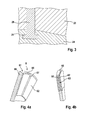
Figur 3- eine Darstellung eines Beispiels für eine formschlüssige Verbindung zwischen einem Trägerelement und einem Haltekäfig eines Scheibenläufers;
- Figuren 4a und 4b
- verschiedene Darstellungen eines weiteren Scheibenläufers mit einem Läuferkörper mit Ausnehmungen zur Aufnahme der Permanentmagnete;
- Figuren 5a und 5b
- verschiedene Darstellungen eines weiteren Scheibenläufers mit einem Läuferkörper mit Ausnehmungen zur Aufnahme der Permanentmagnete;
- Figuren 6a bis 6c
- Querschnittsansichten zur Darstellung von Möglichkeiten der Ausgestaltung des Läuferkörpers bei der Ausführungsform der
Figuren 5a und 5b ; und - Figur 7
- ein Draufsicht auf den Läuferkörper der
Figuren 5a und 5b , wobei mindenstens eine Seitenfläche mit einer Strukturierung versehen ist.
- FIG. 1
- a cross-sectional view through an electric machine with a pancake;
- FIGS. 2a and 2b
- a plan view of a pancake, which is constructed of two materials, and a cross-sectional view along the section line SS;
- FIG. 3
- a representation of an example of a positive connection between a support member and a holding cage of a disc rotor;
- FIGS. 4a and 4b
- various representations of another disc rotor with a rotor body with recesses for receiving the permanent magnets;
- FIGS. 5a and 5b
- various representations of another disc rotor with a rotor body with recesses for receiving the permanent magnets;
- FIGS. 6a to 6c
- Cross-sectional views illustrating ways of designing the rotor body in the embodiment of
FIGS. 5a and 5b ; and - FIG. 7
- a plan view of the rotor body of
FIGS. 5a and 5b , wherein at least one side surface is provided with a structuring.
Der Scheibenläufer 2 weist einen ringförmigen Läuferkörper 21 auf und ist drehbeweglich an einer Läuferwelle 4 gehalten. Der Läuferkörper 21 kann direkt mit der Läuferwelle 4 gekoppelt sein oder über ein z.B. topfförmiges Trägerelement 22 an einer axial versetzten Position mit der Läuferwelle 4 gekoppelt sein.The
Der Läuferkörper 21 des Scheibenläufers 2 kann zwischen zwei Statoreinheiten 31 der Statoranordnung 3 angeordnet sein. Jede der Statoreinheiten 31 kann jeweils in axialer Richtung A abstehende Statorzähne 32 aufweisen. Die Statorzähne 31 können weiterhin in Umfangsrichtung mit Abstand zueinander benachbart konzentrisch um die Drehachse der Läuferwelle 4 angeordnet sein. Die Statoreinheiten 31 können jeweils umlaufende Statorwicklungen (nicht gezeigt) umfassen, die zur wechselweisen Magnetisierung der Statorzähne 32 bestromt werden können.The
Der Scheibenläufer 2 kann in einem magnetisch aktiven Bereich mit Permanentmagneten 23 versehen sein, die in Umfangsrichtung nebeneinander angeordnet sind und die eine Polrichtung in Umfangsrichtung aufweisen können. Läuferpole werden dadurch zwischen den Permanentmagneten 23 des Scheibenläufers 2 ausgebildet. Alternativ kann die Polungsrichtung der Permanentmagnete 23 auch in axialer Richtung verlaufen.The
Die Permanentmagnete 4 werden durch einen Haltekäfig 25 des Läuferkörpers 21 gehalten, der Ausnehmungen 26 zur Aufnahme der Permanentmagnete 4 aufweist. Der Haltekäfig 25 weist radial außerhalb der Ausnehmungen 26 Brückenelemente 27 auf, die über die Permanentmagnete 23 verlaufen und diese in den Ausnehmungen 26 halten. Zwischen die Permanentmagnete 23 des Scheibenläufers 2 erstrecken sich Schenkel 28. Der Haltekäfig 25 ist mit abstehenden Enden der Schenkel 28 mit dem Trägerelement 24 verbunden.The
Zur Verbesserung der Wärmeabführung aus den Permanentmagneten 23 ist das Trägerelement 24 aus einem thermisch gut leitfähigen Material, insbesondere aus einem Metall ausgebildet. Das Trägerelement 24 kann beispielsweise aus Blechlamellen ausgebildet sein. Um einen magnetischen Kurzschluss durch das Trägerelement 24 zu vermeiden, kann es vorteilhaft sein, das Trägerelement 24 aus einem nichtmagnetischen Material, wie beispielsweise Aluminium oder dergleichen, auszubilden.To improve the heat dissipation from the
Der Haltekäfig 25, der mit den Brückenelementen 27 radial außerhalb und mit seinen Schenkel 28 zwischen den Permanentmagneten 23 angeordnet ist, ist vorzugsweise aus einem elektrisch nichtleitenden Material, wie beispielsweise einem Kunststoff, ausgebildet, so dass dort keine Wirbelströme induziert werden, die zu einer Wärmeentwicklung führen können.The holding
Zur Verbesserung der Wärmeabfuhr aus den Permanentmagneten 23 in Richtung des Trägerelements 24 kann an der Außenseite des Trägerelements 21, d.h. zwischen dem Trägerelement 24 und den Permanentmagneten 23, eine Wärmeleitpaste oder dergleichen als ein thermisches Kopplungsmittel vorgesehen werden.In order to improve the heat removal from the
In den
Im Bereich des Magnetaufnahmebereichs 63 weist das Trägerelement 66 eine verringerte Dicke auf, wobei die verbleibende Dicke des Trägerelements 66 vorzugsweise so gewählt ist, dass durch die Wärmeabführung aus dem Permanentmagneten 62 größer ist als die durch Wirbelströme im Betrieb der elektrischen Maschine darin erzeugte Wärme. Weiterhin ist sicherzustellen, dass die Dicke des Trägerelements 66 ausreichend ist, um die ausreichende Festigkeit auch beim Betrieb bei der maximalen Drehzahl zu gewährleisten.In the region of the magnetic receiving
Um beim Betrieb die Permanentmagneten 62 zuverlässig an dem Trägerelement 66 zu halten, kann das Trägerelement 66 mit einem umlaufenden Rand 65 vorgesehen sein, an dem sich die Permanentmagneten 62 nach außen hin abstützen können. Bei der gezeigten Ausführungsform sind die Permanentmagnete 62 beidseitig des Trägerelements 66 in entsprechenden Ausnehmungen des Magnetaufnahmebereichs 63 angeordnet, wobei zur Ausbildung von Läuferpolen die Polungsrichtungen in axialer Richtung oder in Umfangsrichtung ausgeführt sein können.In order to reliably hold the
Alternativ kann der Läuferkörper 61 auch ohne umlaufenden Rand 65 vorgesehen sein, um die Massenträgheit des Scheibenläufers 6 zu reduzieren. In diesem Fall ist eine zuverlässiges Halten der Permanentmagnete 62 durch Verkleben oder durch eine sonstige Befestigungsart notwendig.Alternatively, the
Die in dem Aufnahmebereich angeordneten Permanentmagnete 62 können von einer Ummantelung 67 aus einem elektrisch nicht leitfähigen Material, wie beispielsweise einem Kunststoff, umgeben, insbesondere umspritzt sein. Die Ummantelung 67 kann dazu dienen, die Permanentmagnete 62 zu fixieren und vor äußeren Einflüssen zu schützen. Da die Ummantelung 67 elektrisch nichtleitend ist, können keine Wirbelströme entstehen, so dass keine zusätzliche Wärme in die Permanentmagnete 62 eingetragen wird.The
In dem Scheibenläufer 6 entstehende Wärme kann über den Läuferkörper 61, der vorzugsweise aus einem thermisch gut leitfähigen Material, wie beispielsweise Aluminium, ausgebildet ist, abgeführt werden. Insbesondere die große Auflagefläche der Permanentmagneten 62 im Aufnahmebereich sorgt für eine gute Wärmeabführung in Richtung der Läuferwelle 4.Heat generated in the
In den
Zum Fixieren der Permanentmagnete 73 kann eine Ummantelung 74 aus einem elektrisch und magnetisch nicht leitenden (amagnetischen) Material, wie z.B. Kunststoff, vorgesehen sein, die die Permanentmagnete 73 und/oder das Trägerelement 77 ganz oder teilweise auf mindestens einer Seite des Trägerelements 77 bedeckt bzw. umschließt. Zumindest kann die Ummantelung 74 lediglich den radial inneren Rand und/oder den radial äußeren Rand der Permanentmagnete 73 umschließen, um diese an dem Trägerelement 77 zu halten, wobei an einem Mittenbereich bezüglich der radialen Richtung keine Ummantelung 74 vorgesehen ist.For fixing the
In den
Der umlaufende Rand 75 steht im Gegensatz zur Ausführungsform der
Die Ausführungsform der
Die Ausführungsform der
Claims (13)
Applications Claiming Priority (1)
| Application Number | Priority Date | Filing Date | Title |
|---|---|---|---|
| DE102014213508.7A DE102014213508A1 (en) | 2014-07-11 | 2014-07-11 | Pancake for an electric machine |
Publications (3)
| Publication Number | Publication Date |
|---|---|
| EP2975731A2 true EP2975731A2 (en) | 2016-01-20 |
| EP2975731A3 EP2975731A3 (en) | 2016-03-23 |
| EP2975731B1 EP2975731B1 (en) | 2018-02-21 |
Family
ID=53054980
Family Applications (1)
| Application Number | Title | Priority Date | Filing Date |
|---|---|---|---|
| EP15167077.5A Active EP2975731B1 (en) | 2014-07-11 | 2015-05-11 | Disc rotor for an electric machine |
Country Status (2)
| Country | Link |
|---|---|
| EP (1) | EP2975731B1 (en) |
| DE (1) | DE102014213508A1 (en) |
Cited By (5)
| Publication number | Priority date | Publication date | Assignee | Title |
|---|---|---|---|---|
| DE102017206762A1 (en) | 2017-04-21 | 2018-10-25 | Efficient Energy Gmbh | ROTOR FOR AN ELECTRIC MOTOR WITH HEAT SHIELDS OF COATING AND METHOD OF MANUFACTURING THEREOF |
| DE102017206759A1 (en) | 2017-04-21 | 2018-10-25 | Efficient Energy Gmbh | ROTOR FOR AN ELECTRIC MOTOR WITH A SPECIALLY SHAPED RECYCLING ELEMENT AND METHOD OF MANUFACTURING THEREOF |
| DE102017214869A1 (en) | 2017-08-24 | 2019-02-28 | Efficient Energy Gmbh | Electric motor with different star points |
| CN111211630A (en) * | 2020-01-21 | 2020-05-29 | 杭州中豪电动科技有限公司 | Disk type motor rotor |
| WO2020126015A1 (en) | 2018-12-20 | 2020-06-25 | Efficient Energy Gmbh | Electric motor with different star points |
Families Citing this family (1)
| Publication number | Priority date | Publication date | Assignee | Title |
|---|---|---|---|---|
| CN115425784A (en) * | 2022-08-12 | 2022-12-02 | 华为数字能源技术有限公司 | Rotor, disk motor, motor drive system and vehicle |
Citations (1)
| Publication number | Priority date | Publication date | Assignee | Title |
|---|---|---|---|---|
| WO2009115247A1 (en) | 2008-03-15 | 2009-09-24 | Rainer Marquardt | Low-inertia direct drive having high power density |
Family Cites Families (4)
| Publication number | Priority date | Publication date | Assignee | Title |
|---|---|---|---|---|
| US4187441A (en) * | 1977-03-23 | 1980-02-05 | General Electric Company | High power density brushless dc motor |
| JP5130947B2 (en) * | 2007-09-11 | 2013-01-30 | ダイキン工業株式会社 | Axial gap type rotary electric machine and rotary drive device |
| EP3128646A1 (en) * | 2009-01-16 | 2017-02-08 | Boulder Wind Power, Inc. | Segmented stator for an axial field device |
| JP5786804B2 (en) * | 2012-06-13 | 2015-09-30 | 株式会社デンソー | Rotor for rotating electrical machine and method for manufacturing the same |
-
2014
- 2014-07-11 DE DE102014213508.7A patent/DE102014213508A1/en not_active Withdrawn
-
2015
- 2015-05-11 EP EP15167077.5A patent/EP2975731B1/en active Active
Patent Citations (1)
| Publication number | Priority date | Publication date | Assignee | Title |
|---|---|---|---|---|
| WO2009115247A1 (en) | 2008-03-15 | 2009-09-24 | Rainer Marquardt | Low-inertia direct drive having high power density |
Cited By (7)
| Publication number | Priority date | Publication date | Assignee | Title |
|---|---|---|---|---|
| DE102017206762A1 (en) | 2017-04-21 | 2018-10-25 | Efficient Energy Gmbh | ROTOR FOR AN ELECTRIC MOTOR WITH HEAT SHIELDS OF COATING AND METHOD OF MANUFACTURING THEREOF |
| WO2018193095A1 (en) | 2017-04-21 | 2018-10-25 | Efficient Energy Gmbh | Rotor for an electric motor with heat-shielding coating, and production method |
| DE102017206759A1 (en) | 2017-04-21 | 2018-10-25 | Efficient Energy Gmbh | ROTOR FOR AN ELECTRIC MOTOR WITH A SPECIALLY SHAPED RECYCLING ELEMENT AND METHOD OF MANUFACTURING THEREOF |
| WO2018193096A1 (en) | 2017-04-21 | 2018-10-25 | Efficient Energy Gmbh | Rotor for an electric motor with specially shaped return element, and production method |
| DE102017214869A1 (en) | 2017-08-24 | 2019-02-28 | Efficient Energy Gmbh | Electric motor with different star points |
| WO2020126015A1 (en) | 2018-12-20 | 2020-06-25 | Efficient Energy Gmbh | Electric motor with different star points |
| CN111211630A (en) * | 2020-01-21 | 2020-05-29 | 杭州中豪电动科技有限公司 | Disk type motor rotor |
Also Published As
| Publication number | Publication date |
|---|---|
| EP2975731B1 (en) | 2018-02-21 |
| DE102014213508A1 (en) | 2016-01-14 |
| EP2975731A3 (en) | 2016-03-23 |
Similar Documents
| Publication | Publication Date | Title |
|---|---|---|
| EP2975731B1 (en) | Disc rotor for an electric machine | |
| DE102011121793B4 (en) | electric motor | |
| DE112010003859T5 (en) | Rotary engine of the Lundell type | |
| DE102012011444A1 (en) | Rotor i.e. permanent magnet rotor, for motor, has pole magnets arranged between poles, where claw surfaces, inner surfaces, inclined surfaces, fitting elements and fasteners hold magnets to restrict radial outward movement of magnets | |
| DE112013000536B4 (en) | Rotating electric machine with hybrid excitation | |
| DE112013000316B4 (en) | Rotating electric machine with hybrid excitation | |
| DE112009002090T5 (en) | Rotating electric machine | |
| EP3231070B1 (en) | Permanently excited electric machine | |
| EP3091640A1 (en) | Rotor for axial flow machine | |
| DE102011101730A1 (en) | electric motor | |
| DE102016203140A1 (en) | Stator arrangement for axial flow machine | |
| EP2770616A1 (en) | Electrical machine with split stator | |
| DE102009047485A1 (en) | Electric machine | |
| DE102008064131A1 (en) | Electric machine e.g. brushless direct current motor, has stator enclosing rotor, arrangements provided on faces of stator, flange components comprising connecting surface adjoining faces of stator, and winding wound onto stator and surface | |
| EP3646443B1 (en) | Stator interconnection device for a rotating electrical machine | |
| DE112016004389T5 (en) | ROTATING ELECTRICAL MACHINE AND MANUFACTURING METHOD FOR A ROTATING ELECTRIC MACHINE | |
| DE102015225523A1 (en) | Rotor of an electric machine | |
| EP2866335A2 (en) | Rotor with retaining rings for an induction machine and method for producing the same | |
| EP3012945B1 (en) | Electric machine with a housing | |
| DE102014205034A1 (en) | Stator unit for an electric machine and electric machine | |
| DE102017123624A1 (en) | electric motor | |
| DE102014213452A1 (en) | Flow-cooled electric machine with a pancake | |
| WO2017194264A1 (en) | Stator for an electrical machine having an interconnection device for stator coils, and electrical machine having a stator of this kind | |
| DE102014203944A1 (en) | Rotor unit for an electric machine and electric machine | |
| DE102011079081A1 (en) | Warehouse with power generation unit |
Legal Events
| Date | Code | Title | Description |
|---|---|---|---|
| PUAI | Public reference made under article 153(3) epc to a published international application that has entered the european phase |
Free format text: ORIGINAL CODE: 0009012 |
|
| AK | Designated contracting states |
Kind code of ref document: A2 Designated state(s): AL AT BE BG CH CY CZ DE DK EE ES FI FR GB GR HR HU IE IS IT LI LT LU LV MC MK MT NL NO PL PT RO RS SE SI SK SM TR |
|
| AX | Request for extension of the european patent |
Extension state: BA ME |
|
| PUAL | Search report despatched |
Free format text: ORIGINAL CODE: 0009013 |
|
| AK | Designated contracting states |
Kind code of ref document: A3 Designated state(s): AL AT BE BG CH CY CZ DE DK EE ES FI FR GB GR HR HU IE IS IT LI LT LU LV MC MK MT NL NO PL PT RO RS SE SI SK SM TR |
|
| AX | Request for extension of the european patent |
Extension state: BA ME |
|
| RIC1 | Information provided on ipc code assigned before grant |
Ipc: H02K 9/22 20060101ALI20160218BHEP Ipc: H02K 21/24 20060101ALN20160218BHEP Ipc: H02K 1/27 20060101AFI20160218BHEP |
|
| 17P | Request for examination filed |
Effective date: 20160923 |
|
| RBV | Designated contracting states (corrected) |
Designated state(s): AL AT BE BG CH CY CZ DE DK EE ES FI FR GB GR HR HU IE IS IT LI LT LU LV MC MK MT NL NO PL PT RO RS SE SI SK SM TR |
|
| 17Q | First examination report despatched |
Effective date: 20170531 |
|
| GRAP | Despatch of communication of intention to grant a patent |
Free format text: ORIGINAL CODE: EPIDOSNIGR1 |
|
| RIC1 | Information provided on ipc code assigned before grant |
Ipc: H02K 1/27 20060101AFI20171010BHEP Ipc: H02K 9/22 20060101ALI20171010BHEP Ipc: H02K 21/24 20060101ALN20171010BHEP |
|
| RIC1 | Information provided on ipc code assigned before grant |
Ipc: H02K 9/22 20060101ALI20171017BHEP Ipc: H02K 21/24 20060101ALN20171017BHEP Ipc: H02K 1/27 20060101AFI20171017BHEP |
|
| INTG | Intention to grant announced |
Effective date: 20171113 |
|
| GRAS | Grant fee paid |
Free format text: ORIGINAL CODE: EPIDOSNIGR3 |
|
| GRAA | (expected) grant |
Free format text: ORIGINAL CODE: 0009210 |
|
| AK | Designated contracting states |
Kind code of ref document: B1 Designated state(s): AL AT BE BG CH CY CZ DE DK EE ES FI FR GB GR HR HU IE IS IT LI LT LU LV MC MK MT NL NO PL PT RO RS SE SI SK SM TR |
|
| REG | Reference to a national code |
Ref country code: GB Ref legal event code: FG4D Free format text: NOT ENGLISH |
|
| REG | Reference to a national code |
Ref country code: CH Ref legal event code: EP |
|
| REG | Reference to a national code |
Ref country code: AT Ref legal event code: REF Ref document number: 972727 Country of ref document: AT Kind code of ref document: T Effective date: 20180315 |
|
| REG | Reference to a national code |
Ref country code: IE Ref legal event code: FG4D Free format text: LANGUAGE OF EP DOCUMENT: GERMAN |
|
| REG | Reference to a national code |
Ref country code: DE Ref legal event code: R096 Ref document number: 502015003112 Country of ref document: DE |
|
| REG | Reference to a national code |
Ref country code: NL Ref legal event code: MP Effective date: 20180221 |
|
| REG | Reference to a national code |
Ref country code: LT Ref legal event code: MG4D |
|
| PG25 | Lapsed in a contracting state [announced via postgrant information from national office to epo] |
Ref country code: NL Free format text: LAPSE BECAUSE OF FAILURE TO SUBMIT A TRANSLATION OF THE DESCRIPTION OR TO PAY THE FEE WITHIN THE PRESCRIBED TIME-LIMIT Effective date: 20180221 Ref country code: HR Free format text: LAPSE BECAUSE OF FAILURE TO SUBMIT A TRANSLATION OF THE DESCRIPTION OR TO PAY THE FEE WITHIN THE PRESCRIBED TIME-LIMIT Effective date: 20180221 Ref country code: CY Free format text: LAPSE BECAUSE OF FAILURE TO SUBMIT A TRANSLATION OF THE DESCRIPTION OR TO PAY THE FEE WITHIN THE PRESCRIBED TIME-LIMIT Effective date: 20180221 Ref country code: FI Free format text: LAPSE BECAUSE OF FAILURE TO SUBMIT A TRANSLATION OF THE DESCRIPTION OR TO PAY THE FEE WITHIN THE PRESCRIBED TIME-LIMIT Effective date: 20180221 Ref country code: NO Free format text: LAPSE BECAUSE OF FAILURE TO SUBMIT A TRANSLATION OF THE DESCRIPTION OR TO PAY THE FEE WITHIN THE PRESCRIBED TIME-LIMIT Effective date: 20180521 Ref country code: LT Free format text: LAPSE BECAUSE OF FAILURE TO SUBMIT A TRANSLATION OF THE DESCRIPTION OR TO PAY THE FEE WITHIN THE PRESCRIBED TIME-LIMIT Effective date: 20180221 Ref country code: ES Free format text: LAPSE BECAUSE OF FAILURE TO SUBMIT A TRANSLATION OF THE DESCRIPTION OR TO PAY THE FEE WITHIN THE PRESCRIBED TIME-LIMIT Effective date: 20180221 |
|
| PG25 | Lapsed in a contracting state [announced via postgrant information from national office to epo] |
Ref country code: SE Free format text: LAPSE BECAUSE OF FAILURE TO SUBMIT A TRANSLATION OF THE DESCRIPTION OR TO PAY THE FEE WITHIN THE PRESCRIBED TIME-LIMIT Effective date: 20180221 Ref country code: LV Free format text: LAPSE BECAUSE OF FAILURE TO SUBMIT A TRANSLATION OF THE DESCRIPTION OR TO PAY THE FEE WITHIN THE PRESCRIBED TIME-LIMIT Effective date: 20180221 Ref country code: RS Free format text: LAPSE BECAUSE OF FAILURE TO SUBMIT A TRANSLATION OF THE DESCRIPTION OR TO PAY THE FEE WITHIN THE PRESCRIBED TIME-LIMIT Effective date: 20180221 Ref country code: BG Free format text: LAPSE BECAUSE OF FAILURE TO SUBMIT A TRANSLATION OF THE DESCRIPTION OR TO PAY THE FEE WITHIN THE PRESCRIBED TIME-LIMIT Effective date: 20180521 Ref country code: GR Free format text: LAPSE BECAUSE OF FAILURE TO SUBMIT A TRANSLATION OF THE DESCRIPTION OR TO PAY THE FEE WITHIN THE PRESCRIBED TIME-LIMIT Effective date: 20180522 |
|
| PG25 | Lapsed in a contracting state [announced via postgrant information from national office to epo] |
Ref country code: MT Free format text: LAPSE BECAUSE OF FAILURE TO SUBMIT A TRANSLATION OF THE DESCRIPTION OR TO PAY THE FEE WITHIN THE PRESCRIBED TIME-LIMIT Effective date: 20180221 |
|
| PG25 | Lapsed in a contracting state [announced via postgrant information from national office to epo] |
Ref country code: RO Free format text: LAPSE BECAUSE OF FAILURE TO SUBMIT A TRANSLATION OF THE DESCRIPTION OR TO PAY THE FEE WITHIN THE PRESCRIBED TIME-LIMIT Effective date: 20180221 Ref country code: IT Free format text: LAPSE BECAUSE OF FAILURE TO SUBMIT A TRANSLATION OF THE DESCRIPTION OR TO PAY THE FEE WITHIN THE PRESCRIBED TIME-LIMIT Effective date: 20180221 Ref country code: EE Free format text: LAPSE BECAUSE OF FAILURE TO SUBMIT A TRANSLATION OF THE DESCRIPTION OR TO PAY THE FEE WITHIN THE PRESCRIBED TIME-LIMIT Effective date: 20180221 Ref country code: PL Free format text: LAPSE BECAUSE OF FAILURE TO SUBMIT A TRANSLATION OF THE DESCRIPTION OR TO PAY THE FEE WITHIN THE PRESCRIBED TIME-LIMIT Effective date: 20180221 Ref country code: AL Free format text: LAPSE BECAUSE OF FAILURE TO SUBMIT A TRANSLATION OF THE DESCRIPTION OR TO PAY THE FEE WITHIN THE PRESCRIBED TIME-LIMIT Effective date: 20180221 |
|
| REG | Reference to a national code |
Ref country code: DE Ref legal event code: R097 Ref document number: 502015003112 Country of ref document: DE |
|
| PG25 | Lapsed in a contracting state [announced via postgrant information from national office to epo] |
Ref country code: SM Free format text: LAPSE BECAUSE OF FAILURE TO SUBMIT A TRANSLATION OF THE DESCRIPTION OR TO PAY THE FEE WITHIN THE PRESCRIBED TIME-LIMIT Effective date: 20180221 Ref country code: DK Free format text: LAPSE BECAUSE OF FAILURE TO SUBMIT A TRANSLATION OF THE DESCRIPTION OR TO PAY THE FEE WITHIN THE PRESCRIBED TIME-LIMIT Effective date: 20180221 Ref country code: SK Free format text: LAPSE BECAUSE OF FAILURE TO SUBMIT A TRANSLATION OF THE DESCRIPTION OR TO PAY THE FEE WITHIN THE PRESCRIBED TIME-LIMIT Effective date: 20180221 Ref country code: CZ Free format text: LAPSE BECAUSE OF FAILURE TO SUBMIT A TRANSLATION OF THE DESCRIPTION OR TO PAY THE FEE WITHIN THE PRESCRIBED TIME-LIMIT Effective date: 20180221 |
|
| REG | Reference to a national code |
Ref country code: CH Ref legal event code: PL |
|
| PLBE | No opposition filed within time limit |
Free format text: ORIGINAL CODE: 0009261 |
|
| STAA | Information on the status of an ep patent application or granted ep patent |
Free format text: STATUS: NO OPPOSITION FILED WITHIN TIME LIMIT |
|
| 26N | No opposition filed |
Effective date: 20181122 |
|
| REG | Reference to a national code |
Ref country code: BE Ref legal event code: MM Effective date: 20180531 |
|
| PG25 | Lapsed in a contracting state [announced via postgrant information from national office to epo] |
Ref country code: MC Free format text: LAPSE BECAUSE OF FAILURE TO SUBMIT A TRANSLATION OF THE DESCRIPTION OR TO PAY THE FEE WITHIN THE PRESCRIBED TIME-LIMIT Effective date: 20180221 |
|
| REG | Reference to a national code |
Ref country code: IE Ref legal event code: MM4A |
|
| PG25 | Lapsed in a contracting state [announced via postgrant information from national office to epo] |
Ref country code: SI Free format text: LAPSE BECAUSE OF FAILURE TO SUBMIT A TRANSLATION OF THE DESCRIPTION OR TO PAY THE FEE WITHIN THE PRESCRIBED TIME-LIMIT Effective date: 20180221 Ref country code: CH Free format text: LAPSE BECAUSE OF NON-PAYMENT OF DUE FEES Effective date: 20180531 Ref country code: LI Free format text: LAPSE BECAUSE OF NON-PAYMENT OF DUE FEES Effective date: 20180531 |
|
| PG25 | Lapsed in a contracting state [announced via postgrant information from national office to epo] |
Ref country code: LU Free format text: LAPSE BECAUSE OF NON-PAYMENT OF DUE FEES Effective date: 20180511 |
|
| PG25 | Lapsed in a contracting state [announced via postgrant information from national office to epo] |
Ref country code: FR Free format text: LAPSE BECAUSE OF NON-PAYMENT OF DUE FEES Effective date: 20180531 Ref country code: IE Free format text: LAPSE BECAUSE OF NON-PAYMENT OF DUE FEES Effective date: 20180511 |
|
| PG25 | Lapsed in a contracting state [announced via postgrant information from national office to epo] |
Ref country code: BE Free format text: LAPSE BECAUSE OF NON-PAYMENT OF DUE FEES Effective date: 20180531 |
|
| GBPC | Gb: european patent ceased through non-payment of renewal fee |
Effective date: 20190511 |
|
| PG25 | Lapsed in a contracting state [announced via postgrant information from national office to epo] |
Ref country code: TR Free format text: LAPSE BECAUSE OF FAILURE TO SUBMIT A TRANSLATION OF THE DESCRIPTION OR TO PAY THE FEE WITHIN THE PRESCRIBED TIME-LIMIT Effective date: 20180221 |
|
| PG25 | Lapsed in a contracting state [announced via postgrant information from national office to epo] |
Ref country code: GB Free format text: LAPSE BECAUSE OF NON-PAYMENT OF DUE FEES Effective date: 20190511 |
|
| PG25 | Lapsed in a contracting state [announced via postgrant information from national office to epo] |
Ref country code: PT Free format text: LAPSE BECAUSE OF FAILURE TO SUBMIT A TRANSLATION OF THE DESCRIPTION OR TO PAY THE FEE WITHIN THE PRESCRIBED TIME-LIMIT Effective date: 20180221 |
|
| PG25 | Lapsed in a contracting state [announced via postgrant information from national office to epo] |
Ref country code: HU Free format text: LAPSE BECAUSE OF FAILURE TO SUBMIT A TRANSLATION OF THE DESCRIPTION OR TO PAY THE FEE WITHIN THE PRESCRIBED TIME-LIMIT; INVALID AB INITIO Effective date: 20150511 Ref country code: MK Free format text: LAPSE BECAUSE OF NON-PAYMENT OF DUE FEES Effective date: 20180221 |
|
| PG25 | Lapsed in a contracting state [announced via postgrant information from national office to epo] |
Ref country code: IS Free format text: LAPSE BECAUSE OF FAILURE TO SUBMIT A TRANSLATION OF THE DESCRIPTION OR TO PAY THE FEE WITHIN THE PRESCRIBED TIME-LIMIT Effective date: 20180621 |
|
| REG | Reference to a national code |
Ref country code: AT Ref legal event code: MM01 Ref document number: 972727 Country of ref document: AT Kind code of ref document: T Effective date: 20200511 |
|
| PG25 | Lapsed in a contracting state [announced via postgrant information from national office to epo] |
Ref country code: AT Free format text: LAPSE BECAUSE OF NON-PAYMENT OF DUE FEES Effective date: 20200511 |
|
| PGFP | Annual fee paid to national office [announced via postgrant information from national office to epo] |
Ref country code: DE Payment date: 20230726 Year of fee payment: 9 |