EP2974875B1 - Method for producing steel plate with single-ground-color patterns by combining roller-coating printing and screen printing - Google Patents
Method for producing steel plate with single-ground-color patterns by combining roller-coating printing and screen printing Download PDFInfo
- Publication number
- EP2974875B1 EP2974875B1 EP13877889.9A EP13877889A EP2974875B1 EP 2974875 B1 EP2974875 B1 EP 2974875B1 EP 13877889 A EP13877889 A EP 13877889A EP 2974875 B1 EP2974875 B1 EP 2974875B1
- Authority
- EP
- European Patent Office
- Prior art keywords
- roller
- printing
- linear velocity
- surface linear
- steel
- Prior art date
- Legal status (The legal status is an assumption and is not a legal conclusion. Google has not performed a legal analysis and makes no representation as to the accuracy of the status listed.)
- Not-in-force
Links
Images

Classifications
-
- B—PERFORMING OPERATIONS; TRANSPORTING
- B41—PRINTING; LINING MACHINES; TYPEWRITERS; STAMPS
- B41F—PRINTING MACHINES OR PRESSES
- B41F15/00—Screen printers
- B41F15/08—Machines
-
- B—PERFORMING OPERATIONS; TRANSPORTING
- B41—PRINTING; LINING MACHINES; TYPEWRITERS; STAMPS
- B41F—PRINTING MACHINES OR PRESSES
- B41F15/00—Screen printers
- B41F15/08—Machines
- B41F15/0831—Machines for printing webs
-
- B—PERFORMING OPERATIONS; TRANSPORTING
- B41—PRINTING; LINING MACHINES; TYPEWRITERS; STAMPS
- B41F—PRINTING MACHINES OR PRESSES
- B41F15/00—Screen printers
- B41F15/08—Machines
- B41F15/12—Machines with auxiliary equipment, e.g. for drying printed articles
-
- B—PERFORMING OPERATIONS; TRANSPORTING
- B41—PRINTING; LINING MACHINES; TYPEWRITERS; STAMPS
- B41F—PRINTING MACHINES OR PRESSES
- B41F15/00—Screen printers
- B41F15/14—Details
- B41F15/16—Printing tables
- B41F15/18—Supports for workpieces
- B41F15/20—Supports for workpieces with suction-operated elements
-
- B—PERFORMING OPERATIONS; TRANSPORTING
- B41—PRINTING; LINING MACHINES; TYPEWRITERS; STAMPS
- B41F—PRINTING MACHINES OR PRESSES
- B41F15/00—Screen printers
- B41F15/14—Details
- B41F15/16—Printing tables
- B41F15/18—Supports for workpieces
- B41F15/24—Supports for workpieces for webs
-
- B—PERFORMING OPERATIONS; TRANSPORTING
- B41—PRINTING; LINING MACHINES; TYPEWRITERS; STAMPS
- B41F—PRINTING MACHINES OR PRESSES
- B41F15/00—Screen printers
- B41F15/14—Details
- B41F15/16—Printing tables
- B41F15/18—Supports for workpieces
- B41F15/26—Supports for workpieces for articles with flat surfaces
-
- B—PERFORMING OPERATIONS; TRANSPORTING
- B41—PRINTING; LINING MACHINES; TYPEWRITERS; STAMPS
- B41F—PRINTING MACHINES OR PRESSES
- B41F19/00—Apparatus or machines for carrying out printing operations combined with other operations
-
- B—PERFORMING OPERATIONS; TRANSPORTING
- B41—PRINTING; LINING MACHINES; TYPEWRITERS; STAMPS
- B41F—PRINTING MACHINES OR PRESSES
- B41F19/00—Apparatus or machines for carrying out printing operations combined with other operations
- B41F19/001—Apparatus or machines for carrying out printing operations combined with other operations with means for coating or laminating
-
- B—PERFORMING OPERATIONS; TRANSPORTING
- B41—PRINTING; LINING MACHINES; TYPEWRITERS; STAMPS
- B41F—PRINTING MACHINES OR PRESSES
- B41F23/00—Devices for treating the surfaces of sheets, webs, or other articles in connection with printing
-
- B—PERFORMING OPERATIONS; TRANSPORTING
- B41—PRINTING; LINING MACHINES; TYPEWRITERS; STAMPS
- B41F—PRINTING MACHINES OR PRESSES
- B41F33/00—Indicating, counting, warning, control or safety devices
-
- B—PERFORMING OPERATIONS; TRANSPORTING
- B41—PRINTING; LINING MACHINES; TYPEWRITERS; STAMPS
- B41F—PRINTING MACHINES OR PRESSES
- B41F33/00—Indicating, counting, warning, control or safety devices
- B41F33/16—Programming systems for automatic control of sequence of operations
-
- B—PERFORMING OPERATIONS; TRANSPORTING
- B41—PRINTING; LINING MACHINES; TYPEWRITERS; STAMPS
- B41F—PRINTING MACHINES OR PRESSES
- B41F9/00—Rotary intaglio printing presses
- B41F9/06—Details
- B41F9/061—Inking devices
- B41F9/063—Using inking rollers
-
- B—PERFORMING OPERATIONS; TRANSPORTING
- B41—PRINTING; LINING MACHINES; TYPEWRITERS; STAMPS
- B41M—PRINTING, DUPLICATING, MARKING, OR COPYING PROCESSES; COLOUR PRINTING
- B41M1/00—Inking and printing with a printer's forme
- B41M1/10—Intaglio printing ; Gravure printing
-
- B—PERFORMING OPERATIONS; TRANSPORTING
- B41—PRINTING; LINING MACHINES; TYPEWRITERS; STAMPS
- B41M—PRINTING, DUPLICATING, MARKING, OR COPYING PROCESSES; COLOUR PRINTING
- B41M1/00—Inking and printing with a printer's forme
- B41M1/12—Stencil printing; Silk-screen printing
-
- B—PERFORMING OPERATIONS; TRANSPORTING
- B41—PRINTING; LINING MACHINES; TYPEWRITERS; STAMPS
- B41M—PRINTING, DUPLICATING, MARKING, OR COPYING PROCESSES; COLOUR PRINTING
- B41M1/00—Inking and printing with a printer's forme
- B41M1/14—Multicolour printing
-
- B—PERFORMING OPERATIONS; TRANSPORTING
- B41—PRINTING; LINING MACHINES; TYPEWRITERS; STAMPS
- B41M—PRINTING, DUPLICATING, MARKING, OR COPYING PROCESSES; COLOUR PRINTING
- B41M1/00—Inking and printing with a printer's forme
- B41M1/26—Printing on other surfaces than ordinary paper
- B41M1/28—Printing on other surfaces than ordinary paper on metals
-
- B—PERFORMING OPERATIONS; TRANSPORTING
- B41—PRINTING; LINING MACHINES; TYPEWRITERS; STAMPS
- B41P—INDEXING SCHEME RELATING TO PRINTING, LINING MACHINES, TYPEWRITERS, AND TO STAMPS
- B41P2215/00—Screen printing machines
- B41P2215/50—Screen printing machines for particular purposes
Definitions
- the present invention relates to a method for producing a patterned steel plate with a single-ground colour by using roller-coating printing and screen printing, in particular, belonging to the field of patterned steel plate manufacturing.
- Screen printing, lithographic printing, letterpress printing and intaglio printing are together known as the four great printing methods.
- Screen printing is completed by using screen printing equipment which consists of five elements, such as screen printing forme, scraper, ink, printing table and substrate, wherein, mesh of image area and mesh of non-image area are arranged in the screen printing forme, and the ink is capable of penetrating through the mesh of image area, but not incapable of penetrating through the mesh of non-image area.
- D1 ( CN101786389A ) discloses a kind of multicolor steel-plate continuous production line.
- the basic printing process by using the screen printing equipment comprises the follow steps of providing ink to one side of a screen printing forme when printing, applying a certain pressure on a part of screen printing forme having ink thereon by using the scraper to make the ink move towards another side, so as to allow the ink to be extruded from the mesh of image area onto the substrate by the scraper during the movement, lifting the scraper after it scrapes the entire forme, so as to lift the screen printing forme and scrape the ink back to its initial position. And this is an entire process of printing a monochrome image or pattern. In the process, the ink mark stays within a certain area due to the stickiness of ink, thereby forming the same image as that of the image area.
- the screen printing forme when printing, the screen printing forme generates reaction force, which is a resilience force, to the scraper due to its tension resulting from the fact that a certain gap is kept between the screen printing forme and the substrate, and due to the effect of resilience, it make a linear contact between the screen printing forme and the substrate that move relative to each other, with the other part of the screen printing forme being separated from the substrate, thereby causing rhegmagenesis of the ink and the screen printing forme, therefore, the screen printing may have higher dimensional accuracy.
- the ink is transferred onto the substrate through the mesh of image area by extrusion of scraper so as to form the same image as the original one, which has the advantages of simple structure of equipment, easy operation and low cost.
- the screen printing has been widely applied in printing, and the common screen printing products comprise colour painting, posters, business cards, binding cover, product tags, dyeing textile, etc.
- the screen printing technology has already been successfully applied to steel plate, in order to form a thicker and solider printing layer with a stronger stereo perception.
- the printing accuracy of screen printing is lower than that of intaglio printing technology, and in order to obtain more accurate printing patterns and designs and ensure that veneer has a thick and solid printing layer with a stronger stereo perception, many existing manufacturers have tried to combine the screen printing and the intaglio printing together by using intaglio printing equipment to make roller printing ground colour patterns and then using the screen printing technology to obtain a thick and solid printing layer.
- the roller printing equipment of the prior art comprises a feeding equipment, used for providing paints; a suction roller, whose circumferential surface is in connection with the feeding equipment, and has a plurality of recesses adapted for being filled with paints for forming an image area; and a rubber coating roller, with its circumferential surface in connection with the suction roller, and used for receiving and printing the image area formed by the paints on the coating roller onto a steel plate to form desired patterns.
- a technical problem to be solved by the present invention is to provide a method of producing a patterned steel plate with a single-ground colour by using roller-coating printing and screen printing, which is able to adjust the rotation speed of each roller of roller printing equipment to be consistent with the rotation speed of the process, thus improving the production efficiency.
- the present invention provides a method of producing a patterned steel plate with a single-ground colour by using roller-coating printing and screen printing, at least comprising in sequence the following process steps of
- the printing table is made of ferromagnetic material
- a magnet coil is arranged at a lower part of the printing table corresponding to a placement position of the strip steel and is connected with an energizing control device which is controlled to make the magnet coil energized when flattening so that the printing table is magnetized and the magnetized printing table attracts the strip steel and flattens the same
- a plurality of through holes are arranged at the printing table corresponding to a placement position of the strip steel
- a fan is arranged at a bottom of the printing table and adapted for sucking air through the through holes when flattening, so as to form negative pressure in a clearance space formed by the strip steel and the printing table, and the strip steel is further pressed towards the printing table, and the flattening is completed.
- a step of corona treatment on the strip steel prior to the step of roller printing further comprising a step of electrostatic precipitation treatment between the corona treatment step and the roller printing step.
- a decoiler is used to decoil and trim the steel strip and a seamer is used to seam the decoiled steel strip.
- the pre-processing comprises in sequence the following steps of degreasing treatment, cleaning treatment, first drying treatment, passivating treatment and second drying treatment.
- the reference numbers in the drawings represent: 1-feeding equipment; 2-suction roller; 3-rubber coating roller; 4-first scraper; 5-second scraper; 6-cleaning device; 61-liquid feed tank; 62- transfer pump; 63- transfer pipe; 64-spay pipe; 65-spay hole; 67- recovery tank; 68- filter; 7-support roller
- this embodiment provides a patterned steel plate with a single-ground colour by using roller-coating printing and screen printing, comprising in sequence the following process steps of
- two units of roller printing equipments are prepared for roller printing two-ground colour, particularly, in order to realize continuous operation of adjacent roller printing units on line, in the sub-step S1, data of distance between the first roller printing unit and the second roller printing unit is input into the PLC control module, and on the basis of the process speed and the data of distance, the PLC control module calculates out a time to start the second roller printing unit, and starts the second roller printing unit according to the time, and then the second roller printing of the second roller printing unit is completed.
- the printed patterns are collected by a code recognition module, and a pattern misplacement distance is determined by a computer recognition system, and then the process speed of the corresponding roller printing unit is revised.
- the revision process is described in detail as below.
- This adjusting process is a dynamic and repeated process.
- the printed patterns are collected by a digital video comprised in the code recognition module.
- the flattening device is arranged at a bottom of the printing table, and the flattening device is able to flatten the strip steel that is cold rolled and/or hot rolled and further is shaped by being sheared, so as to allow the scraper to perform ink coating transfer under a uniform force, which reduces the difficulty of screen printing. Since the flattening device is arranged at the bottom of the printing table, before the screen printing of step D, the flattening device is used to flatten the strip steel.
- the printing table is made of ferromagnetic material, and a magnet coil is arranged at a lower part of the printing table corresponding to a placement position of the strip steel and is connected with an energizing control device which is controlled to make the magnet coil energized when flattening so that the printing table is magnetized and the magnetized printing table attracts the strip steel and flattens the same.
- the present embodiment preferably comprises a step of pre-processing the steel strip to be printed before roller printing between the step A and step B, and the pre-processing before roller printing comprises in sequence the following steps of in the degreasing treatment, an alkali liquor with an concentration of 1% and an the degreasing is performed at the temperature of 50-65 degrees so as to remove oil and dust from the surface of the strip steel, and in the alkali liquor, the ratio of total alkali to free alkali is less than 2.5; in the cleaning treatment, desalted water having a temperature of 50-65 degrees and a PH value less than 7.8 is used to wash the surface of the strip steel after degreasing treatment, so as to remove residual alkali liquor on surface of the strip steel; in a first drying treatment, hot air having a temperature of 75-85 degrees heated by a vapor heat exchanger is used to dry the surface of the strip steel after cleaning so as to remove residual water thereon; in the passivating treatment,
- the first roller printing unit is used to coat primer paint and back paint on the surface of the strip steel, and the colour and the property of the primer paint depend on the patterns to be printed; in the baking for curing treatment and first cooling treatment, the strip steel coated with the primer paint and the back paint is baked to allow the primer paint and the back paint to be fully dried at temperature of 214-232 degrees, then the strip steel is cooled by water spay and flow to further stabilize the property of the primer paint and the back paint.
- a post processing treatment is performed to the steel strip in the step C, and the post processing treatment comprises steps of spraying gloss paint on the surface of the steel strip, and then performing a third drying treatment, followed by a second cooling treatment.
- a recoiler is used to coil the steel strip after completing all the roller printing.
- roller printing units are required for carrying out the step B, but there is no limitation to the specific structure of the roller printing units.
- This embodiment provides a method for producing a patterned steel plate with a single-ground colour by using roller-coating printing and screen printing, and the method is a variation of production method of embodiment 1, in which the flattening method of the steel strip is different from embodiment 1.
- the detailed flattening method of the steel strip is introduced as follows: a plurality of through holes are arranged at the printing table corresponding to a placement position of the strip steel, and a fan is arranged at a bottom of the printing table and adapted for sucking air through the through holes when flattening, so as to form negative pressure in a clearance space formed by the strip steel and the printing table, and the strip steel is further pressed towards the printing table, and the flattening is completed.
- the roller printing unit comprises a feeding equipment 1 used for providing paints; a suction roller 2, whose circumferential surface is in connection with the feeding equipment 1, and has a plurality of recesses adapted for being filled with paints for forming an image area; a rubber-coating roller 3, with its circumferential surface in connection with the suction roller 2, used for receiving and roller printing the image area formed by the paints on the coating roller 3 onto a steel plate; a first scraper 4, arranged on a first scraper support and contacting with the suction roller 2 at a specific angle, used for scraping off paints outside the image area on the suction roller 2; and a second scraper 5, arranged on the second scraper support and contacting with the coating roller 3 at a specific angle, used for scraping off paints outside the image area on the rubber coating roller 3.
- the suction roller 2 runs, and the feeding equipment 1 supplies the suction roller 2 with paints. A part of the paints gets into the recesses used for forming an image area on the suction roller 2, and another part of the paints locates outside the recesses on the suction roller 2. The paints outside the recesses on the suction roller 2 is scraped off by the first scraper 4, then the suction roller 2 rotates to transfer the paints in the recesses onto the rubber-coating roller 3 to form an image area.
- the metal plate to be printed is supported by a support roller 7 which also provides a supporting force for the coating operation of the rubber coating roller.
- the rubber coating roller 3 of the roller printing unit of the present embodiment is made of rubber, and such a design of structure allows the rubber coating roller to flexibly contact with the suction roller 2 and the steel plate to be printed respectively, thus ensuring an exactly matching contact. In this way, the image area on the suction roller 2 can be completely transferred onto the rubber coating roller 3, and the image area on the rubber coating roller 3 can be completely transferred onto the steel plate to be printed, thus forming a complete image area.
- the intaglio printing machine provided in the present embodiment comprises a first scraper 4 and a second scraper 5 ( Figure 1 is a schematic diagram showing the first scraper 4 in contact with the suction roller 2 and the second scraper 5 in contact with the rubber coating roller 3).
- the first scraper 4 is used to scrape off the paints outside the recesses on the suction roller 2
- the second scraper 5 is used to scrape off the paints outside the image area on the rubber coating roller 3, thus avoiding the defect of lower labor efficiency caused by manual scrape, thereby improving labor efficiency.
- the first scraper 4 and the second scraper 5 are contacting with the suction roller 2 and the rubber coating roller 3 at a specific angle respectively, which can ensure better effect of scraping and prolonging the service life of the scraper.
- the coating roller may also be made of other materials as well as rubber, as long as the materials can ensure normal coating and flexible contact with the suction roller and the steel plate to be printed, such as silicone products which can meet requirements for elasticity, hardness and transfer property during coating.
- the first scraper 4 contacts with the suction roller 2 at an angle less than 30 degrees
- the second scraper 5 contacts with the coating roller 3 at an angle more than 30 degrees.
- paints that need to be scraped off are located on different positions at a same moment, so the first scraper 4 and the second scraper 5 are set at different angles, thus ensuring paints on the suction roller 2 and the coating roller 3 can be scraped off at the same time.
- the first scraper 4 is made from titanium steel plate and has a blade thickness of 0.3mm
- the second scraper 5 is made from titanium steel plate and has a blade thickness of 0.3mm.
- a cleaning device 6 for cleaning the paints on second scraper 5 and the rubber coating roller 3.
- the cleaning device 6 comprises a liquid feed tank 61, a transfer pump 62 used for pumping the cleaning liquid in the liquid feed tank 61, a cleaning liquid transfer pipe 63 communicated with the cleaning liquid transfer pump 62, and a spay pipe 64 communicated with the cleaning liquid transfer pipe.
- the spay pipe 64 is arranged above the rubber coating roller 3 in the axial direction and has a plurality of spay holes 65 thereon.
- the cleaning device 6 further comprises a cleaning liquid recovery tank 66, arranged below the coating roller 3 and connected with a recovery pipe 67 leading to the liquid feed tank 61.
- a filter 68 is arranged between the recovery pipe 67 and the liquid feed tank 61.
- the cleaning liquid in the liquid feed tank 61 is pumped to the spay pipe 64 by the transfer pump 62, and is sprayed through the spray holes 65, subsequently the cleaning liquid flows over the rubber coating roller 3 and flows into the recovery tank 66, then passes through the recovery pipe 67 and is filtered by the filter 68, and finally gets back to the liquid feed tank 61 for recycling.
- the feeding equipment 1 is a tray with a groove.
Description
- The present invention relates to a method for producing a patterned steel plate with a single-ground colour by using roller-coating printing and screen printing, in particular, belonging to the field of patterned steel plate manufacturing.
- Screen printing, lithographic printing, letterpress printing and intaglio printing are together known as the four great printing methods. Screen printing is completed by using screen printing equipment which consists of five elements, such as screen printing forme, scraper, ink, printing table and substrate, wherein, mesh of image area and mesh of non-image area are arranged in the screen printing forme, and the ink is capable of penetrating through the mesh of image area, but not incapable of penetrating through the mesh of non-image area.
- D1 (
CN101786389A ) discloses a kind of multicolor steel-plate continuous production line. - The basic printing process by using the screen printing equipment comprises the follow steps of providing ink to one side of a screen printing forme when printing, applying a certain pressure on a part of screen printing forme having ink thereon by using the scraper to make the ink move towards another side, so as to allow the ink to be extruded from the mesh of image area onto the substrate by the scraper during the movement, lifting the scraper after it scrapes the entire forme, so as to lift the screen printing forme and scrape the ink back to its initial position. And this is an entire process of printing a monochrome image or pattern. In the process, the ink mark stays within a certain area due to the stickiness of ink, thereby forming the same image as that of the image area.
- In the screen printing process, when printing, the screen printing forme generates reaction force, which is a resilience force, to the scraper due to its tension resulting from the fact that a certain gap is kept between the screen printing forme and the substrate, and due to the effect of resilience, it make a linear contact between the screen printing forme and the substrate that move relative to each other, with the other part of the screen printing forme being separated from the substrate, thereby causing rhegmagenesis of the ink and the screen printing forme, therefore, the screen printing may have higher dimensional accuracy. Moreover, in screen printing, the ink is transferred onto the substrate through the mesh of image area by extrusion of scraper so as to form the same image as the original one, which has the advantages of simple structure of equipment, easy operation and low cost. At present, the screen printing has been widely applied in printing, and the common screen printing products comprise colour painting, posters, business cards, binding cover, product tags, dyeing textile, etc.
- Nowadays, the screen printing technology has already been successfully applied to steel plate, in order to form a thicker and solider printing layer with a stronger stereo perception. However, the printing accuracy of screen printing is lower than that of intaglio printing technology, and in order to obtain more accurate printing patterns and designs and ensure that veneer has a thick and solid printing layer with a stronger stereo perception, many existing manufacturers have tried to combine the screen printing and the intaglio printing together by using intaglio printing equipment to make roller printing ground colour patterns and then using the screen printing technology to obtain a thick and solid printing layer.
- The roller printing equipment of the prior art comprises a feeding equipment, used for providing paints; a suction roller, whose circumferential surface is in connection with the feeding equipment, and has a plurality of recesses adapted for being filled with paints for forming an image area; and a rubber coating roller, with its circumferential surface in connection with the suction roller, and used for receiving and printing the image area formed by the paints on the coating roller onto a steel plate to form desired patterns.
However, during the process of using the roller printing equipment, the applicant found that the roller surface linear velocity of the suction roller and the rubber coating roller are frequently inconsistent with the process speed of the whole production line, and the whole production line is lack of a control system for on-line adjusting the rotation speed of the suction roller and the rubber coating roller, so the whole production line has to be stopped for adjustment after operation for a period of time, thus affecting the efficiency of the whole production line. If the production line is not stopped for adjustment, the steel plate transporting speed would be inconsistent with the roller surface linear velocity of each roller, thus frequently causing the steel plate unable to be coated at a designated position thereof, thus affecting the effect of roller printing.
In conclusion, when roller printing primer paint by using roller printing equipment introduced in the screen printing production line, adjustment the roller surface linear velocity of each roller of roller printing equipment so as to allow the roller surface linear velocity of each roller to be consistent with the process speed, and improvement the production efficiency have become technical problems that needs to be solved. - Therefore, a technical problem to be solved by the present invention is to provide a method of producing a patterned steel plate with a single-ground colour by using roller-coating printing and screen printing, which is able to adjust the rotation speed of each roller of roller printing equipment to be consistent with the rotation speed of the process, thus improving the production efficiency.
- This problem is solved by a method according to the present invention as defined in claim 1.
- Further preferred embodiments are defined in the dependent claims.
- Thus, the present invention provides a method of producing a patterned steel plate with a single-ground colour by using roller-coating printing and screen printing, at least comprising in sequence the following process steps of
- A. preparing a steel strip to be printed;
- B. using a roller printing unit to perform a roller printing on the steel strip to be printed and forming a single-ground colour;
- C. placing the steel strip having the patterns with single-ground colour formed thereon on a printing table and performing screen printing, so as to produce a pattern with a specific shape on the steel strip having the pattern with single-ground colour;
- S1. inputting data of diameter of each roller of the roller printing unit and a process speed of the roller printing unit into a PLC control module, then calculating out theoretical roller surface linear velocity of each roller of the roller printing unit by the PLC control module according to the process speed and the diameter of each roller of the roller printing unit, allowing the theoretical roller surface linear velocity of each roller of the roller printing unit to be consistent with the process speed, and outputting the calculated theoretical roll surface linear velocity signal of each roller of the roller printing unit into a servo control module having an encoder;
- S2. receiving the theoretical roll surface linear velocity signal of each roller by the servo control module from the PLC control module and driving each roller according to the theoretical roll surface linear velocity signal;
- S3. collecting actual roller surface linear velocity of each roller by the encoder and outputting the actual roller surface linear velocity signal of each roller into the PLC control module;
- S4. according to the received actual roller surface linear velocity signal and theoretical roller surface linear velocity signal of each roller, adjusting current frequency of electrical machine for driving each roller, and adjusting the actual roller surface linear velocity of each roller to be consistent with the theoretical roller surface linear velocity of each roller by the PLC control module, thereby completing the roller printing of the roller printing unit.
- Furthermore, according to the invention, the printing table is made of ferromagnetic material, and a magnet coil is arranged at a lower part of the printing table corresponding to a placement position of the strip steel and is connected with an energizing control device which is controlled to make the magnet coil energized when flattening so that the printing table is magnetized and the magnetized printing table attracts the strip steel and flattens the same, or
a plurality of through holes are arranged at the printing table corresponding to a placement position of the strip steel, and a fan is arranged at a bottom of the printing table and adapted for sucking air through the through holes when flattening, so as to form negative pressure in a clearance space formed by the strip steel and the printing table, and the strip steel is further pressed towards the printing table, and the flattening is completed.
According to an embodiment, further comprising a step of corona treatment on the strip steel prior to the step of roller printing.
According to an embodiment, further comprising a step of electrostatic precipitation treatment between the corona treatment step and the roller printing step.
According to an embodiment, in the step A, a decoiler is used to decoil and trim the steel strip and a seamer is used to seam the decoiled steel strip. - According to an embodiment, further comprising a step of pre-processing the steel strip to be printed before roller printing between the step A and the step of corona treatment, wherein, the pre-processing comprises in sequence the following steps of degreasing treatment, cleaning treatment, first drying treatment, passivating treatment and second drying treatment.
- The method for producing a patterned steel plate with a single-ground colour of present invention has advantages as below:
- 1. The method for producing a patterned steel plate with a single-ground colour by using roller-coating printing and screen printing of present invention, wherein a ground colour pattern produced can be more accurate and a thick and solid printing layer with a stronger stereo perception can also be obtained by using the roller-coating printing and screen printing, on one hand, the PLC control module of the servo control module collects the process speed and the rotation speed of each roller of the roller printing unit, calculates out the theoretical roller surface linear velocity and makes the theoretical roller surface linear velocity be consistent with the process speed; on the other hand, the actual roller surface linear velocity of each roller of the roller printing unit is collected by a servo control module, and the signal of the actual roller surface linear velocity is input into the PLC control module, so that the PLC control module can compare the actual roller surface linear velocity with the theoretical roller surface linear velocity, and adjust current frequency until the actual roller surface linear velocity is consistent with the theoretical roller surface linear velocity. In the above mentioned control method, the actual roller surface linear velocity is adjusted to be consistent with the theoretical roller surface linear velocity which is consistent with the process speed, thus ensuring that the actual roller surface linear velocity is consistent with the process speed, so there is no need to stop the line for adjusting in the production process, thus increasing the production efficiency.
- 2. The method for producing a patterned steel plate with a single-ground colour by using roller-coating printing and screen printing of present invention, wherein a flattening device is arranged at a bottom of the printing table, and before the screen printing of step C, flattens the surface of strip steel, thereby the scraper can transfer ink by uniform force in the screen printing section, which reduces printing difficulties and makes it possible to apply the screen printing in the printed steel plate. The present invention provides two flattening methods, in detailed as follows: Method 1, the printing table is made of ferromagnetic material, and a magnet coil is arranged at a lower part of the printing table corresponding to a placement position of the strip steel and is connected with an energizing control device which is controlled to make the magnet coil energized when flattening so that the printing table is magnetized and the magnetized printing table attracts the strip steel and flattens the same;
Method 2, a plurality of through holes are arranged at the printing table corresponding to a placement position of the strip steel, and a fan is arranged at a bottom of the printing table and adapted for sucking air through the through holes, when flattening used this method, it will form a gap between the steel strip and the printing table due to unevenness, therefore, when the fan sucks air through the through holes, negative pressure area in a clearance space may be formed by the strip steel and the printing table, and the strip steel is further pressed towards the printing table, and the flattening is completed. The above two flattening devices have simple construction and are easy to operate. - 3. The method for producing a patterned steel plate with a single-ground colour by using roller-coating printing and screen printing of an embodiment of the present invention, further comprises a step of corona treatment on the strip steel prior to the step of roller printing and as a result that a plurality of pits are formed on the surface of the steel strip, which increases the surface roughness of the steel strip, thereby increasing adhesive force of the surface of the steel strip and the ink in order to make it difficult to appear a status of "paint loss" and improve the formability of the steel strip.
- 4. The method for producing a patterned steel plate with a single-ground colour by using roller-coating printing and screen printing of an embodiment of the present invention, further comprising a step of electrostatic precipitation treatment between the corona treatment step and the roller printing step, thereby removing the "steel cuttings" of the surface face of steel strip during the process of corona treatment and increasing the surface purification.
- In order to make the present invention more easily and clearly understood, the invention is further described below in conjunction with the detailed embodiments and the drawings, wherein,
-
Figure 1 is a flow chart of a method of producing a patterned steel plate with a single-ground colour of an embodiment of the present invention; -
Figure 2 is a schematic view of a roller printing unit of an embodiment of the present invention; -
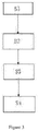
Figure 3 is a workflow chart of a servo control system provided by an embodiment of the present invention; - The reference numbers in the drawings represent:
1-feeding equipment; 2-suction roller; 3-rubber coating roller; 4-first scraper; 5-second scraper; 6-cleaning device; 61-liquid feed tank; 62- transfer pump; 63- transfer pipe; 64-spay pipe; 65-spay hole; 67- recovery tank; 68- filter; 7-support roller - As shown in
Figure 1 , this embodiment provides a patterned steel plate with a single-ground colour by using roller-coating printing and screen printing, comprising in sequence the following process steps of - A. preparing a steel strip to be printed, wherein a decoiler is used to decoil and trim the steel strip and a seamer is used to seam the decoiled steel strip;
- B. using a roller printing unit to perform a roller printing on the steel strip to be printed and forming a single-ground colour;
- C. placing the steel strip having the patterns with single-ground colour formed thereon on a printing table and performing screen printing, so as to produce a pattern with a specific shape on the steel strip having the pattern with single-ground colour;
- S1. inputting data of diameter of each roller and a process speed of the first roller printing unit into a PLC control module, then calculating out theoretical roller surface linear velocity of each roller (the specific calculating method: theoretical rotation speed = process speed/π* diameter of each roller, theoretical roller surface linear velocity = theoretical rotation speed* roller diameter *π) by the PLC control module according to the process speed and the diameter of each roller, allowing the theoretical roller surface linear velocity of each roller to be consistent with the process speed, and outputting the calculated theoretical roll surface linear velocity signal of each roller into a servo control module having an encoder;
- S2. receiving the theoretical roll surface linear velocity signal of each roller by the servo control module from the PLC control module and driving each roller according to the theoretical roll surface linear velocity signal;
- S3. collecting actual roller surface linear velocity of each roller by the encoder and outputting the actual roller surface linear velocity signal of each roller into the PLC control module;
- S4. according to the received actual roller surface linear velocity signal and theoretical roller surface linear velocity signal of each roller, adjusting current frequency of electrical machine for driving each roller, and adjusting the actual roller surface linear velocity of each roller to be consistent with the theoretical roller surface linear velocity of each roller by the PLC control module, thereby completing the roller printing of the roller printing unit and forming a single-ground colour on the steel plate.
- As an alternative embodiment, two units of roller printing equipments are prepared for roller printing two-ground colour, particularly, in order to realize continuous operation of adjacent roller printing units on line, in the sub-step S1, data of distance between the first roller printing unit and the second roller printing unit is input into the PLC control module, and on the basis of the process speed and the data of distance, the PLC control module calculates out a time to start the second roller printing unit, and starts the second roller printing unit according to the time, and then the second roller printing of the second roller printing unit is completed. More particularly, in order to print irregular long patterns, after completing the printing of the second roller printing unit, that is, after the step S4, the printed patterns are collected by a code recognition module, and a pattern misplacement distance is determined by a computer recognition system, and then the process speed of the corresponding roller printing unit is revised. The revision process is described in detail as below. If the actual position of a latter printed colour in the patterns collected by the code recognition module misplaces a distance from the predetermined position of the latter printed colour relative to the former printed colour , for example, the actual position locates at 10mm ahead of the predetermined position, which indicates that the actual process speed (denoted by VI) of the roller delivering the steel strip speeds up 10mm per unit time relative to the theoretical process speed (denoted by V2), that is at this time, V2=V1-10, thus calculating out V2. Then the calculated V2 is converted into the theoretical rotation speed of the roller (denoted by N) via the formula N=V2/π*roller diameter, thereby adjusting the current frequency of the corresponding electric machine in accordance with rotation speed N, thus the rotation speed of the corresponding roller will be adjusted, and the process speed will be further adjusted, and finally the pattern misplacement accuracy is controlled within ±0.6 millimeter. This adjusting process is a dynamic and repeated process. Herein, the printed patterns are collected by a digital video comprised in the code recognition module.
- In the present embodiment, as the flattening device is arranged at a bottom of the printing table, and the flattening device is able to flatten the strip steel that is cold rolled and/or hot rolled and further is shaped by being sheared, so as to allow the scraper to perform ink coating transfer under a uniform force, which reduces the difficulty of screen printing. Since the flattening device is arranged at the bottom of the printing table, before the screen printing of step D, the flattening device is used to flatten the strip steel. The process of flattening is provided in detail as follows: the printing table is made of ferromagnetic material, and a magnet coil is arranged at a lower part of the printing table corresponding to a placement position of the strip steel and is connected with an energizing control device which is controlled to make the magnet coil energized when flattening so that the printing table is magnetized and the magnetized printing table attracts the strip steel and flattens the same.
- In order to improve the formability of the printed steel strip, the present embodiment preferably comprises a step of pre-processing the steel strip to be printed before roller printing between the step A and step B, and the pre-processing before roller printing comprises in sequence the following steps of in the degreasing treatment, an alkali liquor with an concentration of 1% and an the degreasing is performed at the temperature of 50-65 degrees so as to remove oil and dust from the surface of the strip steel, and in the alkali liquor, the ratio of total alkali to free alkali is less than 2.5; in the cleaning treatment, desalted water having a temperature of 50-65 degrees and a PH value less than 7.8 is used to wash the surface of the strip steel after degreasing treatment, so as to remove residual alkali liquor on surface of the strip steel; in a first drying treatment, hot air having a temperature of 75-85 degrees heated by a vapor heat exchanger is used to dry the surface of the strip steel after cleaning so as to remove residual water thereon; in the passivating treatment, the surface of the strip steel after cleaning is passivated with a treating solution having Chromium weight of 22-32, so as to increase the adhesion force between the strip steel and the primer paint and also increase the antiseptic property; in a second drying treatment, the passivated surface is dried by an electrical heating oven at a baking temperature of 75-85 degrees, in order to enhance passivation effect. In the coating primer paint treatment, the first roller printing unit is used to coat primer paint and back paint on the surface of the strip steel, and the colour and the property of the primer paint depend on the patterns to be printed; in the baking for curing treatment and first cooling treatment, the strip steel coated with the primer paint and the back paint is baked to allow the primer paint and the back paint to be fully dried at temperature of 214-232 degrees, then the strip steel is cooled by water spay and flow to further stabilize the property of the primer paint and the back paint.
- In the present embodiment, in order to improve brightness of the ground-colour patterns and protection for the same, a post processing treatment is performed to the steel strip in the step C, and the post processing treatment comprises steps of spraying gloss paint on the surface of the steel strip, and then performing a third drying treatment, followed by a second cooling treatment.
- In the present embodiment, in order to let the produced steel strip be convenient for storage and transport, a recoiler is used to coil the steel strip after completing all the roller printing.
- It should be noted that, for the production method of the above patterned steel plate with a single-ground colour of the present invention, roller printing units are required for carrying out the step B, but there is no limitation to the specific structure of the roller printing units.
- This embodiment provides a method for producing a patterned steel plate with a single-ground colour by using roller-coating printing and screen printing, and the method is a variation of production method of embodiment 1, in which the flattening method of the steel strip is different from embodiment 1. In the present embodiment, the detailed flattening method of the steel strip is introduced as follows: a plurality of through holes are arranged at the printing table corresponding to a placement position of the strip steel, and a fan is arranged at a bottom of the printing table and adapted for sucking air through the through holes when flattening, so as to form negative pressure in a clearance space formed by the strip steel and the printing table, and the strip steel is further pressed towards the printing table, and the flattening is completed.
- The present embodiment provides a structure of the roller printing unit used in the step B in the embodiment 1. As shown in
Figure 2 , the roller printing unit comprises a feeding equipment 1 used for providing paints; asuction roller 2, whose circumferential surface is in connection with the feeding equipment 1, and has a plurality of recesses adapted for being filled with paints for forming an image area; a rubber-coating roller 3, with its circumferential surface in connection with thesuction roller 2, used for receiving and roller printing the image area formed by the paints on thecoating roller 3 onto a steel plate; afirst scraper 4, arranged on a first scraper support and contacting with thesuction roller 2 at a specific angle, used for scraping off paints outside the image area on thesuction roller 2; and a second scraper 5, arranged on the second scraper support and contacting with thecoating roller 3 at a specific angle, used for scraping off paints outside the image area on therubber coating roller 3. - The working process of the roller printing unit in the present embodiment is described as below. The
suction roller 2 runs, and the feeding equipment 1 supplies thesuction roller 2 with paints. A part of the paints gets into the recesses used for forming an image area on thesuction roller 2, and another part of the paints locates outside the recesses on thesuction roller 2. The paints outside the recesses on thesuction roller 2 is scraped off by thefirst scraper 4, then thesuction roller 2 rotates to transfer the paints in the recesses onto the rubber-coating roller 3 to form an image area. Then the paints outside the image area on therubber coating roller 3 is scraped off by the second scraper, then therubber coating roller 3 rotates to transfer the image area onto the metal plate to be printed to form a pattern. The metal plate to be printed is supported by a support roller 7 which also provides a supporting force for the coating operation of the rubber coating roller. - The method for producing a patterned steel plate with a single-ground colour by using the roller printing units of the present embodiment is introduced as follows:
- A. preparing a steel strip to be printed, wherein a decoiler is used to decoil and trim the steel strip and a seamer is used to seam the decoiled steel strip;
- B. using a roller printing unit to perform a roller printing on the steel strip to be printed and forming a single-ground colour;
- C. placing the steel strip having the patterns with single-ground colour formed thereon on a printing table and performing screen printing, so as to produce a pattern with a specific shape on the steel strip having the pattern with single-ground colour;
- S1. inputting data of diameter of the
suction roller 2 and thecoating roller 3 and the process speed of the roller printing unit into a PLC control module, then calculating out theoretical roller surface linear velocity of thesuction roller 2 and thecoating roller 3 by the PLC control module according to the process speed and the diameter of thesuction roller 2 and thecoating roller 3, allowing the theoretical roller surface linear velocity of thesuction roller 2 and thecoating roller 3 to be consistent with the process speed, and outputting the calculated theoretical roller surface linear velocity signal of thesuction roller 2 into a first servo control module having a first encoder, and outputs the theoretical roller surface linear velocity signal of thecoating roller 3 into a second servo control module having a second encoder; - S2. receiving the theoretical roller surface linear velocity signal of the
suction roller 2 by the first servo control module from the PLC control module and according to the signal, driving thesuction roller 2; receiving the theoretical roller surface linear velocity signal of thecoating roller 3 by the second servo control module from the PLC control module and according to the signal, driving thecoating roller 3; - S3. collecting the actual roller surface linear velocity of the
suction roller 2 by the first encoder and outputting the actual roller surface linear velocity signal of thesuction roller 2 into the PLC control module, and collecting the actual roller surface linear velocity of thecoating roller 3 by the first encoder and outputting the actual roller surface linear velocity signal of thecoating roller 3 into the PLC control module; - S4. according to the received actual roller surface linear velocity signal and the theoretical roller surface linear velocity signal of the
suction roller 2 and thecoating roller 3, adjusting current frequency of electrical machine and adjusting the actual roller surface linear velocity of thesuction roller 2 and thecoating roller 3 to be consistent with the theoretical roller surface linear velocity of thesuction roller 2 and thecoating roller 3 by the PLC control module, thereby completing the roller printing of the roller printing unit. - The
rubber coating roller 3 of the roller printing unit of the present embodiment is made of rubber, and such a design of structure allows the rubber coating roller to flexibly contact with thesuction roller 2 and the steel plate to be printed respectively, thus ensuring an exactly matching contact. In this way, the image area on thesuction roller 2 can be completely transferred onto therubber coating roller 3, and the image area on therubber coating roller 3 can be completely transferred onto the steel plate to be printed, thus forming a complete image area. Moreover, the intaglio printing machine provided in the present embodiment comprises afirst scraper 4 and a second scraper 5 (Figure 1 is a schematic diagram showing thefirst scraper 4 in contact with thesuction roller 2 and the second scraper 5 in contact with the rubber coating roller 3). Thefirst scraper 4 is used to scrape off the paints outside the recesses on thesuction roller 2, and the second scraper 5 is used to scrape off the paints outside the image area on therubber coating roller 3, thus avoiding the defect of lower labor efficiency caused by manual scrape, thereby improving labor efficiency. In addition, thefirst scraper 4 and the second scraper 5 are contacting with thesuction roller 2 and therubber coating roller 3 at a specific angle respectively, which can ensure better effect of scraping and prolonging the service life of the scraper. - It should be noted that, the coating roller may also be made of other materials as well as rubber, as long as the materials can ensure normal coating and flexible contact with the suction roller and the steel plate to be printed, such as silicone products which can meet requirements for elasticity, hardness and transfer property during coating.
- In the present embodiment, the
first scraper 4 contacts with thesuction roller 2 at an angle less than 30 degrees, and the second scraper 5 contacts with thecoating roller 3 at an angle more than 30 degrees. During intaglio printing process, paints that need to be scraped off are located on different positions at a same moment, so thefirst scraper 4 and the second scraper 5 are set at different angles, thus ensuring paints on thesuction roller 2 and thecoating roller 3 can be scraped off at the same time. - In the present embodiment, the
first scraper 4 is made from titanium steel plate and has a blade thickness of 0.3mm, and the second scraper 5 is made from titanium steel plate and has a blade thickness of 0.3mm. - In the present embodiment, in order to improve the performance of the roller printing unit, a cleaning device 6 is provided for cleaning the paints on second scraper 5 and the
rubber coating roller 3. The cleaning device 6 comprises aliquid feed tank 61, atransfer pump 62 used for pumping the cleaning liquid in theliquid feed tank 61, a cleaningliquid transfer pipe 63 communicated with the cleaningliquid transfer pump 62, and aspay pipe 64 communicated with the cleaning liquid transfer pipe. Thespay pipe 64 is arranged above therubber coating roller 3 in the axial direction and has a plurality of spay holes 65 thereon. The cleaning device 6 further comprises a cleaningliquid recovery tank 66, arranged below thecoating roller 3 and connected with arecovery pipe 67 leading to theliquid feed tank 61. Afilter 68 is arranged between therecovery pipe 67 and theliquid feed tank 61. - The working process of the cleaning device 6 provided in the present embodiment is described as below:
The cleaning liquid in theliquid feed tank 61 is pumped to thespay pipe 64 by thetransfer pump 62, and is sprayed through the spray holes 65, subsequently the cleaning liquid flows over therubber coating roller 3 and flows into therecovery tank 66, then passes through therecovery pipe 67 and is filtered by thefilter 68, and finally gets back to theliquid feed tank 61 for recycling. - In the present embodiment, the feeding equipment 1 is a tray with a groove.
in the step B, a servo control system is used to control the roller printing unit, and the servo control system has a following control process as shown in
Claims (5)
- A method for producing a patterned steel plate with a single-ground colour by using roller printing and screen printing, at least comprising in sequence the following process steps ofA. preparing a steel strip to be printed;B. using a roller printing unit to perform a roller printing on the steel strip to be printed and forming a single-ground colour;C. placing the steel strip with the single-ground colour formed thereon on a printing table and performing screen printing, so as to produce a pattern with a specific shape on the steel strip having the pattern with the single-ground colour;wherein in the step B, a servo control system is used to control the roller printing unit, and the servo control system has the following control process ofS1. inputting data of diameter of each roller of the roller printing unit and a process speed of the roller printing unit into a PLC control module, then calculating out theoretical roller surface linear velocity of each roller of the roller printing unit by the PLC control module according to the process speed and the diameter of each roller of the roller printing unit, allowing the theoretical roller surface linear velocity of each roller of the roller printing unit to be consistent with the process speed, and outputting the calculated theoretical roll surface linear velocity signal of each roller of the roller printing unit into a servo control module having an encoder;S2. receiving the theoretical roll surface linear velocity signal of each roller by the servo control module from the PLC control module and driving each roller according to the theoretical roll surface linear velocity signal;S3. collecting actual roller surface linear velocity of each roller by the encoder and outputting the actual roller surface linear velocity signal of each roller into the PLC control module;S4. according to the received actual roller surface linear velocity signal and theoretical roller surface linear velocity signal of each roller, adjusting a current frequency of an electrical machine for driving each roller, and adjusting the actual roller surface linear velocity of each roller to be consistent with the theoretical roller surface linear velocity of each roller by the PLC control module, thereby completing the roller printing of the roller printing unit;wherein, a flattening device is arranged at a bottom of the printing table, and used to flatten the surface of strip steel before the screen printing of step C,
wherein, the printing table is made of ferromagnetic material, and a magnet coil is arranged at a lower part of the printing table corresponding to a placement position of the strip steel and is connected with an energizing control device which is controlled to make the magnet coil energized when flattening so that the printing table is magnetized and the magnetized printing table attracts the strip steel and flattens the same, or
a plurality of through holes are arranged at the printing table corresponding to a placement position of the strip steel, and a fan is arranged at the bottom of the printing table and adapted for sucking air through the through holes when flattening, so as to form negative pressure in a clearance space formed by the strip steel and the printing table, and the strip steel is further pressed towards the printing table, and the flattening is completed. - The method of claim 1, characterized by further comprising a step of corona treatment on the strip steel prior to the step of roller printing.
- The method of claim 2, characterized by further comprising a step of electrostatic precipitation treatment between the corona treatment step and the roller printing step.
- The method of claim 3, characterized in that, in the step A, a decoiler is used to decoil and trim the steel strip and a seamer is used to seam the decoiled steel strip.
- The method of claim 4, characterized by further comprising a step of pre-processing the steel strip to be printed before roller printing between the step A and the step of corona treatment, wherein, the pre-processing comprises in sequence the following steps of degreasing treatment, cleaning treatment, first drying treatment, passivating treatment and second drying treatment.
Applications Claiming Priority (2)
| Application Number | Priority Date | Filing Date | Title |
|---|---|---|---|
| CN201310075984.5A CN103158380B (en) | 2013-03-11 | 2013-03-11 | Integrate the production method of single background color figure code steel plate of roller coat and serigraphy |
| PCT/CN2013/078408 WO2014139248A1 (en) | 2013-03-11 | 2013-06-28 | Method for producing steel plate with single-ground-color patterns by combining roller-coating printing and screen printing |
Publications (3)
| Publication Number | Publication Date |
|---|---|
| EP2974875A1 EP2974875A1 (en) | 2016-01-20 |
| EP2974875A4 EP2974875A4 (en) | 2016-04-27 |
| EP2974875B1 true EP2974875B1 (en) | 2019-02-20 |
Family
ID=48582143
Family Applications (1)
| Application Number | Title | Priority Date | Filing Date |
|---|---|---|---|
| EP13877889.9A Not-in-force EP2974875B1 (en) | 2013-03-11 | 2013-06-28 | Method for producing steel plate with single-ground-color patterns by combining roller-coating printing and screen printing |
Country Status (5)
| Country | Link |
|---|---|
| US (1) | US9486994B2 (en) |
| EP (1) | EP2974875B1 (en) |
| KR (1) | KR101764045B1 (en) |
| CN (1) | CN103158380B (en) |
| WO (1) | WO2014139248A1 (en) |
Families Citing this family (6)
| Publication number | Priority date | Publication date | Assignee | Title |
|---|---|---|---|---|
| CN103029502B (en) * | 2012-11-23 | 2015-05-27 | 辽宁超烁图码科技板业有限公司 | Production method of multicolor pattern color steel plate |
| CN103158380B (en) * | 2013-03-11 | 2015-10-07 | 辽宁超烁图码科技板业有限公司 | Integrate the production method of single background color figure code steel plate of roller coat and serigraphy |
| CN103204011B (en) | 2013-03-19 | 2016-06-01 | 辽宁超烁图码科技板业有限公司 | The roller coat production method of a kind of figure code warming plate being applicable to skin |
| DE102014109548A1 (en) | 2014-07-08 | 2016-01-14 | Thyssenkrupp Ag | Strip coating process for producing a semi-finished product having a surface structure |
| CN106168005B (en) * | 2016-08-28 | 2017-09-01 | 维尔美纸业(重庆)有限公司 | A kind of Multifunctional ad paper Intelligent Production System |
| CN106274046A (en) * | 2016-10-11 | 2017-01-04 | 东莞市锦想机械有限公司 | A kind of full-automatic printer |
Family Cites Families (26)
| Publication number | Priority date | Publication date | Assignee | Title |
|---|---|---|---|---|
| USRE25134E (en) * | 1962-03-13 | Rotary printing press for continuous metal strip | ||
| US1999413A (en) * | 1931-08-12 | 1935-04-30 | Du Pont | Method of decorating surfaces |
| DE3202800C1 (en) * | 1982-01-28 | 1983-08-11 | Daimler-Benz Ag, 7000 Stuttgart | Use of the screen printing method and device for locally specific application of lubricant to deep-drawn sheet metal panels |
| KR940013826A (en) * | 1992-12-16 | 1994-07-16 | 김영생 | Magnetic adsorption stereo printing machine |
| JPH07156363A (en) * | 1993-12-02 | 1995-06-20 | Toshiba Corp | Printer, printing method and printing mask |
| KR0125473B1 (en) * | 1994-10-25 | 1997-12-26 | 이희종 | Stainless sheet having colorful and cubic surfaces and method therefor |
| JPH09234404A (en) * | 1996-02-29 | 1997-09-09 | Sumitomo Metal Ind Ltd | Roll coater type coating device |
| JPH09299843A (en) * | 1996-05-15 | 1997-11-25 | Nkk Corp | Roll coating method for metal belt and apparatus |
| JP3064926B2 (en) * | 1996-09-24 | 2000-07-12 | 株式会社ノリタケカンパニーリミテド | Screen printing method and screen printing machine |
| CN1183274C (en) * | 2000-03-17 | 2005-01-05 | 李昌源 | Multicolored steel sheet mfg. method and system |
| JP3488866B2 (en) * | 2000-10-26 | 2004-01-19 | 株式会社淀川製鋼所 | Metal plate printing method and apparatus |
| CN2598748Y (en) * | 2002-12-12 | 2004-01-14 | 鸿富锦精密工业(深圳)有限公司 | Screen printer and printing table |
| DE10343411B4 (en) * | 2003-09-19 | 2009-07-23 | Gallus Druckmaschinen Gmbh | Rotary printing machine and method for making freely accessible a printing cylinder or a linear guide cylinder |
| CN101570079B (en) * | 2009-06-23 | 2014-10-01 | 葛爱民 | Transfer line of steel strip printing and process thereof |
| CN201410848Y (en) * | 2009-06-23 | 2010-02-24 | 葛爱民 | Continuous production line in steel strip printing |
| CN101602046A (en) * | 2009-07-03 | 2009-12-16 | 创志钢铁(中山)有限公司 | Produce the method for color-coated printed steel plate continuously |
| CN201592348U (en) * | 2010-01-27 | 2010-09-29 | 葛勇智 | Multicolor steel plate continuous production line |
| CN101745815B (en) * | 2010-01-27 | 2014-09-03 | 葛爱民 | Continuous printing production line of steel plate |
| CN101786389B (en) * | 2010-01-27 | 2011-05-04 | 葛勇智 | Multicolor steel-plate continuous production line |
| CN201823685U (en) * | 2010-09-17 | 2011-05-11 | 浙江龙驰防腐技术有限公司 | Uniform speed control device for automatically adjusting forwarding speed of steel pipe |
| KR101183201B1 (en) * | 2010-11-04 | 2012-09-14 | 이학연 | Manufacturing Apparatus for Multi-Colored Steel Sheet |
| CN102580903B (en) * | 2011-01-18 | 2014-01-22 | 宝山钢铁股份有限公司 | Production method of single-side double-color coated steel plates for household electric appliances |
| CN202753569U (en) * | 2012-07-13 | 2013-02-27 | 张俊 | Production system for multi-color screen-printing color-coated steel sheets |
| CN103158380B (en) * | 2013-03-11 | 2015-10-07 | 辽宁超烁图码科技板业有限公司 | Integrate the production method of single background color figure code steel plate of roller coat and serigraphy |
| CN103158339B (en) * | 2013-03-11 | 2015-05-27 | 辽宁超烁图码科技板业有限公司 | Screen printing production line of image coding steel plate |
| CN103158381B (en) * | 2013-03-11 | 2015-06-17 | 辽宁超烁图码科技板业有限公司 | Production method of graph code steel plate integrating roller painting printing and silk-screen printing into whole |
-
2013
- 2013-03-11 CN CN201310075984.5A patent/CN103158380B/en not_active Expired - Fee Related
- 2013-06-28 EP EP13877889.9A patent/EP2974875B1/en not_active Not-in-force
- 2013-06-28 WO PCT/CN2013/078408 patent/WO2014139248A1/en active Application Filing
- 2013-06-28 KR KR1020157028695A patent/KR101764045B1/en active IP Right Grant
- 2013-06-28 US US14/774,993 patent/US9486994B2/en not_active Expired - Fee Related
Non-Patent Citations (1)
| Title |
|---|
| None * |
Also Published As
| Publication number | Publication date |
|---|---|
| US20160082714A1 (en) | 2016-03-24 |
| EP2974875A4 (en) | 2016-04-27 |
| WO2014139248A1 (en) | 2014-09-18 |
| US9486994B2 (en) | 2016-11-08 |
| KR20150129815A (en) | 2015-11-20 |
| CN103158380B (en) | 2015-10-07 |
| KR101764045B1 (en) | 2017-08-01 |
| CN103158380A (en) | 2013-06-19 |
| EP2974875A1 (en) | 2016-01-20 |
Similar Documents
| Publication | Publication Date | Title |
|---|---|---|
| EP2974864B1 (en) | Method for producing steel plate with patterns by combining roller printing and screen printing | |
| EP2974875B1 (en) | Method for producing steel plate with single-ground-color patterns by combining roller-coating printing and screen printing | |
| EP2923856B1 (en) | Method of producing variegated steel plate with multicoloured pattern | |
| EP2974881B1 (en) | Method for producing a roller-printing colour steel plate with multicoloured patterns | |
| EP2823967B1 (en) | Roller printing manufacturing method for patterned thermal insulation panel applicable in outer wall of building | |
| EP1952987B1 (en) | Process for controlling a sheet processing machine | |
| CN102216082A (en) | Flexographic printing method and flexographic printing apparatus | |
| CN102991113B (en) | Manufacture method for roller coating color plate | |
| US20150343479A1 (en) | Control method and control system used for roller coating printing production line | |
| CN103158339B (en) | Screen printing production line of image coding steel plate | |
| US9383658B2 (en) | Roll-printing apparatus and roll-printing method using the same | |
| CN208789244U (en) | A kind of valley printing equipment | |
| CN103287064A (en) | Improved screen print production line of figure-number steel plates | |
| CN108928110A (en) | A kind of valley printing equipment and its embossed method |
Legal Events
| Date | Code | Title | Description |
|---|---|---|---|
| PUAI | Public reference made under article 153(3) epc to a published international application that has entered the european phase |
Free format text: ORIGINAL CODE: 0009012 |
|
| 17P | Request for examination filed |
Effective date: 20151012 |
|
| AK | Designated contracting states |
Kind code of ref document: A1 Designated state(s): AL AT BE BG CH CY CZ DE DK EE ES FI FR GB GR HR HU IE IS IT LI LT LU LV MC MK MT NL NO PL PT RO RS SE SI SK SM TR |
|
| AX | Request for extension of the european patent |
Extension state: BA ME |
|
| REG | Reference to a national code |
Ref country code: DE Ref legal event code: R079 Ref document number: 602013051232 Country of ref document: DE Free format text: PREVIOUS MAIN CLASS: B41M0001120000 Ipc: B41F0009060000 |
|
| A4 | Supplementary search report drawn up and despatched |
Effective date: 20160331 |
|
| RIC1 | Information provided on ipc code assigned before grant |
Ipc: B41F 15/26 20060101ALI20160318BHEP Ipc: B41M 1/12 20060101ALI20160318BHEP Ipc: B41M 1/14 20060101ALI20160318BHEP Ipc: B41F 33/00 20060101ALI20160318BHEP Ipc: B41M 1/28 20060101ALI20160318BHEP Ipc: B41F 15/20 20060101ALI20160318BHEP Ipc: B41F 19/00 20060101ALI20160318BHEP Ipc: B41F 9/06 20060101AFI20160318BHEP Ipc: B41F 23/00 20060101ALI20160318BHEP Ipc: B41M 1/10 20060101ALI20160318BHEP |
|
| DAX | Request for extension of the european patent (deleted) | ||
| INTG | Intention to grant announced |
Effective date: 20180611 |
|
| GRAP | Despatch of communication of intention to grant a patent |
Free format text: ORIGINAL CODE: EPIDOSNIGR1 |
|
| STAA | Information on the status of an ep patent application or granted ep patent |
Free format text: STATUS: GRANT OF PATENT IS INTENDED |
|
| GRAS | Grant fee paid |
Free format text: ORIGINAL CODE: EPIDOSNIGR3 |
|
| GRAA | (expected) grant |
Free format text: ORIGINAL CODE: 0009210 |
|
| STAA | Information on the status of an ep patent application or granted ep patent |
Free format text: STATUS: THE PATENT HAS BEEN GRANTED |
|
| AK | Designated contracting states |
Kind code of ref document: B1 Designated state(s): AL AT BE BG CH CY CZ DE DK EE ES FI FR GB GR HR HU IE IS IT LI LT LU LV MC MK MT NL NO PL PT RO RS SE SI SK SM TR |
|
| REG | Reference to a national code |
Ref country code: GB Ref legal event code: FG4D |
|
| REG | Reference to a national code |
Ref country code: CH Ref legal event code: EP |
|
| REG | Reference to a national code |
Ref country code: AT Ref legal event code: REF Ref document number: 1097663 Country of ref document: AT Kind code of ref document: T Effective date: 20190315 |
|
| REG | Reference to a national code |
Ref country code: IE Ref legal event code: FG4D |
|
| REG | Reference to a national code |
Ref country code: DE Ref legal event code: R096 Ref document number: 602013051232 Country of ref document: DE |
|
| REG | Reference to a national code |
Ref country code: NL Ref legal event code: MP Effective date: 20190220 |
|
| REG | Reference to a national code |
Ref country code: LT Ref legal event code: MG4D |
|
| PG25 | Lapsed in a contracting state [announced via postgrant information from national office to epo] |
Ref country code: PT Free format text: LAPSE BECAUSE OF FAILURE TO SUBMIT A TRANSLATION OF THE DESCRIPTION OR TO PAY THE FEE WITHIN THE PRESCRIBED TIME-LIMIT Effective date: 20190620 Ref country code: SE Free format text: LAPSE BECAUSE OF FAILURE TO SUBMIT A TRANSLATION OF THE DESCRIPTION OR TO PAY THE FEE WITHIN THE PRESCRIBED TIME-LIMIT Effective date: 20190220 Ref country code: NO Free format text: LAPSE BECAUSE OF FAILURE TO SUBMIT A TRANSLATION OF THE DESCRIPTION OR TO PAY THE FEE WITHIN THE PRESCRIBED TIME-LIMIT Effective date: 20190520 Ref country code: LT Free format text: LAPSE BECAUSE OF FAILURE TO SUBMIT A TRANSLATION OF THE DESCRIPTION OR TO PAY THE FEE WITHIN THE PRESCRIBED TIME-LIMIT Effective date: 20190220 Ref country code: FI Free format text: LAPSE BECAUSE OF FAILURE TO SUBMIT A TRANSLATION OF THE DESCRIPTION OR TO PAY THE FEE WITHIN THE PRESCRIBED TIME-LIMIT Effective date: 20190220 Ref country code: NL Free format text: LAPSE BECAUSE OF FAILURE TO SUBMIT A TRANSLATION OF THE DESCRIPTION OR TO PAY THE FEE WITHIN THE PRESCRIBED TIME-LIMIT Effective date: 20190220 |
|
| PG25 | Lapsed in a contracting state [announced via postgrant information from national office to epo] |
Ref country code: BG Free format text: LAPSE BECAUSE OF FAILURE TO SUBMIT A TRANSLATION OF THE DESCRIPTION OR TO PAY THE FEE WITHIN THE PRESCRIBED TIME-LIMIT Effective date: 20190520 Ref country code: RS Free format text: LAPSE BECAUSE OF FAILURE TO SUBMIT A TRANSLATION OF THE DESCRIPTION OR TO PAY THE FEE WITHIN THE PRESCRIBED TIME-LIMIT Effective date: 20190220 Ref country code: HR Free format text: LAPSE BECAUSE OF FAILURE TO SUBMIT A TRANSLATION OF THE DESCRIPTION OR TO PAY THE FEE WITHIN THE PRESCRIBED TIME-LIMIT Effective date: 20190220 Ref country code: IS Free format text: LAPSE BECAUSE OF FAILURE TO SUBMIT A TRANSLATION OF THE DESCRIPTION OR TO PAY THE FEE WITHIN THE PRESCRIBED TIME-LIMIT Effective date: 20190620 Ref country code: LV Free format text: LAPSE BECAUSE OF FAILURE TO SUBMIT A TRANSLATION OF THE DESCRIPTION OR TO PAY THE FEE WITHIN THE PRESCRIBED TIME-LIMIT Effective date: 20190220 Ref country code: GR Free format text: LAPSE BECAUSE OF FAILURE TO SUBMIT A TRANSLATION OF THE DESCRIPTION OR TO PAY THE FEE WITHIN THE PRESCRIBED TIME-LIMIT Effective date: 20190521 |
|
| REG | Reference to a national code |
Ref country code: AT Ref legal event code: MK05 Ref document number: 1097663 Country of ref document: AT Kind code of ref document: T Effective date: 20190220 |
|
| PG25 | Lapsed in a contracting state [announced via postgrant information from national office to epo] |
Ref country code: RO Free format text: LAPSE BECAUSE OF FAILURE TO SUBMIT A TRANSLATION OF THE DESCRIPTION OR TO PAY THE FEE WITHIN THE PRESCRIBED TIME-LIMIT Effective date: 20190220 Ref country code: IT Free format text: LAPSE BECAUSE OF FAILURE TO SUBMIT A TRANSLATION OF THE DESCRIPTION OR TO PAY THE FEE WITHIN THE PRESCRIBED TIME-LIMIT Effective date: 20190220 Ref country code: SK Free format text: LAPSE BECAUSE OF FAILURE TO SUBMIT A TRANSLATION OF THE DESCRIPTION OR TO PAY THE FEE WITHIN THE PRESCRIBED TIME-LIMIT Effective date: 20190220 Ref country code: AL Free format text: LAPSE BECAUSE OF FAILURE TO SUBMIT A TRANSLATION OF THE DESCRIPTION OR TO PAY THE FEE WITHIN THE PRESCRIBED TIME-LIMIT Effective date: 20190220 Ref country code: DK Free format text: LAPSE BECAUSE OF FAILURE TO SUBMIT A TRANSLATION OF THE DESCRIPTION OR TO PAY THE FEE WITHIN THE PRESCRIBED TIME-LIMIT Effective date: 20190220 Ref country code: EE Free format text: LAPSE BECAUSE OF FAILURE TO SUBMIT A TRANSLATION OF THE DESCRIPTION OR TO PAY THE FEE WITHIN THE PRESCRIBED TIME-LIMIT Effective date: 20190220 Ref country code: ES Free format text: LAPSE BECAUSE OF FAILURE TO SUBMIT A TRANSLATION OF THE DESCRIPTION OR TO PAY THE FEE WITHIN THE PRESCRIBED TIME-LIMIT Effective date: 20190220 Ref country code: CZ Free format text: LAPSE BECAUSE OF FAILURE TO SUBMIT A TRANSLATION OF THE DESCRIPTION OR TO PAY THE FEE WITHIN THE PRESCRIBED TIME-LIMIT Effective date: 20190220 |
|
| REG | Reference to a national code |
Ref country code: DE Ref legal event code: R097 Ref document number: 602013051232 Country of ref document: DE |
|
| PG25 | Lapsed in a contracting state [announced via postgrant information from national office to epo] |
Ref country code: SM Free format text: LAPSE BECAUSE OF FAILURE TO SUBMIT A TRANSLATION OF THE DESCRIPTION OR TO PAY THE FEE WITHIN THE PRESCRIBED TIME-LIMIT Effective date: 20190220 Ref country code: PL Free format text: LAPSE BECAUSE OF FAILURE TO SUBMIT A TRANSLATION OF THE DESCRIPTION OR TO PAY THE FEE WITHIN THE PRESCRIBED TIME-LIMIT Effective date: 20190220 |
|
| PLBE | No opposition filed within time limit |
Free format text: ORIGINAL CODE: 0009261 |
|
| STAA | Information on the status of an ep patent application or granted ep patent |
Free format text: STATUS: NO OPPOSITION FILED WITHIN TIME LIMIT |
|
| PG25 | Lapsed in a contracting state [announced via postgrant information from national office to epo] |
Ref country code: AT Free format text: LAPSE BECAUSE OF FAILURE TO SUBMIT A TRANSLATION OF THE DESCRIPTION OR TO PAY THE FEE WITHIN THE PRESCRIBED TIME-LIMIT Effective date: 20190220 |
|
| REG | Reference to a national code |
Ref country code: DE Ref legal event code: R119 Ref document number: 602013051232 Country of ref document: DE |
|
| 26N | No opposition filed |
Effective date: 20191121 |
|
| PG25 | Lapsed in a contracting state [announced via postgrant information from national office to epo] |
Ref country code: MC Free format text: LAPSE BECAUSE OF FAILURE TO SUBMIT A TRANSLATION OF THE DESCRIPTION OR TO PAY THE FEE WITHIN THE PRESCRIBED TIME-LIMIT Effective date: 20190220 |
|
| REG | Reference to a national code |
Ref country code: CH Ref legal event code: PL |
|
| GBPC | Gb: european patent ceased through non-payment of renewal fee |
Effective date: 20190628 |
|
| PG25 | Lapsed in a contracting state [announced via postgrant information from national office to epo] |
Ref country code: SI Free format text: LAPSE BECAUSE OF FAILURE TO SUBMIT A TRANSLATION OF THE DESCRIPTION OR TO PAY THE FEE WITHIN THE PRESCRIBED TIME-LIMIT Effective date: 20190220 |
|
| REG | Reference to a national code |
Ref country code: BE Ref legal event code: MM Effective date: 20190630 |
|
| PG25 | Lapsed in a contracting state [announced via postgrant information from national office to epo] |
Ref country code: TR Free format text: LAPSE BECAUSE OF FAILURE TO SUBMIT A TRANSLATION OF THE DESCRIPTION OR TO PAY THE FEE WITHIN THE PRESCRIBED TIME-LIMIT Effective date: 20190220 |
|
| PG25 | Lapsed in a contracting state [announced via postgrant information from national office to epo] |
Ref country code: DE Free format text: LAPSE BECAUSE OF NON-PAYMENT OF DUE FEES Effective date: 20200101 Ref country code: IE Free format text: LAPSE BECAUSE OF NON-PAYMENT OF DUE FEES Effective date: 20190628 Ref country code: GB Free format text: LAPSE BECAUSE OF NON-PAYMENT OF DUE FEES Effective date: 20190628 |
|
| PG25 | Lapsed in a contracting state [announced via postgrant information from national office to epo] |
Ref country code: BE Free format text: LAPSE BECAUSE OF NON-PAYMENT OF DUE FEES Effective date: 20190630 Ref country code: LU Free format text: LAPSE BECAUSE OF NON-PAYMENT OF DUE FEES Effective date: 20190628 Ref country code: LI Free format text: LAPSE BECAUSE OF NON-PAYMENT OF DUE FEES Effective date: 20190630 Ref country code: CH Free format text: LAPSE BECAUSE OF NON-PAYMENT OF DUE FEES Effective date: 20190630 |
|
| PG25 | Lapsed in a contracting state [announced via postgrant information from national office to epo] |
Ref country code: FR Free format text: LAPSE BECAUSE OF NON-PAYMENT OF DUE FEES Effective date: 20190630 |
|
| PG25 | Lapsed in a contracting state [announced via postgrant information from national office to epo] |
Ref country code: CY Free format text: LAPSE BECAUSE OF FAILURE TO SUBMIT A TRANSLATION OF THE DESCRIPTION OR TO PAY THE FEE WITHIN THE PRESCRIBED TIME-LIMIT Effective date: 20190220 |
|
| PG25 | Lapsed in a contracting state [announced via postgrant information from national office to epo] |
Ref country code: HU Free format text: LAPSE BECAUSE OF FAILURE TO SUBMIT A TRANSLATION OF THE DESCRIPTION OR TO PAY THE FEE WITHIN THE PRESCRIBED TIME-LIMIT; INVALID AB INITIO Effective date: 20130628 Ref country code: MT Free format text: LAPSE BECAUSE OF FAILURE TO SUBMIT A TRANSLATION OF THE DESCRIPTION OR TO PAY THE FEE WITHIN THE PRESCRIBED TIME-LIMIT Effective date: 20190220 |
|
| PG25 | Lapsed in a contracting state [announced via postgrant information from national office to epo] |
Ref country code: MK Free format text: LAPSE BECAUSE OF FAILURE TO SUBMIT A TRANSLATION OF THE DESCRIPTION OR TO PAY THE FEE WITHIN THE PRESCRIBED TIME-LIMIT Effective date: 20190220 |