EP2974006B1 - Hüllkurvennachführungssystem mit interner leistungsverstärkercharakterisierung - Google Patents
Hüllkurvennachführungssystem mit interner leistungsverstärkercharakterisierung Download PDFInfo
- Publication number
- EP2974006B1 EP2974006B1 EP14767467.5A EP14767467A EP2974006B1 EP 2974006 B1 EP2974006 B1 EP 2974006B1 EP 14767467 A EP14767467 A EP 14767467A EP 2974006 B1 EP2974006 B1 EP 2974006B1
- Authority
- EP
- European Patent Office
- Prior art keywords
- power amplifier
- supply voltage
- amplifier system
- amplitude
- vcc
- Prior art date
- Legal status (The legal status is an assumption and is not a legal conclusion. Google has not performed a legal analysis and makes no representation as to the accuracy of the status listed.)
- Active
Links
Images


Classifications
-
- H—ELECTRICITY
- H03—ELECTRONIC CIRCUITRY
- H03F—AMPLIFIERS
- H03F1/00—Details of amplifiers with only discharge tubes, only semiconductor devices or only unspecified devices as amplifying elements
- H03F1/02—Modifications of amplifiers to raise the efficiency, e.g. gliding Class A stages, use of an auxiliary oscillation
- H03F1/0205—Modifications of amplifiers to raise the efficiency, e.g. gliding Class A stages, use of an auxiliary oscillation in transistor amplifiers
- H03F1/0211—Modifications of amplifiers to raise the efficiency, e.g. gliding Class A stages, use of an auxiliary oscillation in transistor amplifiers with control of the supply voltage or current
- H03F1/0216—Continuous control
- H03F1/0222—Continuous control by using a signal derived from the input signal
-
- H—ELECTRICITY
- H03—ELECTRONIC CIRCUITRY
- H03F—AMPLIFIERS
- H03F3/00—Amplifiers with only discharge tubes or only semiconductor devices as amplifying elements
- H03F3/189—High frequency amplifiers, e.g. radio frequency amplifiers
-
- H—ELECTRICITY
- H03—ELECTRONIC CIRCUITRY
- H03F—AMPLIFIERS
- H03F1/00—Details of amplifiers with only discharge tubes, only semiconductor devices or only unspecified devices as amplifying elements
- H03F1/02—Modifications of amplifiers to raise the efficiency, e.g. gliding Class A stages, use of an auxiliary oscillation
- H03F1/0205—Modifications of amplifiers to raise the efficiency, e.g. gliding Class A stages, use of an auxiliary oscillation in transistor amplifiers
- H03F1/0211—Modifications of amplifiers to raise the efficiency, e.g. gliding Class A stages, use of an auxiliary oscillation in transistor amplifiers with control of the supply voltage or current
- H03F1/0216—Continuous control
- H03F1/0222—Continuous control by using a signal derived from the input signal
- H03F1/0227—Continuous control by using a signal derived from the input signal using supply converters
-
- H—ELECTRICITY
- H03—ELECTRONIC CIRCUITRY
- H03F—AMPLIFIERS
- H03F1/00—Details of amplifiers with only discharge tubes, only semiconductor devices or only unspecified devices as amplifying elements
- H03F1/02—Modifications of amplifiers to raise the efficiency, e.g. gliding Class A stages, use of an auxiliary oscillation
- H03F1/0205—Modifications of amplifiers to raise the efficiency, e.g. gliding Class A stages, use of an auxiliary oscillation in transistor amplifiers
- H03F1/0211—Modifications of amplifiers to raise the efficiency, e.g. gliding Class A stages, use of an auxiliary oscillation in transistor amplifiers with control of the supply voltage or current
- H03F1/0216—Continuous control
- H03F1/0233—Continuous control by using a signal derived from the output signal, e.g. bootstrapping the voltage supply
- H03F1/0238—Continuous control by using a signal derived from the output signal, e.g. bootstrapping the voltage supply using supply converters
-
- H—ELECTRICITY
- H03—ELECTRONIC CIRCUITRY
- H03F—AMPLIFIERS
- H03F1/00—Details of amplifiers with only discharge tubes, only semiconductor devices or only unspecified devices as amplifying elements
- H03F1/32—Modifications of amplifiers to reduce non-linear distortion
-
- H—ELECTRICITY
- H03—ELECTRONIC CIRCUITRY
- H03F—AMPLIFIERS
- H03F3/00—Amplifiers with only discharge tubes or only semiconductor devices as amplifying elements
- H03F3/189—High frequency amplifiers, e.g. radio frequency amplifiers
- H03F3/19—High frequency amplifiers, e.g. radio frequency amplifiers with semiconductor devices only
-
- H—ELECTRICITY
- H03—ELECTRONIC CIRCUITRY
- H03F—AMPLIFIERS
- H03F3/00—Amplifiers with only discharge tubes or only semiconductor devices as amplifying elements
- H03F3/20—Power amplifiers, e.g. Class B amplifiers, Class C amplifiers
- H03F3/21—Power amplifiers, e.g. Class B amplifiers, Class C amplifiers with semiconductor devices only
-
- H—ELECTRICITY
- H03—ELECTRONIC CIRCUITRY
- H03F—AMPLIFIERS
- H03F3/00—Amplifiers with only discharge tubes or only semiconductor devices as amplifying elements
- H03F3/20—Power amplifiers, e.g. Class B amplifiers, Class C amplifiers
- H03F3/24—Power amplifiers, e.g. Class B amplifiers, Class C amplifiers of transmitter output stages
-
- H—ELECTRICITY
- H03—ELECTRONIC CIRCUITRY
- H03F—AMPLIFIERS
- H03F2200/00—Indexing scheme relating to amplifiers
- H03F2200/102—A non-specified detector of a signal envelope being used in an amplifying circuit
-
- H—ELECTRICITY
- H03—ELECTRONIC CIRCUITRY
- H03F—AMPLIFIERS
- H03F2200/00—Indexing scheme relating to amplifiers
- H03F2200/451—Indexing scheme relating to amplifiers the amplifier being a radio frequency amplifier
Definitions
- This disclosure relates generally to envelope tracking power amplifier systems, and more specifically to envelope tracking power amplifier systems with improved characteristics.
- Envelope Tracking (ET) systems may be found in the radio frequency (RF) transmitter section of a radio where power efficiency is important, such as in cellular radios used in mobile phones.
- a typical ET system includes a variable power supply supplying a power amplifier (PA) with a dynamically changing supply voltage that tracks the amplitude of the modulation.
- PA power amplifier
- the goal of such an ET system is to improve power efficiency by operating the PA with low headroom.
- the supply voltage level can be determined with a look up table that references amplitudes to values for the supply voltage.
- FIG. 7 illustrates the nature of choices available for a lookup table.
- the lookup table may contain PA supply voltage values ranging from 1.2V to 5V. The choice of this value may be set to provide a good balance between PA efficiency and linearity. If the PA supply voltage is set too low, the PA operates with lower head room, and thus with higher efficiency, but with higher distortion. Conversely, if the PA supply voltage is set too high, the PA operates with higher head room, and thus with lower efficiency, but the additional headroom allows for lower distortion levels.
- the values for the lookup table are typically determined in a factory through characterization on a typical PA on a typical radio device under typical conditions. This initial set of values is then copied into other ET systems. However, during actual operation of the other ET systems, the PA may exhibit different characteristics from those during characterization of the typical PA, depending on factors such as PA process and manufacturing tolerances, power supply circuit variations, environmental factors, temperature, operating frequency modulation formats and antenna mismatch. Thus, the initial set of values may not operate the PA with the right balance of power efficiency and distortion.
- Embodiments of the present disclosure include a RF PA system that generates its own local characterization information.
- the RF PA system then uses the characterization information to control the supply voltage to the PA.
- the RF PA system can control the supply voltage in a manner that more accurately achieves a desired balance between power efficiency and distortion.
- the RF PA system includes a PA to generate a RF output signal from a RF input signal, the PA powered by a supply voltage.
- a characterization block generates characterization information corresponding to a relationship between the supply voltage and performance (e.g., gain, power efficiency, distortion, receive band noise) of the RF PA system for a plurality of levels of one or more operating conditions (e.g., temperature, operating frequency, modulation format, antenna mismatch, etc.) of the RF PA system.
- An amplitude estimator block estimates an amplitude of the RF input signal.
- a supply control block generates a supply voltage control signal for controlling the supply voltage based on the characterization information and the amplitude of the RF input signal.
- a method of operation in the RF PA system comprises generating, in the RF PA system, characterization information corresponding to a relationship between a supply voltage to a PA and performance of the PA for a plurality of levels of an operating condition of the RF PA system, the PA generating an RF output signal based on an RF input signal; estimating, in the RF PA system, an amplitude of the RF input signal; and generating, in the RF PA system, a supply voltage control signal for controlling the supply voltage to the PA based on the characterization information and the amplitude of the RF input signal.
- Embodiments of the present disclosure include a RF PA system that generates its own local characterization information using feedback from within the RF PA system itself. The RF PA system then uses the characterization information to control the supply voltage to the PA. As a result, the RF PA system can control the supply voltage in a manner that more accurately achieves a desired balance between power efficiency and distortion.
- the RF PA system can perform characterization during normal transmit operation of the RF PA system without interrupting the operation of the RF PA system. In other embodiments, the RF PA system can perform characterization during an offline calibration mode.
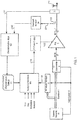
- FIG. 1 illustrates a RF PA system, according to an embodiment of the present disclosure.
- RF PA system includes a transmit modulator 10, an amplitude estimator 13, a RF up converter 2, a power amplifier (PA) 3, an antenna 4, a duplexer 5, a feedback receiver 24, a characterization block 102, characterization information tables 33, a supply control block 104 and an envelope tracking (ET) power supply 8.
- PA power amplifier
- E envelope tracking
- Each of the blocks shown in the figures can implemented in circuitry or a combination of circuitry and software.
- RF PA system may be found in a cell phone, mobile hotspot, tablet computer, or any other type of computing device that supports wireless communications.
- RF PA system can support different wireless transmission standards such as 3G, 4G and Long Term Evolution (LTE) for transmitting wireless signals to a remote device.
- LTE Long Term Evolution
- Transmit modulator 10 generates a digital baseband signal 1 that includes desired information to be transmitted as radio signals to a remote device.
- Digital baseband signal 1 is up converted by RF up converter 2 to generate a RF input signal 17 that operates at a particular RF carrier frequency.
- Variable gain RF up converter 2 may be realized by a pair of up converting mixer circuits, followed by a variable gain driver. The gain of the variable gain RF up converter 2 is controlled by the transmit modulator 10 through the gain control signal 16. The gain of the variable gain RF up converter 2 may be adjusted for a variety of reasons, including transmit power control, and noise optimization in the transmit path.
- Optional predistortion block may also predistort the baseband signal 1 before it reaches the variable gain RF up converter 2.
- the predistortion block may receive the feedback signal 42 from the feedback receiver 24 and compare this signal 42 to the baseband signal 1 to update its predistortion parameters.
- the PA 3 receives and amplifies the RF input signal 17 to generate an RF output signal 12 at the output of the PA 3.
- RF output signal 12 reaches the antenna 4 after passing through duplexer filter 5 and is transmitted wirelessly by the antenna 4 to a remote device.
- Duplexer filter 5 provides isolation between the RF output signal 12 and receive (RX) signal 11 from the antenna 4, while passing the RF output signal 12 to the antenna 4.
- the PA 3 is powered by an envelope tracking supply voltage VCC that tracks the envelope amplitude of the RF input signal 17.
- the level of the supply voltage VCC is important because it strikes a balance between PA 3 power efficiency and linearity. In general, if the supply voltage is low, the PA 3 operates with lower headroom, and thus with higher efficiency, but higher distortion. Conversely, if the supply voltage values are set higher, the PA 3 operates with higher headroom, and thus with lower efficiency, but the additional headroom allows for lower distortion levels.
- Digital baseband transmit signal 1 is also fed to the amplitude estimator 13.
- the amplitude estimator 13 determines the envelope amplitude of the RF input signal 17 and generates an input amplitude signal 110 that is indicative of the amplitude of the RF input signal 17.
- Amplitude estimator 13 then adds the gain of variable gain RF up converter 2 indicated by gain control signal 16 to this result. Since the gain of variable gain RF up converter 2 is controlled by transmit modulator 10, gain control signal 16 is also fed into amplitude estimator 13 so that amplitude estimator 13 knows the gain of the variable gain RF up converter 2.
- Supply control block 104 receives the input amplitude signal 110 and generates a supply control signal 18 that varies as the RF input amplitude indicated by the input amplitude signal 110 changes.
- the supply control block 104 takes into account different operating conditions of the RF PA system when generating the supply control signal 18. Examples of operating conditions include the ambient temperature of the RF PA system, the operating frequency of the RF PA system (e.g., RF carrier frequency), the modulation format of the baseband signal 1 (e.g., orthogonal frequency divisional multiplexing, phase-shift keying), the amount of antenna mismatch at the output of the PA 3 (e.g. output impedance mismatch) and various environmental factors.
- operating conditions include the ambient temperature of the RF PA system, the operating frequency of the RF PA system (e.g., RF carrier frequency), the modulation format of the baseband signal 1 (e.g., orthogonal frequency divisional multiplexing, phase-shift keying), the amount of antenna mismatch at the output of the PA 3 (e.g
- the supply control block 62 may generate the supply control signal 18 using a look up table that references amplitude values of the input amplitude signal 110 to supply voltage values for the supply control signal 18.
- supply control block 104 may use an equation that calculates a value for the supply control signal 18 from the input amplitude signal 110.
- the ET power supply 8 controls the level of the supply voltage VCC in accordance with the supply control signal 18.
- Examples of ET power supply 8 include linear regulators, switching power supplies, and hybrid power supplies that utilize both a linear regulator and a switching power supply.
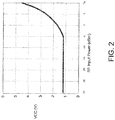
- FIG. 2 illustrated is a graph of relationship between RF input power to the PA 3 and the supply voltage VCC (which corresponds to supply control signal 18), according to an embodiment.
- the horizontal axis represents the RF input power to the PA, which corresponds to the amplitude of the RF input signal 17.
- the vertical axis represents the supply voltage VCC to the PA 3.
- the supply voltage VCC is controlled in an envelope tracking manner such that the supply voltage VCC substantially tracks the RF input power when the RF input power is greater than -5 dBm. Note that the supply voltage VCC is held substantially constant at a minimum level of 1.2 V when the RF input power is less than -5 dBm so that the PA 3 may remain biased properly.
- decoupler 22 and characterization block 102 form a feedback path for characterizing the RF PA system and generating the characterization tables 33.
- Decoupler 22 provides a coupled version 23 of the RF output signal 12 to the feedback receiver 24.
- the feedback receiver 24 then generates an output amplitude signal 42 indicative of the amplitude of the RF output signal 12.
- Characterization block 102 receives the output amplitude signal 42, the RX signal 11 and other information and uses these inputs to measure performance characteristics (e.g. gain, power efficiency, distortion, receive band noise) of the RF PA system. Examples of performance characteristics include gain, power efficiency, distortion, and receive band noise, among others.
- the performance characteristics are measured across many different RF input levels and supply voltage values for different levels (e.g., different dimensions or states) of operating conditions of the RF PA system.
- the characterization block 102 then generates one or more characterization tables 33 that include characterization information describing relationships between different RF input levels, supply voltage values, operating condition levels, RF output levels and the measured performance levels of the RF PA system.
- the characterization tables 33 can be stored in a memory, such as a non-volatile memory.
- the operating conditions in Table 1 include temperature and frequency.
- the performance characteristics in Table 1 include gain and power efficiency.
- Table 1 illustrates just a small portion of a characterization table 33.
- the characterization tables 33 may have hundreds or more of different entries spread across one or more tables that capture different combinations of RF input amplitude, supply voltage values, operating condition levels, performance characteristics, and RF output amplitude.
- characterization tables 33 may include equations which relate RF input amplitude, supply voltage values to RF output amplitude and performance characteristics under given operating conditions. The equations may compute a performance characteristic of the RF PA system from variables for different operating conditions, RF input amplitude, and supply voltage.
- the supply control block 104 uses the characterization information in the characterization tables 33 to determine values for the supply control signal 18 that balance power efficiency and distortion for current levels of one or more operating conditions (e.g. temperature, frequency, modulation, impedance mismatch) of the RF PA system. Because the characterization tables 33 are generated locally at the RF PA system during normal operation of the RF PA system, it allows the supply control block 104 to control the supply voltage VCC in a manner that more accurately balances power efficiency and distortion to adapt to actual operating conditions than would otherwise be possible.
- one or more operating conditions e.g. temperature, frequency, modulation, impedance mismatch
- a delay alignment block may also insert a time delay at ET power supply 8 or within variable gain RF up converter 2 to ensure proper time synchronization between the supply voltage VCC and the amplitude of the RF output signal 12.
- FIG. 3 illustrates a more detailed view of the RF PA system from FIG. 1 , according to an embodiment.
- Supply control block 104 includes a look up table (LUT) builder block 302, a LUT, a supply voltage adjustment block 314 and a digital to analog converter (DAC).
- the LUT references amplitude levels of the amplitude signal 110 to digital supply voltage values.
- the LUT may have 32 entries for supply voltage values, corresponding to RF input power levels of -21 dB to +10dBm spaced 1dB apart.
- the initial supply voltage values in the LUT are typically determined in a factory through characterization of a typical PA on a typical radio device under typical conditions.
- the LUT may be populated with this set of nominal supply voltage values which are appropriate for various values of expected RF output 12 signal amplitudes, based on the expected gain of the PA, under nominal conditions.
- the LUT outputs supply voltage values 312, which are adjusted by the supply voltage adjustment circuit 314 into adjusted supply voltage values 316.
- the operation of the voltage adjustment circuit 114 will be explained by greater detail below in reference to the characterization block 102.
- the adjusted supply voltage values 316 are converted into an analog supply control signal 18 with a digital to analog converter DAC.
- the supply control signal 18 controls ET power supply 8 to output specific supply voltage VCC levels for supplying PA 3 with power.
- the PA 3 may exhibit different characteristics from those during operation of the typical PA 3 in the factory, depending on factors such as PA process and manufacturing tolerances, power supply circuit variations, environmental factors, temperature, operating frequency, modulation formats, antenna mismatch to name a few. Due to these unpredictable variations in characteristics, the default LUT entries may not be well suited for operating the RF PA system at target power efficiency and distortion levels.
- the characterization block 102 characterizes the RF PA system by perturbing the system with small changes to the supply voltage VCC, so as not to cause excessive distortion in the RF PA system, while also measuring performance characteristics of the RF PA system. This process is repeated for different operating condition levels and amplitudes of the RF input signal 17 to generate the characterization tables 33.
- the LUT builder 302 uses the characterization tables 33 to change and refine the values in the LUT.
- the characterization block 102 includes a table generation block 322, a distortion estimator 324, an efficiency estimator 326 and a noise estimator 352. Characterization typically occurs while the RF PA system is operating in normal transmit operation without an offline calibration mode. In other words, characterization occurs while the transmit modulator 10 is generating a baseband signal 1 that includes information to be transmitted to a remote device. The baseband signal 1 is converted to an RF input signal 17 and amplified into a RF output signal 12. The RF input amplitude is provided to the LUT that outputs a supply voltage value 312 using the initial LUT values.
- the table generation block 322 also generates a voltage adjustment signal 318 specifying a target level of adjustment (e.g., a multiplication factor) for the supply voltage VCC.
- the supply voltage adjustment circuit 314 then adjusts the supply voltage value 312 into an adjusted supply voltage value 316 that is converted into a supply control signal 18.
- FIG. 4 illustrated are waveforms illustrating an adjustment to the supply voltage VCC during characterization, according to an embodiment.
- FIG. 4 includes a waveform for the RF output signal 12 and a waveform for the supply voltage VCC that tracks the amplitude of the RF output signal 12.
- the supply voltage VCC Prior to time T1, the supply voltage VCC is generated using the default supply voltage values 312 without any adjustment.
- the default supply voltage values 312 are adjusted by the voltage adjustment signal 318, which causes a discontinuity in the supply voltage VCC. The discontinuity is small enough so that any distortion in the RF output signal 12 still falls below the threshold of regulatory amplitude or phase error requirements.
- the supply voltage VCC continues to be generated by adjusting the default LUT values.
- the adjustment causes a slight increase in the supply voltage VCC after time T1. In other embodiments the adjustment can cause a decrease in the supply voltage VCC instead of an increase in the supply voltage VCC.
- efficiency estimator block 326 estimates the power efficiency of the PA 3 associated with the adjusted supply voltage VCC and generates a power efficiency signal 334 indicative of the estimated power efficiency.
- Mismatch may be a fixed value or a variable value empirically determined based on impedance mismatch calculated from the power ratio and phase difference between forward and reverse power detected with forward and reverse connected directional couplers (not shown) coupled to the output of PA 3.
- Pconsumed is the power consumed by the PA 3.
- Pconsumed is determined by sampling, through sampling signals 332 obtained from sampling circuit 340, the current and the voltage supplied to PA 3 and then multiplying the sampled current and the sampled voltage.
- the sampling circuit 340 since the level of the supply voltage VCC is known at any given time, the sampling circuit 340 only samples the supply current instead of the supply voltage VCC.
- Distortion estimator block 324 estimates distortion of the PA 3 associated with the adjusted supply voltage VCC and generates one or more distortion signals 336 indicative of the estimated distortion levels.
- the distortion estimator block 324 receives the baseband signal 1 that includes the desired transmit information.
- the distortion estimator block 324 compares the amplitude of the baseband signal 1 to the RF output amplitude (indicated by the output amplitude signal 42) to estimate the distortion of the PA 3. Greater differences between the desired transmit signal and the RF output amplitude indicate a higher amount of distortion.
- the distortion estimator block 324 stores samples of the RF output amplitude over time and determines AM-AM distortion (i.e. amplitude distortion) or AM-PM distortion (i.e. phase distortion) of the PA from the samples.
- AM-AM distortion is calculated as a ratio of the change in the RF output amplitude to the change in the supply voltage VCC.
- AM-PM distortion is calculated as a ratio of measured change in the RF output phase to the change in the supply voltage VCC.
- the AM-PM distortion and the AM-PM distortion should be flat.
- the distortion estimator block 324 can measure distortion in the form of adjacent-channel leakage power (ACP).
- ACP adjacent-channel leakage power
- distortion can be represented with a polynomial that accounts for memory effects of the RF PA system.
- Memory effects refer to the fact that past conditions in the RF PA system that can affect current levels of distortion in the RF PA system.
- Noise estimator block 352 receives the RX signal 11 and estimates a receive band noise 352 in the RX signal 11. Changing the supply voltage VCC 340 to the PA 3 can sometimes introduce noise into the RX signal 11. The noise estimator block estimates this noise and then generates a noise estimation signal indicative of the level of receive band noise 352.
- the table generation block 322 receives the input amplitude signal 110, output amplitude signal 42, distortion signals 336, power efficiency signal 326 and noise estimation signal 353.
- Table generation block 322 generates an entry in the characterization table 33 that relates the RF input amplitude, the supply voltage values for the adjusted supply voltage VCC, the RF output amplitude, the levels of the operating conditions, and the level of the performance characteristics (e.g. gain, power efficiency, distortion, noise). This process may be repeated many times for different RF input amplitudes, different supply voltage values, and different levels of operating conditions to generate many different table entries.
- the result is a collection of characterization information describing the relationship between RF input amplitudes, supply voltage values, RF output amplitudes, operating conditions, and performance characteristics, for example, as shown in Table 1.
- the table generation block 322 estimates the gain of the PA 3 from the input amplitude signal 110 and the output amplitude signal 42. In other embodiments the table generation block 322 may obtain amplitude information for the RF input signal directly from the LUT and use this amplitude information to estimate the gain.
- the LUT builder 302 then utilizes the characterization tables 33 to generate a new set of supply voltage values 312 for the LUT according to the current operating conditions (e.g., temperature, frequency, modulation, mismatch) currently present in the system.
- the LUT builder 302 may receive signals indicating that current operating conditions are a temperature of 25 degrees C, a carrier frequency of 1700 MHz, a modulation type of PSK and zero impedance mismatch.
- the LUT builder 302 then generates supply voltage values 312 for this set of current operating conditions.
- the LUT builder block 302 may generate a more complex LUT that uses one or more operating conditions as an input to the LUT.
- the supply voltage values 312 may be interpolated or extrapolated from information in the characterization tables 33. Alternatively, the equations in characterization tables 33 may be utilized to generate the new supply voltage values 312 for the LUT.
- the LUT builder 302 generates a LUT that keeps the RF PA system operating in a range of target performance levels under the current operating conditions.
- the LUT can be generated such that the PA 3 produces distortion within an acceptable target range and also has power efficiency within an acceptable target range.
- the LUT builder 302 may also generate the LUT that keeps the RF PA system operating at a specific target performance level.
- the LUT can be generated such that the PA 3 has constant gain.
- the LUT can be generated such that the PA 3 has constant AM-AM distortion.
- FIG. 5 illustrates a method of operation in a RF PA system, according to an embodiment.
- the LUT is populated with an initial set of supply voltage values 312.
- the initial values are typically generic values that are appropriate for a typical radio device under typical operating conditions.
- the RF PA system operates in normal transmit operation by generating a baseband signal 1 with desired transmit information that is transmitted to a remote device through the antenna 4.
- the RF PA system also uses the initial set of supply voltage values 312 in controlling the supply voltage VCC.
- the characterization block 102 characterizes the RF PA system without interrupting the operation of the RF PA system.
- the characterization block 102 adjusts the supply voltage value 312 in order to adjust the supply voltage VCC.
- the characterization block 102 assesses the resulting performance (e.g. power efficiency, distortion and receive band noise) associated with the adjusted supply voltage VCC.
- the characterization block 102 then generates new entries for the characterization table 33.
- step 508 once characterization is completed, the supply control block 104 uses the characterization table 33 to generate new supply voltage values 312 for the LUT.
- step 510 during a later period in time, the new supply voltage values 312 for the LUT are then used to control the supply voltage control signal 18 and therefore also the supply voltage VCC. Steps 506, 508 and 510 may also be repeated at periodic intervals to capture any changes in the characteristics of the RF PA system that may occur over time and to further refine the LUT.
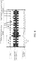
- FIG. 6 illustrates adjustments to the supply voltage VCC during characterization, according to another embodiment.
- FIG. 6 includes waveforms for the supply voltage VCC, the amplitude of the RF input signal 17, and the supply current to the PA 3.
- the baseband signal 1 is generated with a randomized (i.e. random or pseudorandom) pattern, which causes the amplitude of the RF input signal 17 to also have the same randomized pattern.
- the randomized pattern of the baseband signal 1 causes the amplitude of the RF input signal 17 to alternate between reset positions having fixed amplitude and randomized positions having random amplitude.
- the supply voltage VCC has a different randomized pattern.
- the randomized pattern of the supply voltage VCC also alternates between reset positions having fixed voltage levels and randomized positions having random voltage levels.
- Each new amplitude of the RF input signal 17 corresponds to a different level of the supply voltage VCC.
- the randomized patterns speed up the building of the characterization tables 33 and may be generated in a dedicated offline characterization mode.
- characterization block 102 estimates power efficiency and distortion levels for different RF input amplitudes and supply voltage VCC levels to generate new entries for the characterization table 33.
Claims (13)
- Hochfrequenz (HF)- Leistungsverstärkersystem, umfassend:einen Leistungsverstärker (3), der dafür ausgebildet ist,ein HF-Ausgangssignal (12) aus einem HF-Eingangssignal (17) zu generieren, wobei der Leistungsverstärker (3) durch eine Versorgungsspannung (VCC) betrieben wird,einen Charakterisierungsblock (102), der dafür ausgebildet ist, ein Anpassungssignal zum Anpassen der Versorgungsspannung (VCC) in einem ersten Zeitraum zu generieren, in dem das HF-Leistungsverstärkersystem im normalen Sendebetrieb arbeitet, und Charakterisierungsinformationen zu generieren, wenn die Versorgungsspannung (VCC) während des ersten Zeitraums angepasst wird, ohne den Betrieb des HF-Leistungsverstärkersystems zu unterbrechen, wobei die Charakterisierungsinformationen einer Beziehung zwischen der Versorgungsspannung (VCC) und der Leistung des HF-Leistungsverstärkersystems für mehrere Ebenen von einem oder mehreren Betriebszuständen des HF-Leistungsverstärkersystems entsprechen,einen Amplitudenschätzerblock (13), der dafür ausgebildet ist, eine Amplitude (110) des HF-Eingangssignals (17) zu schätzen, undeinen Versorgungssteuerungsblock (104), der dafür ausgebildet ist, ein Versorgungsspannungssteuersignal (18) zum Steuern der Versorgungsspannung (VCC) zu dem PA (3) auf der Basis anfänglicher Versorgungsspannungswerte in einer Nachschlagetabelle (LUT) und der Amplitude des HF-Eingangssignals (17) während des ersten Zeitraums zu generieren und das Versorgungsspannungssteuersignal (18) auf der Basis der generierten Charakterisierungsinformationen und der Amplitude (110) des HF-Eingangssignals (17) in einem zweiten Zeitraum zu generieren, wenn der Charakterisierungsblock (102) das Generieren der Charakterisierungsinformationen vollendet hat.
- HF-Leistungsverstärkersystem nach Anspruch 1, des Weiteren umfassend:einen Rückkopplungsblock (24), der dafür ausgebildet ist,eine Amplitude (42) des HF-Ausgangssignals (12) zu schätzen, wobei der Charakterisierungsblock (102) dafür ausgebildet ist, die Charakterisierungsinformationen auf der Basis der Amplitude (42) des HF-Ausgangssignals (12) zu generieren.
- HF-Leistungsverstärkersystem nach einem der Ansprüche 1 und 2, wobei der Charakterisierungsblock (102) die Leistung des HF-Leistungsverstärkersystems über mehrere Ebenen der Versorgungsspannung (VCC) hinweg schätzt und die Charakterisierungsinformationen auf der Basis der geschätzten Leistung des HF-Leistungsverstärkersystems generiert.
- HF-Leistungsverstärkersystem nach einem der Ansprüche 1 und 2, wobei
der Charakterisierungsblock (102) die Charakterisierungsinformationen während des normalen Sendebetriebes des HF-Leistungsverstärkersystems generiert, oder
der Charakterisierungsblock (102) die Charakterisierungsinformationen generiert, während die Versorgungsspannung (VCC) und das HF-Eingangssignal (17) mit randomisierten Mustern bereitgestellt werden. - HF-Leistungsverstärkersystem nach einem der Ansprüche 1 bis 4, wobei der Versorgungssteuerungsblock (104) die Nachschlagetabelle (LUT) auf der Basis der Charakterisierungsinformationen generiert und das Versorgungsspannungssteuersignal (18) auf der Basis von Werten in der Nachschlagetabelle (LUT), die der Amplitude (110) des HF-Eingangssignals (17) entsprechen, generiert.
- HF-Leistungsverstärkersystem nach einem der Ansprüche 1 bis 4, wobei der Versorgungssteuerungsblock (104) das Versorgungsspannungssteuersignal (18) auf der Basis einer momentanen Ebene des Betriebszustands des HF-Leistungsverstärkersystems generiert.
- HF-Leistungsverstärkersystem nach einem der Ansprüche 1 bis 6, wobei die Charakterisierungsinformationen mindestens einem von Folgendem entsprechen:einer Beziehung zwischen der Versorgungsspannung (VCC) und einer Verstärkung des Leistungsverstärkers (3) für mehrere Ebenen von einem oder mehreren Betriebszuständen des HF-Leistungsverstärkersystems,einer Beziehung zwischen der Versorgungsspannung (VCC) und einer Leistungseffizienz des HF-Leistungsverstärkersystems für mehrere Ebenen von einem oder mehreren Betriebszuständen des HF-Leistungsverstärkersystems,einer Beziehung zwischen der Versorgungsspannung (VCC) und einer Verzerrung des HF-Leistungsverstärkersystems für mehrere Ebenen von einem oder mehreren Betriebszuständen des HF-Leistungsverstärkersystems, undeiner Beziehung zwischen der Versorgungsspannung (VCC) und einem Empfangsbandrauschen in dem HF-Leistungsverstärkersystem für mehrere Ebenen von einem oder mehreren Betriebszuständen des HF-Leistungsverstärkersystems.
- HF-Leistungsverstärkersystem nach einem der Ansprüche 1 bis 7, wobei die Betriebszustände des HF-Leistungsverstärkersystems mindestens eines von Temperatur, Betriebsfrequenz, Modulationsformat und Antennennichtübereinstimmung umfassen.
- Verfahren zum Betrieb in einem Hochfrequenz (HF)-Leistungsverstärkersystem, wobei das Verfahren Folgendes umfasst:Generieren, durch einen Leistungsverstärker (3), eines HF-Ausgangssignals (12) auf der Basis eines HF-Eingangssignales (17),Generieren eines Anpassungssignals zum Anpassen einer Versorgungsspannung (VCC) zu dem Leistungsverstärker (3) in einem ersten Zeitraum, in dem das HF-Leistungsverstärkersystem im normalen Sendebetrieb arbeitet,Generieren von Charakterisierungsinformationen, wenn die Versorgungsspannung (VCC) in dem ersten Zeitraum angepasst wird, ohne den Betrieb des HF-Leistungsverstärkersystems zu unterbrechen, wobei die Charakterisierungsinformationen einer Beziehung zwischen der Versorgungsspannung (VCC) zu dem Leistungsverstärker (3) und einer Leistung des Leistungsverstärkers (3) für mehrere Ebenen eines Betriebszustands des HF-Leistungsverstärkersystems entsprechen,Schätzen einer Amplitude (110) des HF-Eingangssignals (17),Generieren eines Versorgungsspannungssteuersignals (18) zum Steuern der Versorgungsspannung (VCC) zu dem Leistungsverstärker (3) auf der Basis der anfänglichen Versorgungsspannungswerte in einer Nachschlagetabelle (LUT) und der Amplitude (110) des HF-Eingangssignals (17) in dem ersten Zeitraum, undGenerieren des Versorgungsspannungssteuersignals (18) zum Steuern der Versorgungsspannung (VCC) zu dem Leistungsverstärker (3) auf der Basis der generierten Charakterisierungsinformationen und der Amplitude (110) des HF-Eingangssignals (17) in einem zweiten Zeitraum, wenn das Generieren der Charakterisierungsinformationen vollendet ist.
- Verfahren nach Anspruch 9, das des Weiteren das Schätzen einer Amplitude (42) des HF-Ausgangssignals (12) enthält, wobei die Charakterisierungsinformationen auf der Basis der Amplitude (42) des HF-Ausgangssignals (12) generiert werden.
- Verfahren nach Anspruch 9, das des Weiteren das Schätzen der Leistung des HF-Leistungsverstärkersystems über mehrere Ebenen der Versorgungsspannung (VCC) hinweg enthält, wobei die Charakterisierungsinformationen auf der Basis einer geschätzten Leistung des HF-Leistungsverstärkersystems generiert werden.
- Verfahren nach Anspruch 9, wobei die Charakterisierungsinformationen während des normalen Sendebetriebes des HF-Leistungsverstärkersystems generiert werden, oder während die Versorgungsspannung (VCC) und das HF-Eingangssignal (17) mit randomisierten Mustern bereitgestellt werden.
- Verfahren nach einem der Ansprüche 9 bis 12, wobei das Generieren des Versorgungssteuersignals (18) das Generieren der Nachschlagetabelle (LUT) auf der Basis der Charakterisierungsinformationen und das Generieren des Versorgungsspannungssteuersignals (18) auf der Basis von Werten in der Nachschlagetabelle (LUT), die der Amplitude (110) des HF-Eingangssignals (17). entsprechen, enthält.
Applications Claiming Priority (2)
| Application Number | Priority Date | Filing Date | Title |
|---|---|---|---|
| US201361800350P | 2013-03-15 | 2013-03-15 | |
| PCT/US2014/026431 WO2014151777A1 (en) | 2013-03-15 | 2014-03-13 | Envelope tracking system with internal power amplifier characterization |
Publications (3)
| Publication Number | Publication Date |
|---|---|
| EP2974006A1 EP2974006A1 (de) | 2016-01-20 |
| EP2974006A4 EP2974006A4 (de) | 2016-07-13 |
| EP2974006B1 true EP2974006B1 (de) | 2017-10-25 |
Family
ID=51524897
Family Applications (1)
| Application Number | Title | Priority Date | Filing Date |
|---|---|---|---|
| EP14767467.5A Active EP2974006B1 (de) | 2013-03-15 | 2014-03-13 | Hüllkurvennachführungssystem mit interner leistungsverstärkercharakterisierung |
Country Status (8)
| Country | Link |
|---|---|
| US (2) | US9270239B2 (de) |
| EP (1) | EP2974006B1 (de) |
| JP (1) | JP6166457B2 (de) |
| KR (1) | KR102174242B1 (de) |
| CN (1) | CN105103443B (de) |
| HK (1) | HK1213372A1 (de) |
| TW (1) | TWI540829B (de) |
| WO (1) | WO2014151777A1 (de) |
Families Citing this family (56)
| Publication number | Priority date | Publication date | Assignee | Title |
|---|---|---|---|---|
| WO2013134026A2 (en) | 2012-03-04 | 2013-09-12 | Quantance, Inc. | Envelope tracking power amplifier system with delay calibration |
| US9042848B2 (en) * | 2012-12-19 | 2015-05-26 | Mediatek Singapore Pte. Ltd. | Method and apparatus for calibrating an envelope tracking system |
| US9271236B2 (en) | 2013-03-14 | 2016-02-23 | Quantance, Inc. | ET system with adjustment for noise |
| WO2014151777A1 (en) | 2013-03-15 | 2014-09-25 | Quantance, Inc. | Envelope tracking system with internal power amplifier characterization |
| US9231627B2 (en) * | 2013-11-06 | 2016-01-05 | Stmicroelectronics International N.V. | Adaptive ISO-Gain pre-distortion for an RF power amplifier operating in envelope tracking |
| DE102014105909A1 (de) * | 2014-04-28 | 2015-10-29 | Phoenix Contact Gmbh & Co. Kg | Energieversorgungsgerät |
| US10333474B2 (en) * | 2014-05-19 | 2019-06-25 | Skyworks Solutions, Inc. | RF transceiver front end module with improved linearity |
| US9998241B2 (en) | 2015-02-19 | 2018-06-12 | Mediatek Inc. | Envelope tracking (ET) closed-loop on-the-fly calibration |
| DE102015110238A1 (de) * | 2015-06-25 | 2016-12-29 | Intel IP Corporation | Eine Schaltung und ein Verfahren zum Erzeugen eines Radiofrequenzsignals |
| WO2017019803A1 (en) * | 2015-07-28 | 2017-02-02 | Skyworks Solutions, Inc. | Power amplification system with programmable load line |
| US11201595B2 (en) * | 2015-11-24 | 2021-12-14 | Skyworks Solutions, Inc. | Cascode power amplifier with switchable output matching network |
| KR102594658B1 (ko) * | 2016-12-23 | 2023-10-26 | 삼성전자주식회사 | 무선 송신을 제어하는 장치 및 방법 |
| US10181826B2 (en) | 2017-04-25 | 2019-01-15 | Qorvo Us, Inc. | Envelope tracking amplifier circuit |
| US10158330B1 (en) | 2017-07-17 | 2018-12-18 | Qorvo Us, Inc. | Multi-mode envelope tracking amplifier circuit |
| US10284412B2 (en) | 2017-07-17 | 2019-05-07 | Qorvo Us, Inc. | Voltage memory digital pre-distortion circuit |
| CN109286375B (zh) * | 2017-07-19 | 2021-03-02 | 陕西亚成微电子股份有限公司 | 一种用于包络跟踪的电源 |
| US10326490B2 (en) | 2017-08-31 | 2019-06-18 | Qorvo Us, Inc. | Multi radio access technology power management circuit |
| US10680559B2 (en) * | 2017-10-06 | 2020-06-09 | Qorvo Us, Inc. | Envelope tracking system for transmitting a wide modulation bandwidth signal(s) |
| US10439557B2 (en) | 2018-01-15 | 2019-10-08 | Qorvo Us, Inc. | Envelope tracking power management circuit |
| US10637408B2 (en) | 2018-01-18 | 2020-04-28 | Qorvo Us, Inc. | Envelope tracking voltage tracker circuit and related power management circuit |
| US10742170B2 (en) | 2018-02-01 | 2020-08-11 | Qorvo Us, Inc. | Envelope tracking circuit and related power amplifier system |
| US10944365B2 (en) | 2018-06-28 | 2021-03-09 | Qorvo Us, Inc. | Envelope tracking amplifier circuit |
| US11088618B2 (en) | 2018-09-05 | 2021-08-10 | Qorvo Us, Inc. | PWM DC-DC converter with linear voltage regulator for DC assist |
| US10911001B2 (en) | 2018-10-02 | 2021-02-02 | Qorvo Us, Inc. | Envelope tracking amplifier circuit |
| KR102226814B1 (ko) * | 2018-10-26 | 2021-03-11 | 삼성전자 주식회사 | 스위칭 레귤레이터를 이용하여 복수의 증폭기들에 선택적으로 전압을 공급하는 방법 및 장치 |
| US10985702B2 (en) | 2018-10-31 | 2021-04-20 | Qorvo Us, Inc. | Envelope tracking system |
| US11018638B2 (en) | 2018-10-31 | 2021-05-25 | Qorvo Us, Inc. | Multimode envelope tracking circuit and related apparatus |
| US10938351B2 (en) | 2018-10-31 | 2021-03-02 | Qorvo Us, Inc. | Envelope tracking system |
| US10680556B2 (en) | 2018-11-05 | 2020-06-09 | Qorvo Us, Inc. | Radio frequency front-end circuit |
| US11031909B2 (en) | 2018-12-04 | 2021-06-08 | Qorvo Us, Inc. | Group delay optimization circuit and related apparatus |
| US11082007B2 (en) | 2018-12-19 | 2021-08-03 | Qorvo Us, Inc. | Envelope tracking integrated circuit and related apparatus |
| JP2020107970A (ja) * | 2018-12-26 | 2020-07-09 | 株式会社村田製作所 | 電源回路 |
| US11146213B2 (en) | 2019-01-15 | 2021-10-12 | Qorvo Us, Inc. | Multi-radio access technology envelope tracking amplifier apparatus |
| US10998859B2 (en) | 2019-02-07 | 2021-05-04 | Qorvo Us, Inc. | Dual-input envelope tracking integrated circuit and related apparatus |
| US11025458B2 (en) | 2019-02-07 | 2021-06-01 | Qorvo Us, Inc. | Adaptive frequency equalizer for wide modulation bandwidth envelope tracking |
| US11233481B2 (en) | 2019-02-18 | 2022-01-25 | Qorvo Us, Inc. | Modulated power apparatus |
| US11374482B2 (en) | 2019-04-02 | 2022-06-28 | Qorvo Us, Inc. | Dual-modulation power management circuit |
| US11082009B2 (en) | 2019-04-12 | 2021-08-03 | Qorvo Us, Inc. | Envelope tracking power amplifier apparatus |
| US11018627B2 (en) | 2019-04-17 | 2021-05-25 | Qorvo Us, Inc. | Multi-bandwidth envelope tracking integrated circuit and related apparatus |
| US11424719B2 (en) | 2019-04-18 | 2022-08-23 | Qorvo Us, Inc. | Multi-bandwidth envelope tracking integrated circuit |
| US11031911B2 (en) | 2019-05-02 | 2021-06-08 | Qorvo Us, Inc. | Envelope tracking integrated circuit and related apparatus |
| US11349436B2 (en) | 2019-05-30 | 2022-05-31 | Qorvo Us, Inc. | Envelope tracking integrated circuit |
| US11539289B2 (en) | 2019-08-02 | 2022-12-27 | Qorvo Us, Inc. | Multi-level charge pump circuit |
| US11309922B2 (en) | 2019-12-13 | 2022-04-19 | Qorvo Us, Inc. | Multi-mode power management integrated circuit in a small formfactor wireless apparatus |
| US11349513B2 (en) | 2019-12-20 | 2022-05-31 | Qorvo Us, Inc. | Envelope tracking system |
| US11539330B2 (en) | 2020-01-17 | 2022-12-27 | Qorvo Us, Inc. | Envelope tracking integrated circuit supporting multiple types of power amplifiers |
| US11716057B2 (en) | 2020-01-28 | 2023-08-01 | Qorvo Us, Inc. | Envelope tracking circuitry |
| US11728774B2 (en) | 2020-02-26 | 2023-08-15 | Qorvo Us, Inc. | Average power tracking power management integrated circuit |
| JP2021153248A (ja) * | 2020-03-24 | 2021-09-30 | 株式会社村田製作所 | パワーアンプ評価方法及び測定システム |
| US11196392B2 (en) | 2020-03-30 | 2021-12-07 | Qorvo Us, Inc. | Device and device protection system |
| US20220052648A1 (en) * | 2020-08-12 | 2022-02-17 | Qorvo Us, Inc. | Systems and methods for providing an envelope tracking supply voltage |
| US11923812B2 (en) | 2020-08-12 | 2024-03-05 | Qorvo Us, Inc. | Delay-compensating power management integrated circuit |
| US11929712B2 (en) | 2020-08-12 | 2024-03-12 | Qorvo Us, Inc. | Delay-compensating power management circuit |
| US11588449B2 (en) | 2020-09-25 | 2023-02-21 | Qorvo Us, Inc. | Envelope tracking power amplifier apparatus |
| US11728796B2 (en) | 2020-10-14 | 2023-08-15 | Qorvo Us, Inc. | Inverted group delay circuit |
| US11909385B2 (en) | 2020-10-19 | 2024-02-20 | Qorvo Us, Inc. | Fast-switching power management circuit and related apparatus |
Family Cites Families (53)
| Publication number | Priority date | Publication date | Assignee | Title |
|---|---|---|---|---|
| JPH0644716B2 (ja) * | 1984-08-14 | 1994-06-08 | 日本電気株式会社 | 無線通信装置 |
| US6084468A (en) | 1997-10-06 | 2000-07-04 | Motorola, Inc. | Method and apparatus for high efficiency wideband power amplification |
| US6130910A (en) | 1997-11-03 | 2000-10-10 | Motorola, Inc. | Method and apparatus for high efficiency wideband power amplification |
| US6356146B1 (en) | 1999-07-13 | 2002-03-12 | Pmc-Sierra, Inc. | Amplifier measurement and modeling processes for use in generating predistortion parameters |
| GB2370435A (en) | 2000-12-22 | 2002-06-26 | Nokia Mobile Phones Ltd | A polar loop transmitter for a mobile phone |
| AUPR438601A0 (en) | 2001-04-11 | 2001-05-17 | Cochlear Limited | Variable sensitivity control for a cochlear implant |
| US6683496B2 (en) * | 2001-08-20 | 2004-01-27 | Harris Corporation | System and method for minimizing dissipation in RF power amplifiers |
| US6784744B2 (en) | 2001-09-27 | 2004-08-31 | Powerq Technologies, Inc. | Amplifier circuits and methods |
| US7551688B2 (en) | 2002-04-18 | 2009-06-23 | Nokia Corporation | Waveforms for envelope tracking transmitter |
| US6646501B1 (en) * | 2002-06-25 | 2003-11-11 | Nortel Networks Limited | Power amplifier configuration |
| US7263135B2 (en) | 2002-10-03 | 2007-08-28 | Matsushita Electric Industrial Co., Ltd. | Transmitting method and transmitter apparatus |
| CN100581052C (zh) * | 2004-08-13 | 2010-01-13 | 深圳赛意法微电子有限公司 | 具有自适应的爬升和衰减时间的自动增益控制系统 |
| US7190221B2 (en) * | 2004-10-22 | 2007-03-13 | Nokia Corporation | Method and apparatus for maintaining constant linearity for a power amplifier over varying load conditions |
| US7348842B2 (en) | 2005-01-19 | 2008-03-25 | Micro-Mobio | Multi-substrate RF module for wireless communication devices |
| US20070066224A1 (en) * | 2005-02-28 | 2007-03-22 | Sirit, Inc. | High efficiency RF amplifier and envelope modulator |
| US20060199553A1 (en) | 2005-03-07 | 2006-09-07 | Andrew Corporation | Integrated transceiver with envelope tracking |
| US7418032B2 (en) | 2005-03-15 | 2008-08-26 | International Business Machines Corporation | Altering power consumption in communication links based on measured noise |
| GB2440485B (en) | 2005-04-27 | 2009-06-03 | Paragon Comm Ltd | Transformer-capacitor enhancement circuitry for power amplifiers |
| US7761066B2 (en) | 2006-01-27 | 2010-07-20 | Marvell World Trade Ltd. | Variable power adaptive transmitter |
| US8032097B2 (en) | 2006-02-03 | 2011-10-04 | Quantance, Inc. | Amplitude error de-glitching circuit and method of operating |
| US7522676B2 (en) | 2006-02-06 | 2009-04-21 | Nokia Corporation | Method and system for transmitter envelope delay calibration |
| JP2008283678A (ja) | 2007-04-11 | 2008-11-20 | Panasonic Corp | 送信回路、及び通信機器 |
| US7466195B2 (en) | 2007-05-18 | 2008-12-16 | Quantance, Inc. | Error driven RF power amplifier control with increased efficiency |
| US20090004981A1 (en) | 2007-06-27 | 2009-01-01 | Texas Instruments Incorporated | High efficiency digital transmitter incorporating switching power supply and linear power amplifier |
| US8463189B2 (en) * | 2007-07-31 | 2013-06-11 | Texas Instruments Incorporated | Predistortion calibration and built in self testing of a radio frequency power amplifier using subharmonic mixing |
| US7783269B2 (en) * | 2007-09-20 | 2010-08-24 | Quantance, Inc. | Power amplifier controller with polar transmitter |
| US8014735B2 (en) * | 2007-11-06 | 2011-09-06 | Quantance, Inc. | RF power amplifier controlled by estimated distortion level of output signal of power amplifier |
| GB0725110D0 (en) | 2007-12-21 | 2008-01-30 | Wolfson Microelectronics Plc | Gain control based on noise level |
| US8620233B2 (en) | 2008-04-11 | 2013-12-31 | Samsung Electroncs Co., Ltd. | Method of power amplifier predistortion adaptation using compression detection |
| US8072205B1 (en) | 2008-04-29 | 2011-12-06 | Analog Devices, Inc. | Peak-to-average measurement with envelope pre-detection |
| US7782134B2 (en) * | 2008-09-09 | 2010-08-24 | Quantance, Inc. | RF power amplifier system with impedance modulation |
| US8018277B2 (en) * | 2008-09-09 | 2011-09-13 | Quantance, Inc. | RF power amplifier system with impedance modulation |
| US8331883B2 (en) | 2008-10-30 | 2012-12-11 | Apple Inc. | Electronic devices with calibrated radio frequency communications circuitry |
| US8064852B2 (en) * | 2008-11-13 | 2011-11-22 | Panasonic Corporation | Methods and apparatus for dynamically compensating for DC offset drift and other PVT-related signal variations in polar transmitters |
| US9088260B2 (en) | 2008-12-03 | 2015-07-21 | Freescale Semiconductor, Inc. | Operating parameter control for a power amplifier |
| US8744009B2 (en) | 2009-09-25 | 2014-06-03 | General Dynamics C4 Systems, Inc. | Reducing transmitter-to-receiver non-linear distortion at a transmitter prior to estimating and cancelling known non-linear distortion at a receiver |
| US8731496B2 (en) * | 2009-12-18 | 2014-05-20 | Quantance, Inc. | Power amplifier power controller |
| US8183917B2 (en) * | 2010-06-04 | 2012-05-22 | Quantance, Inc. | RF power amplifier circuit with mismatch tolerance |
| JP5996559B2 (ja) | 2011-02-07 | 2016-09-21 | スカイワークス ソリューションズ,インコーポレイテッドSkyworks Solutions,Inc. | 包絡線トラッキング較正のための装置および方法 |
| GB2489002A (en) | 2011-03-14 | 2012-09-19 | Nujira Ltd | Delay adjustment to reduce distortion in an envelope tracking transmitter |
| GB2489497A (en) * | 2011-03-31 | 2012-10-03 | Nujira Ltd | Matching the properties of the envelope path to the properties of the main signal path in an envelope tracking amplifier |
| US8718188B2 (en) | 2011-04-25 | 2014-05-06 | Skyworks Solutions, Inc. | Apparatus and methods for envelope tracking |
| US9066368B2 (en) | 2011-06-08 | 2015-06-23 | Broadcom Corporation | Method of calibrating the delay of an envelope tracking signal |
| US9083453B2 (en) | 2011-06-23 | 2015-07-14 | Qualcomm Incorporated | Power supply generator with noise cancellation |
| US8754706B2 (en) | 2011-08-02 | 2014-06-17 | Qualcomm Incorporated | Power based feedback for improved power amplifier (PA) efficiency |
| US20130076418A1 (en) | 2011-09-27 | 2013-03-28 | Intel Mobile Communications GmbH | System and Method for Calibration of Timing Mismatch for Envelope Tracking Transmit Systems |
| US8880012B2 (en) | 2012-01-19 | 2014-11-04 | Motorola Mobility Llc | Method and apparatus for resource block based transmitter optimization in wireless communication devices |
| JP5624569B2 (ja) * | 2012-02-17 | 2014-11-12 | 株式会社東芝 | 電力増幅装置 |
| WO2013134026A2 (en) | 2012-03-04 | 2013-09-12 | Quantance, Inc. | Envelope tracking power amplifier system with delay calibration |
| US20140241462A1 (en) | 2013-02-26 | 2014-08-28 | Nvidia Corporation | Circuit and method for envelope tracking and envelope-tracking transmitter for radio-frequency transmission |
| US9271236B2 (en) | 2013-03-14 | 2016-02-23 | Quantance, Inc. | ET system with adjustment for noise |
| WO2014151777A1 (en) | 2013-03-15 | 2014-09-25 | Quantance, Inc. | Envelope tracking system with internal power amplifier characterization |
| GB2519361B (en) | 2013-10-21 | 2015-09-16 | Nujira Ltd | Reduced bandwidth of signal in an envelope path for envelope tracking system |
-
2014
- 2014-03-13 WO PCT/US2014/026431 patent/WO2014151777A1/en active Application Filing
- 2014-03-13 JP JP2016502142A patent/JP6166457B2/ja active Active
- 2014-03-13 KR KR1020157024837A patent/KR102174242B1/ko active IP Right Grant
- 2014-03-13 EP EP14767467.5A patent/EP2974006B1/de active Active
- 2014-03-13 CN CN201480011165.7A patent/CN105103443B/zh active Active
- 2014-03-13 US US14/208,528 patent/US9270239B2/en active Active
- 2014-03-14 TW TW103109774A patent/TWI540829B/zh active
-
2016
- 2016-02-04 US US15/015,195 patent/US9762184B2/en active Active
- 2016-02-05 HK HK16101368.4A patent/HK1213372A1/zh unknown
Non-Patent Citations (1)
| Title |
|---|
| None * |
Also Published As
| Publication number | Publication date |
|---|---|
| KR102174242B1 (ko) | 2020-11-04 |
| KR20150129731A (ko) | 2015-11-20 |
| US20140266423A1 (en) | 2014-09-18 |
| JP2016512414A (ja) | 2016-04-25 |
| EP2974006A4 (de) | 2016-07-13 |
| HK1213372A1 (zh) | 2016-06-30 |
| US9270239B2 (en) | 2016-02-23 |
| WO2014151777A1 (en) | 2014-09-25 |
| CN105103443B (zh) | 2018-01-02 |
| EP2974006A1 (de) | 2016-01-20 |
| TWI540829B (zh) | 2016-07-01 |
| CN105103443A (zh) | 2015-11-25 |
| US9762184B2 (en) | 2017-09-12 |
| TW201445874A (zh) | 2014-12-01 |
| JP6166457B2 (ja) | 2017-07-19 |
| US20160156316A1 (en) | 2016-06-02 |
Similar Documents
| Publication | Publication Date | Title |
|---|---|---|
| EP2974006B1 (de) | Hüllkurvennachführungssystem mit interner leistungsverstärkercharakterisierung | |
| JP6247787B1 (ja) | 雑音調整を有するetシステム | |
| US7741903B2 (en) | Distortion-driven power amplifier power supply controller | |
| CN107093987B (zh) | 包络跟踪系统及相关的移动通信设备和存储介质 | |
| KR101482471B1 (ko) | 부정합에 대한 내성을 가진 rf 파워 증폭기 회로 | |
| US9042848B2 (en) | Method and apparatus for calibrating an envelope tracking system | |
| US8014735B2 (en) | RF power amplifier controlled by estimated distortion level of output signal of power amplifier | |
| US9094067B2 (en) | Method and apparatus for calibrating an envelope tracking system | |
| US20110268216A1 (en) | Transmitter Gain Control and Calibration | |
| US8841967B2 (en) | Noise optimized envelope tracking system for power amplifiers |
Legal Events
| Date | Code | Title | Description |
|---|---|---|---|
| PUAI | Public reference made under article 153(3) epc to a published international application that has entered the european phase |
Free format text: ORIGINAL CODE: 0009012 |
|
| 17P | Request for examination filed |
Effective date: 20151008 |
|
| AK | Designated contracting states |
Kind code of ref document: A1 Designated state(s): AL AT BE BG CH CY CZ DE DK EE ES FI FR GB GR HR HU IE IS IT LI LT LU LV MC MK MT NL NO PL PT RO RS SE SI SK SM TR |
|
| AX | Request for extension of the european patent |
Extension state: BA ME |
|
| RIN1 | Information on inventor provided before grant (corrected) |
Inventor name: DROGI, SERGE, FRANCOIS Inventor name: VINAYAK, VIKAS |
|
| RIC1 | Information provided on ipc code assigned before grant |
Ipc: H03F 3/24 20060101ALI20160224BHEP Ipc: H03F 3/189 20060101ALI20160224BHEP Ipc: H03F 3/04 20060101AFI20160224BHEP Ipc: H03F 1/02 20060101ALI20160224BHEP Ipc: H03F 1/32 20060101ALI20160224BHEP |
|
| RIN1 | Information on inventor provided before grant (corrected) |
Inventor name: VINAYAK, VIKAS Inventor name: DROGI, SERGE, FRANCOIS |
|
| DAX | Request for extension of the european patent (deleted) | ||
| A4 | Supplementary search report drawn up and despatched |
Effective date: 20160613 |
|
| RIC1 | Information provided on ipc code assigned before grant |
Ipc: H03F 1/32 20060101ALI20160607BHEP Ipc: H03F 3/04 20060101AFI20160607BHEP Ipc: H03F 3/21 20060101ALI20160607BHEP Ipc: H03F 3/24 20060101ALI20160607BHEP Ipc: H03F 3/189 20060101ALI20160607BHEP Ipc: H03F 1/02 20060101ALI20160607BHEP Ipc: H03F 3/19 20060101ALI20160607BHEP |
|
| STAA | Information on the status of an ep patent application or granted ep patent |
Free format text: STATUS: EXAMINATION IS IN PROGRESS |
|
| 17Q | First examination report despatched |
Effective date: 20170214 |
|
| GRAP | Despatch of communication of intention to grant a patent |
Free format text: ORIGINAL CODE: EPIDOSNIGR1 |
|
| STAA | Information on the status of an ep patent application or granted ep patent |
Free format text: STATUS: GRANT OF PATENT IS INTENDED |
|
| INTG | Intention to grant announced |
Effective date: 20170612 |
|
| GRAS | Grant fee paid |
Free format text: ORIGINAL CODE: EPIDOSNIGR3 |
|
| GRAA | (expected) grant |
Free format text: ORIGINAL CODE: 0009210 |
|
| STAA | Information on the status of an ep patent application or granted ep patent |
Free format text: STATUS: THE PATENT HAS BEEN GRANTED |
|
| AK | Designated contracting states |
Kind code of ref document: B1 Designated state(s): AL AT BE BG CH CY CZ DE DK EE ES FI FR GB GR HR HU IE IS IT LI LT LU LV MC MK MT NL NO PL PT RO RS SE SI SK SM TR |
|
| REG | Reference to a national code |
Ref country code: GB Ref legal event code: FG4D |
|
| REG | Reference to a national code |
Ref country code: CH Ref legal event code: EP |
|
| REG | Reference to a national code |
Ref country code: AT Ref legal event code: REF Ref document number: 940788 Country of ref document: AT Kind code of ref document: T Effective date: 20171115 |
|
| REG | Reference to a national code |
Ref country code: IE Ref legal event code: FG4D |
|
| REG | Reference to a national code |
Ref country code: DE Ref legal event code: R096 Ref document number: 602014016334 Country of ref document: DE |
|
| REG | Reference to a national code |
Ref country code: NL Ref legal event code: MP Effective date: 20171025 |
|
| REG | Reference to a national code |
Ref country code: LT Ref legal event code: MG4D |
|
| REG | Reference to a national code |
Ref country code: AT Ref legal event code: MK05 Ref document number: 940788 Country of ref document: AT Kind code of ref document: T Effective date: 20171025 |
|
| REG | Reference to a national code |
Ref country code: FR Ref legal event code: PLFP Year of fee payment: 5 |
|
| PG25 | Lapsed in a contracting state [announced via postgrant information from national office to epo] |
Ref country code: NL Free format text: LAPSE BECAUSE OF FAILURE TO SUBMIT A TRANSLATION OF THE DESCRIPTION OR TO PAY THE FEE WITHIN THE PRESCRIBED TIME-LIMIT Effective date: 20171025 |
|
| PG25 | Lapsed in a contracting state [announced via postgrant information from national office to epo] |
Ref country code: LT Free format text: LAPSE BECAUSE OF FAILURE TO SUBMIT A TRANSLATION OF THE DESCRIPTION OR TO PAY THE FEE WITHIN THE PRESCRIBED TIME-LIMIT Effective date: 20171025 Ref country code: FI Free format text: LAPSE BECAUSE OF FAILURE TO SUBMIT A TRANSLATION OF THE DESCRIPTION OR TO PAY THE FEE WITHIN THE PRESCRIBED TIME-LIMIT Effective date: 20171025 Ref country code: NO Free format text: LAPSE BECAUSE OF FAILURE TO SUBMIT A TRANSLATION OF THE DESCRIPTION OR TO PAY THE FEE WITHIN THE PRESCRIBED TIME-LIMIT Effective date: 20180125 Ref country code: SE Free format text: LAPSE BECAUSE OF FAILURE TO SUBMIT A TRANSLATION OF THE DESCRIPTION OR TO PAY THE FEE WITHIN THE PRESCRIBED TIME-LIMIT Effective date: 20171025 Ref country code: ES Free format text: LAPSE BECAUSE OF FAILURE TO SUBMIT A TRANSLATION OF THE DESCRIPTION OR TO PAY THE FEE WITHIN THE PRESCRIBED TIME-LIMIT Effective date: 20171025 |
|
| PG25 | Lapsed in a contracting state [announced via postgrant information from national office to epo] |
Ref country code: LV Free format text: LAPSE BECAUSE OF FAILURE TO SUBMIT A TRANSLATION OF THE DESCRIPTION OR TO PAY THE FEE WITHIN THE PRESCRIBED TIME-LIMIT Effective date: 20171025 Ref country code: HR Free format text: LAPSE BECAUSE OF FAILURE TO SUBMIT A TRANSLATION OF THE DESCRIPTION OR TO PAY THE FEE WITHIN THE PRESCRIBED TIME-LIMIT Effective date: 20171025 Ref country code: AT Free format text: LAPSE BECAUSE OF FAILURE TO SUBMIT A TRANSLATION OF THE DESCRIPTION OR TO PAY THE FEE WITHIN THE PRESCRIBED TIME-LIMIT Effective date: 20171025 Ref country code: IS Free format text: LAPSE BECAUSE OF FAILURE TO SUBMIT A TRANSLATION OF THE DESCRIPTION OR TO PAY THE FEE WITHIN THE PRESCRIBED TIME-LIMIT Effective date: 20180225 Ref country code: GR Free format text: LAPSE BECAUSE OF FAILURE TO SUBMIT A TRANSLATION OF THE DESCRIPTION OR TO PAY THE FEE WITHIN THE PRESCRIBED TIME-LIMIT Effective date: 20180126 Ref country code: RS Free format text: LAPSE BECAUSE OF FAILURE TO SUBMIT A TRANSLATION OF THE DESCRIPTION OR TO PAY THE FEE WITHIN THE PRESCRIBED TIME-LIMIT Effective date: 20171025 Ref country code: BG Free format text: LAPSE BECAUSE OF FAILURE TO SUBMIT A TRANSLATION OF THE DESCRIPTION OR TO PAY THE FEE WITHIN THE PRESCRIBED TIME-LIMIT Effective date: 20180125 |
|
| REG | Reference to a national code |
Ref country code: DE Ref legal event code: R097 Ref document number: 602014016334 Country of ref document: DE |
|
| PG25 | Lapsed in a contracting state [announced via postgrant information from national office to epo] |
Ref country code: CZ Free format text: LAPSE BECAUSE OF FAILURE TO SUBMIT A TRANSLATION OF THE DESCRIPTION OR TO PAY THE FEE WITHIN THE PRESCRIBED TIME-LIMIT Effective date: 20171025 Ref country code: SK Free format text: LAPSE BECAUSE OF FAILURE TO SUBMIT A TRANSLATION OF THE DESCRIPTION OR TO PAY THE FEE WITHIN THE PRESCRIBED TIME-LIMIT Effective date: 20171025 Ref country code: CY Free format text: LAPSE BECAUSE OF FAILURE TO SUBMIT A TRANSLATION OF THE DESCRIPTION OR TO PAY THE FEE WITHIN THE PRESCRIBED TIME-LIMIT Effective date: 20171025 Ref country code: DK Free format text: LAPSE BECAUSE OF FAILURE TO SUBMIT A TRANSLATION OF THE DESCRIPTION OR TO PAY THE FEE WITHIN THE PRESCRIBED TIME-LIMIT Effective date: 20171025 Ref country code: EE Free format text: LAPSE BECAUSE OF FAILURE TO SUBMIT A TRANSLATION OF THE DESCRIPTION OR TO PAY THE FEE WITHIN THE PRESCRIBED TIME-LIMIT Effective date: 20171025 |
|
| PG25 | Lapsed in a contracting state [announced via postgrant information from national office to epo] |
Ref country code: RO Free format text: LAPSE BECAUSE OF FAILURE TO SUBMIT A TRANSLATION OF THE DESCRIPTION OR TO PAY THE FEE WITHIN THE PRESCRIBED TIME-LIMIT Effective date: 20171025 Ref country code: PL Free format text: LAPSE BECAUSE OF FAILURE TO SUBMIT A TRANSLATION OF THE DESCRIPTION OR TO PAY THE FEE WITHIN THE PRESCRIBED TIME-LIMIT Effective date: 20171025 Ref country code: SM Free format text: LAPSE BECAUSE OF FAILURE TO SUBMIT A TRANSLATION OF THE DESCRIPTION OR TO PAY THE FEE WITHIN THE PRESCRIBED TIME-LIMIT Effective date: 20171025 Ref country code: IT Free format text: LAPSE BECAUSE OF FAILURE TO SUBMIT A TRANSLATION OF THE DESCRIPTION OR TO PAY THE FEE WITHIN THE PRESCRIBED TIME-LIMIT Effective date: 20171025 |
|
| PLBE | No opposition filed within time limit |
Free format text: ORIGINAL CODE: 0009261 |
|
| STAA | Information on the status of an ep patent application or granted ep patent |
Free format text: STATUS: NO OPPOSITION FILED WITHIN TIME LIMIT |
|
| 26N | No opposition filed |
Effective date: 20180726 |
|
| REG | Reference to a national code |
Ref country code: CH Ref legal event code: PL |
|
| PG25 | Lapsed in a contracting state [announced via postgrant information from national office to epo] |
Ref country code: SI Free format text: LAPSE BECAUSE OF FAILURE TO SUBMIT A TRANSLATION OF THE DESCRIPTION OR TO PAY THE FEE WITHIN THE PRESCRIBED TIME-LIMIT Effective date: 20171025 Ref country code: MC Free format text: LAPSE BECAUSE OF FAILURE TO SUBMIT A TRANSLATION OF THE DESCRIPTION OR TO PAY THE FEE WITHIN THE PRESCRIBED TIME-LIMIT Effective date: 20171025 |
|
| REG | Reference to a national code |
Ref country code: BE Ref legal event code: MM Effective date: 20180331 |
|
| REG | Reference to a national code |
Ref country code: IE Ref legal event code: MM4A |
|
| PG25 | Lapsed in a contracting state [announced via postgrant information from national office to epo] |
Ref country code: LU Free format text: LAPSE BECAUSE OF NON-PAYMENT OF DUE FEES Effective date: 20180313 |
|
| PG25 | Lapsed in a contracting state [announced via postgrant information from national office to epo] |
Ref country code: IE Free format text: LAPSE BECAUSE OF NON-PAYMENT OF DUE FEES Effective date: 20180313 |
|
| PG25 | Lapsed in a contracting state [announced via postgrant information from national office to epo] |
Ref country code: LI Free format text: LAPSE BECAUSE OF NON-PAYMENT OF DUE FEES Effective date: 20180331 Ref country code: CH Free format text: LAPSE BECAUSE OF NON-PAYMENT OF DUE FEES Effective date: 20180331 Ref country code: BE Free format text: LAPSE BECAUSE OF NON-PAYMENT OF DUE FEES Effective date: 20180331 |
|
| PG25 | Lapsed in a contracting state [announced via postgrant information from national office to epo] |
Ref country code: MT Free format text: LAPSE BECAUSE OF NON-PAYMENT OF DUE FEES Effective date: 20180313 |
|
| PG25 | Lapsed in a contracting state [announced via postgrant information from national office to epo] |
Ref country code: TR Free format text: LAPSE BECAUSE OF FAILURE TO SUBMIT A TRANSLATION OF THE DESCRIPTION OR TO PAY THE FEE WITHIN THE PRESCRIBED TIME-LIMIT Effective date: 20171025 |
|
| PG25 | Lapsed in a contracting state [announced via postgrant information from national office to epo] |
Ref country code: PT Free format text: LAPSE BECAUSE OF FAILURE TO SUBMIT A TRANSLATION OF THE DESCRIPTION OR TO PAY THE FEE WITHIN THE PRESCRIBED TIME-LIMIT Effective date: 20171025 |
|
| PG25 | Lapsed in a contracting state [announced via postgrant information from national office to epo] |
Ref country code: HU Free format text: LAPSE BECAUSE OF FAILURE TO SUBMIT A TRANSLATION OF THE DESCRIPTION OR TO PAY THE FEE WITHIN THE PRESCRIBED TIME-LIMIT; INVALID AB INITIO Effective date: 20140313 Ref country code: MK Free format text: LAPSE BECAUSE OF NON-PAYMENT OF DUE FEES Effective date: 20171025 |
|
| PG25 | Lapsed in a contracting state [announced via postgrant information from national office to epo] |
Ref country code: AL Free format text: LAPSE BECAUSE OF FAILURE TO SUBMIT A TRANSLATION OF THE DESCRIPTION OR TO PAY THE FEE WITHIN THE PRESCRIBED TIME-LIMIT Effective date: 20171025 |
|
| PGFP | Annual fee paid to national office [announced via postgrant information from national office to epo] |
Ref country code: FR Payment date: 20230327 Year of fee payment: 10 |
|
| PGFP | Annual fee paid to national office [announced via postgrant information from national office to epo] |
Ref country code: GB Payment date: 20230327 Year of fee payment: 10 Ref country code: DE Payment date: 20230329 Year of fee payment: 10 |