EP2970768B1 - Coking system with non-perpendicular connections between coke oven uptakes and a hot common tunnel and method for reducing draft losses - Google Patents
Coking system with non-perpendicular connections between coke oven uptakes and a hot common tunnel and method for reducing draft losses Download PDFInfo
- Publication number
- EP2970768B1 EP2970768B1 EP14768073.0A EP14768073A EP2970768B1 EP 2970768 B1 EP2970768 B1 EP 2970768B1 EP 14768073 A EP14768073 A EP 14768073A EP 2970768 B1 EP2970768 B1 EP 2970768B1
- Authority
- EP
- European Patent Office
- Prior art keywords
- uptake
- common
- common tunnel
- duct
- flow
- Prior art date
- Legal status (The legal status is an assumption and is not a legal conclusion. Google has not performed a legal analysis and makes no representation as to the accuracy of the status listed.)
- Active
Links
Images


Classifications
-
- C—CHEMISTRY; METALLURGY
- C10—PETROLEUM, GAS OR COKE INDUSTRIES; TECHNICAL GASES CONTAINING CARBON MONOXIDE; FUELS; LUBRICANTS; PEAT
- C10B—DESTRUCTIVE DISTILLATION OF CARBONACEOUS MATERIALS FOR PRODUCTION OF GAS, COKE, TAR, OR SIMILAR MATERIALS
- C10B15/00—Other coke ovens
- C10B15/02—Other coke ovens with floor heating
-
- C—CHEMISTRY; METALLURGY
- C10—PETROLEUM, GAS OR COKE INDUSTRIES; TECHNICAL GASES CONTAINING CARBON MONOXIDE; FUELS; LUBRICANTS; PEAT
- C10B—DESTRUCTIVE DISTILLATION OF CARBONACEOUS MATERIALS FOR PRODUCTION OF GAS, COKE, TAR, OR SIMILAR MATERIALS
- C10B45/00—Other details
Definitions
- the present technology is generally directed to non-perpendicular connections between coke oven uptakes and a hot common tunnel, and associated systems and methods.
- Coke is a solid carbonaceous fuel that is derived from coal. Coke is a favored energy source in a variety of useful applications. For example, coke is often used to smelt iron ore during the steelmaking process. As a further example, coke may also be used to heat commercial buildings or power industrial boilers.
- an amount of coal is baked in a coke oven at temperatures that generally exceed 2,000 degrees Fahrenheit (1093 degrees Celsius).
- the baking process transforms the relatively impure coal into coke, which contains relatively few impurities.
- the coke typically emerges from the coke oven as a substantially intact piece.
- the coke typically is removed from the coke oven, loaded into one or more train cars, and transported to a quench tower in order to cool or "quench" the coke before it is made available for distribution for use as a fuel source.
- the hot exhaust (i.e. flue gas) emitted during baking is extracted from the coke ovens through a network of ducts, intersections, and transitions.
- the intersections in the flue gas flow path of a coke plant can lead to significant pressure drop losses, poor flow zones (e.g. dead, stagnant, recirculation, separation, etc.), and poor mixing of air and volatile matter.
- the high pressure drop losses can lead to higher required draft, leaks, and problems with system control.
- poor mixing and resulting localized hot spots can lead to earlier structural degradation due to accelerated localized erosion and thermal wear. Erosion includes deterioration due to high velocity flow eating away at material. Hot spots can lead to thermal degradation of material, which can eventually cause thermal/structural failure.
- the localized erosion and/or hot spots can, in turn, lead to failures at duct intersections.
- US 4 045 299 A discloses a burner for oil or gas which is controlled by a thermocouple.
- CN 1 255 528 A discloses an integrative cokery.
- a coking system comprising: a plurality of coke ovens; a plurality of uptake ducts in fluid communication with the plurality of coke ovens, each of the plurality of uptake ducts having an uptake flow vector of exhaust gas from one of the plurality of coke ovens; and a common tunnel having a common flow vector of exhaust gas and configured to transfer the exhaust gas to a venting system, the plurality of uptake ducts and common tunnel being fluidly coupled with one another at a plurality of interfaces, at least some of the plurality of interfaces being non-perpendicular, wherein the uptake ducts are disposed at angles with respect to the common tunnel and bias the uptake flow vectors and common flow vector toward a common flow direction, wherein: the plurality of uptake ducts comprises a first uptake duct in fluid communication with a first coke oven of the plurality of coke ovens and having a first uptake flow vector, and wherein the system further comprises a second uptake duct of
- a method of reducing draft losses in a common tunnel in a coking system comprising a plurality of coke ovens and a plurality of uptake ducts in fluid communication with the plurality of coke ovens and the common tunnel, the method comprising: flowing exhaust gas from a first coke oven of the plurality of coke ovens through a first uptake duct of the plurality of uptake ducts with a first uptake flow vector; flowing exhaust gas from the first coke oven, or a second coke oven of the plurality of coke ovens through a second uptake duct of the plurality of uptake ducts with a second uptake flow vector; biasing the exhaust gas exiting the first and second uptake ducts toward a common flow direction in the common tunnel; and merging the exhaust gas exiting the first and second uptake ducts and the common flow at a non-perpendicular interface, wherein: at least a portion of the first uptake duct is disposed at a non-perpendicular first
- a coking system includes a coke oven and an uptake duct in fluid communication with the coke oven.
- the uptake duct has an uptake flow vector of exhaust gas from the coke oven.
- the system also includes a common tunnel in fluid communication with the uptake duct.
- the common tunnel has a common flow vector and is configured to transfer the exhaust gas to a venting system.
- the uptake flow vector and common flow vector meet at a non-perpendicular interface to improve mixing between the flow vectors and reduce draft loss in the common tunnel.
- FIG. 1 is a schematic illustration of a horizontal heat recovery (HHR) coke plant 100, configured in accordance with embodiments of the technology.
- the HHR coke plant 100 comprises ovens 105, along with heat recovery steam generators (HRSGs) 120 and an air quality control system 130 (e.g., an exhaust or flue gas desulfurization (FGD) system), both of which are positioned fluidly downstream from the ovens 105 and both of which are fluidly connected to the ovens 105 by suitable ducts.
- the HHR coke plant 100 also includes one or more common tunnels 110A, 110B (collectively "common tunnel 110 ") fluidly connecting individual ovens 105 to the HRSGs 120 via one or more individual uptake ducts 225.
- two or more uptake ducts 225 connect each individual oven 105 to the common tunnel 110.
- a first crossover duct 290 fluidly connects the common tunnel 110A to the HRSGs 120 and a second crossover duct 295 fluidly connects the common tunnel 110B to the HRSGs 120 at respective intersections 245.
- the common tunnel 110 can further be fluidly connected to one or more bypass exhaust stacks 240.
- a cooled gas duct 125 transports the cooled gas from the HRSGs to the FGD system 130. Fluidly connected and further downstream are a baghouse 135 for collecting particulates, at least one draft fan 140 for controlling air pressure within the system, and a main gas stack 145 for exhausting cooled, treated exhaust into the environment.
- Various coke plants 100 can have different proportions of ovens 105, HRSGs 120, uptake ducts 225, common tunnels 110, and other structures.
- each oven 105 illustrated in Figure 1 can represent ten actual ovens.
- the uptake ducts 225 meet the common tunnel 110 at non-perpendicular interfaces.
- the non-perpendicular interfaces may comprise a fitting within the uptake ducts 225, a fitting within the common tunnel 110, a non-perpendicular uptake duct 225, a non-perpendicular portion of the uptake duct 225, or other feature.
- the non-perpendicular interfaces can lower the mixing draft loss at the uptake/common tunnel connection by angling the connection in the direction of the common tunnel flow.
- the uptake ducts 225 have an uptake flow having an uptake flow vector (having x, y, and z orthogonal components) and the common tunnel 110 has a common flow having a common flow vector (having x, y, and z orthogonal components).
- the interface can act as a vacuum aspirator which uses mass flow to pull a vacuum.
- a coke plant can achieve more vacuum pull and lower draft loss, which can potentially cause a draft increase.
- the reduced draft loss can be used to reduce the common tunnel 110 size (e.g., diameter) or lower the required overall system draft.
- any connection where the gas flow undergoes a significant change in direction can be improved to have a lower draft loss by using a non-perpendicular connection.
- any of the connections in the exhaust flow path e.g., between the common tunnel 110 and the bypass exhaust stacks 240
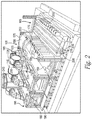
- Figures 2 and 3 provide further detail regarding the structure and operation of the coke plant 100. More specifically, Figures 2 and 3 illustrate further details related to the structure and mechanics of exhaust flow from the ovens to the common tunnel. Figures 4 through 9 provide further details regarding various embodiments of non-perpendicular connections between coke oven uptakes ducts and the common tunnel.
- FIG 2 is an isometric, partial cut-away view of a portion of the HHR coke plant 100 of Figure 1 configured in accordance with embodiments of the technology.
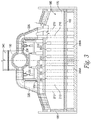
- Figure 3 is a sectional view of an HHR coke oven 105 configured in accordance with embodiments of the technology.
- each oven 105 can include an open cavity defined by a floor 160, a front door 165 forming substantially the entirety of one side of the oven, a rear door 170 opposite the front door 165 forming substantially the entirety of the side of the oven opposite the front door, two sidewalls 175 extending upwardly from the floor 160 intermediate the front 165 and rear 170 doors, and a crown 180 which forms the top surface of the open cavity of an oven chamber 185.
- Controlling air flow and pressure inside the oven chamber 185 can be critical to the efficient operation of the coking cycle, and therefore the front door 165 includes one or more primary air inlets 190 that allow primary combustion air into the oven chamber 185.
- Each primary air inlet 190 includes a primary air damper 195 which can be positioned at any of a number of positions between fully open and fully closed to vary the amount of primary air flow into the oven chamber 185.
- the one or more primary air inlets 190 are formed through the crown 180.
- volatile gases emitted from the coal positioned inside the oven chamber 185 collect in the crown and are drawn downstream in the overall system into downcomer channels 200 formed in one or both sidewalls 175.
- the downcomer channels fluidly connect the oven chamber 185 with a sole flue 205 positioned beneath the oven floor 160.
- the sole flue 205 forms a circuitous path beneath the oven floor 160.
- Volatile gases emitted from the coal can be combusted in the sole flue 205 thereby generating heat to support the carbonization of coal into coke.
- the downcomer channels 200 are fluidly connected to chimneys or uptake channels 210 formed in one or both sidewalls 175.
- a secondary air inlet 215 is provided between the sole flue 205 and the atmosphere; the secondary air inlet 215 includes a secondary air damper 220 that can be positioned at any of a number of positions between fully open and fully closed to vary the amount of secondary air flow into the sole flue 205.
- the uptake channels 210 are fluidly connected to the common tunnel 110 by the one or more uptake ducts 225.
- a tertiary air inlet 227 is provided between the uptake duct 225 and atmosphere.
- the tertiary air inlet 227 includes a tertiary air damper 229 which can be positioned at any of a number of positions between fully open and fully closed to vary the amount of tertiary air flow into the uptake duct 225.
- each uptake duct 225 also includes an uptake damper 230.
- the uptake damper 230 can be positioned at any number of positions between fully open and fully closed to vary the amount of oven draft in the oven 105.
- the uptake damper 230 can comprise any automatic or manually-controlled flow control or orifice blocking device (e.g., any plate, seal, block, etc.).
- "draft" indicates a negative pressure relative to atmosphere. For example, a draft of 0.1 inches of water indicates a pressure of 0.1 inches of water below atmospheric pressure (24.884 Pascal).
- Inches of water is a non-SI unit for pressure and is conventionally used to describe the draft at various locations in a coke plant.
- the draft ranges from about 0.12 (29.8608 Pascal) to about 0.16 inches of water (39.8144 Pascal) in the oven 105. If a draft is increased or otherwise made larger, the pressure moves further below atmospheric pressure. If a draft is decreased, drops, or is otherwise made smaller or lower, the pressure moves towards atmospheric pressure.
- an individual oven 105 includes two uptake ducts 225 and two uptake dampers 230, but the use of two uptake ducts and two uptake dampers is not a necessity; a system can be designed to use just one or more than two uptake ducts and two uptake dampers. All of the ovens 105 are fluidly connected by at least one uptake duct 225 to the common tunnel 110 which is in turn fluidly connected to each HRSG 120 by the crossover ducts 290, 295. The exhaust gases from each oven 105 flow through the common tunnel 110 to the crossover ducts 290, 295.
- coke is produced in the ovens 105 by first loading coal into the oven chamber 185, heating the coal in an oxygen depleted environment, driving off the volatile fraction of coal, and then oxidizing the VM within the oven 105 to capture and utilize the heat given off.
- the coal volatiles are oxidized within the ovens over an extended coking cycle, and release heat to regeneratively drive the carbonization of the coal to coke.
- the coking cycle begins when the front door 165 is opened and coal is charged onto the oven floor 160.
- the coal on the oven floor 160 is known as the coal bed. Heat from the oven (due to the previous coking cycle) starts the carbonization cycle. As discussed above, in some embodiments, no additional fuel other than that produced by the coking process is used.
- each oven 105 is operated at negative pressure so air is drawn into the oven during the reduction process due to the pressure differential between the oven 105 and atmosphere.
- Primary air for combustion is added to the oven chamber 185 to partially oxidize the coal volatiles, but the amount of this primary air is controlled so that only a portion of the volatiles released from the coal are combusted in the oven chamber 185, thereby releasing only a fraction of their enthalpy of combustion within the oven chamber 185.
- the primary air is introduced into the oven chamber 185 above the coal bed through the primary air inlets 190 with the amount of primary air controlled by the primary air dampers 195.
- the primary air dampers 195 can also be used to maintain the desired operating temperature inside the oven chamber 185.
- the partially combusted gases pass from the oven chamber 185 through the downcomer channels 200 into the sole flue 205, where secondary air is added to the partially combusted gases.
- the secondary air is introduced through the secondary air inlet 215.
- the amount of secondary air that is introduced is controlled by the secondary air damper 220.
- the partially combusted gases are more fully combusted in the sole flue 205, thereby extracting the remaining enthalpy of combustion which is conveyed through the oven floor 160 to add heat to the oven chamber 185.
- the fully or nearly-fully combusted exhaust gases exit the sole flue 205 through the uptake channels 210 and then flow into the uptake duct 225.
- Tertiary air is added to the exhaust gases via the tertiary air inlet 227, where the amount of tertiary air introduced is controlled by the tertiary air damper 229 so that any remaining fraction of uncombusted gases in the exhaust gases are oxidized downstream of the tertiary air inlet 227.
- the coal has coked out and has carbonized to produce coke.
- the coke is preferably removed from the oven 105 through the rear door 170 utilizing a mechanical extraction system. Finally, the coke is quenched (e.g., wet or dry quenched) and sized before delivery to a user.
- FIG 4 is a top view of a portion of a horizontal heat recovery coke plant 400 configured in accordance with examples of the technology.
- the coke plant 400 includes several features generally similar to the coke plant 100 described above with reference to Figure 1 .
- the plant 400 includes numerous uptake ducts 425 in fluid communication with coke ovens (not shown) and the hot common tunnel 110.
- the uptake ducts 425 can include "corresponding" uptake ducts 425a, 425b opposite one another on opposing lateral sides of the common tunnel 110 and a most-upstream or "end' uptake duct 425c.
- the uptake ducts 425 can channel exhaust gas to the common tunnel 110.
- the exhaust gas in the common tunnel 110 moves from an "upstream" end toward a "downstream” end.
- the uptake ducts 425 meet the common tunnel 110 at a non-perpendicular interface. More specifically, the uptake ducts 425 have an upstream angle ⁇ relative to the common tunnel 110. While the upstream angle ⁇ is shown to be approximately 45°, it can be lesser or greater in other embodiments. Further, as will be discussed in more detail below, in embodiments according to the claimed invention different uptake ducts 425 have different upstream angles ⁇ from one another.
- the non-perpendicular interfaces between the uptake ducts 425 and the common tunnel 110 can improve flow and reduce draft loss in the manner described above.
- Figure 5A is a cross-sectional top view of a perpendicular interface between an uptake duct 525a and the common tunnel 110 configured in accordance with examples of the technology.
- An uptake flow of exhaust gas in the uptake duct 525a intersects a common flow of exhaust gas in the common tunnel 110 to form a combined flow.
- the uptake duct 525a and the common tunnel 110 meet at an interface having an upstream angle ⁇ 1 and a downstream angle ⁇ 2 which are each approximately 90°.
- a direction of the uptake flow vector comprises an azimuthal y-component but no azimuthal x-component
- a direction of the common flow vector and combined flow vector comprises an x-component but no y-component
- Figure 5B is a cross-sectional top view of a non-perpendicular interface between an uptake duct 525b and the common tunnel 110 configured in accordance with embodiments of the technology.
- the uptake flow from the uptake duct 525b intersects the common flow in the common tunnel 110 to form a combined flow.
- the uptake duct 525b and the common tunnel 110 meet at an interface having an upstream angle ⁇ 1 less than 90° and a downstream angle ⁇ 2 greater than 90°.
- the non-perpendicular interface thus provides an azimuthal commonality between the uptake flow vector and the common flow vector.
- the uptake flow vector comprises an x-component having a direction in common with an x-component of the common flow vector, and the exhaust gas accordingly loses less momentum at the uptake duct 525b and common tunnel 110 interface as compared to the arrangement of Figure 5A .
- the reduced momentum loss can lower the draft loss at the interface or, in some embodiments, can even increase the draft in the common tunnel 110.
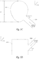
- Figure 5C is a cross-sectional end view of a non-perpendicular interface between an uptake duct 525c and a common tunnel 510c configured in accordance with embodiments of the technology. While previous embodiments have shown the common tunnel to have a generally circular cross-sectional shape, in the embodiment shown in Figure 5C the common tunnel 510c has a generally oval or egg-shaped cross-sectional shape. For example, the common tunnel 510 has a height H between a base B and a top T. In some embodiments, the egg-shaped cross-section can be asymmetrical (i.e., top-heavy), such that the common tunnel 510c has a greater cross-sectional area above a midpoint M between the top T and base B than below the midpoint M.
- the uptake duct 525c can comprise any of the circular or non-circular cross-sectional shapes described above with reference to the common tunnel 510c, and the uptake duct 525c and common tunnel 510c need not have the same cross-sectional shape.
- the uptake flow from the uptake duct 525c intersects the common flow in the common tunnel 510c to form a combined flow.
- the uptake duct 525c meets the common tunnel 510c at an interface having a negative altitude angle ⁇ less than 90° with respect to the horizon (e.g., with respect to the x-y plane).
- the non-perpendicular interface thus provides an altitudinal difference between the uptake flow vector and the common flow vector.
- the uptake flow vector comprises a z-component that differs from a z-component of the common flow vector.
- the altitude angle ⁇ is a positive angle, greater than 90°.
- the uptake duct 525c can interface with the common tunnel 510c at any height between the top T and bottom B of the common tunnel 510c.
- the uptake duct 525c intersects with the common tunnel 510c in the lower portion of the common tunnel 510c (i.e., below or substantially below the midpoint M).
- the uptake duct 525c intersects with the common tunnel 510c in the upper portion of the common tunnel 510c, at the midpoint M, at a top T or bottom B of the common tunnel 510c, or in multiple locations around the cross-sectional circumference of the common tunnel 510c.
- one or more uptake ducts 525c may intersect with the common tunnel 510c in the lower portion and one or more other uptake ducts 525c may intersect with the common tunnel 510c in the upper portion.
- Figure 5D is a cross-sectional end view of a non-perpendicular interface between an uptake duct 525d and the common tunnel 510d configured in accordance with embodiments of the technology.
- the common tunnel 510d has a generally square or rectangular cross-sectional shape. Other embodiments can have other cross-sectional shapes.
- the uptake flow from the uptake duct 525d intersects the common flow in the common tunnel 510d to form a combined flow.
- the uptake duct 525d and the common tunnel 510d meet at an interface having a positive altitude angle ⁇ less than 90° with respect to the horizon.
- the uptake flow vector comprises a z-component that differs from a z-component of the common flow vector.
- mixing draft loss can be reduced and combustion can be encouraged to occur at a height that does not burn the interior surfaces of the common tunnel 510d.
- the downward altitudinal introduction of flow from the uptake duct 525d can counter the buoyancy of the hot exhaust gas to encourage combustion to occur toward the bottom of the common tunnel 510d so as not to burn the top of the common tunnel 501d.
- Figure 5E is a cross-sectional end view of a non-perpendicular interface between an uptake duct 525e and a common tunnel 510e configured in accordance with embodiments of the technology.
- the interface has several features generally similar to those discussed above with reference to Figures 5A-5D .
- the common tunnel 510e comprises a symmetrical, elongated oval. More specifically, the common tunnel 510e includes a semi-circular shape at top and bottom positions of the common tunnel 510e, and generally straight, parallel, elongated sides between the top and bottom semi-circles.
- the elongated shape can provide several of the advantages described above.
- the design can provide for more room in the midsection of the common tunnel 510e for combustion to occur, as the buoyancy of hot exhaust gas tends to urge combustion upward.
- the downward altitudinal introduction of flow from the uptake duct 525e at angle ⁇ can further counter the buoyancy of the hot exhaust gas to encourage combustion to occur toward the bottom of the common tunnel 510e.
- the oblong shape of the illustrated common tunnel 510e can thus minimize flame impingement along the upper surface of the interior of the common tunnel 510e.
- the common tunnel 510e can be symmetrical or asymmetrical and have the same or different shapes.
- the azimuthal angle of interface, the altitudinal angle of interface, the height of interface, the shape of the common tunnel and/or uptake duct, or other feature can be selected to achieve the desired thermal and draft conditions at the interface.
- Various parameters such as common tunnel draft, desired degree of common tunnel combustion, exhaust gas buoyancy conditions, total pressure, etc. can be some of the considerations in selecting the features of the uptake duct and common tunnel interface.
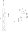
- Figures 6A-6I are top views of various configurations of interfaces between uptake ducts and a common tunnel configured in accordance with examples and embodiments of the technology.
- the uptake ducts can comprise various patterns of perpendicular and non-perpendicular interfaces with the common tunnel, or can comprise various non-perpendicular angles relative to the common tunnel. While the examples and embodiments shown and discussed with reference to Figures 6A-6I include numerous features and arrangements, in further examples and embodiments any of these features and/or arrangements can be used independently or in any combination with other features and/or arrangements described herein.
- each of several uptake ducts 625a meets the common tunnel 110 at a less-than-90° upstream angle ⁇ .
- the uptake ducts 625a thus reduce mixing loss at the combination of common flow and uptake flow in the manner described above.
- corresponding (i.e., opposing) uptake ducts 625a are laterally offset from one another and are not directly opposing. This is shown in the two most-downstream uptake ducts 625a shown in Figure 6A .
- the spacing between individual uptake ducts 625a i.e., along the length of the common tunnel 110) can likewise be variable.
- the distance d between the two most downstream uptake ducts 625a along one side of the common tunnel 110 is greater than the distance between the other uptake ducts 625a.
- the spacing is constant between all uptake ducts 625a.
- Figure 6B illustrates an embodiment according to the presently claimed invention where uptake ducts 625b meet the common tunnel 110 at decreasing upstream angles ⁇ .
- the uptake ducts may be perpendicular or nearly-perpendicular to the common tunnel 110.
- the upstream angles ⁇ between the uptake ducts 625b and the common tunnel 110 become progressively smaller.
- the range of upstream angles ⁇ varies from about 15° to about 90°. Since the draft pull is weaker farther upstream, this arrangement can progressively reduce the barrier to entry of the uptake flow into the common flow and thereby reduce draft loss due to mixing or stagnant flow regions.
- one or more uptake ducts 625b can be positioned at an upstream angle ⁇ that is greater than 90°.
- the trend shown in Figure 6B can be reversed. More specifically, the uptake ducts 625b can meet the common tunnel 110 at increasing upstream angles, wherein the most-upstream angle can be near or approaching 90°. Such an arrangement can be useful in embodiments where mixing flow losses are potentially greater at downstream positions having higher accumulated common flow.
- Figure 6C illustrates an example having a combination of uptake ducts 625c meeting the common tunnel 110 at non-perpendicular angles ⁇ 1 and perpendicular angles ⁇ 2.
- the illustrated example includes pairs of non-perpendicular ducts 625c along a side of the common tunnel 110 followed by pairs of perpendicular ducts 625c, and so on.
- Figure 6D illustrates an example having a combination of uptake ducts 625d meeting the common tunnel 110 at non-perpendicular angles ⁇ 1 and perpendicular angles ⁇ 2.
- the illustrated example includes alternating non-perpendicular ducts 625d and perpendicular ducts 625d along a side of the common tunnel 110.
- Figure 6E illustrates an example having a combination of uptake ducts 625e meeting the common tunnel 110 at non-perpendicular angles ⁇ 1 and perpendicular angles ⁇ 2.
- the illustrated example includes individual perpendicular uptake ducts 625e alternating with non-perpendicular uptake ducts 625e, followed by pairs of non-perpendicular ducts 625e, followed by pairs of perpendicular ducts 625e, and so on. This pattern or a portion of this pattern can repeat along further sections of the common tunnel 110. In further examples, there can be different combinations of perpendicular and non-perpendicular uptake ducts.
- Figure 6F illustrates an example having a combination of uptake ducts 625f meeting the common tunnel 110 at non-perpendicular angles ⁇ 1 and perpendicular angles ⁇ 2.
- the illustrated example includes a series of non-perpendicular uptake ducts 625f, followed by a perpendicular duct 625f, followed by another series of non-perpendicular ducts 625f, and so on.
- Figure 6G illustrates an example having a combination of uptake ducts 625g meeting the common tunnel 110 at non-perpendicular angles ⁇ 1 and perpendicular angles ⁇ 2.
- the illustrated example includes non-perpendicular uptake ducts 625g on a first lateral side of the common tunnel 110, and perpendicular ducts 625g along a second, opposing, lateral side of the common tunnel 110.
- Figure 6H illustrates an example having a combination of uptake ducts 625h meeting the common tunnel 110 at non-perpendicular angles ⁇ 1 and perpendicular angles ⁇ 2.
- the illustrated example includes alternating non-perpendicular ducts 625h and perpendicular ducts 625h along a side of the common tunnel 110, where the non-perpendicular uptake ducts 625h are opposite perpendicular ducts 625h and vice-versa.
- Figure 6I illustrates an example having uptake ducts 625i along only one lateral side of the common tunnel 110, with no uptake ducts on the opposing lateral side.
- two single-sided common tunnels 110 can be operated in a coke plant in a side-by-side parallel arrangement.
- the uptake ducts 625i can be angled at non-perpendicular angle a relative to the common tunnel 110 in the manner described above.
- Figure 7A is a cross-sectional top view of a non-perpendicular interface retrofitted between a perpendicular uptake duct 725a and the common tunnel 110 configured in accordance with examples of the technology.
- the uptake duct 725a and the common tunnel 110 can originally have the same arrangement as the example discussed above with reference to Figure 5A , but can be retrofitted to include one or more non-perpendicular interface features.
- the interface has been fitted with an internal baffle 726a to alter the flow pattern and create a non-perpendicular interface. More specifically, the baffle 726a is placed in a lumen of the uptake duct 725a and modifies a perpendicular interface into an angled interface that reduces draft loss due to mixing.
- the baffle 726a is triangle-shaped and converges the uptake flow by reducing an inner characteristic dimension of the uptake duct 725a. This converged flow can act as a nozzle and minimize flow energy losses of the uptake flow and/or common flow.
- the baffle 726a can be adjustable (i.e., movable to adjust the flow and interface pattern), can have different shapes and/or sizes, and/or can converge and/or diverge flow to other degrees. Further, the baffle can extend around more or less of the lumen of the uptake duct 725a.
- the common tunnel 110 can further be retrofitted with a flow modifier 703 positioned on an interior surface of the common tunnel 110 and configured to interrupt or otherwise modify flow in the common tunnel 110, or improve the interface (i.e., reduce draft loss) at the junction of the uptake flow and the common flow.
- the uptake duct 725a has further been modified with a bumped-out diverging flow plate D.
- the diverging flow plate D modifies the uptake flow vector to have an x-component in common with a common flow vector, thus reducing draft loss between the uptake flow and the common flow. While the diverging flow plate D, the baffle 726a, and the flow modifier 703 are shown in use together, in further examples, any of these features can be used independently or in any combination with any other features described herein.
- baffle 726a and “flow modifier” 703 are used herein, the additions to the uptake duct 726a or common tunnel 110 can comprise any insulation material, refractory material, or other thermally-suitable material.
- the flow modifier 703 and/or baffle 726a may comprise a single or multilayer lining that is built up with a relatively inexpensive material and covered with a skin.
- refractory or similar material can be shaped via gunning (i.e. spraying). Better control of shaping via gunning may be accomplished by gunning in small increments or layers.
- a template or mold may be used to aid the shaping via gunning.
- a template, mold, or advanced cutting techniques may be used to shape the refractory (e.g. even in the absence of gunning for the main shape of an internal insert) for insertion into the duct and then attached via gunning to the inner lining of the duct.
- the flow modifier 703 and/or baffle 726a may be integrally formed along the duct.
- the uptake duct 725a wall may be formed or "dented" to provide a convex surface along the interior surface of the duct.
- convex does not require a continuous smooth surface, although a smooth surface may be desirable.
- the flow modifier 703 and/or baffle 726a may be in the form of a multi-faceted protrusion extending into the flow path. Such a protrusion may be comprised of multiple discontinuous panels and/or surfaces.
- the flow modifier 703 and/or baffle 726a are not limited to convex surfaces.
- the contours of the flow modifier 703 and/or baffle 726a may have other complex surfaces, and can be determined by design considerations such as cost, space, operating conditions, etc. In further examples, there can be more than one flow modifier 703 and/or baffle 726a.
- the flow modifier 703 is shown in the common tunnel 110, in further examples the flow modifier 703 can be positioned at other locations (e.g., entirely or partially extending into the uptake duct 725a, or around the inner circumference of the common tunnel 110.
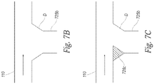
- Figure 7B is a cross-sectional top view of an interface between an uptake duct 725b and a common tunnel 110 configured in accordance with examples of the technology.
- Figure 7C is a cross-sectional top view of a non-perpendicular interface retrofitted between the uptake duct 725b and common tunnel 110 of Figure 7B .
- the uptake duct 725b includes a diverging uptake end D that flares at the interface with the common tunnel 110.
- the uptake duct 725b can be retrofitted with an internal baffle 726c generally similar to the internal baffle 726a described above with reference to Figure 7A .
- the internal baffle 726c of Figure 7C can eliminate the flare or a portion of the flare at the diverging end D, to create a non-perpendicular interface between the uptake duct 725b and the common tunnel 110 to reduce draft loss.
- the entire internal circumference of the uptake duct 725b can be fitted with the baffle 726c to further narrow or otherwise alter the interface.
- the baffle 726c can minimize flow energy losses as the uptake flow meets the common flow in the common tunnel 110.
- Figure 8 is a cross-sectional top view of a non-perpendicular interface between an uptake duct 825 and the common tunnel 110 configured in accordance with examples of the technology.
- the uptake duct 825 includes a converging portion C followed by a diverging portion D.
- the converging portion C can minimize flow energy losses as the exhaust gas from the uptake duct 825 meets the common flow in the common tunnel 110.
- the diverging portion provides an interface that modifies the uptake flow vector to have an x-component in common with a common flow vector, thus reducing draft loss between the pressurized uptake flow and the common flow.
- the diverging and converging portions can have smooth or sharp transitions, and there can be more or fewer converging or diverging nozzles in the uptake duct 825 or common tunnel 110.
- the converging portion C is adjacent to the common tunnel 110 and the diverging portion D is upstream in the uptake duct 825.
- the converging portion C can be used independently from the diverging portion D, and vice versa.
- the interface of Figure 8 further includes a jet 803 configured to introduce a pressurized fluid such as air, exhaust gas, water, steam, fuel, oxidizer, inert, or other fluid (or combination of fluids) to the uptake flow or common flow as a way to improve flow and reduce draft loss.
- a pressurized fluid such as air, exhaust gas, water, steam, fuel, oxidizer, inert, or other fluid (or combination of fluids)
- the fluid can be gaseous, liquid, or multiphase.
- the jet 803 can stem from or be supported by any external or internal pressurized source (e.g., a pressurized vessel, a pressurized line, a compressor, a chemical reaction or burning within the coking oven system that supports energy to create pressure, etc.).
- the jet 803 is shown as penetrating the common tunnel 110 at a position downstream of the uptake duct 825, in further examples the jet 803 can be positioned in the uptake duct 825, upstream of the uptake duct 825 in the common tunnel 110, in multiple locations (e.g., a ring) around the circumference of the common tunnel 110 or uptake duct 825a, a combination of these positions, or other positions.
- the jet 803 can be positioned in the uptake duct 825 upstream of the converging portion C.
- the jet 803 can act as an ejector, and can pull a vacuum draft behind the pressurized fluid.
- the jet 803 can thus modify flow to create improved draft conditions, energize flow or mixing, or can reduce stagnant air or "dead" zones.
- the jet 803 can pulse the fluid, provide constant fluid, or be run on a timer.
- the jet 803 can be controlled manually, in response to conditions in the common tunnel 110, uptake duct 825, or other portion of the exhaust system, or as part of an advanced control regime. While the jet 803 is shown in use with the particular uptake duct 825 arrangement illustrated in Figure 8 , in further examples, the jet 803 and uptake duct 825 could be employed independently or in any combination with any other features described herein.
- the jet 803 could be used in combination with the flow modifier 703 shown in Figure 7A , and could be proximate to or protrude through such a flow modifier 703.
- Figure 9 is a plot showing the spatial distribution of the difference in static pressure (in inches-water) along the length of the common tunnel.
- the plot illustrates the difference in static pressure at downstream positions in the common tunnel compared to the static pressure at the upstream end.
- the 45 degree uptake has a much lower draft loss over the same length of common tunnel as compared to the perpendicular uptake. This is because the angled uptake has less mixing loss than the perpendicular uptake.
- the non-perpendicular interfaces disclosed herein can lower the mixing draft loss at the uptake/common tunnel connection by angling the connection in the direction of the common tunnel flow.
- the draft loss can be lowered, which then can be used to reduce the common tunnel size or lower the required draft.
- the technology described herein can reduce the common tunnel insider diameter to 7-9 feet (2.13-2.74 metres). The technology could similarly allow a longer common tunnel that would traditionally have been prohibitive due to draft losses.
- the common tunnel can be long enough to support 30, 45, 60, or more ovens per side.
Landscapes
- Chemical & Material Sciences (AREA)
- Engineering & Computer Science (AREA)
- Materials Engineering (AREA)
- Oil, Petroleum & Natural Gas (AREA)
- Organic Chemistry (AREA)
- Waste-Gas Treatment And Other Accessory Devices For Furnaces (AREA)
- Coke Industry (AREA)
- Treating Waste Gases (AREA)
Priority Applications (1)
| Application Number | Priority Date | Filing Date | Title |
|---|---|---|---|
| PL14768073T PL2970768T3 (pl) | 2013-03-14 | 2014-03-14 | System koksowniczy z nieprostopadłymi połączeniami między przewodami wznoszącymi pieca koksowniczego a gorącym wspólnym tunelem oraz sposób zmniejszania strat ciągu |
Applications Claiming Priority (2)
| Application Number | Priority Date | Filing Date | Title |
|---|---|---|---|
| US13/830,971 US10047295B2 (en) | 2012-12-28 | 2013-03-14 | Non-perpendicular connections between coke oven uptakes and a hot common tunnel, and associated systems and methods |
| PCT/US2014/028019 WO2014152860A1 (en) | 2013-03-14 | 2014-03-14 | Non-perpendicular connections between coke oven uptakes and a hot common tunnel, and associated systems and methods |
Publications (3)
| Publication Number | Publication Date |
|---|---|
| EP2970768A1 EP2970768A1 (en) | 2016-01-20 |
| EP2970768A4 EP2970768A4 (en) | 2016-11-02 |
| EP2970768B1 true EP2970768B1 (en) | 2021-09-01 |
Family
ID=51581338
Family Applications (1)
| Application Number | Title | Priority Date | Filing Date |
|---|---|---|---|
| EP14768073.0A Active EP2970768B1 (en) | 2013-03-14 | 2014-03-14 | Coking system with non-perpendicular connections between coke oven uptakes and a hot common tunnel and method for reducing draft losses |
Country Status (5)
| Country | Link |
|---|---|
| EP (1) | EP2970768B1 (pl) |
| CN (1) | CN105189703B (pl) |
| CA (1) | CA2906066C (pl) |
| PL (1) | PL2970768T3 (pl) |
| WO (1) | WO2014152860A1 (pl) |
Families Citing this family (1)
| Publication number | Priority date | Publication date | Assignee | Title |
|---|---|---|---|---|
| JP7155994B2 (ja) * | 2018-12-19 | 2022-10-19 | 日本製鉄株式会社 | コークス炉ガスの燃焼放散管及び燃焼放散方法 |
Family Cites Families (12)
| Publication number | Priority date | Publication date | Assignee | Title |
|---|---|---|---|---|
| US1140798A (en) * | 1915-01-02 | 1915-05-25 | Riterconley Mfg Company | Coal-gas-generating apparatus. |
| US3545470A (en) * | 1967-07-24 | 1970-12-08 | Hamilton Neil King Paton | Differential-pressure flow-controlling valve mechanism |
| DE2326825A1 (de) * | 1973-05-25 | 1975-01-02 | Hartung Kuhn & Co Maschf | Einrichtung zum abfuehren und reinigen von an den tueren an horizontalkammerverkokungsofenbatterien austretenden gasschwaden |
| US4045299A (en) * | 1975-11-24 | 1977-08-30 | Pennsylvania Coke Technology, Inc. | Smokeless non-recovery type coke oven |
| DE3037950C2 (de) * | 1980-10-08 | 1985-09-12 | Dr. C. Otto & Co Gmbh, 4630 Bochum | Einrichtung zur Verbesserung des Strömungsverlaufes in den Überführungskanälen, die zwischen den Regeneratoren bzw. Rekuperatoren und den Verbrennungsräumen von technischen Gasfeuerungen, insbesondere von Koksöfen, angeordnet sind |
| CN87212113U (zh) * | 1987-08-22 | 1988-06-29 | 戴春亭 | 炼焦炉 |
| US5114542A (en) * | 1990-09-25 | 1992-05-19 | Jewell Coal And Coke Company | Nonrecovery coke oven battery and method of operation |
| CN1084782C (zh) * | 1999-12-09 | 2002-05-15 | 山西三佳煤化有限公司 | 联体式炼焦炉及其炼焦方法 |
| JP2002106941A (ja) * | 2000-09-29 | 2002-04-10 | Kajima Corp | 分岐・合流用ヘッダーダクトユニット |
| US6596128B2 (en) * | 2001-02-14 | 2003-07-22 | Sun Coke Company | Coke oven flue gas sharing |
| CN2521473Y (zh) * | 2001-12-27 | 2002-11-20 | 杨正德 | 导流三通 |
| US7736470B2 (en) * | 2007-01-25 | 2010-06-15 | Exxonmobil Research And Engineering Company | Coker feed method and apparatus |
-
2014
- 2014-03-14 PL PL14768073T patent/PL2970768T3/pl unknown
- 2014-03-14 CA CA2906066A patent/CA2906066C/en active Active
- 2014-03-14 CN CN201480014884.4A patent/CN105189703B/zh active Active
- 2014-03-14 EP EP14768073.0A patent/EP2970768B1/en active Active
- 2014-03-14 WO PCT/US2014/028019 patent/WO2014152860A1/en not_active Ceased
Also Published As
| Publication number | Publication date |
|---|---|
| PL2970768T3 (pl) | 2022-01-17 |
| BR112015023324A2 (pt) | 2017-07-18 |
| CN105189703B (zh) | 2018-02-02 |
| CA2906066A1 (en) | 2014-09-25 |
| EP2970768A4 (en) | 2016-11-02 |
| WO2014152860A1 (en) | 2014-09-25 |
| CA2906066C (en) | 2022-05-31 |
| EP2970768A1 (en) | 2016-01-20 |
| CN105189703A (zh) | 2015-12-23 |
Similar Documents
| Publication | Publication Date | Title |
|---|---|---|
| US11008517B2 (en) | Non-perpendicular connections between coke oven uptakes and a hot common tunnel, and associated systems and methods | |
| US9273249B2 (en) | Systems and methods for controlling air distribution in a coke oven | |
| US12325828B2 (en) | Exhaust flow modifier, duct intersection incorporating the same, and methods therefor | |
| CA2896477C (en) | Systems and methods for controlling air distribution in a coke oven | |
| US11441078B2 (en) | Burn profiles for coke operations | |
| US6187148B1 (en) | Downcomer valve for non-recovery coke oven | |
| CN102517042B (zh) | 一种可控制多段燃烧的焦炉加热方法 | |
| US9790570B2 (en) | Apparatus and method for the thermal treatment of lump or agglomerated material | |
| CN106838889A (zh) | 一种带内循环灰换热器的循环流化床锅炉 | |
| EP2970768B1 (en) | Coking system with non-perpendicular connections between coke oven uptakes and a hot common tunnel and method for reducing draft losses | |
| CN104884577B (zh) | 排气流动调节器和具有该调节器的管道交叉装置及相关方法 | |
| BR112015023324B1 (pt) | Sistemas de coque | |
| CN104329799B (zh) | 一种具有v型细缝的梯形炉排热风炉 | |
| CN103438696A (zh) | 熔铝反射炉富氧局部增氧射流助燃节能减排系统 | |
| CN104870614B (zh) | 用于控制在焦炉中的空气分配的系统和方法 | |
| RU2811610C1 (ru) | Новая конструкция коксовой печи и способ её горения с секционным нагревом | |
| CN116574522A (zh) | 一种热回收焦炉吸力调节结构 | |
| JPH05302708A (ja) | ダクト内を流れるガスの昇温方法および装置 |
Legal Events
| Date | Code | Title | Description |
|---|---|---|---|
| PUAI | Public reference made under article 153(3) epc to a published international application that has entered the european phase |
Free format text: ORIGINAL CODE: 0009012 |
|
| 17P | Request for examination filed |
Effective date: 20150803 |
|
| AK | Designated contracting states |
Kind code of ref document: A1 Designated state(s): AL AT BE BG CH CY CZ DE DK EE ES FI FR GB GR HR HU IE IS IT LI LT LU LV MC MK MT NL NO PL PT RO RS SE SI SK SM TR |
|
| AX | Request for extension of the european patent |
Extension state: BA ME |
|
| DAX | Request for extension of the european patent (deleted) | ||
| REG | Reference to a national code |
Ref country code: DE Ref legal event code: R079 Ref document number: 602014079849 Country of ref document: DE Free format text: PREVIOUS MAIN CLASS: C10B0005080000 Ipc: C10B0015020000 |
|
| A4 | Supplementary search report drawn up and despatched |
Effective date: 20160930 |
|
| RIC1 | Information provided on ipc code assigned before grant |
Ipc: C10B 5/08 20060101ALI20160926BHEP Ipc: C10B 5/16 20060101ALI20160926BHEP Ipc: C10B 45/00 20060101ALI20160926BHEP Ipc: C10B 15/02 20060101AFI20160926BHEP |
|
| STAA | Information on the status of an ep patent application or granted ep patent |
Free format text: STATUS: EXAMINATION IS IN PROGRESS |
|
| 17Q | First examination report despatched |
Effective date: 20171010 |
|
| RAP1 | Party data changed (applicant data changed or rights of an application transferred) |
Owner name: SUNCOKE TECHNOLOGY AND DEVELOPMENT LLC |
|
| GRAP | Despatch of communication of intention to grant a patent |
Free format text: ORIGINAL CODE: EPIDOSNIGR1 |
|
| STAA | Information on the status of an ep patent application or granted ep patent |
Free format text: STATUS: GRANT OF PATENT IS INTENDED |
|
| INTG | Intention to grant announced |
Effective date: 20210331 |
|
| GRAS | Grant fee paid |
Free format text: ORIGINAL CODE: EPIDOSNIGR3 |
|
| GRAA | (expected) grant |
Free format text: ORIGINAL CODE: 0009210 |
|
| STAA | Information on the status of an ep patent application or granted ep patent |
Free format text: STATUS: THE PATENT HAS BEEN GRANTED |
|
| AK | Designated contracting states |
Kind code of ref document: B1 Designated state(s): AL AT BE BG CH CY CZ DE DK EE ES FI FR GB GR HR HU IE IS IT LI LT LU LV MC MK MT NL NO PL PT RO RS SE SI SK SM TR |
|
| REG | Reference to a national code |
Ref country code: GB Ref legal event code: FG4D |
|
| REG | Reference to a national code |
Ref country code: CH Ref legal event code: EP Ref country code: AT Ref legal event code: REF Ref document number: 1426266 Country of ref document: AT Kind code of ref document: T Effective date: 20210915 |
|
| REG | Reference to a national code |
Ref country code: DE Ref legal event code: R096 Ref document number: 602014079849 Country of ref document: DE |
|
| REG | Reference to a national code |
Ref country code: IE Ref legal event code: FG4D |
|
| REG | Reference to a national code |
Ref country code: LT Ref legal event code: MG9D |
|
| REG | Reference to a national code |
Ref country code: NL Ref legal event code: MP Effective date: 20210901 |
|
| PG25 | Lapsed in a contracting state [announced via postgrant information from national office to epo] |
Ref country code: HR Free format text: LAPSE BECAUSE OF FAILURE TO SUBMIT A TRANSLATION OF THE DESCRIPTION OR TO PAY THE FEE WITHIN THE PRESCRIBED TIME-LIMIT Effective date: 20210901 Ref country code: SE Free format text: LAPSE BECAUSE OF FAILURE TO SUBMIT A TRANSLATION OF THE DESCRIPTION OR TO PAY THE FEE WITHIN THE PRESCRIBED TIME-LIMIT Effective date: 20210901 Ref country code: RS Free format text: LAPSE BECAUSE OF FAILURE TO SUBMIT A TRANSLATION OF THE DESCRIPTION OR TO PAY THE FEE WITHIN THE PRESCRIBED TIME-LIMIT Effective date: 20210901 Ref country code: LT Free format text: LAPSE BECAUSE OF FAILURE TO SUBMIT A TRANSLATION OF THE DESCRIPTION OR TO PAY THE FEE WITHIN THE PRESCRIBED TIME-LIMIT Effective date: 20210901 Ref country code: BG Free format text: LAPSE BECAUSE OF FAILURE TO SUBMIT A TRANSLATION OF THE DESCRIPTION OR TO PAY THE FEE WITHIN THE PRESCRIBED TIME-LIMIT Effective date: 20211201 Ref country code: ES Free format text: LAPSE BECAUSE OF FAILURE TO SUBMIT A TRANSLATION OF THE DESCRIPTION OR TO PAY THE FEE WITHIN THE PRESCRIBED TIME-LIMIT Effective date: 20210901 Ref country code: FI Free format text: LAPSE BECAUSE OF FAILURE TO SUBMIT A TRANSLATION OF THE DESCRIPTION OR TO PAY THE FEE WITHIN THE PRESCRIBED TIME-LIMIT Effective date: 20210901 Ref country code: NO Free format text: LAPSE BECAUSE OF FAILURE TO SUBMIT A TRANSLATION OF THE DESCRIPTION OR TO PAY THE FEE WITHIN THE PRESCRIBED TIME-LIMIT Effective date: 20211201 |
|
| REG | Reference to a national code |
Ref country code: AT Ref legal event code: UEP Ref document number: 1426266 Country of ref document: AT Kind code of ref document: T Effective date: 20210901 |
|
| PG25 | Lapsed in a contracting state [announced via postgrant information from national office to epo] |
Ref country code: LV Free format text: LAPSE BECAUSE OF FAILURE TO SUBMIT A TRANSLATION OF THE DESCRIPTION OR TO PAY THE FEE WITHIN THE PRESCRIBED TIME-LIMIT Effective date: 20210901 Ref country code: GR Free format text: LAPSE BECAUSE OF FAILURE TO SUBMIT A TRANSLATION OF THE DESCRIPTION OR TO PAY THE FEE WITHIN THE PRESCRIBED TIME-LIMIT Effective date: 20211202 |
|
| PG25 | Lapsed in a contracting state [announced via postgrant information from national office to epo] |
Ref country code: IS Free format text: LAPSE BECAUSE OF FAILURE TO SUBMIT A TRANSLATION OF THE DESCRIPTION OR TO PAY THE FEE WITHIN THE PRESCRIBED TIME-LIMIT Effective date: 20220101 Ref country code: SM Free format text: LAPSE BECAUSE OF FAILURE TO SUBMIT A TRANSLATION OF THE DESCRIPTION OR TO PAY THE FEE WITHIN THE PRESCRIBED TIME-LIMIT Effective date: 20210901 Ref country code: SK Free format text: LAPSE BECAUSE OF FAILURE TO SUBMIT A TRANSLATION OF THE DESCRIPTION OR TO PAY THE FEE WITHIN THE PRESCRIBED TIME-LIMIT Effective date: 20210901 Ref country code: RO Free format text: LAPSE BECAUSE OF FAILURE TO SUBMIT A TRANSLATION OF THE DESCRIPTION OR TO PAY THE FEE WITHIN THE PRESCRIBED TIME-LIMIT Effective date: 20210901 Ref country code: PT Free format text: LAPSE BECAUSE OF FAILURE TO SUBMIT A TRANSLATION OF THE DESCRIPTION OR TO PAY THE FEE WITHIN THE PRESCRIBED TIME-LIMIT Effective date: 20220103 Ref country code: NL Free format text: LAPSE BECAUSE OF FAILURE TO SUBMIT A TRANSLATION OF THE DESCRIPTION OR TO PAY THE FEE WITHIN THE PRESCRIBED TIME-LIMIT Effective date: 20210901 Ref country code: EE Free format text: LAPSE BECAUSE OF FAILURE TO SUBMIT A TRANSLATION OF THE DESCRIPTION OR TO PAY THE FEE WITHIN THE PRESCRIBED TIME-LIMIT Effective date: 20210901 Ref country code: CZ Free format text: LAPSE BECAUSE OF FAILURE TO SUBMIT A TRANSLATION OF THE DESCRIPTION OR TO PAY THE FEE WITHIN THE PRESCRIBED TIME-LIMIT Effective date: 20210901 Ref country code: AL Free format text: LAPSE BECAUSE OF FAILURE TO SUBMIT A TRANSLATION OF THE DESCRIPTION OR TO PAY THE FEE WITHIN THE PRESCRIBED TIME-LIMIT Effective date: 20210901 |
|
| PGFP | Annual fee paid to national office [announced via postgrant information from national office to epo] |
Ref country code: PL Payment date: 20220215 Year of fee payment: 9 Ref country code: LU Payment date: 20220314 Year of fee payment: 9 |
|
| REG | Reference to a national code |
Ref country code: DE Ref legal event code: R097 Ref document number: 602014079849 Country of ref document: DE |
|
| PLBE | No opposition filed within time limit |
Free format text: ORIGINAL CODE: 0009261 |
|
| STAA | Information on the status of an ep patent application or granted ep patent |
Free format text: STATUS: NO OPPOSITION FILED WITHIN TIME LIMIT |
|
| PG25 | Lapsed in a contracting state [announced via postgrant information from national office to epo] |
Ref country code: IT Free format text: LAPSE BECAUSE OF FAILURE TO SUBMIT A TRANSLATION OF THE DESCRIPTION OR TO PAY THE FEE WITHIN THE PRESCRIBED TIME-LIMIT Effective date: 20210901 Ref country code: DK Free format text: LAPSE BECAUSE OF FAILURE TO SUBMIT A TRANSLATION OF THE DESCRIPTION OR TO PAY THE FEE WITHIN THE PRESCRIBED TIME-LIMIT Effective date: 20210901 |
|
| 26N | No opposition filed |
Effective date: 20220602 |
|
| PG25 | Lapsed in a contracting state [announced via postgrant information from national office to epo] |
Ref country code: SI Free format text: LAPSE BECAUSE OF FAILURE TO SUBMIT A TRANSLATION OF THE DESCRIPTION OR TO PAY THE FEE WITHIN THE PRESCRIBED TIME-LIMIT Effective date: 20210901 |
|
| PG25 | Lapsed in a contracting state [announced via postgrant information from national office to epo] |
Ref country code: MC Free format text: LAPSE BECAUSE OF FAILURE TO SUBMIT A TRANSLATION OF THE DESCRIPTION OR TO PAY THE FEE WITHIN THE PRESCRIBED TIME-LIMIT Effective date: 20210901 |
|
| REG | Reference to a national code |
Ref country code: CH Ref legal event code: PL |
|
| REG | Reference to a national code |
Ref country code: BE Ref legal event code: MM Effective date: 20220331 |
|
| PG25 | Lapsed in a contracting state [announced via postgrant information from national office to epo] |
Ref country code: LI Free format text: LAPSE BECAUSE OF NON-PAYMENT OF DUE FEES Effective date: 20220331 Ref country code: IE Free format text: LAPSE BECAUSE OF NON-PAYMENT OF DUE FEES Effective date: 20220314 Ref country code: FR Free format text: LAPSE BECAUSE OF NON-PAYMENT OF DUE FEES Effective date: 20220331 Ref country code: CH Free format text: LAPSE BECAUSE OF NON-PAYMENT OF DUE FEES Effective date: 20220331 |
|
| PG25 | Lapsed in a contracting state [announced via postgrant information from national office to epo] |
Ref country code: BE Free format text: LAPSE BECAUSE OF NON-PAYMENT OF DUE FEES Effective date: 20220331 |
|
| PG25 | Lapsed in a contracting state [announced via postgrant information from national office to epo] |
Ref country code: LU Free format text: LAPSE BECAUSE OF NON-PAYMENT OF DUE FEES Effective date: 20230314 |
|
| PG25 | Lapsed in a contracting state [announced via postgrant information from national office to epo] |
Ref country code: HU Free format text: LAPSE BECAUSE OF FAILURE TO SUBMIT A TRANSLATION OF THE DESCRIPTION OR TO PAY THE FEE WITHIN THE PRESCRIBED TIME-LIMIT; INVALID AB INITIO Effective date: 20140314 |
|
| PGFP | Annual fee paid to national office [announced via postgrant information from national office to epo] |
Ref country code: AT Payment date: 20240319 Year of fee payment: 11 |
|
| PG25 | Lapsed in a contracting state [announced via postgrant information from national office to epo] |
Ref country code: MK Free format text: LAPSE BECAUSE OF FAILURE TO SUBMIT A TRANSLATION OF THE DESCRIPTION OR TO PAY THE FEE WITHIN THE PRESCRIBED TIME-LIMIT Effective date: 20210901 Ref country code: CY Free format text: LAPSE BECAUSE OF FAILURE TO SUBMIT A TRANSLATION OF THE DESCRIPTION OR TO PAY THE FEE WITHIN THE PRESCRIBED TIME-LIMIT Effective date: 20210901 |
|
| PGFP | Annual fee paid to national office [announced via postgrant information from national office to epo] |
Ref country code: DE Payment date: 20240319 Year of fee payment: 11 |
|
| PG25 | Lapsed in a contracting state [announced via postgrant information from national office to epo] |
Ref country code: TR Free format text: LAPSE BECAUSE OF FAILURE TO SUBMIT A TRANSLATION OF THE DESCRIPTION OR TO PAY THE FEE WITHIN THE PRESCRIBED TIME-LIMIT Effective date: 20210901 |
|
| PG25 | Lapsed in a contracting state [announced via postgrant information from national office to epo] |
Ref country code: MT Free format text: LAPSE BECAUSE OF FAILURE TO SUBMIT A TRANSLATION OF THE DESCRIPTION OR TO PAY THE FEE WITHIN THE PRESCRIBED TIME-LIMIT Effective date: 20210901 |
|
| PG25 | Lapsed in a contracting state [announced via postgrant information from national office to epo] |
Ref country code: PL Free format text: LAPSE BECAUSE OF NON-PAYMENT OF DUE FEES Effective date: 20230314 |
|
| PG25 | Lapsed in a contracting state [announced via postgrant information from national office to epo] |
Ref country code: PL Free format text: LAPSE BECAUSE OF NON-PAYMENT OF DUE FEES Effective date: 20230314 |
|
| REG | Reference to a national code |
Ref country code: DE Ref legal event code: R119 Ref document number: 602014079849 Country of ref document: DE |
|
| REG | Reference to a national code |
Ref country code: AT Ref legal event code: MM01 Ref document number: 1426266 Country of ref document: AT Kind code of ref document: T Effective date: 20250314 |
|
| PG25 | Lapsed in a contracting state [announced via postgrant information from national office to epo] |
Ref country code: DE Free format text: LAPSE BECAUSE OF NON-PAYMENT OF DUE FEES Effective date: 20251001 |
|
| PG25 | Lapsed in a contracting state [announced via postgrant information from national office to epo] |
Ref country code: AT Free format text: LAPSE BECAUSE OF NON-PAYMENT OF DUE FEES Effective date: 20250314 |
|
| PGFP | Annual fee paid to national office [announced via postgrant information from national office to epo] |
Ref country code: GB Payment date: 20260213 Year of fee payment: 13 |