EP2969832B1 - Article pour enliassage des articles entre eux - Google Patents
Article pour enliassage des articles entre eux Download PDFInfo
- Publication number
- EP2969832B1 EP2969832B1 EP14717270.4A EP14717270A EP2969832B1 EP 2969832 B1 EP2969832 B1 EP 2969832B1 EP 14717270 A EP14717270 A EP 14717270A EP 2969832 B1 EP2969832 B1 EP 2969832B1
- Authority
- EP
- European Patent Office
- Prior art keywords
- panel
- aperture
- stretchable
- elastomer element
- bundling article
- Prior art date
- Legal status (The legal status is an assumption and is not a legal conclusion. Google has not performed a legal analysis and makes no representation as to the accuracy of the status listed.)
- Active
Links
- 229920001971 elastomer Polymers 0.000 claims description 116
- 239000000806 elastomer Substances 0.000 claims description 116
- 238000000034 method Methods 0.000 claims description 26
- 239000000463 material Substances 0.000 description 38
- 210000003739 neck Anatomy 0.000 description 14
- 239000010410 layer Substances 0.000 description 12
- 239000000853 adhesive Substances 0.000 description 6
- 230000001070 adhesive effect Effects 0.000 description 6
- 238000004519 manufacturing process Methods 0.000 description 6
- -1 polyethylene terephthalate Polymers 0.000 description 6
- 230000000717 retained effect Effects 0.000 description 6
- XLYOFNOQVPJJNP-UHFFFAOYSA-N water Substances O XLYOFNOQVPJJNP-UHFFFAOYSA-N 0.000 description 6
- 238000005520 cutting process Methods 0.000 description 5
- 239000000976 ink Substances 0.000 description 5
- 230000036961 partial effect Effects 0.000 description 5
- 241000196324 Embryophyta Species 0.000 description 4
- 230000008901 benefit Effects 0.000 description 3
- 239000000203 mixture Substances 0.000 description 3
- 239000004698 Polyethylene Substances 0.000 description 2
- 239000004743 Polypropylene Substances 0.000 description 2
- 230000015556 catabolic process Effects 0.000 description 2
- 239000011248 coating agent Substances 0.000 description 2
- 238000000576 coating method Methods 0.000 description 2
- 238000006731 degradation reaction Methods 0.000 description 2
- 230000000694 effects Effects 0.000 description 2
- 238000001125 extrusion Methods 0.000 description 2
- 230000014759 maintenance of location Effects 0.000 description 2
- 229920000573 polyethylene Polymers 0.000 description 2
- 229920000139 polyethylene terephthalate Polymers 0.000 description 2
- 239000005020 polyethylene terephthalate Substances 0.000 description 2
- 229920001155 polypropylene Polymers 0.000 description 2
- 238000003860 storage Methods 0.000 description 2
- 238000004381 surface treatment Methods 0.000 description 2
- 229920001169 thermoplastic Polymers 0.000 description 2
- 239000004416 thermosoftening plastic Substances 0.000 description 2
- VGGSQFUCUMXWEO-UHFFFAOYSA-N Ethene Chemical compound C=C VGGSQFUCUMXWEO-UHFFFAOYSA-N 0.000 description 1
- 239000005977 Ethylene Substances 0.000 description 1
- 239000004677 Nylon Substances 0.000 description 1
- 239000000654 additive Substances 0.000 description 1
- 230000000712 assembly Effects 0.000 description 1
- 238000000429 assembly Methods 0.000 description 1
- 238000005452 bending Methods 0.000 description 1
- FACXGONDLDSNOE-UHFFFAOYSA-N buta-1,3-diene;styrene Chemical compound C=CC=C.C=CC1=CC=CC=C1.C=CC1=CC=CC=C1 FACXGONDLDSNOE-UHFFFAOYSA-N 0.000 description 1
- 229920001577 copolymer Polymers 0.000 description 1
- 230000001419 dependent effect Effects 0.000 description 1
- 230000002401 inhibitory effect Effects 0.000 description 1
- 230000000873 masking effect Effects 0.000 description 1
- 238000005259 measurement Methods 0.000 description 1
- 239000008267 milk Substances 0.000 description 1
- 210000004080 milk Anatomy 0.000 description 1
- 235000013336 milk Nutrition 0.000 description 1
- 238000012986 modification Methods 0.000 description 1
- 230000004048 modification Effects 0.000 description 1
- 239000002365 multiple layer Substances 0.000 description 1
- 229920001778 nylon Polymers 0.000 description 1
- 229920006285 olefinic elastomer Polymers 0.000 description 1
- 229920003023 plastic Polymers 0.000 description 1
- 229920000728 polyester Polymers 0.000 description 1
- 229920000642 polymer Polymers 0.000 description 1
- 229920001296 polysiloxane Polymers 0.000 description 1
- 239000004800 polyvinyl chloride Substances 0.000 description 1
- 229920000915 polyvinyl chloride Polymers 0.000 description 1
- 238000012545 processing Methods 0.000 description 1
- 230000001737 promoting effect Effects 0.000 description 1
- 230000000452 restraining effect Effects 0.000 description 1
- 238000007789 sealing Methods 0.000 description 1
- 239000010703 silicon Substances 0.000 description 1
- 229910052710 silicon Inorganic materials 0.000 description 1
- 239000002356 single layer Substances 0.000 description 1
- 235000011496 sports drink Nutrition 0.000 description 1
- 229920006132 styrene block copolymer Polymers 0.000 description 1
- 229920000468 styrene butadiene styrene block copolymer Polymers 0.000 description 1
- 229920002725 thermoplastic elastomer Polymers 0.000 description 1
- 239000010409 thin film Substances 0.000 description 1
- 150000003673 urethanes Chemical class 0.000 description 1
- 230000000007 visual effect Effects 0.000 description 1
- 238000005406 washing Methods 0.000 description 1
Images


Classifications
-
- B—PERFORMING OPERATIONS; TRANSPORTING
- B65—CONVEYING; PACKING; STORING; HANDLING THIN OR FILAMENTARY MATERIAL
- B65D—CONTAINERS FOR STORAGE OR TRANSPORT OF ARTICLES OR MATERIALS, e.g. BAGS, BARRELS, BOTTLES, BOXES, CANS, CARTONS, CRATES, DRUMS, JARS, TANKS, HOPPERS, FORWARDING CONTAINERS; ACCESSORIES, CLOSURES, OR FITTINGS THEREFOR; PACKAGING ELEMENTS; PACKAGES
- B65D71/00—Bundles of articles held together by packaging elements for convenience of storage or transport, e.g. portable segregating carrier for plural receptacles such as beer cans or pop bottles; Bales of material
- B65D71/50—Bundles of articles held together by packaging elements for convenience of storage or transport, e.g. portable segregating carrier for plural receptacles such as beer cans or pop bottles; Bales of material comprising a plurality of articles held together only partially by packaging elements formed otherwise than by folding a blank
-
- B—PERFORMING OPERATIONS; TRANSPORTING
- B65—CONVEYING; PACKING; STORING; HANDLING THIN OR FILAMENTARY MATERIAL
- B65B—MACHINES, APPARATUS OR DEVICES FOR, OR METHODS OF, PACKAGING ARTICLES OR MATERIALS; UNPACKING
- B65B13/00—Bundling articles
- B65B13/02—Applying and securing binding material around articles or groups of articles, e.g. using strings, wires, strips, bands or tapes
-
- B—PERFORMING OPERATIONS; TRANSPORTING
- B65—CONVEYING; PACKING; STORING; HANDLING THIN OR FILAMENTARY MATERIAL
- B65D—CONTAINERS FOR STORAGE OR TRANSPORT OF ARTICLES OR MATERIALS, e.g. BAGS, BARRELS, BOTTLES, BOXES, CANS, CARTONS, CRATES, DRUMS, JARS, TANKS, HOPPERS, FORWARDING CONTAINERS; ACCESSORIES, CLOSURES, OR FITTINGS THEREFOR; PACKAGING ELEMENTS; PACKAGES
- B65D23/00—Details of bottles or jars not otherwise provided for
- B65D23/003—Suspension means
-
- B—PERFORMING OPERATIONS; TRANSPORTING
- B65—CONVEYING; PACKING; STORING; HANDLING THIN OR FILAMENTARY MATERIAL
- B65D—CONTAINERS FOR STORAGE OR TRANSPORT OF ARTICLES OR MATERIALS, e.g. BAGS, BARRELS, BOTTLES, BOXES, CANS, CARTONS, CRATES, DRUMS, JARS, TANKS, HOPPERS, FORWARDING CONTAINERS; ACCESSORIES, CLOSURES, OR FITTINGS THEREFOR; PACKAGING ELEMENTS; PACKAGES
- B65D23/00—Details of bottles or jars not otherwise provided for
- B65D23/12—Means for the attachment of smaller articles
- B65D23/14—Means for the attachment of smaller articles of tags, labels, cards, coupons, decorations or the like
-
- B—PERFORMING OPERATIONS; TRANSPORTING
- B65—CONVEYING; PACKING; STORING; HANDLING THIN OR FILAMENTARY MATERIAL
- B65D—CONTAINERS FOR STORAGE OR TRANSPORT OF ARTICLES OR MATERIALS, e.g. BAGS, BARRELS, BOTTLES, BOXES, CANS, CARTONS, CRATES, DRUMS, JARS, TANKS, HOPPERS, FORWARDING CONTAINERS; ACCESSORIES, CLOSURES, OR FITTINGS THEREFOR; PACKAGING ELEMENTS; PACKAGES
- B65D25/00—Details of other kinds or types of rigid or semi-rigid containers
- B65D25/20—External fittings
- B65D25/205—Means for the attachment of labels, cards, coupons or the like
-
- F—MECHANICAL ENGINEERING; LIGHTING; HEATING; WEAPONS; BLASTING
- F16—ENGINEERING ELEMENTS AND UNITS; GENERAL MEASURES FOR PRODUCING AND MAINTAINING EFFECTIVE FUNCTIONING OF MACHINES OR INSTALLATIONS; THERMAL INSULATION IN GENERAL
- F16B—DEVICES FOR FASTENING OR SECURING CONSTRUCTIONAL ELEMENTS OR MACHINE PARTS TOGETHER, e.g. NAILS, BOLTS, CIRCLIPS, CLAMPS, CLIPS OR WEDGES; JOINTS OR JOINTING
- F16B2/00—Friction-grip releasable fastenings
- F16B2/20—Clips, i.e. with gripping action effected solely by the inherent resistance to deformation of the material of the fastening
- F16B2/22—Clips, i.e. with gripping action effected solely by the inherent resistance to deformation of the material of the fastening of resilient material, e.g. rubbery material
Definitions
- the present disclosure relates to a bundling article for collectively attaching items together, such as product items, for example.
- the present disclosure also describes methods for using the bundling article with objects, as well as methods for manufacturing exemplary bundling articles.
- U.S. Patent No. 3,884,354 to Guenther et al. discloses a carrier 1 for multiple bottles 3 that is a rigid or semi-rigid plate provided with apertures 6 adapted to receive the necks of bottles. (Col. 1, lines 54-60). The bottle necks are insertable into the apertures 6 and are locked to the carrier 1 by retainers 5 so that the bottles 3 do not fall out. Exemplary embodiments of retainers 5 are shown in FIG. 4 and FIG. 6 .
- Retainer ring 5 is particularly described as being separate from the carrier 1 and easily removed from the bottle neck and the carrier 1, as set forth at column 2, lines 8-10 and in claims 1 and 8: "said retaining members being altogether independent of said flat plate carrying means," and “each of said retaining members being freely disengageable upwardly from contact with said flat plate carrying means.”
- two one-gallon jugs of milk can be connected with a handle that attaches to the necks of both jugs.
- such an article is generally designed to be used with two bottles or other items of similar height and size. When relatively rigid bundling articles are used with items of different sizes and shapes, the items tend to shift in special relation to each other.
- the necks of the bottles may rotate relative to the bundling article.
- Such positional shifting may present issues when the items are placed on a shelf for a merchandise display, as the smaller item may cover important label information provided on the larger item.
- the smaller item may become oriented so that its label information is not presented to a viewer as desired, for example.
- the present invention is directed to a bundling article as set out in claim 1 and to a method of using a bundling article as set out in claim 10. Further advantageous features are set out in the dependent claims.
- the present disclosure is directed to a bundling article that includes a panel defining a first panel opening (e.g., an aperture and/or slits) and a second panel opening (e.g., an aperture and/or slits), and at least one elastomer element.
- the at least one elastomer element includes at least one bonded portion that is bonded to the panel, a first inner portion, and a second inner portion.
- the first inner portion extends inward from the at least one bonded portion, is not bonded to the panel, and overlays the first panel opening and defines a first stretchable aperture having dimensions that are smaller than respective dimensions of the first panel opening.
- the second inner portion also extends inward from the at least one bonded portion, is also not bonded to the panel, and overlays the second panel opening and defines a second stretchable aperture having dimensions that are smaller than respective dimensions of the second panel opening.
- the present disclosure is directed to a bundling article that includes a panel defining a first panel aperture and a second panel aperture, a first elastomer element, and a second elastomer element.
- the first elastomer element includes a first bonded portion bonded to the panel around the first panel aperture, and a first inner portion extending inward from the first bonded portion, where the first inner portion is not bonded to the panel, and where the first inner portion overlays the first panel aperture and defines a first stretchable aperture having dimensions that are smaller than respective dimensions of the first panel aperture.
- the second elastomer element includes a second bonded portion bonded to the panel around the second panel aperture, and a second inner portion extending inward from the second bonded portion, where the second inner portion is not bonded to the panel, and where the second inner portion overlays the second panel aperture and defines a second stretchable aperture having dimensions that are smaller than respective dimensions of the second panel aperture.
- the present disclosure is directed to a method of using a bundling article that includes a panel defining a first panel aperture and a second panel aperture, a first elastomer element, and a second elastomer element.
- the first elastomer element is bonded to the panel such that a portion of the first elastomer element overlays the first panel aperture, where the first elastomer element defines a first stretchable aperture.
- the second elastomer element is bonded to the panel such that a portion of the second elastomer element overlays the second panel aperture, where the second elastomer element defines a second stretchable aperture.
- the method includes inserting a first item through the first panel aperture and the first stretchable aperture, which stretches the first stretchable aperture, and retaining the inserted first item in the first stretchable aperture by elastic tension of the first elastomer element.
- the method also includes inserting a second item through the second panel aperture and the second stretchable aperture, which stretches the second stretchable aperture, and retaining the inserted second item in the second stretchable aperture by elastic tension of the second elastomer element.
- the first and second items have different sizes.
- providing such as for “providing a consumable material”, when recited in the claims, is not intended to require any particular delivery or receipt of the provided item. Rather, the term “providing” is merely used to recite items that will be referred to in subsequent elements of the claim(s), for purposes of clarity and ease of readability.
- the present disclosure is directed to a unique bundling article that is configured to interconnect or "bundle" items (e.g., bottles or other products) together.
- the bundling article includes one or more elastomer elements bonded to an interconnecting panel (e.g., a printable panel), where each elastomer element includes a stretchable aperture for receiving and retaining one of the bundled items.
- the present disclosure is also directed to methods for manufacturing and using the bundling article, where the bundling article provides a convenient and efficient mechanism for handling, transporting, storing, displaying, and using the bundled items.
- FIG. 1 illustrates an example bundling article 10 of the present disclosure in use with a pair of items, referred to as bottles 12 and 14.
- bundling article 10 includes a panel 16 interconnecting a pair of elastomer elements 18 and 20.
- Elastomer elements 18 and 20 define first and second stretchable apertures 22 for respectively receiving and retaining bottles 12 and 14.
- bottle 12 is larger than bottle 14, and preferably has sufficient weight and balance to prevent it from tipping over when bottle 14 is attached with bundling article 10.
- bottle 14 is effectively suspended from bottle 12 by bundling article 10, which can be advantageous for many applications.
- bottle 14 may contain a sample of a related product (e.g., a sports drink mix) to the product retained in bottle 12 (e.g., water).
- a related product e.g., a sports drink mix
- Panel 16 may be produced from any suitable sheet-based material, such as paper-based and/or polymeric materials, and may be a single-layer or multiple-layer sheet. In one preferred embodiment, as shown in FIG. 1 , panel 16 is produced from a material that provides a visually transparent or translucent polymeric appearance, such as polyethylene terephthalate (PET) or polyethylene. In alternative embodiments, panel 16 may have an opaque appearance.
- PET polyethylene terephthalate
- panel 16 may have an opaque appearance.
- the material(s) for panel 16 are also preferably printable, such that indicia may be printed on panel 16 using any suitable ink or other printing composition.
- panel 16 is produced from one or more paper-based materials suitable for receiving the printed indicia. Many paper-based materials are known for their compatibility with printing inks.
- the material for panel 16 is also preferably water resistant so as to not degrade or otherwise deform when exposed to water, and is also preferably tough enough to be sufficiently tear resistant to deter damage to it from customer handling.
- the printed indicia should be sufficiently water resistant to avoid degradation when repeatedly subjected to water and washing operations (e.g., as is common for produce displays in supermarkets).
- panel 16 produced from one or more paper-based materials may also include one or more polymeric layers configured to protect and reinforce the paper-based materials, and to protect any the printed indicia.
- panel 16 may include a thin film of water-insoluble, transparent plastic disposed over the indicia to enhance water and wear resistance.
- panel 16 is produced from one or more polymeric materials that may receive the printed indicia, and may be opaque, translucent, or transparent, as mentioned above.
- Suitable polymers for panel 16 include polystyrenic thermoplastics, polyolefinic thermoplastics (e.g., polyethylene and polypropylene), polyesters, copolymers thereof, blends thereof, and the like.
- the polymeric material(s) may be formulated so that printing inks are readily accepted on panel 16, and/or panel 16 may be treated with special surface treatments to effect acceptance of printing inks.
- the surface treatment may enhance wettability and adhesion characteristics of panel 16 to printing inks.
- the polymeric material(s) of panel 16 also optionally include one or more compatible additives to achieve coloration, opacification, resistance to degradation on exposure to some environments, improved impact properties, improved adhesion properties, and the like.
- the material(s) for panel 16 are preferably flexible, but non-elastic, such that panel 16 itself may flex, but is substantially non-stretchable. This prevents the printed indicia on panel 16 from being distorted by the stretching. It cannot be emphasized enough that, in situations where reliable machine-readable information (e.g., UPC codes) is critical, panel 16 should be sufficiently non-elastic to avoid the risk of unscannable distortion for the machine-readable information. Furthermore, the material(s) for panel 16 are preferably resilient against tensile strains to allow panel 16 to carry items (e.g., bottles 12 and 14) having substantial weights.
- panel 16 is provided as a sheet or film-like member that is substantially longer than it is wide to accommodate the bundling of bottles 12 and 14. Accordingly, panel 16 preferably has a length between stretchable apertures 22 that provides sufficient spacing for bottles 12 and 14. In other words, stretchable apertures 22 are preferably separated by a distance that is greater than the distance between the connection locations of the items, such as greater than the sum of the radii of bottles 12 and 14, more preferably greater than 105% of this sum, and in some embodiments, is greater than 110% of this sum.
- panel 16 The flexible characteristics of panel 16 allow panel 16 to bend and conform to the shape of bottle 12 under the carried weight of bottle 14. However, the non-stretchable characteristics of panel 16 prevent it from stretching under this carried weight. This allows bottles 12 and 14 to maintain their desired orientations and positions relative to each other.
- Panel 16 may alternatively have any suitable dimensions, which may vary depending on the particular needs.
- panel 16 may have dimensions and shapes that vary along its length, such as a sinusoidal pattern, widths that vary along the length (e.g., taper inward between elastomer elements 18, 20 for an hourglass configuration), individually-tailored designs (e.g., brand logos), and the like.
- panel 16 may include cut-out holes with individually-tailored designs, if desired, to further provide information and aesthetic characteristics, and for providing hand grip holes, if desired.
- Elastomer elements 18 and 20 each may be derived from one or more elastomeric materials capable of providing elastic characteristics.
- Suitable elastomeric materials for elastomer elements 18 and 20 include thermoplastic elastomers, such as styrenic block co-polymers (e.g., styrene-butadiene styrene and styrene-ethylene-butylene styrene), olefinic elastomers (e.g., ethylene and polypropylene based polyvinyl chloride-based elastomers, urethanes, nylon, silicon, and the like).
- styrenic block co-polymers e.g., styrene-butadiene styrene and styrene-ethylene-butylene styrene
- olefinic elastomers e.g., ethylene and polypropylene based polyviny
- the elastomeric materials provide elastomer elements 18 and 20 with sufficient elasticity such that stretchable apertures 22 may each be stretched from a relaxed state to a stretched state, and may contract back from its stretched state to its relaxed state (or any partially-retracted state therebetween).
- FIG. 2 illustrates bundling article 10 with bottle 14, where bottle 12 has been removed from stretchable aperture 22 of elastomer element 18.
- elastomer elements 18 and 20 each include a bond zone or bonded portion 24, where the elastomer element 18 or 20 is bonded to a top face of panel 16 (referred to as face 26, shown above in FIGS. 1 and 2 ).
- Elastomer elements 18 and 20 may be bonded to panel 16 at their respective bonded portions 24 using any suitable bonding technique, such as heat sealing, adhesive application, and the like.
- elastomer elements 18 and 20 each include a non-bonded or inner portion 28 that extends inward from bonded portion 24, which is not bonded to panel 16, and defines the annular dimensions of stretchable aperture 22.
- panel 16 defines first and second panel apertures 30 at the locations of the elastomer elements 18 and 20, where each panel aperture 30 defines the demarcation between the bonded portion 24 and the inner portion 28 of the respective elastomer element 18 or 20.
- panel apertures 30 have dimensions (e.g., radii) that are larger than the respective dimensions of stretchable apertures 22, and are preferably larger than any item (e.g., bottles 12 and 14) that are intended to be received by stretchable apertures 22.
- each inner portion 28 overlays the respective panel aperture 30 such that stretchable aperture 22 and panel aperture 30 overlap. This prevents the non-stretchable material of panel 16 from inhibiting the stretching of apertures 22. Accordingly, because each stretchable aperture 22 of elastomer elements 18 and 20 is smaller than the corresponding panel aperture 30 of panel 16, the inner portions 28 of elastomer elements 18 and 20 retain the flexible characteristics of the elastomer materials, allowing stretchable apertures 22 to stretch and retract.
- stretchable apertures 22 and panel apertures 30 each have substantially circular cross sections. Additionally, in a preferred embodiment (as shown), each stretchable aperture 22 is also substantially concentric with its respective panel aperture 30.
- bonded portions 24 of one or both of elastomer elements 18 and 20 may include any suitable outer geometry (e.g., a square-shaped geometry or an artistically-shaped geometry). In effect, the geometries of elastomer elements 18 and 20 may cover any suitable areas of face 26 of panel 16 (referred to as areas 32, shown below in FIG. 5 ).
- bundling article 10 may include a single elastomer element having the pair of stretchable apertures 22, where the single elastomer element extends across surface 26 of panel 16.
- stretchable apertures 22 may have different radii from each other to receive and retain items (e.g., bottles 12 and 14) of different sizes.
- Panel apertures 30 may correspondingly be sized to accommodate the different radii of stretchable apertures 22, such that boned portions 24 have sufficient surface areas to maintain good bonds, and such that inner portions 28 are sufficiently flexible to stretch apertures 22 to their expanded states.
- inner portions 28 preferably have sufficient flexibilities and stretchabilities to be pushed past items, such as caps 34 of bottles 12 and 14 that are larger than the dimensions of stretchable apertures 22 (caps 34 are shown in FIGS. 1-3 ).
- caps 34 are shown in FIGS. 1-3 .
- a width dimension W of each inner portion 28 does not increase past the radius of the corresponding panel aperture 30.
- inner portions 28 preferably have sufficient strengths to grip, and be retained snugly around, necks 36 of bottles 12 and 14 (necks 36 are shown above in FIG. 1 ). This retains bottles 12 and 14 under elastic tension of elastomer elements 18 and 20.
- inner portions 28 of elastomer elements 18 and 20 are each preferably continuous without any radial slit or other opening in the inner diameter or annulus defining stretchable aperture 22.
- the strength of the retention between bundling article 10 and bottles 12 and 14 can also be affected by selectively choosing the elastomer materials for elastomer elements 18 and 20 based on durometer or thickness of the materials, selectively choosing the size and/or configuration of stretchable aperture 22, and/or selectively choosing the size of inner portion 28 in relation to the dimensions of the intended items (e.g., bottles 12 and 14).
- a gentler grip between bundling article 10 and bottles 12 and 14 is desired to make it easier to separate bundling article 10 from bottles 12 and 14.
- cap 34 and neck 36 of bottle 12 may be inserted through stretchable aperture 22 of elastomer element 18 and the respective panel aperture 30.
- the dimensions of cap 34 and neck 36 which are preferably larger than the dimensions of stretchable aperture 22 and smaller than the dimensions of panel aperture 30, stretch inner portion 28 of elastomer element 18 to an expanded state.
- the elastomer material of inner portion 28 allows inner portion 28 to partially retract back to its relaxed state to fit snugly around neck 36 of bottle 12 under elastic tension.
- panel aperture 30 does not stretch.
- a similar process may be performed with bottle 14 and elastomer element 20 to retain bottles 12 and 14 at desired positional orientations with respect to each other, such as shown in FIG. 1 .
- bottles 12 and 14 are retained as such, the product labels of bottles 12 and 14 may be prominently visible to a viewer. This is especially desirable for a merchandise display, where a visual effect of all of the product labels of bottles 12 and 14 (or other product items) on a shelf can be retained as desired (e.g., facing in the same direction).
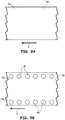
- the bundling article 10 shown in FIGS. 1-5 may be manufactured using a web-based process, such as shown in FIGS. 6A-6C .
- the process may initially involve advancing a web of the material for panel 16, referred to as panel web 38, in a direction A.
- panel web 38 may be unprinted or pre-printed, or may be printed in-line as a step in the bundling article manufacturing process.
- face 26 may be surface treated in the intended regions of bonded portions 24 for the bundling articles 10, such as with a bond-promoting coating.
- a masking material e.g., silicone
- face 26 may be applied to face 26 at the areas outside of the intended regions of bonded portions 24.
- panel web 38 While advancing in the direction A, panel web 38 may reach an aperture cutting station, which cuts panel apertures 30 into panel web 38, such as with a rotary die cutter. The cut out portions of panel web 38 for panel apertures 30 may be collected and recycled.
- elastomer extrusion station which extrudes the elastomer material for elastomer elements 18 and 20 onto panel web to provide elastomer layers 40.
- elastomer layers 40 are three strips that overlay or otherwise cover panel apertures 30.
- panel web 38 may reach one or more additional die cutting stations, which (i) selectively cut elastomer apertures 22 into elastomer layers 40; (ii) selectively kiss-cut and remove excess portions of elastomer layers 40 to define the outer geometries of elastomer elements 18 and 20, (iii) selectively cut panel web 38 to define the outer dimensions of panels 16, thereby producing excess weed 42; and (iv) selectively form perforations at ends 44 and side edges 46 of each bundling article 10.
- the excess materials cut from the web assembly e.g., weed 42
- bundling articles 10 are provided in two rows arranged so that first row 48 is a mirror image of second row 50.
- Ends 44 and side edges 46 are illustrated as boundaries for bundling articles 10, wherein each bundling article 10 comprises a pair of elastomer elements 18 and 20 (each having an stretchable aperture 22).
- ends 44 and side edges 46 may be selectively positioned as boundaries for a bundling article including any number of elastomer elements and apertures.
- ends 44 and side edges 46 may surround a group of six elastomer elements to group six items (not shown) together.
- panel web 38 may be provided with slits to allow a user to pull up a strip of material of panel 16 for use as a handle for the multi-item bundling article (e.g., as a "six-pack" carrier).
- the back side of panel web 38 may include an adhesive backing provided on a release liner.
- adjacent bundling articles 10 may be cut such that they are fully separated from each other for ease of removal from the release liner. After the cutting steps, the resulting web assemblies may be rolled onto spools or provided in sheet form. During use, each bundling article 10 may be separated from the roll or sheet, and used to bundle items, such as bottles 12 and 14, together for handling, storage, shipping, and display.
- the bundling articles 10 may be retained as in roll form wound on a spool or core, where the individual bundling articles 10 are separable by perforations as ends 44 and side edges 46.
- the spool or core with the wound roll may be loaded to an application machine and use in an automated process.
- individual bundling articles 10 may be separated from the roll form by tearing the perforations, and the separated bundling articles 10 may be applied to items (e.g., bottles 12 and 14), as discussed above.
- Bundling article 10 is particularly suitable with the arrangement shown in FIGS. 1-5 , having two elastomer elements 18 and 20, each having single stretchable aperture 22.
- bundling article 10 may include a single elastomer element, or three or more elastomer elements with corresponding stretchable apertures 22.
- each elastomer element may include one stretchable aperture 22, or may include multiple stretchable apertures 22.
- FIG. 7 illustrates an alternative bundling article 10, which also includes tag portion 52 integrally formed with panel 16, and extending laterally from panel 16 via connecting neck 54.
- Suitable materials for tag portion 52 include those discussed above for panel 16, where panel 16 and tag portion 52 may be derived from the same or different materials.
- tag portion 52 includes face 56, which may include indicia 58 to convey information, such as promotional information about the items to be retained by bundling article 10.
- tag portion 52 is illustrated as having a general rectangular geometry, in alternative embodiments, tag portion 52 may have any desired geometry, such as standard geometric shapes (e.g., squares, triangles, etc%), artistic and/or logo-based shapes, and the like. Furthermore, tag portion 52 may extend in any direction from panel 16, and in some embodiments, multiple tag portions 52 may extend from panel 16.
- a line of weakness such as perforation or score line 60 may optionally be included at connecting neck 54 for ease of orientation (e.g., bending) of tag portion 52 relative to panel 16 (either up or down). Line 60 may also optionally allow for ease of detachment of tag portion 52, such as where tag portion 52 may function as a coupon.
- tag portion 52 may be attached to tag portion 52, such as, for example, a magnet 62 on a back surface of tag portion 52, opposite of face 56, where, upon removal, tag portion 52 may serve a refrigerator magnet.
- a layer of adhesive may be provided on face 56 so that a separate product, such as a sample packet, may be adhered to face 56 of tag portion 52.
- a layer of adhesive may be disposed on a back surface of tag portion 52.
- the layer of adhesive may be covered with a release liner that may be removed to expose the adhesive for use (e.g., for use in adhering tag portion 52 to an item being engaged by bundling article 10, to a product sample, or for use by a consumer to adhere tag portion 52 to another surface).
- a release liner that may be removed to expose the adhesive for use (e.g., for use in adhering tag portion 52 to an item being engaged by bundling article 10, to a product sample, or for use by a consumer to adhere tag portion 52 to another surface).
- the bundling article 10 shown in FIG. 7 may be manufactured in a similar manner to the embodiment shown in FIGS. 1-5 .
- the web-based process shown in FIGS. 6A-6C may be modified to accommodate tag portion 52.
- the bundling article 10 shown in FIG. 7 may be produced using a web-based process similar to that shown below in FIGS. 9A-9D .
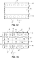
- FIG. 8 illustrates yet another alternative bundling article 10, similar to the embodiment shown in FIG. 7 , where a single elastomer element 64 covers panel 16 and encompasses both apertures 22 (as opposed to a pair of elastomer elements 18 and 20). As further shown, elastomer element 64 may also extend down into connecting neck 54 to define elastomer edge 66.
- the embodied bundling articles 10 of the present disclosure may include at least one elastomer element having at least one bonded portion that is bonded to panel 16, and first and second inner portions that are not bonded to panel 16.
- the at least one elastomer element includes the first and second elastomer elements 18 and 20, which respectively have the first and second bonded portions 24, and the first and second non-bonded or inner portions 28 that overlay panel apertures 30.
- the at least one elastomer element includes a single elastomer element having a single bonded portion extending across panel 16, and the first and second non-bonded or inner portions 28 that overlay panel apertures 30.
- Bundling article 10 of the embodiment shown in FIG. 8 may also be manufactured using a web-based process, such as shown in FIGS. 9A-9D .
- the process may initially involve advancing a web of the material for panel 16, referred to again as panel web 38, in a direction A.
- panel web 38 may be unprinted or pre-printed, or may be printed in-line as a step in the bundling article manufacturing process.
- panel web 38 may be surface treated at the intended locations of faces 26 for panels 16, such as with a bond-promoting coating.
- panel web 38 may reach an aperture cutting station, which cuts panel apertures 30 into panel web 38, such as with a rotary die cutter.
- the cut out portions of panel web 38 for panel apertures 30 may be collected and recycled.
- elastomer layers 40 are two strips that overlay or otherwise cover panel apertures 30.
- panel web 38 may reach one or more additional die cutting stations, which (i) selectively cut apertures 22 into elastomer layers 40; (ii) selectively kiss-cut and remove excess portions of elastomer layers 40 to define the outer geometries of elastomer elements 64, (iii) selectively cut panel web 38 to define the outer dimensions of panels 16, tag portions 52, and connecting necks 54, thereby producing excess weed 42; and (iv) selectively form perforations at tag ends 68 and side edges 70 of each bundling article 10.
- the excess materials cut from the web assembly e.g., weed 42
- FIGS. 10A and 10B illustrate another alternative bundling article 10 for use with two similarly-sized items, such as bottles 72.
- bundling article 10 is similar to the embodiment shown in FIG. 8 , where tag portion 52 is replaced with band 74 that extends from panel 16, and is configured to wrap around the two bottles 72.
- panel 16 may be oriented upside down compared to the embodiments shown in FIGS. 1-5, 7, and 8 .
- elastomer element 64 is located on the underlying side, and the opposing face 76 of panel 16 faces upward.
- band 74 includes a perforation or score line 78 to facilitate a fold thereon.
- band 74 includes a banner area 80 and an elastomer portion 82.
- the banner area 80 wraps around a front and sides of the bundled bottles 72 and may include printing or other indica.
- the elastomer portion 82 is disposed on a back side of band 74 and assists in retaining band 74 snuggly on bottles 72 under elastic tension.
- An elastomer material used for elastomer portion 82 may include the elastomer materials discussed above for elastomer elements 18, 20, and 64.
- the embodied bundling articles 10 of the present disclosure may have a variety of different configurations of panels, apertures, and elastomer elements.
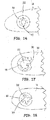
- FIGS. 11-18 illustrate just a few partial top views of panels 16, each having a circular panel aperture 30 and different configurations of elastomer elements 18, thereby resulting in different configurations for stretchable apertures 22 that are not overlaid by the elastomer elements 18. It is contemplated that even more variations are possible by changing the configuration of the aperture in the panel to a configuration other than a circular panel aperture 30.
- FIG. 19 illustrates yet another alternative bundling article 10, which includes panel slits 30a and 30b in lieu of panel apertures 30.
- panel 16 includes four panel slits 30a extending in a cross-pattern, with panel slits 30b extending from the terminus of each panel slit 30a in an arced arrangement.
- panel 16 may include any suitable number of panel slits 30a and 30b at each of elastomer elements 18 and 20.
- Panel slits 30a and 30b may function in a similar manner to panel apertures 30, where items may be inserted through each of panel slits 30a and stretchable apertures 22. However, in this embodiment, panel slits 30a may further assist in restraining the items in stretchable apertures 22.
- Stretchable apertures 22 may be stretched and relaxed to retain items under elastic tension as discussed above, where the dimensions of panel slits 30b effectively function as the perimeters of panel apertures 30 (shown above in FIGS. 1-5 ).
- elastomer portions 18 and 20 each include inner portion 28 that extends inward from bonded portion 24 in the same manner as discussed above. This accordingly limits the stretching of stretchable apertures 22, as discussed above, while also allowing panel slits 30a to mechanically retain the inserted items.
- bundling article 10 of this embodiment may also include tag portion 52 (e.g., as shown in FIGS. 7 and 8 ).
- Bundling article 10 of this embodiment may be manufactured in the same manner as the embodiment shown above in FIGS. 1-6C , where panel slits 30a and 30b are cut in the web prior to applying the elastomer material.
- One processing advantage of this embodiment is that the cores of panel 16, would otherwise be removed if panel apertures 30 were cut out, are no longer present. As such, removal and collection of the panel cores is omitted.
- panel 16 may be cut with a variety of different panel openings, such as panel apertures 30 and/or panel slits 30a and 30b.
- one end of panel 16 may include a panel aperture 30, and the other end may include panel slits 30a and 30b.
- panel opening may refer a panel aperture (e.g., panel aperture 30) and panel slits (e.g., panel slits 30a and 30b).
Landscapes
- Engineering & Computer Science (AREA)
- Mechanical Engineering (AREA)
- General Engineering & Computer Science (AREA)
- Package Frames And Binding Bands (AREA)
- Packages (AREA)
- Details Of Rigid Or Semi-Rigid Containers (AREA)
- Clamps And Clips (AREA)
Claims (15)
- Article de liaison (10) comprenant un panneau (16) définissant une première ouverture de panneau (30) et une seconde ouverture de panneau (30), et au moins un élément élastomérique (18, 20) ; l'article de liaison étant caractérisé en ce que :le ou les éléments élastomériques (18, 20) comprennent :au moins une partie assemblée (24) qui est assemblée au panneau (16) ;une première partie intérieure (28) s'étendant vers l'intérieur à partir de la ou des parties assemblées (24), la première partie intérieure (28) n'étant pas assemblée au panneau (16), et la première partie intérieure (28) recouvrant la première ouverture de panneau (30) et définissant un premier orifice étirable (22) présentant des dimensions qui sont inférieures à des dimensions respectives de la première ouverture de panneau (30) ; etune seconde partie intérieure (28) s'étendant vers l'intérieur à partir de la ou des parties assemblées (24), la seconde partie intérieure (28) n'étant pas assemblée au panneau (16), et la seconde partie intérieure (28) recouvrant la seconde ouverture de panneau (30) et définissant un second orifice étirable (22) présentant des dimensions qui sont inférieures à des dimensions respectives de la seconde ouverture de panneau (30).
- Article de liaison (10) selon la revendication 1, dans lequel la ou les parties assemblées (24) comprennent une première partie assemblée (24) et une seconde partie assemblée (24), et dans lequel le ou les éléments élastomériques (18, 20) comprennent :un premier élément élastomérique (18) comportant la première partie assemblée (24) et la première partie intérieure (28) ; etun second élément élastomérique (20) comportant la seconde partie assemblée (24) et la seconde partie intérieure (28), le second élément élastomérique (20) étant séparé du premier élément élastomérique (18).
- Article de liaison (10) selon la revendication 2, dans lequel le premier élément élastomérique (18) et le second élément élastomérique (20) présentent chacun une géométrie annulaire.
- Article de liaison (10) selon la revendication 1, dans lequel la première ouverture de panneau (30) et la seconde ouverture de panneau (30) comprennent chacune une ouverture de panneau (30) présentant une section transversale essentiellement circulaire.
- Article de liaison (10) selon la revendication 1, dans lequel la première ouverture de panneau (30) et le premier orifice étirable (22) sont essentiellement concentriques, et dans lequel la seconde ouverture de panneau (30) et le second orifice étirable (22) sont essentiellement concentriques.
- Article de liaison (10) selon la revendication 1, dans lequel le panneau (16) est essentiellement non étirable.
- Article de liaison (10) selon la revendication 1, et comprenant en outre une partie formant étiquette (52) s'étendant à partir du panneau (16).
- Article de liaison (10) selon la revendication 1, et comprenant en outre une bande (74) s'étendant à partir du panneau (16).
- Article de liaison (10) selon la revendication 2, dans lequel le premier orifice étirable (22) et le second orifice étirable (22) présentent chacun une section transversale essentiellement circulaire, et dans lequel la première partie intérieure (28) et la seconde partie intérieure (28) sont chacune continues sans aucune fente radiale.
- Procédé d'utilisation d'un article de liaison (10), le procédé comprenant :prévoir l'article de liaison (10) comprenant :un panneau (16) définissant une première ouverture de panneau (30) et une seconde ouverture de panneau (30) ;un premier élément élastomérique (18) assemblé au panneau (16) de telle sorte qu'une partie du premier élément élastomérique (18) recouvre la première ouverture de panneau (30), le premier élément élastomérique (18) définissant un premier orifice étirable (22) ; etun second élément élastomérique (20) assemblé au panneau (16) de telle sorte qu'une partie du second élément élastomérique (20) recouvre la seconde ouverture de panneau (30), le second élément élastomérique (20) définissant un second orifice étirable (22) ;insérer un premier objet (12, 72) à travers la première ouverture de panneau (30) et le premier orifice étirable (22), ceci étirant le premier orifice étirable (22) ;retenir le premier objet (12, 72) inséré dans le premier orifice étirable (22) par le biais de la tension élastique du premier élément élastomérique (18) ;insérer un second objet (14, 72) à travers la seconde ouverture de panneau (30) et le second orifice étirable (22), ceci étirant le second orifice étirable (22) ; etretenir le second objet (14, 72) inséré dans le second orifice étirable (22) par le biais de la tension élastique du second élément élastomérique (20).
- Procédé selon la revendication 10, dans lequel le fait d'insérer le premier objet (12, 72) à travers la première ouverture de panneau (30) n'étire pas la première ouverture de panneau (30), et dans lequel le fait d'insérer le second objet (14, 72) à travers la seconde ouverture de panneau (30) n'étire pas la seconde ouverture de panneau (30).
- Procédé selon la revendication 10, dans lequel le fait de prévoir l'article de liaison (10) comprend le fait de séparer l'article de liaison (10) d'un rouleau composé de multiples articles de liaison (10).
- Procédé selon la revendication 10, et comprenant en outre le fait de suspendre au panneau (16) une partie formant étiquette (52) de l'article de liaison (10).
- Procédé selon la revendication 10, et comprenant en outre :suspendre au panneau (16) une bande (74) de l'article de liaison (10); etenrouler la bande (74) autour du premier objet (72) et du second objet (72).
- Procédé selon la revendication 10, dans lequel le premier orifice étirable (22) présente des dimensions qui sont inférieures à celles de la première ouverture de panneau (30), et dans lequel le second orifice étirable (22) présente des dimensions qui sont inférieures à celles de la seconde ouverture de panneau (30).
Priority Applications (1)
| Application Number | Priority Date | Filing Date | Title |
|---|---|---|---|
| EP17164868.6A EP3222553B1 (fr) | 2013-03-14 | 2014-03-11 | Article pour enliassage des articles entre eux |
Applications Claiming Priority (2)
| Application Number | Priority Date | Filing Date | Title |
|---|---|---|---|
| US201361784458P | 2013-03-14 | 2013-03-14 | |
| PCT/US2014/023071 WO2014150367A1 (fr) | 2013-03-14 | 2014-03-11 | Article pour enliassage des articles entre eux |
Related Child Applications (2)
| Application Number | Title | Priority Date | Filing Date |
|---|---|---|---|
| EP17164868.6A Division EP3222553B1 (fr) | 2013-03-14 | 2014-03-11 | Article pour enliassage des articles entre eux |
| EP17164868.6A Division-Into EP3222553B1 (fr) | 2013-03-14 | 2014-03-11 | Article pour enliassage des articles entre eux |
Publications (2)
| Publication Number | Publication Date |
|---|---|
| EP2969832A1 EP2969832A1 (fr) | 2016-01-20 |
| EP2969832B1 true EP2969832B1 (fr) | 2017-06-28 |
Family
ID=50483502
Family Applications (2)
| Application Number | Title | Priority Date | Filing Date |
|---|---|---|---|
| EP17164868.6A Active EP3222553B1 (fr) | 2013-03-14 | 2014-03-11 | Article pour enliassage des articles entre eux |
| EP14717270.4A Active EP2969832B1 (fr) | 2013-03-14 | 2014-03-11 | Article pour enliassage des articles entre eux |
Family Applications Before (1)
| Application Number | Title | Priority Date | Filing Date |
|---|---|---|---|
| EP17164868.6A Active EP3222553B1 (fr) | 2013-03-14 | 2014-03-11 | Article pour enliassage des articles entre eux |
Country Status (8)
| Country | Link |
|---|---|
| US (1) | US10611538B2 (fr) |
| EP (2) | EP3222553B1 (fr) |
| AU (1) | AU2014237261B2 (fr) |
| CA (1) | CA2899245C (fr) |
| ES (2) | ES2632474T3 (fr) |
| MX (1) | MX360931B (fr) |
| NZ (1) | NZ710410A (fr) |
| WO (1) | WO2014150367A1 (fr) |
Families Citing this family (6)
| Publication number | Priority date | Publication date | Assignee | Title |
|---|---|---|---|---|
| CA2882162C (fr) * | 2012-08-29 | 2018-02-13 | Bedford Industries, Inc. | Etiquettes d'attachement et procedes de fabrication et d'utilisation de ces etiquettes |
| US20140059810A1 (en) * | 2012-08-31 | 2014-03-06 | AKACAS IP Holdings, LLC | Bottle bracelet |
| MX360931B (es) | 2013-03-14 | 2018-11-21 | Bedford Ind Inc | Articulo para enfardar articulos conjuntamente. |
| MX2016016174A (es) | 2014-07-02 | 2017-03-08 | Bedford Ind Inc | Montaje de etiqueta para retener y exhibir productos. |
| WO2019183069A1 (fr) * | 2018-03-20 | 2019-09-26 | Bedford Industries, Inc. | Article de fermeture à élément de fixation auxiliaire |
| USD986048S1 (en) * | 2019-08-19 | 2023-05-16 | Sim Design Limited | Bottle strap |
Family Cites Families (14)
| Publication number | Priority date | Publication date | Assignee | Title |
|---|---|---|---|---|
| US2487109A (en) * | 1946-06-25 | 1949-11-08 | Henry S Deichert | Bottle carrier |
| US2520203A (en) * | 1946-11-09 | 1950-08-29 | Haywa Peter | Bottleholder |
| US3884354A (en) * | 1970-11-16 | 1975-05-20 | Bjorksten Research Lab Inc | Package for bottles |
| NZ225305A (en) * | 1987-07-10 | 1990-09-26 | Mead Corp | Container multipack: encircling elastic band |
| US5706936A (en) * | 1994-06-30 | 1998-01-13 | International Paper | Paperboard bottle carrier |
| US6935491B2 (en) * | 1998-12-24 | 2005-08-30 | Illinois Tool Works Inc. | Film multipackage |
| US7281345B2 (en) | 2004-02-04 | 2007-10-16 | Bedford Industries, Inc. | Merchandise labeling |
| US7510074B2 (en) * | 2004-12-08 | 2009-03-31 | Illinois Tool Works Inc. | Flexible carrier |
| WO2007084119A1 (fr) | 2006-01-17 | 2007-07-26 | Bedford Industries, Inc. | Articles d'etiquetage composites separables en forme de feuilles ou de rouleaux |
| US7836622B1 (en) | 2006-09-28 | 2010-11-23 | Bedford Industries, Inc. | Foldable tag with expandable loop |
| NL1032804C2 (nl) * | 2006-10-17 | 2008-04-22 | Draisma Ind Vormgeving | Druppelvanger en werkwijze. |
| NL1034414C2 (nl) * | 2007-09-21 | 2009-03-24 | Maxi Miliaan Bv | Houder voor het losneembaar bevestigen van een fles aan een ondersteuning. |
| US20090101662A1 (en) * | 2007-10-08 | 2009-04-23 | Marco Leslie S | Multipack for cups and pots |
| MX360931B (es) | 2013-03-14 | 2018-11-21 | Bedford Ind Inc | Articulo para enfardar articulos conjuntamente. |
-
2014
- 2014-03-11 MX MX2015011440A patent/MX360931B/es active IP Right Grant
- 2014-03-11 AU AU2014237261A patent/AU2014237261B2/en active Active
- 2014-03-11 EP EP17164868.6A patent/EP3222553B1/fr active Active
- 2014-03-11 US US14/776,061 patent/US10611538B2/en active Active
- 2014-03-11 CA CA2899245A patent/CA2899245C/fr active Active
- 2014-03-11 ES ES14717270.4T patent/ES2632474T3/es active Active
- 2014-03-11 ES ES17164868T patent/ES2770060T3/es active Active
- 2014-03-11 EP EP14717270.4A patent/EP2969832B1/fr active Active
- 2014-03-11 NZ NZ710410A patent/NZ710410A/en unknown
- 2014-03-11 WO PCT/US2014/023071 patent/WO2014150367A1/fr active Application Filing
Non-Patent Citations (1)
| Title |
|---|
| None * |
Also Published As
| Publication number | Publication date |
|---|---|
| ES2632474T3 (es) | 2017-09-13 |
| US10611538B2 (en) | 2020-04-07 |
| EP3222553B1 (fr) | 2019-12-25 |
| AU2014237261A1 (en) | 2015-08-13 |
| WO2014150367A1 (fr) | 2014-09-25 |
| MX2015011440A (es) | 2016-02-03 |
| MX360931B (es) | 2018-11-21 |
| EP2969832A1 (fr) | 2016-01-20 |
| EP3222553A1 (fr) | 2017-09-27 |
| US20160031621A1 (en) | 2016-02-04 |
| AU2014237261B2 (en) | 2018-03-15 |
| CA2899245A1 (fr) | 2014-09-25 |
| NZ710410A (en) | 2017-10-27 |
| CA2899245C (fr) | 2021-01-05 |
| ES2770060T3 (es) | 2020-06-30 |
Similar Documents
| Publication | Publication Date | Title |
|---|---|---|
| EP2969832B1 (fr) | Article pour enliassage des articles entre eux | |
| US9799237B2 (en) | Labeling article and method of use | |
| US10532868B2 (en) | Tag assembly for retaining and displaying products | |
| US20230368704A1 (en) | Tag Attachment by Shrink Film | |
| US10388192B2 (en) | Flat elastic labeling article | |
| CA2931071C (fr) | Ensemble etiquette a element de fermeture adhesif pour boucle elastomere | |
| US20200226956A1 (en) | Labeling article with encapsulated tag end | |
| JP3992350B2 (ja) | ラベル形成基材 |
Legal Events
| Date | Code | Title | Description |
|---|---|---|---|
| PUAI | Public reference made under article 153(3) epc to a published international application that has entered the european phase |
Free format text: ORIGINAL CODE: 0009012 |
|
| 17P | Request for examination filed |
Effective date: 20150827 |
|
| AK | Designated contracting states |
Kind code of ref document: A1 Designated state(s): AL AT BE BG CH CY CZ DE DK EE ES FI FR GB GR HR HU IE IS IT LI LT LU LV MC MK MT NL NO PL PT RO RS SE SI SK SM TR |
|
| AX | Request for extension of the european patent |
Extension state: BA ME |
|
| RIN1 | Information on inventor provided before grant (corrected) |
Inventor name: WINTZ, TREVOR Inventor name: SCHILLER, DAVID |
|
| DAX | Request for extension of the european patent (deleted) | ||
| 17Q | First examination report despatched |
Effective date: 20160817 |
|
| GRAP | Despatch of communication of intention to grant a patent |
Free format text: ORIGINAL CODE: EPIDOSNIGR1 |
|
| INTG | Intention to grant announced |
Effective date: 20170207 |
|
| GRAS | Grant fee paid |
Free format text: ORIGINAL CODE: EPIDOSNIGR3 |
|
| GRAA | (expected) grant |
Free format text: ORIGINAL CODE: 0009210 |
|
| AK | Designated contracting states |
Kind code of ref document: B1 Designated state(s): AL AT BE BG CH CY CZ DE DK EE ES FI FR GB GR HR HU IE IS IT LI LT LU LV MC MK MT NL NO PL PT RO RS SE SI SK SM TR |
|
| REG | Reference to a national code |
Ref country code: GB Ref legal event code: FG4D |
|
| REG | Reference to a national code |
Ref country code: CH Ref legal event code: EP |
|
| REG | Reference to a national code |
Ref country code: AT Ref legal event code: REF Ref document number: 904626 Country of ref document: AT Kind code of ref document: T Effective date: 20170715 |
|
| REG | Reference to a national code |
Ref country code: IE Ref legal event code: FG4D |
|
| REG | Reference to a national code |
Ref country code: DE Ref legal event code: R096 Ref document number: 602014011232 Country of ref document: DE |
|
| REG | Reference to a national code |
Ref country code: CH Ref legal event code: NV Representative=s name: OFFICE ERNEST T. FREYLINGER S.A., CH |
|
| REG | Reference to a national code |
Ref country code: ES Ref legal event code: FG2A Ref document number: 2632474 Country of ref document: ES Kind code of ref document: T3 Effective date: 20170913 |
|
| REG | Reference to a national code |
Ref country code: NL Ref legal event code: FP |
|
| PG25 | Lapsed in a contracting state [announced via postgrant information from national office to epo] |
Ref country code: HR Free format text: LAPSE BECAUSE OF FAILURE TO SUBMIT A TRANSLATION OF THE DESCRIPTION OR TO PAY THE FEE WITHIN THE PRESCRIBED TIME-LIMIT Effective date: 20170628 Ref country code: LT Free format text: LAPSE BECAUSE OF FAILURE TO SUBMIT A TRANSLATION OF THE DESCRIPTION OR TO PAY THE FEE WITHIN THE PRESCRIBED TIME-LIMIT Effective date: 20170628 Ref country code: GR Free format text: LAPSE BECAUSE OF FAILURE TO SUBMIT A TRANSLATION OF THE DESCRIPTION OR TO PAY THE FEE WITHIN THE PRESCRIBED TIME-LIMIT Effective date: 20170929 Ref country code: FI Free format text: LAPSE BECAUSE OF FAILURE TO SUBMIT A TRANSLATION OF THE DESCRIPTION OR TO PAY THE FEE WITHIN THE PRESCRIBED TIME-LIMIT Effective date: 20170628 Ref country code: NO Free format text: LAPSE BECAUSE OF FAILURE TO SUBMIT A TRANSLATION OF THE DESCRIPTION OR TO PAY THE FEE WITHIN THE PRESCRIBED TIME-LIMIT Effective date: 20170928 |
|
| REG | Reference to a national code |
Ref country code: LT Ref legal event code: MG4D |
|
| PG25 | Lapsed in a contracting state [announced via postgrant information from national office to epo] |
Ref country code: BG Free format text: LAPSE BECAUSE OF FAILURE TO SUBMIT A TRANSLATION OF THE DESCRIPTION OR TO PAY THE FEE WITHIN THE PRESCRIBED TIME-LIMIT Effective date: 20170928 Ref country code: SE Free format text: LAPSE BECAUSE OF FAILURE TO SUBMIT A TRANSLATION OF THE DESCRIPTION OR TO PAY THE FEE WITHIN THE PRESCRIBED TIME-LIMIT Effective date: 20170628 Ref country code: LV Free format text: LAPSE BECAUSE OF FAILURE TO SUBMIT A TRANSLATION OF THE DESCRIPTION OR TO PAY THE FEE WITHIN THE PRESCRIBED TIME-LIMIT Effective date: 20170628 Ref country code: RS Free format text: LAPSE BECAUSE OF FAILURE TO SUBMIT A TRANSLATION OF THE DESCRIPTION OR TO PAY THE FEE WITHIN THE PRESCRIBED TIME-LIMIT Effective date: 20170628 |
|
| PG25 | Lapsed in a contracting state [announced via postgrant information from national office to epo] |
Ref country code: SK Free format text: LAPSE BECAUSE OF FAILURE TO SUBMIT A TRANSLATION OF THE DESCRIPTION OR TO PAY THE FEE WITHIN THE PRESCRIBED TIME-LIMIT Effective date: 20170628 Ref country code: EE Free format text: LAPSE BECAUSE OF FAILURE TO SUBMIT A TRANSLATION OF THE DESCRIPTION OR TO PAY THE FEE WITHIN THE PRESCRIBED TIME-LIMIT Effective date: 20170628 Ref country code: CZ Free format text: LAPSE BECAUSE OF FAILURE TO SUBMIT A TRANSLATION OF THE DESCRIPTION OR TO PAY THE FEE WITHIN THE PRESCRIBED TIME-LIMIT Effective date: 20170628 Ref country code: RO Free format text: LAPSE BECAUSE OF FAILURE TO SUBMIT A TRANSLATION OF THE DESCRIPTION OR TO PAY THE FEE WITHIN THE PRESCRIBED TIME-LIMIT Effective date: 20170628 |
|
| PG25 | Lapsed in a contracting state [announced via postgrant information from national office to epo] |
Ref country code: PL Free format text: LAPSE BECAUSE OF FAILURE TO SUBMIT A TRANSLATION OF THE DESCRIPTION OR TO PAY THE FEE WITHIN THE PRESCRIBED TIME-LIMIT Effective date: 20170628 Ref country code: SM Free format text: LAPSE BECAUSE OF FAILURE TO SUBMIT A TRANSLATION OF THE DESCRIPTION OR TO PAY THE FEE WITHIN THE PRESCRIBED TIME-LIMIT Effective date: 20170628 Ref country code: IS Free format text: LAPSE BECAUSE OF FAILURE TO SUBMIT A TRANSLATION OF THE DESCRIPTION OR TO PAY THE FEE WITHIN THE PRESCRIBED TIME-LIMIT Effective date: 20171028 |
|
| REG | Reference to a national code |
Ref country code: FR Ref legal event code: PLFP Year of fee payment: 5 |
|
| REG | Reference to a national code |
Ref country code: DE Ref legal event code: R097 Ref document number: 602014011232 Country of ref document: DE |
|
| PG25 | Lapsed in a contracting state [announced via postgrant information from national office to epo] |
Ref country code: DK Free format text: LAPSE BECAUSE OF FAILURE TO SUBMIT A TRANSLATION OF THE DESCRIPTION OR TO PAY THE FEE WITHIN THE PRESCRIBED TIME-LIMIT Effective date: 20170628 |
|
| PLBE | No opposition filed within time limit |
Free format text: ORIGINAL CODE: 0009261 |
|
| STAA | Information on the status of an ep patent application or granted ep patent |
Free format text: STATUS: NO OPPOSITION FILED WITHIN TIME LIMIT |
|
| 26N | No opposition filed |
Effective date: 20180329 |
|
| PG25 | Lapsed in a contracting state [announced via postgrant information from national office to epo] |
Ref country code: SI Free format text: LAPSE BECAUSE OF FAILURE TO SUBMIT A TRANSLATION OF THE DESCRIPTION OR TO PAY THE FEE WITHIN THE PRESCRIBED TIME-LIMIT Effective date: 20170628 |
|
| PG25 | Lapsed in a contracting state [announced via postgrant information from national office to epo] |
Ref country code: MC Free format text: LAPSE BECAUSE OF FAILURE TO SUBMIT A TRANSLATION OF THE DESCRIPTION OR TO PAY THE FEE WITHIN THE PRESCRIBED TIME-LIMIT Effective date: 20170628 |
|
| REG | Reference to a national code |
Ref country code: BE Ref legal event code: MM Effective date: 20180331 |
|
| PG25 | Lapsed in a contracting state [announced via postgrant information from national office to epo] |
Ref country code: LU Free format text: LAPSE BECAUSE OF NON-PAYMENT OF DUE FEES Effective date: 20180311 |
|
| PG25 | Lapsed in a contracting state [announced via postgrant information from national office to epo] |
Ref country code: BE Free format text: LAPSE BECAUSE OF NON-PAYMENT OF DUE FEES Effective date: 20180331 |
|
| PG25 | Lapsed in a contracting state [announced via postgrant information from national office to epo] |
Ref country code: MT Free format text: LAPSE BECAUSE OF NON-PAYMENT OF DUE FEES Effective date: 20180311 |
|
| PG25 | Lapsed in a contracting state [announced via postgrant information from national office to epo] |
Ref country code: TR Free format text: LAPSE BECAUSE OF FAILURE TO SUBMIT A TRANSLATION OF THE DESCRIPTION OR TO PAY THE FEE WITHIN THE PRESCRIBED TIME-LIMIT Effective date: 20170628 |
|
| PG25 | Lapsed in a contracting state [announced via postgrant information from national office to epo] |
Ref country code: PT Free format text: LAPSE BECAUSE OF FAILURE TO SUBMIT A TRANSLATION OF THE DESCRIPTION OR TO PAY THE FEE WITHIN THE PRESCRIBED TIME-LIMIT Effective date: 20170628 |
|
| PG25 | Lapsed in a contracting state [announced via postgrant information from national office to epo] |
Ref country code: MK Free format text: LAPSE BECAUSE OF NON-PAYMENT OF DUE FEES Effective date: 20170628 Ref country code: HU Free format text: LAPSE BECAUSE OF FAILURE TO SUBMIT A TRANSLATION OF THE DESCRIPTION OR TO PAY THE FEE WITHIN THE PRESCRIBED TIME-LIMIT; INVALID AB INITIO Effective date: 20140311 Ref country code: CY Free format text: LAPSE BECAUSE OF FAILURE TO SUBMIT A TRANSLATION OF THE DESCRIPTION OR TO PAY THE FEE WITHIN THE PRESCRIBED TIME-LIMIT Effective date: 20170628 |
|
| PG25 | Lapsed in a contracting state [announced via postgrant information from national office to epo] |
Ref country code: AL Free format text: LAPSE BECAUSE OF FAILURE TO SUBMIT A TRANSLATION OF THE DESCRIPTION OR TO PAY THE FEE WITHIN THE PRESCRIBED TIME-LIMIT Effective date: 20170628 |
|
| REG | Reference to a national code |
Ref country code: AT Ref legal event code: UEP Ref document number: 904626 Country of ref document: AT Kind code of ref document: T Effective date: 20170628 |
|
| PGFP | Annual fee paid to national office [announced via postgrant information from national office to epo] |
Ref country code: IE Payment date: 20230327 Year of fee payment: 10 Ref country code: FR Payment date: 20230327 Year of fee payment: 10 Ref country code: AT Payment date: 20230221 Year of fee payment: 10 |
|
| PGFP | Annual fee paid to national office [announced via postgrant information from national office to epo] |
Ref country code: IT Payment date: 20230321 Year of fee payment: 10 Ref country code: GB Payment date: 20230327 Year of fee payment: 10 Ref country code: DE Payment date: 20230329 Year of fee payment: 10 |
|
| PGFP | Annual fee paid to national office [announced via postgrant information from national office to epo] |
Ref country code: NL Payment date: 20230326 Year of fee payment: 10 |
|
| PGFP | Annual fee paid to national office [announced via postgrant information from national office to epo] |
Ref country code: ES Payment date: 20230403 Year of fee payment: 10 Ref country code: CH Payment date: 20230402 Year of fee payment: 10 |