EP2968916B1 - Dispositif médical ayant une fusion à capteurs multiples - Google Patents
Dispositif médical ayant une fusion à capteurs multiples Download PDFInfo
- Publication number
- EP2968916B1 EP2968916B1 EP14712509.0A EP14712509A EP2968916B1 EP 2968916 B1 EP2968916 B1 EP 2968916B1 EP 14712509 A EP14712509 A EP 14712509A EP 2968916 B1 EP2968916 B1 EP 2968916B1
- Authority
- EP
- European Patent Office
- Prior art keywords
- signal
- circuit
- device parameter
- metric
- value
- Prior art date
- Legal status (The legal status is an assumption and is not a legal conclusion. Google has not performed a legal analysis and makes no representation as to the accuracy of the status listed.)
- Active
Links
- 230000004927 fusion Effects 0.000 title claims description 29
- 230000000638 stimulation Effects 0.000 claims description 103
- 239000013598 vector Substances 0.000 claims description 64
- 230000004044 response Effects 0.000 claims description 53
- 230000035945 sensitivity Effects 0.000 claims description 49
- 210000002216 heart Anatomy 0.000 claims description 47
- 238000005259 measurement Methods 0.000 claims description 47
- 230000008859 change Effects 0.000 claims description 19
- 239000011159 matrix material Substances 0.000 claims description 15
- 230000015654 memory Effects 0.000 claims description 15
- 230000004936 stimulating effect Effects 0.000 claims description 7
- 230000005236 sound signal Effects 0.000 claims description 6
- 238000002560 therapeutic procedure Methods 0.000 description 35
- 238000000034 method Methods 0.000 description 34
- 238000009125 cardiac resynchronization therapy Methods 0.000 description 21
- 230000002861 ventricular Effects 0.000 description 20
- 210000005240 left ventricle Anatomy 0.000 description 19
- 210000005241 right ventricle Anatomy 0.000 description 16
- 239000008280 blood Substances 0.000 description 12
- 210000004369 blood Anatomy 0.000 description 12
- 238000012360 testing method Methods 0.000 description 12
- 230000001746 atrial effect Effects 0.000 description 10
- 210000005242 cardiac chamber Anatomy 0.000 description 10
- 230000000747 cardiac effect Effects 0.000 description 8
- 206010007559 Cardiac failure congestive Diseases 0.000 description 7
- 206010019280 Heart failures Diseases 0.000 description 7
- 230000004872 arterial blood pressure Effects 0.000 description 7
- 230000029058 respiratory gaseous exchange Effects 0.000 description 7
- 230000006870 function Effects 0.000 description 6
- 210000005245 right atrium Anatomy 0.000 description 6
- 230000001537 neural effect Effects 0.000 description 5
- 210000001147 pulmonary artery Anatomy 0.000 description 5
- 230000004913 activation Effects 0.000 description 4
- 238000013194 cardioversion Methods 0.000 description 4
- 238000004891 communication Methods 0.000 description 4
- 230000008602 contraction Effects 0.000 description 4
- 230000007423 decrease Effects 0.000 description 4
- 210000005246 left atrium Anatomy 0.000 description 4
- 210000005036 nerve Anatomy 0.000 description 4
- OIRCZHKOHJUHAC-SIUGBPQLSA-N Ala-Val-Asp-Tyr Chemical compound C[C@H](N)C(=O)N[C@@H](C(C)C)C(=O)N[C@@H](CC(O)=O)C(=O)N[C@H](C(O)=O)CC1=CC=C(O)C=C1 OIRCZHKOHJUHAC-SIUGBPQLSA-N 0.000 description 3
- QVGXLLKOCUKJST-UHFFFAOYSA-N atomic oxygen Chemical compound [O] QVGXLLKOCUKJST-UHFFFAOYSA-N 0.000 description 3
- 239000004020 conductor Substances 0.000 description 3
- 230000000694 effects Effects 0.000 description 3
- 238000007726 management method Methods 0.000 description 3
- 238000012544 monitoring process Methods 0.000 description 3
- 229910052760 oxygen Inorganic materials 0.000 description 3
- 239000001301 oxygen Substances 0.000 description 3
- 230000008569 process Effects 0.000 description 3
- 238000005086 pumping Methods 0.000 description 3
- 239000000126 substance Substances 0.000 description 3
- 206010061818 Disease progression Diseases 0.000 description 2
- 238000013528 artificial neural network Methods 0.000 description 2
- 108091008698 baroreceptors Proteins 0.000 description 2
- 230000036772 blood pressure Effects 0.000 description 2
- 230000036760 body temperature Effects 0.000 description 2
- 230000037396 body weight Effects 0.000 description 2
- 238000003066 decision tree Methods 0.000 description 2
- 230000005750 disease progression Effects 0.000 description 2
- 239000003814 drug Substances 0.000 description 2
- 229940079593 drug Drugs 0.000 description 2
- 238000013213 extrapolation Methods 0.000 description 2
- 230000036541 health Effects 0.000 description 2
- 230000004217 heart function Effects 0.000 description 2
- 238000002347 injection Methods 0.000 description 2
- 239000007924 injection Substances 0.000 description 2
- 238000012417 linear regression Methods 0.000 description 2
- 238000007477 logistic regression Methods 0.000 description 2
- 239000000203 mixture Substances 0.000 description 2
- 230000002093 peripheral effect Effects 0.000 description 2
- 230000037081 physical activity Effects 0.000 description 2
- 230000035790 physiological processes and functions Effects 0.000 description 2
- 230000036544 posture Effects 0.000 description 2
- 210000001774 pressoreceptor Anatomy 0.000 description 2
- 230000033764 rhythmic process Effects 0.000 description 2
- 238000001228 spectrum Methods 0.000 description 2
- 230000001225 therapeutic effect Effects 0.000 description 2
- 210000001519 tissue Anatomy 0.000 description 2
- 210000002620 vena cava superior Anatomy 0.000 description 2
- 208000006029 Cardiomegaly Diseases 0.000 description 1
- 208000017667 Chronic Disease Diseases 0.000 description 1
- 241001632160 Dismorphiinae Species 0.000 description 1
- 230000009471 action Effects 0.000 description 1
- 230000006978 adaptation Effects 0.000 description 1
- 230000035581 baroreflex Effects 0.000 description 1
- 230000005540 biological transmission Effects 0.000 description 1
- 238000001815 biotherapy Methods 0.000 description 1
- 230000002051 biphasic effect Effects 0.000 description 1
- 238000009530 blood pressure measurement Methods 0.000 description 1
- 238000004590 computer program Methods 0.000 description 1
- 210000003748 coronary sinus Anatomy 0.000 description 1
- 230000001186 cumulative effect Effects 0.000 description 1
- 230000003111 delayed effect Effects 0.000 description 1
- 230000001419 dependent effect Effects 0.000 description 1
- 238000001514 detection method Methods 0.000 description 1
- 238000002405 diagnostic procedure Methods 0.000 description 1
- 230000035487 diastolic blood pressure Effects 0.000 description 1
- 201000010099 disease Diseases 0.000 description 1
- 208000037265 diseases, disorders, signs and symptoms Diseases 0.000 description 1
- 238000012377 drug delivery Methods 0.000 description 1
- 238000009472 formulation Methods 0.000 description 1
- 230000005802 health problem Effects 0.000 description 1
- 230000003862 health status Effects 0.000 description 1
- 210000002837 heart atrium Anatomy 0.000 description 1
- 230000006872 improvement Effects 0.000 description 1
- 230000001939 inductive effect Effects 0.000 description 1
- 230000005226 mechanical processes and functions Effects 0.000 description 1
- 230000000877 morphologic effect Effects 0.000 description 1
- 210000004165 myocardium Anatomy 0.000 description 1
- 230000003287 optical effect Effects 0.000 description 1
- 238000007500 overflow downdraw method Methods 0.000 description 1
- 230000004043 responsiveness Effects 0.000 description 1
- 230000035488 systolic blood pressure Effects 0.000 description 1
- 210000003462 vein Anatomy 0.000 description 1
Images


Classifications
-
- A—HUMAN NECESSITIES
- A61—MEDICAL OR VETERINARY SCIENCE; HYGIENE
- A61N—ELECTROTHERAPY; MAGNETOTHERAPY; RADIATION THERAPY; ULTRASOUND THERAPY
- A61N1/00—Electrotherapy; Circuits therefor
- A61N1/02—Details
- A61N1/04—Electrodes
- A61N1/05—Electrodes for implantation or insertion into the body, e.g. heart electrode
- A61N1/056—Transvascular endocardial electrode systems
-
- A—HUMAN NECESSITIES
- A61—MEDICAL OR VETERINARY SCIENCE; HYGIENE
- A61N—ELECTROTHERAPY; MAGNETOTHERAPY; RADIATION THERAPY; ULTRASOUND THERAPY
- A61N1/00—Electrotherapy; Circuits therefor
- A61N1/18—Applying electric currents by contact electrodes
- A61N1/32—Applying electric currents by contact electrodes alternating or intermittent currents
- A61N1/36—Applying electric currents by contact electrodes alternating or intermittent currents for stimulation
- A61N1/3605—Implantable neurostimulators for stimulating central or peripheral nerve system
- A61N1/36128—Control systems
- A61N1/36135—Control systems using physiological parameters
- A61N1/36139—Control systems using physiological parameters with automatic adjustment
-
- A—HUMAN NECESSITIES
- A61—MEDICAL OR VETERINARY SCIENCE; HYGIENE
- A61N—ELECTROTHERAPY; MAGNETOTHERAPY; RADIATION THERAPY; ULTRASOUND THERAPY
- A61N1/00—Electrotherapy; Circuits therefor
- A61N1/18—Applying electric currents by contact electrodes
- A61N1/32—Applying electric currents by contact electrodes alternating or intermittent currents
- A61N1/36—Applying electric currents by contact electrodes alternating or intermittent currents for stimulation
- A61N1/362—Heart stimulators
- A61N1/3625—External stimulators
-
- A—HUMAN NECESSITIES
- A61—MEDICAL OR VETERINARY SCIENCE; HYGIENE
- A61N—ELECTROTHERAPY; MAGNETOTHERAPY; RADIATION THERAPY; ULTRASOUND THERAPY
- A61N1/00—Electrotherapy; Circuits therefor
- A61N1/18—Applying electric currents by contact electrodes
- A61N1/32—Applying electric currents by contact electrodes alternating or intermittent currents
- A61N1/36—Applying electric currents by contact electrodes alternating or intermittent currents for stimulation
- A61N1/362—Heart stimulators
- A61N1/3627—Heart stimulators for treating a mechanical deficiency of the heart, e.g. congestive heart failure or cardiomyopathy
-
- A—HUMAN NECESSITIES
- A61—MEDICAL OR VETERINARY SCIENCE; HYGIENE
- A61N—ELECTROTHERAPY; MAGNETOTHERAPY; RADIATION THERAPY; ULTRASOUND THERAPY
- A61N1/00—Electrotherapy; Circuits therefor
- A61N1/18—Applying electric currents by contact electrodes
- A61N1/32—Applying electric currents by contact electrodes alternating or intermittent currents
- A61N1/36—Applying electric currents by contact electrodes alternating or intermittent currents for stimulation
- A61N1/362—Heart stimulators
- A61N1/365—Heart stimulators controlled by a physiological parameter, e.g. heart potential
- A61N1/36514—Heart stimulators controlled by a physiological parameter, e.g. heart potential controlled by a physiological quantity other than heart potential, e.g. blood pressure
-
- A—HUMAN NECESSITIES
- A61—MEDICAL OR VETERINARY SCIENCE; HYGIENE
- A61N—ELECTROTHERAPY; MAGNETOTHERAPY; RADIATION THERAPY; ULTRASOUND THERAPY
- A61N1/00—Electrotherapy; Circuits therefor
- A61N1/18—Applying electric currents by contact electrodes
- A61N1/32—Applying electric currents by contact electrodes alternating or intermittent currents
- A61N1/36—Applying electric currents by contact electrodes alternating or intermittent currents for stimulation
- A61N1/362—Heart stimulators
- A61N1/365—Heart stimulators controlled by a physiological parameter, e.g. heart potential
- A61N1/36585—Heart stimulators controlled by a physiological parameter, e.g. heart potential controlled by two or more physical parameters
-
- A—HUMAN NECESSITIES
- A61—MEDICAL OR VETERINARY SCIENCE; HYGIENE
- A61N—ELECTROTHERAPY; MAGNETOTHERAPY; RADIATION THERAPY; ULTRASOUND THERAPY
- A61N1/00—Electrotherapy; Circuits therefor
- A61N1/18—Applying electric currents by contact electrodes
- A61N1/32—Applying electric currents by contact electrodes alternating or intermittent currents
- A61N1/36—Applying electric currents by contact electrodes alternating or intermittent currents for stimulation
- A61N1/362—Heart stimulators
- A61N1/365—Heart stimulators controlled by a physiological parameter, e.g. heart potential
- A61N1/368—Heart stimulators controlled by a physiological parameter, e.g. heart potential comprising more than one electrode co-operating with different heart regions
- A61N1/3682—Heart stimulators controlled by a physiological parameter, e.g. heart potential comprising more than one electrode co-operating with different heart regions with a variable atrioventricular delay
-
- A—HUMAN NECESSITIES
- A61—MEDICAL OR VETERINARY SCIENCE; HYGIENE
- A61N—ELECTROTHERAPY; MAGNETOTHERAPY; RADIATION THERAPY; ULTRASOUND THERAPY
- A61N1/00—Electrotherapy; Circuits therefor
- A61N1/18—Applying electric currents by contact electrodes
- A61N1/32—Applying electric currents by contact electrodes alternating or intermittent currents
- A61N1/36—Applying electric currents by contact electrodes alternating or intermittent currents for stimulation
- A61N1/362—Heart stimulators
- A61N1/37—Monitoring; Protecting
- A61N1/3702—Physiological parameters
- A61N1/3704—Circuits specially adapted therefor, e.g. for sensitivity control
-
- A—HUMAN NECESSITIES
- A61—MEDICAL OR VETERINARY SCIENCE; HYGIENE
- A61N—ELECTROTHERAPY; MAGNETOTHERAPY; RADIATION THERAPY; ULTRASOUND THERAPY
- A61N1/00—Electrotherapy; Circuits therefor
- A61N1/18—Applying electric currents by contact electrodes
- A61N1/32—Applying electric currents by contact electrodes alternating or intermittent currents
- A61N1/36—Applying electric currents by contact electrodes alternating or intermittent currents for stimulation
- A61N1/362—Heart stimulators
- A61N1/365—Heart stimulators controlled by a physiological parameter, e.g. heart potential
- A61N1/368—Heart stimulators controlled by a physiological parameter, e.g. heart potential comprising more than one electrode co-operating with different heart regions
- A61N1/3684—Heart stimulators controlled by a physiological parameter, e.g. heart potential comprising more than one electrode co-operating with different heart regions for stimulating the heart at multiple sites of the ventricle or the atrium
- A61N1/36842—Multi-site stimulation in the same chamber
-
- A—HUMAN NECESSITIES
- A61—MEDICAL OR VETERINARY SCIENCE; HYGIENE
- A61N—ELECTROTHERAPY; MAGNETOTHERAPY; RADIATION THERAPY; ULTRASOUND THERAPY
- A61N1/00—Electrotherapy; Circuits therefor
- A61N1/18—Applying electric currents by contact electrodes
- A61N1/32—Applying electric currents by contact electrodes alternating or intermittent currents
- A61N1/36—Applying electric currents by contact electrodes alternating or intermittent currents for stimulation
- A61N1/362—Heart stimulators
- A61N1/365—Heart stimulators controlled by a physiological parameter, e.g. heart potential
- A61N1/368—Heart stimulators controlled by a physiological parameter, e.g. heart potential comprising more than one electrode co-operating with different heart regions
- A61N1/3684—Heart stimulators controlled by a physiological parameter, e.g. heart potential comprising more than one electrode co-operating with different heart regions for stimulating the heart at multiple sites of the ventricle or the atrium
- A61N1/36843—Bi-ventricular stimulation
Definitions
- This document relates generally to medical devices, and more particularly, to systems, devices and methods for improving a device therapy using multiple sensor metrics.
- CHF Congestive heart failure
- CHF is usually a chronic condition, but can occur suddenly. It can affect the left heart, right heart or both sides of the heart. If CHF affects the left ventricle, signals that control the left ventricular contraction are delayed, and the left and right ventricles do not contract simultaneously. Non-simultaneous contractions of the left and right ventricles further decrease the pumping efficiency of the heart.
- CHF can be treated by cardiac pacing therapy.
- Pacing therapy to promote synchronization of heart chamber contractions for improved cardiac function is generally referred to as cardiac resynchronization therapy (CRT).
- Ambulatory medical devices such as cardiac pacemakers are capable of delivering CRT by pacing multiple heart chambers. Some ambulatory medical devices can pace the heart chambers in a sequence that causes the heart chambers to contract in synchrony, thereby increasing the pumping power of the heart and delivering more blood to the peripheral tissues of the body.
- a biventricular pacing therapy can be used to resynchronize the left and right ventricles. Bi-atrial pacing or pacing of all four heart chambers can also be used.
- Improving the CRT therapy by determining desired CRT parameters involves determining desired pacing parameters, such as intervals between pacing pulses delivered to various heart chambers that provide effective CRT delivery. Due to the variation across patient population in their responses to CRT as well as the within-patient variation in optimal CRT setting as a result of, for example, changes in the patient's activity level, disease progression, medication, and general health condition, the patient response to CRT vary; and the therapy parameter need to be timely adjusted to provide and maintain desired cardiac function to the patient.
- the present inventors have recognized that there remains a considerable need of devices and methods that can automatically improve the device therapy by properly setting the CRT parameters on an individualized basis
- Document US 2010/274141 discloses an implantable medical device according to the preamble of claim 1.
- an ambulatory medical device can receive one or more physiologic signals such as from a physiologic sensor and generate two or more signal metrics from the physiologic signals.
- the ambulatory medical device can include a device parameter adjustment circuit configured to determine a desired value for a device parameter, such as a timing parameter which can be used to control the delivery of CRT pacing to various heart chambers using information fusion.
- the device parameter adjustment circuit includes a sensitivity calculator circuit, a variability calculator circuit, and a covariability calculator circuit.
- the sensitivity calculator circuit is configured to determine for at least two of the two or more signal metrics a respective sensitivity to a perturbation to the device parameter in response to stimulations.
- the variability calculator circuit can be configured to determine for at least two of the two or more signal metrics a respective variability in response to the stimulations.
- the covariability calculator circuit can be configured to determine a covariability between at least two of the two or more signal metrics in response to the stimulations.
- An information fusion circuit can determine the desired device parameter value using one or more of the sensitivity, the variability, or the covariability.
- a controller circuit can program stimulations using the desired device parameter value, and a stimulation generation circuit can generate the programmed stimulations and deliver the stimulations to one or more target sites.
- a method can include sensing one or more physiologic signals and generating two or more signal metrics from the physiologic signals.
- the method can include calculating a sensitivity of the signal metrics in response to stimulation with a perturbation to the device parameter, a variability of the signal metrics in response to the stimulation with a specified device parameter, and a covariability between two or more signal metrics in response to the stimulation with a specified device parameter.
- the method can then use one or more of the sensitivity, the variability, or the covariability to determine a desired value for the device parameter, such as a timing parameter which can be used to control the delivery of CRT pacing to various heart chambers.
- the method includes generating stimulations according to the desired value for the device parameter and delivering the stimulations the target sites.
- Another method can include sensing one or more physiologic signals and generating two or more signal metrics from the physiologic signals, and determine a target directional vector using the difference between a first signal metric vector in response to stimulation when the device parameter is set to a first value, and a second signal metric vector in response to stimulation when the device parameter is set to a second value.
- Each signal metric vector comprises values of the two or more signal metrics measured during the respective stimulation.
- One of the first value or the second value of the device parameter includes a sub-optimal value.
- the method can construct a test signal metric vector in response to stimulation when the device parameter is set to a candidate value, and compute a projection of the test signal metric vector onto the target directional vector. When the projection meets a convergence criterion, the candidate value is determined to be a desired device parameter value.
- the invention is defined by the device of independent claim 1. Preferred embodiments are defined by the dependent claims. All disclosed methods are merely exemplary and do not fall within the scope of the present invention.
- the device therapy can include cardiac pacing therapy provided by an implantable medical device such as a pacemaker, an implantable cardioverter-defibrillator (ICD), or a cardiac resynchronization therapy (CRT) device.
- the improvement of the cardiac pacing therapy can include determining a desired value for a relative timing between a first event in a heart chamber and a second event in a different heart chamber, such as intervals between pacing pulses delivered to atria and ventricles that provide effective CRT delivery.
- the present document discussed methods and devices for improving the device parameters using multiple sensor metrics and information fusion.
- the methods and devices described herein can also be applicable to improving other device functions pertaining to an implantable medical device, including such as pacing therapy, defibrillation therapy, neural stimulation therapy, and patient diagnostics and stratifying a patient's risk of developing a disease or a condition, or to monitoring a patient's health status or response to a medical intervention.
- FIG. 1 illustrates an example of a Cardiac Rhythm Management (CRM) system 100 and portions of an environment in which the CRM system 100 can operate.
- the CRM system 100 can include an ambulatory medical device, such as an implantable medical device (IMD) 110 that can be electrically coupled to a heart 105 such as through one or more leads 108A-C, and an external system 120 that can communicate with the IMD 110 such as via a communication link 103.
- the IMD 110 can include an implantable cardiac device such as a pacemaker, an implantable cardioverter-defibrillator (ICD), or a cardiac resynchronization therapy (CRT) device.
- ICD implantable cardioverter-defibrillator
- CRT cardiac resynchronization therapy
- the IMD 110 can include one or more monitoring or therapeutic devices such as a subcutaneously implanted device, a wearable external device, a neural stimulator, a drug delivery device, a biological therapy device, or one or more other ambulatory medical devices.
- the IMD 110 can be coupled to, or can be substituted by a monitoring medical device such as a bedside or other external monitor.
- the IMD 110 can include a hermetically sealed can 112 that can house an electronic circuit that can sense a physiologic signal in the heart 105 and can deliver one or more therapeutic electrical stimulations to a target region, such as in the heart, such as through one or more leads 108A-C.
- the CRM system 100 can include only one lead such as 108B, or can include two leads such as 108A and 108B.
- the lead 108A can include a proximal end that can be configured to be connected to IMD 110 and a distal end that can be configured to be placed at a target location such as in the right atrium (RA) 131 of the heart 105.
- the lead 108A can have a first pacing-sensing electrode 141 that can be located at or near its distal end, and a second pacing-sensing electrode 142 that can be located at or near the electrode 141.
- the electrodes 141 and 142 can be electrically connected to the IMD 110 such as via separate conductors in the lead 108A, such as to allow for sensing of the right atrial activity and optional delivery of atrial pacing pulses.
- the lead 108B can be a defibrillation lead that can include a proximal end that can be connected to IMD 110 and a distal end that can be placed at a target location such as in the right ventricle (RV) 132 of heart 105.
- the lead 108B can have a first pacing-sensing electrode 152 that can be located at distal end, a second pacing-sensing electrode 153 that can be located near the electrode 152, a first defibrillation coil electrode 154 that can be located near the electrode 153, and a second defibrillation coil electrode 155 that can be located at a distance from the distal end such as for superior vena cava (SVC) placement.
- SVC superior vena cava
- the electrodes 152 through 155 can be electrically connected to the IMD 110 such as via separate conductors in the lead 108B.
- the electrodes 152 and 153 can allow for sensing of a ventricular electrogram (EGM) and can optionally allow delivery of one or more ventricular pacing pulses, and electrodes 154 and 155 can allow for delivery of one or more ventricular cardioversion/defibrillation pulses.
- the lead 108B can include only three electrodes 152, 154 and 155.
- the electrodes 152 and 154 can be used for sensing or delivery of one or more ventricular pacing pulses, and the electrodes 154 and 155 can be used for delivery of one or more ventricular cardioversion or defibrillation pulses.
- the lead 108C can include a proximal end that can be connected to the IMD 110 and a distal end that can be configured to be placed at a target location such as in a left ventricle (LV) 134 of the heart 105.
- the lead 108C can be implanted through the coronary sinus 133 and can be placed in a coronary vein over the LV such as to allow for delivery of one or more pacing pulses to the LV.
- the lead 108C can include an electrode 161 that can be located at a distal end of the lead 108C and another electrode 162 that can be located near the electrode 161.
- the electrodes 161 and 162 can be electrically connected to the IMD 110 such as via separate conductors in the lead 108C such as to allow for sensing of the LV EGM and optionally allow delivery of one or more resynchronization pacing pulses from the LV.
- the IMD 110 can include an electronic circuit that can sense a physiologic signal.
- the physiologic signal can include a EGM or a signal representing mechanical function of the heart 105.
- the hermetically sealed can 112 can function as an electrode such as for sensing or pulse delivery.
- an electrode from one or more of the leads 108A-C can be used together with the can 112 such as for unipolar sensing of a EGM or for delivering one or more pacing pulses.
- a defibrillation electrode from the lead 108B can be used together with the can 112 such as for delivering one or more cardioversion/defibrillation pulses.
- the IMD 110 can sense impedance such as between electrodes located on one or more of the leads 108A-C or the can 112.
- the IMD 110 can be configured to inject current between a pair of electrodes, sense the resultant voltage between the same or different pair of electrodes, and determine impedance using Ohm's Law.
- the impedance can be sensed in a bipolar configuration in which the same pair of electrodes can be used for injecting current and sensing voltage, a tripolar configuration in which the pair of electrodes for current injection and the pair of electrodes for voltage sensing can share a common electrode, or tetrapolar configuration in which the electrodes used for current injection can be distinct from the electrodes used for voltage sensing.
- the IMD 110 can be configured to inject current between an electrode on the RV lead 10813 and the can housing 112, and to sense the resultant voltage between the same electrodes or between a different electrode on the RV lead 108B and the can housing 112.
- a physiologic signal can be sensed from one or more physiological sensors that can be integrated within the IMD 110.
- the IMD 110 can also be configured to sense a physiologic signal from one or more external physiologic sensors or one or more external electrodes coupled to the IMD 110.
- Examples of the physiologic signal can include one or more of intrathoracic impedance, intracardiac impedance, arterial pressure, pulmonary artery pressure, RV pressure, LV coronary pressure, coronary blood temperature, blood oxygen saturation, one or more heart sounds, physical activity or exertion level, posture, respiration, body weight, or body temperature.
- leads and electrodes are described above by way of example and not by way of limitation. Depending on the need of the patient and the capability of the implantable device, other arrangements and uses of these leads and electrodes are possible.
- the CRM system 100 can include a multi-sensor metrics based therapy adjustment circuit 113.
- the multi-sensor metrics based therapy adjustment circuit 113 can be configured to improve the therapy such as determining desired values for device parameters used for sensing a physiologic event, providing patient diagnostic information, assessing device operation and functionality, or controlling the generation and delivery of device therapy such as stimulations to the patient.
- One example of device parameter includes timing of the delivery of pacing pulses to the heart such as an atrial-ventricular delay (AVD).
- ATD atrial-ventricular delay
- the AVD represents the latency between an intrinsically occurred atrial electrical activation signal (As) such as sensed by the electrodes on the lead 108A and a subsequent ventricular pacing pulse (Vp) such as delivered through the electrodes on the lead 108B, or between an atrial pacing pulse (Ap) such as delivered through the electrodes on lead 108A and the subsequent Vp.
- the device parameter includes a left ventricular-right ventricular delay (VVD) which represents the latency between a left ventricular pacing pulse (LVp) such as delivered through the electrodes on the lead 108C a right ventricular pacing pulse (RVp) such as delivered through the electrodes on the lead 108B.
- VVD left ventricular-right ventricular delay
- the multi-sensor metrics based therapy adjustment circuit 113 can be coupled to one or more physiologic sensors or sensing electrodes such as the electrodes on one or more of the leads 108A-C and receive physiologic signals from the physiologic sensors or electrodes.
- the IMD 110 can program the stimulations (such as atrial pacific; pulses, ventricular pacing pulses, cardioversion pulses, defibrillation pulses, or neural stimulations) and schedule the delivering of the stimulations using the desired device parameter value. Examples of the multi-sensor metrics based therapy adjustment circuit 113 are discussed below, such as with reference to FIGS. 2-4 .
- the external system 120 can allow for programming of the IMD 110 and can receives information about one or more signals acquired by IMD 110, such as can be received via a communication link 103.
- the external system 120 can include a local external IMD programmer.
- the external system 120 can include a remote patient management system that can monitor patient status or adjust one or more therapies such as from a remote location.
- the communication link 103 can include one or more of an inductive telemetry link, a radio-frequency telemetry link, or a telecommunication link, such as an internet connection.
- the communication link 103 can provide for data transmission between the IMD 110 and the external system 120.
- the transmitted data can include, for example, real-time physiological data acquired by the IMD 110, physiological data acquired by and stored in the IMD 110, therapy history data or data indicating IMD operational status stored in the IMD 110, one or more programming instructions to the IMD 110 such as to configure the IMD 110 to perform one or more actions that can include physiological data acquisition such as using programmably specifiable sensing electrodes and configuration, device self-diagnostic test, or delivery of one or more therapies.
- the multi-sensor metrics based therapy adjustment circuit 113 can be implemented at the external system 120, which can be configured to perform target event detection such as using data extracted from the IMD 110 or data stored in a memory within the external system 120. Portions of the multi-sensor metrics based therapy adjustment circuit 113 can be distributed between the IMD 110 and the external system 120.
- Portions of the IMD 110 or the external system 120 can be implemented using hardware, software, or any combination of hardware and software. Portions of the IMD 110 or the external system 120 can be implemented using an application-specific circuit that can be constructed or configured to perform one or more particular functions, or can be implemented using a general-purpose circuit that can be programmed or otherwise configured to perform one or more particular functions. Such a general-purpose circuit can include a microprocessor or a portion thereof, a microcontroller or a portion thereof, or a programmable logic circuit, or a portion thereof.
- a “comparator” can include, among other things, an electronic circuit comparator that can be constructed to perform the specific function of a comparison between two signals or the comparator can be implemented as a portion of a general-purpose circuit that can be driven by a code instructing a portion of the general-purpose circuit to perform a comparison between the two signals.
- FIG. 2 illustrates an example of a device therapy adjustment circuit 200, which can be an example of the multi-sensor metrics based therapy adjustment circuit 113.
- the device therapy adjustment circuit 200 can include a signal analyzer circuit 210, a device parameter adjustment circuit 220, a stimulation generation circuit 230, and a controller circuit 240.
- the signal analyzer circuit 210 can receive one or more physiologic signals and generate two or more signal metrics from the physiologic signals.
- the physiologic signal can include EGM from the electrodes on leads 108A-C and the can 112, intrathoracic impedance, intracardiac impedance, arterial pressure, pulmonary artery pressure, RV pressure, LV coronary pressure, coronary blood temperature, blood oxygen saturation, heart sounds, posture, activity levels, or respiration signals including such as respiration rate or tidal volume.
- the signal analyzer circuit 210 can be configured to couple to one or more electrodes such as on one or more of the leads 108A-C and the can 112 connected to the IMD 110, or to couple to one or more physiologic sensors to sense one or more physiologic signals.
- the signal analyzer circuit 210 can be coupled to a memory circuit and receive the physiologic signals stored in the memory circuit. Examples of physiologic sensors include pressure sensors, flow sensors, impedance sensors, accelerometers, microphone sensors, respiration sensors, temperature sensors, and blood chemical sensors.
- the signal analyzer circuit 210 can generate two or more signal metrics from the one or more physiologic signals.
- the signal metrics can represent a physiologic change in response to, for example, patient's disease progression, change in medication, change in health conditions, or change in posture or activity levels.
- the signal analyzer circuit 210 can be coupled to one or more physiologic sensors configured to sense the one or more physiologic signals.
- the physiologic sensors can be implanted inside a patient's body or external to the patient. In an example, the signal analyzer circuit 210 can generate one or more signal metrics from one sensor.
- the signal analyzer circuit 210 can receive a transthoracic impedance signal from the electrodes on one or more of the implantable leads such as 108A-C and the can 112, and generate a signal metric of direct-current (DC) impedance using the transthoracic impedance signal.
- the signal analyzer circuit 210 can receive a heart sound signal from an accelerometer coupled to the IMD 110, and generate two or more heart sounds metrics including, for example, S1 intensity, S2 intensity, S3 intensity, or timing metrics of the S1, S2, or S3 heart sound with reference to a fiducial point such as a P wave, Q wave, or R wave in an electrocardiogram (ECG) or an electrogram (EGM).
- the signal analyzer circuit 210 can receive multiple physiologic signals from multiple sensors.
- the signal analyzer circuit 210 can receive a blood pressure signal from a pressure sensor and generate two or more blood pressure signal metrics which can include systolic blood pressure, diastolic blood pressure, mean arterial pressure, and the timing metrics of these pressure measurements with reference to a fiducial point.
- the device parameter adjustment circuit 220 coupled to the signal analyzer circuit 210, can be configured to determine a desired value for a device parameter using the two or more signal metrics provided by the signal analyzer circuit 210.
- the device parameter can include parameters used for sensing a physiologic event, providing patient diagnostic information, assessing device operation and functionality, or controlling the generation and delivery of device therapy such as stimulations to the patient.
- the device parameter adjustment circuit 220 can be configured to determine a desired value for a relative timing between a first event in a first site of the heart and a second event in a second site of the heart.
- the relative timing can include an atrial-ventricular delay (AVD) which represents the latency between an intrinsically occurred atrial electrical activation signal (As) and a subsequent ventricular pacing pulse (Vp), or between an atrial pacing pulse (Ap) and the subsequent Vp.
- As atrial-ventricular delay
- Vp ventricular pacing pulse
- RVp right ventricular pacing pulse
- the device parameter adjustment circuit 220 can include one or more of a sensitivity calculator circuit 221, a variability calculator circuit 222, a covariability calculator circuit 223, or an information fusion circuit 225.
- the sensitivity calculator circuit 221 can be configured to determine the sensitivity of a signal metric in response to stimulation programmed with a perturbation to the device parameter.
- stimulation with at least two distinct device parameter values can be delivered to a target site and the single receiver and analysis circuit 210 receives and measures the resultant signal metric values.
- the sensitivity calculator circuit 221 can determine the sensitivity of the signal metric using the comparison of the resultant signal metric values.
- the signal analyzer circuit 210 receives a heart sound signal and calculate S1 heart sound intensity (hereinafter "S1 intensity") ⁇ S1 ⁇ 1 when the AVD is set to a first value AVD 1 and the S1 intensity ⁇ S1 ⁇ 2 when the AVD is set to a second value AVD 2 ; and the sensitivity calculator circuit 221 can determine the sensitivity of S1 intensity to the perturbation of the AVD as the difference between ⁇ S1 ⁇ 1 and ⁇ S1 ⁇ 2 (i.e., ⁇ S1 ⁇ 1 - ⁇ S1 ⁇ 2 ) or as a relative change of S1 intensity with respect to the change of AVD (i.e., ( ⁇ S1 ⁇ 1 - ⁇ S1 ⁇ 2 )/(AVD 1 -AVD 2 )).
- S1 intensity S1 heart sound intensity
- the sensitivity calculator circuit 221 can use a plurality of measurements of the S1 intensity such as taken at different time and determine a representative S1 intensity from the measurements, and use at least the representative S1 intensity to determine the sensitivity of S1 intensity.
- the variability calculator circuit 222 can be configured to determine for at least two of the two or more signal metrics a variability in response to stimulation programmed with a specified device parameter. Alternatively, the signal metric variability can be computed during the baseline when no stimulation being delivered. Examples of the variability can include range, inter-quartile range, standard deviation, variance, sample variance, or other first-order, second-order, or higher-order statistics representing the degree of variation. For example, in determining a desired value for the AVD using the S1 intensity, the variability calculator circuit 222 can perform a plurality of measurements of the S1 intensity when the implantable medical device delivers the stimulation to one or more regions of the heart with a predetermined AVD. The variability calculator circuit 222 can determine the variability of the S1 intensity by computing a variance using the plurality of measurements of the S1 intensity.
- the covariability calculator circuit 223 can be configured to determine covariability between the two or more signal metrics in response to stimulation with a specified device parameter. Examples of the covariability can include covariance or cross-correlation between any two of the two or more signal metrics, covariance matrix or cross-correlation matrix, sample covariance or sample cross-correlation matrix, and cross-spectrum or coherence as estimated in the frequency domain.
- the covariability calculator circuit 223 can determine the covariability between signal metrics using a plurality of measurements of at least two of the two or more signal metrics.
- the two or more signal metrics used for covariability determination can be from the same physiologic signal.
- the covariability calculator circuit 223 can determine the covariability between two or more heart sounds metrics, such as S1 intensity, S2 intensity, S3 intensity, or timing metrics of the S1, S2, or S3 heart sound with respect to a fiducial point such as a Q wave in an ECG or an atrial activation event in an EGM.
- the covariability calculator circuit 223 can determine the covariability between two or more signal metrics from different physiologic signals such as acquired from different physiologic sensors coupled to the signal analyzer circuit 210.
- the information fusion circuit 225 can be configured to determine the desired device parameter value using one or more of the sensitivity for at least two of the two or more signal metrics, the variability for at least two of the two or more signal metrics, and the covariability between at least two of the two or more signal metrics.
- the information fusion circuit 225 can be configured to select one or more from a plurality of signal metrics based at least in part on a comparison of the sensitivity, the variability, the covariability, or any combination thereof
- the information fusion circuit 225 can determine a desired value for the device parameter using a combination of device parameter values estimated from two or more of the selected signal metrics. Examples of the information fusion circuit 225 are discussed below, such as with reference of FIGS. 4 and 5 .
- the stimulation generation circuit 230 can be configured to generate stimulations for stimulating a target site.
- the stimulation generation circuit 230 can generate one or more stimulation trains for stimulating one or more regions of a heart which can include a left ventricle, a right ventricle, a left atrium, a right atrium, a pulmonary artery, a septum between the left and right ventricles, or other epicardial or endocardial sites.
- the stimulation generation circuit 230 can generate one or more stimulation trains for stimulating one or more of a neural target including, for example, a baroreceptor regions, nerve trunk, or nerve bundles.
- the stimulation generation circuit 230 can be coupled to one or more of the implantable leads such as 108A-C to deliver the stimulations to the target sites.
- the controller circuit 240 can be included with or coupled to the signal analyzer circuit 210, the device parameter adjustment circuit 220, and the stimulation generation circuit 230. In an example, the controller circuit 240 can adjust one or more programmable stimulation parameters when certain condition is met.
- the stimulation parameters can include stimulation pulse strength parameters, pulse waveform or morphology, and stimulation scheduling parameters.
- the stimulation pulse strength parameters can include, for example, a pulse amplitude, pulse width, pulse morphology, inter-pulse interval, pulse duty cycle, or pulse frequency. Pulse morphology can include a square wave, triangle wave, sinusoidal wave, or waves with desired harmonic components to mimic white noise such as indicative of naturally-occurring baroreflex stimulation.
- the stimulation pulse can be of one of multiphasic waves including biphasic, triphasic, or multiphasic waves.
- the therapy schedule parameters can include parameters controlling the time and duration of the stimulation pulse train.
- the controller circuit 240 can be configured to program the stimulations using the desired device parameter value provided by the device parameter adjustment circuit 220 and schedule the output of the stimulations from the stimulation generation circuit 230.
- FIG. 3 illustrates an example of information fusion circuit 225, which can be an example of the information fusion circuit as illustrated in the device parameter adjustment circuit 220.
- the information fusion circuit 225 can be configured to select one or more signal metrics from a plurality of candidate signal metrics such as those generated by the signal analyzer circuit 210, and determine the desired device parameter using the selected signal metrics.
- the information fusion circuit 225 can include a signal metric reliability estimator circuit 310, a signal metric selector circuit 320, a metric-indicated device parameter determination circuit 330, and a metric-indicated device parameter fusion circuit 340.
- the signal metric reliability estimator circuit 310 can be configured to compute a signal metric reliability for a signal metric using at least one of the sensitivity such as from the sensitivity calculator circuit 221, the variability such as from the variability calculator circuit 222, or the covariability between the two or more signal metrics such as from the covariability calculator circuit 223.
- the signal metric reliability can be a quantity representing the responsiveness and consistency of the signal metric in response to the stimulation programmed with a specified device parameter.
- the signal metric selector 320 can be configured to select a subset from a plurality of candidate signal metrics using a comparison of the signal metric reliability of the signal metrics.
- the signal metric reliability estimator 310 determines the signal metric reliability to be proportional to the signal metric sensitivity, such that a signal metric with a higher sensitivity can be more reliable for use in determining the desired value of the device parameter.
- the signal metric reliability estimator circuit 310 can be configured to determine for the signal metric a first representative signal metric value ⁇ 1 in response to the stimulation when the device parameter is set to a first value, and a second representative signal metric value ⁇ 2 in response to the stimulation when the device parameter is set to a second value.
- the representative values ⁇ 1 and ⁇ 2 can be a single measurement under respective device parameter value.
- the representative values ⁇ 1 and ⁇ 2 can also be determined from a plurality of measurements of the signal metric under respective device parameter value at different time, such as central tendency of the plurality of measurements. Examples of central tendency can include mean, median, weighted-mean, or mode.
- the signal metric reliability circuit 310 determines the signal metric reliability to be inversely proportional to the signal metric variability, such that a signal metric with a higher variability can be less reliable for use in determining the desired value of the device parameter.
- the signal metric reliability can also be determined to be proportional to the signal metric sensitivity and inversely proportional to the signal metric variability, such that a signal metric with high sensitivity and low variability can be more likely to be selected for use in determining the desired device parameter.
- the signal metric reliability estimator circuit 310 can be configured to determine for each signal metric a first representative signal metric value ⁇ 1 in response to the stimulation when the device parameter is set to a first value, and a second representative signal metric value ⁇ 2 in response to the stimulation when the device parameter is set to a second value.
- the signal metric reliability estimator circuit 310 can further calculate a signal metric variability ( ⁇ ) using a plurality of measurements in response to the stimulation when the device parameter is set to a pre-determined value.
- the signal metric variability ( ⁇ ) can be computed during the baseline when no stimulation being delivered.
- SVR sensitivity-to-variability ratio
- the signal metric selector 320 can select the signal metric using the signal metric reliability provided by the signal metric reliability estimator 310. For example, the signal metric selector 320 selects the signal metric if the distance d 12 meeting a reliability criterion such as d 12 exceeding a reliability threshold, or if the SVR meeting a reliability criterion such as exceeding a reliability threshold.
- the metric-indicated device parameter calculator 330 can be configured to determine for each of the selected signal metric a metric-indicated device parameter value.
- the metric-indicated device parameter calculator 330 can estimate the metric-indicated device parameter value by interpolating or extrapolating the relationship between the signal metric measurements and the corresponding device parameter values. For example, in determining a desired AVD value, the metric-indicated device parameter calculator 330 can construct the relationship between the measurements of the S1 intensity in response to stimulation when the AVD is set to a number of values.
- the metric-indicated device parameter calculator 330 can create a regression model between the AVD and the S1 intensity, and estimate the S1 intensity-indicated AVD value using the created model.
- Examples of the regression model can include linear regression, polynomial regression, power regression, logistic regression, and other parametric and non-parametric models.
- the metric-indicated device parameter fusion circuit 340 can be configured to determine a desired value for the device parameter using a combination of a subset or all of the metric-indicated device parameter values of the selected signal metrics.
- the metric-indicated device parameter fusion circuit 340 can determine the desired device parameter as the mean, or median, or mode of the metric-indicated device parameter values of the selected signal metrics.
- the desired device parameter can be a linear combination of the metric-indicated device parameter values of the subset of the selected signal metrics. In forming the linear combination, each metric-indicated device parameter value can be weighted by the corresponding signal metric reliability.
- the weight to each metric-indicated device parameter value can also be determined using the population data indicative of relative reliability of the signal metric.
- the metric-indicated device parameter fusion circuit 340 can be configured to receive from the system operator an input including a weight assigned to the metric-indicated device parameter value.
- the metric-indicated device parameter fusion circuit 340 can determine the desired device parameter value using nonlinear combinations of the metric-indicated device parameter values of the selected signal metrics. Examples of the nonlinear combination can include a decision tree, a neural network, a non-linear combination, or a multivariate regression model.
- FIG. 4 illustrates another example of the information fusion circuit 225, which can be an example of the information fusion circuit as a part of the device parameter adjustment circuit 220.
- the information fusion circuit 225 comprises a target signal metric change circuit 410, a memory circuit 420, and a signal projection calculator circuit 430.
- the target signal metric change circuit 410 can be configured to generate a target directional vector representing cumulative change of the two or more signal metrics in response to the stimulation when the device parameter is changed from a first value to a second value.
- the target directional vector can be generated using at least one of the sensitivity of the two or more signal metrics such as provided by the sensitivity calculator circuit 221, the variability of the two or more signal metrics such as provide by the variability circuit 222, or the covariability between the two or more signal metrics such as provided by the covariability circuit 223.
- the target signal metric change circuit 410 can generate the target directional vector ( v ) using a joint sensitivity computed from two or more signal metrics in response to the stimulation when the device parameter is changed from a first non-optimal value to a second sub-optimal value.
- the sub-optimal value can be chosen from the historical data such as therapy efficacy on the patient.
- the target signal metric change circuit 410 can generate the target directional vector ( v ) using the joint sensitivity computed from the two or more signal metrics and the covariability between at least two of the two or more signal metrics such as a sample covariance matrix.
- the memory circuit 420 can store a plurality of values for the device parameter, from which a desired value can be selected.
- the signal projection calculator circuit 430 coupled to the memory circuit 420 and the target signal metric change circuit 410, can be configured to receive one stored value for the device parameter at a time and measure the signal metrics in response to a stimulation programmed according to the received device parameter. For example, in determining a desired AVD value, the signal projection calculator circuit 430 can generate a signal metric vector (X k ) that can include the measurements from a total of M signal metrics in response to stimulation programmed with AVD value (AVD k ) taken from the memory circuit 420.
- X k signal metric vector
- the signal projection calculator circuit 430 can compute a projection ( ⁇ k ) of the signal metric vector (X k ) onto the target directional vector ( v ) or the unit target directional vector ( v 0 ).
- the signal projection calculator circuit 430 can sweep through the stored values of the device parameter and determine the desired device parameter based on the comparison of the resultant projections ⁇ k ⁇ . In an example, the signal projection calculator circuit 430 determines the desired AVD as the one resulting in the largest projection ⁇ max .
- the signal projection calculator circuit 430 can be configured to adaptively determine a desired device parameter value. For example, the signal projection calculator circuit 430 can start with an initial value AVD 0 and determine the resultant projection ⁇ 0 associated with the measurements of the signal metrics. The signal projection calculator circuit 430 can increase the AVD (i.e., AVD 0 + ⁇ ) or decrease the AVD (i.e., AVD 0 - ⁇ ) by a step size ⁇ , and determine the resultant projection ⁇ 1 . The signal projection calculator circuit 430 can compare ⁇ 1 to ⁇ 0 , and adjust the AVD based on the comparison.
- AVD can be decremented if ⁇ increases from the previous value ( ⁇ 1 > ⁇ 0 ), and incremented if ⁇ decreases from the previous value ( ⁇ 1 ⁇ 0 ).
- the process can be continued until the resultant projection ⁇ meets a convergence criterion (such as the difference between the present and the previous projections falls below a specified threshold value), where the corresponding AVD value can be determined to be the desired AVT value.
- FIG. 5 illustrates an example of a method 500 for determining a desired device parameter and stimulating a target site according to the desired device parameter.
- the IMD 110 including its various examples discussed in this document, is programmed to perform method 500, including its various examples discussed in this document.
- the method 500 can be used to determine a desired value for a relative timing between a first event in a first site of the heart and a second event in a second site of the heart.
- One example of the relative timing between the first and the second events can include an atrial-ventricular delay (AVD) which represents the latency between an intrinsically occurred atrial electrical activation signal (As) and a subsequent ventricular pacing pulse (Vp), or between an atrial pacing pulse (Ap) and the subsequent Vp.
- As intrinsically occurred atrial electrical activation signal
- Vp a subsequent ventricular pacing pulse
- Another example of the relative timing can include a left ventricular-right ventricular delay (VVD) which represents the latency between a left ventricular pacing pulse (LVp) and the subsequent right ventricular pacing pulse (RVp).
- VVD left ventricular-right ventricular delay
- the desired value of the AVD or the VVD can then be used to program one or more stimulation trains to be delivered to one or more of the regions in the heart, such as right atrium (RA), left atrium (LA), right ventricle (RV), or left ventricle (LV), so as to restore the synchronization among various sites of the heart.
- RA right atrium
- LA left atrium
- RV right ventricle
- LV left ventricle
- One or more physiologic signals can be sensed at 510.
- the physiologic signal can include one or more of intrathoracic impedance, intracardiac impedance, arterial pressure, pulmonary artery pressure, RV pressure, LV coronary pressure, coronary blood temperature, blood oxygen saturation, one or more heart sounds, physical activity or exertion level, posture, respiration, body weight, or body temperature.
- the physiologic signals can be acquired by one or more physiologic sensors including, for example, pressure sensors, flow sensors, impedance sensors, accelerometers, microphone sensors, respiration sensors, temperature sensors, and blood chemical sensors.
- the physiologic sensors can be implanted inside a patient's body or external to the patient. From the physiologic signals two or more signal metrics can be generated at 520.
- the physiologic signal can be a heart sound signal
- the heart sound metrics can include S1 intensity, S2 intensity, S3 intensity, or timing metrics of the S1, S2, or S3 heart sound with respect to a fiducial point such as a P wave or R wave on a ECG or an EGM.
- the signal metrics can be obtained from two or more physiologic signals sensed by different physiologic sensors.
- the sensitivity can include difference of the signal metric values in response to stimulation with the device parameter programmed to at least two different values.
- the sensitivity of S1 intensity can be determined as the difference between the S1 intensity ⁇ S1 ⁇ 1 when the AVD is set to a first value AVD 1 and the S1 intensity ⁇ S1 ⁇ 2 when the AVD is set to a second value AVD 2 .
- the variability can include a spreadness measure computed from a plurality of measurements of the signal metric in response to stimulation with a specified device parameter.
- the variability can be computed during the baseline when no stimulation is delivered.
- Examples of the variability can include range, inter-quartile range, standard deviation, variance, sample variance, or other first-order, second-order, or higher-order statistics representing the degree of variation.
- the covariability can include, for example, cross-correlation, covariance, covariance matrix or sample covariance matrix, cross-entropy, and mutual information computed using measurements from two or more signal metrics.
- the covariability can also include cross-spectrum and coherence as computed in the frequency domain.
- the two or more signal metrics used for covariability determination can be extracted from the same physiologic signal.
- the signal metrics can include one or more heart sounds metrics extracted from a heart sound signal, such as the S1 intensity, S2 intensity, S3 intensity, or timing metrics of the S1, S2, or S3 heart sound with respect to a fiducial point.
- N (N ⁇ 2) measurements for a total of M (M ⁇ 2) signal metrics can be obtained.
- x mn denotes the n -th measurement of the signal metric m (1 ⁇ m ⁇ M, and 1 ⁇ n ⁇ N)
- T denotes transpose operation of a vector or a matrix.
- a desired value for the device parameter can be computed using, for example, one or more of the signal metric sensitivity, the variability, or the covariability.
- one or more signal metrics from a plurality of candidate signal metrics can be selected based on one or more of the signal metric sensitivity, the variability, or the covariability.
- the desired value for the device parameter can be computed using an information fusion method such as a linear or nonlinear combination of the signal-metric indicated device parameter values. Examples of the information fusion are discussed below, such as with reference of FIGS. 6 and 7 .
- On or more stimulation pulse trains can then be generated at 550 using the desired value of the device parameter, and delivered to a target site at 560 to achieved, for example, desired treatment.
- the stimulation pulse trains can be delivered to one or more regions of a heart including, for example, a left ventricle, a right ventricle, a left atrium, a right atrium, a pulmonary artery, a septum between the left and right ventricles, and other epicardial or endocardial sites.
- the stimulation pulse trains can also be delivered to a neural target including, for example, a baroreceptor regions, nerve trunk, and nerve bundles.
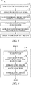
- FIG. 6 illustrates an example of a method 640 for determining a desired value for a device parameter.
- the method 640 can be an example of 540.
- the method starts at 641 by computing a signal metric reliability (XR) for each of the candidate signal metrics.
- the signal metric reliability can be computed using one or more of the signal metric sensitivity, the variability, or the covariability provided at 530. In an example, the signal metric reliability can be proportional to the signal metric sensitivity.
- one or more measurements ⁇ X ⁇ 1 can be generated in response to the stimulation when the device parameter is set to a first value (P 1 ); and one or more measurements ⁇ X ⁇ 2 can be generated in response to the stimulation when the device parameter is set to a second value (P 2 ).
- a representative value ⁇ 1 can be computed from the measurements ⁇ X ⁇ 1 and a representative value ⁇ 2 from the measurements ⁇ X ⁇ 2 .
- the representative value ⁇ 1 and ⁇ 2 can be computed as mean, median, weighted-mean, mode, or other central tendency of respective measurements.
- the signal metric reliability can be inversely proportional to the signal metric variability, such that a signal metric with a higher variability is less reliable for use in determining the desired value of the device parameter.
- the variability measure ( ⁇ ) can be computed using a plurality of measurements of the signal metric in response to the stimulation when the device parameter is set to a pre-determined value.
- the variability measure can be computed using the measurements ⁇ X ⁇ 1 , ⁇ X ⁇ 2 , or measurements during the baseline when no stimulation is delivered. Examples of the variability can include range, inter-quartile range, standard deviation, variance, sample variance, or other first-order, second-order, or higher-order statistics representing the degree of variation.
- the signal metric reliability can be proportional to the distance d 12 between ⁇ 1 and ⁇ 2 and inverse proportional to ⁇ .
- a signal metrics can be selected if the signal metric reliability meets a specified criterion. For example, a signal metric can be selected if the distance d 12 exceeds a reliability threshold, or if the SVR exceeds a reliability threshold.
- a metric-indicated device parameter value can be determined.
- the metric-indicated device parameter value can be determined using an extrapolation or interpolation of the relationship between the signal metric measurements and the corresponding device parameter values.
- an S1 intensity-AVD relationship can be constructed between the measurements of the S1 intensity in response to stimulation when the AVD is set to a number of values.
- the relationship can be represented by a regression model. Examples of the regression model can include linear regression, polynomial regression, power regression, logistic regression, and other parametric and non-parametric models.
- the S1 intensity-indicated AVD can then be determined using the extrapolation or interpolation using the regression model between the S1 intensity and the AVD values.
- the desired device parameter value can then be determined at 644 by combining the signal metric-indicated device parameter value of a subset or all of the selected signal metrics.
- the combination can include a linear combination of the metric-indicated device parameter values of the subset of the selected signal metrics. Each metric-indicated device parameter value can be weighted by the signal metric reliability associated with the respective selected signal metric.
- the combination can include a nonlinear combination of the metric-indicated device parameter value of the subset of the selected signal metrics, such as a decision tree, a neural network, a non-linear combination, or a multivariate regression model.
- the desired device parameter value can be used to generate stimulations at 550.
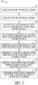
- FIG. 7 illustrates an example of a method 700 for determining a desired value for a device parameter.
- the IMD 110 including its various embodiments discussed in this document, is programmed to perform method 700, including its various embodiments discussed in this document.
- One or more physiologic signals are sensed at 710.
- the physiologic signals can be acquired by one or more physiologic sensors including, for example, pressure sensors, flow sensors, impedance sensors, accelerometers, microphone sensors, respiration sensors, temperature sensors, and blood chemical sensors.
- two or more signal metrics can be generated at 720.
- signal metrics can include features representing a statistical or a morphological characteristic of the physiologic signal. The features can be extracted in time-domain, frequency-domain, or joint time-frequency domain.
- P X a first signal metric vector X can be constructed.
- X can include measurements of the two or more signal metrics in response to stimulation when the device parameter is set to P X .
- P Y a second signal metric vector Y can be constructed.
- the signal metric Y can include measurements of the two or more signal metrics in response to the stimulation when the device parameter is set to the value Py.
- a target directional vector v can be generated using the signal metric vectors X and Y.
- the target directional vector can be generated using one or more of the sensitivity of the two or more signal metrics, the variability of the two or more signal metrics, or the covariability between the two or more signal metrics.
- the target directional vector can be computed using a joint sensitivity computed from the two or more signal metrics.
- the first value AVD X can be arbitrarily selected, so that AVD X can be less likely to be a desired AVD value; and the second value AVD Y can be chosen as a sub-optimal AVD value determined based on, for example, therapy history, prior AVD adjustment, or using external information.
- the target directional vector can be determined using the joint sensitivity computed from the two or more signal metrics and the covariability between two or more signal metrics.
- a representative M-dimensional vector ⁇ X can be computed using X MN
- a representative M-dimensional vector ⁇ Y can be computed using Y MN .
- a covariance matrix C can be generated using either X MN or Y MN or any combination of the repeated measurement of X and Y.
- the M-by-M covariance matrix C represents multivariate variability. In the M-dimensional signal metrics space, the M sensor readings at any given AVD can form an ellipse represented by covariance matrix C.
- the target directional vector can then be determined using one or more of ⁇ X , ⁇ Y , or C.
- the target directional vector v implicitly accounts for the sensitivity and the variability of the multiple signal metrics.
- a test signal metric vector can be constructed.
- the test signal metric vector can comprise measurements from the two or more signal metrics in response to the stimulation when the device parameter is set to a specified value.
- a plurality of candidate device parameter values can be stored in a memory, and the test signal metric vector can be constructed in response to the stimulation when the device parameter is set to one of the candidate device parameter values.
- a projection of the test signal metric vector onto the target directional vector v can be computed.
- the projection can be computed as a dot product between the test signal metric vector and the unit target directional vector v 0 .
- the projection can then be compared to a convergence criterion at 780.
- the candidate device parameter can be deemed the desired parameter value if the projection meets the convergence criterion. Otherwise, a different candidate device parameter value can be selected from the memory, and the resultant test signal metric vector can be projected to the unit target directional vector v 0 .
- the method 700 sweeps through the candidate device parameter values in the memory and determines the desired device parameter as the one that maximizes the projection onto the unit target directional vector v 0 .
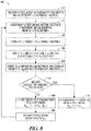
- FIG. 8 illustrates an example of a method 800 for adaptively determining a desired value for a device parameter.
- the IMD 110 including its various embodiments discussed in this document, can be programmed to perform method 800, including its various embodiments discussed in this document.
- the device parameter can be initialized to P 0 at 810 and the stimulation can be delivered to a target site in accordance with the initial value of the device parameter.
- the initial value of the device parameter can be chosen using empirical knowledge such as the historical performance of the stimulation therapy.
- a test signal metric vector X k (which corresponds to the device parameter value P k ) including measurements from M (M ⁇ 2) signal metrics can be constructed.
- a target directional vector v can be generated, such as by using the joint signal metric sensitivity alone or in conjunction with the covariability among the M signal metrics, as discussed in 740.
- the test signal metric vector X k can be projected onto the target directional vector v (or the unit target directional vector v 0 ) at 840.
- , can be computed at 850. The ⁇ can then be compared to a convergence threshold at 860.
- the device parameter can be adjusted from P k to the next value P k+1 .
- the increment or decrement of device parameter value P can be proportional to the comparison of ⁇ k and ⁇ k-1 .
- P k+1 can be decremented. If, however, ⁇ exceeds a convergence threshold and if ⁇ k ⁇ ⁇ k-1 , which suggests that the projection decreases as the device parameter changes from P k-1 to P k , then at 880, P k-1 can be incremented.
- exceeds a convergence threshold, then at the next iteration, AVD k+1 can be decremented, i.e., AVD k+1 AVD k - ⁇ • ⁇ k .
- the adjusted device parameter P k+1 can then be used in generating stimulation and deliver the stimulation to the target site at 890, and a new a test signal metric vector can be generated at 820.
- Method examples described herein can be machine or computer-implemented at least in part. Some examples can include a computer-readable medium or machine-readable medium encoded with instructions operable to configure an electronic device to perform methods as described in the above examples.
- An implementation of such methods can include code, such as microcode, assembly language code, a higher-level language code, or the like. Such code can include computer readable instructions for performing various methods. The code can form portions of computer program products. Further, in an example, the code can be tangibly stored on one or more volatile, non-transitory, or non-volatile tangible computer-readable media, such as during execution or at other times.
- Examples of these tangible computer-readable media can include, but are not limited to, hard disks, removable magnetic disks, removable optical disks (e.g., compact disks and digital video disks), magnetic cassettes, memory cards or sticks, random access memories (RAMs), read only memories (ROMs), and the like.
Claims (15)
- Dispositif médical ambulatoire, comprenant :un circuit de génération de stimulations (230) qui est configuré pour générer des stimulations pour stimuler un site cible ;un circuit d'analyseur de signal (210) qui est configuré pour recevoir un signal ou plusieurs signaux physiologique(s) et pour générer deux mesures de signal ou plus à partir des un ou plusieurs signaux physiologiques ;un circuit de réglage de paramètre de dispositif (220) qui est configuré pour déterminer une valeur de paramètre de dispositif souhaitée pour un paramètre de dispositif ;un circuit de contrôleur (240) qui est configuré de telle sorte qu'il soit inclus avec le circuit d'analyseur de signal (210), le circuit de réglage de paramètre de dispositif (220) et le circuit de génération de stimulation (230) ou de telle sorte qu'il soit couplé à ces mêmes circuits, le circuit de contrôleur (240) étant configuré pour programmer ou pour planifier la délivrance des stimulations en utilisant la valeur de paramètre de dispositif souhaitée ; caractérisé en ce que le circuit de réglage de paramètre de dispositif (210) comprend :un circuit de calculateur de sensibilité (221) qui est configuré pour déterminer, pour au moins deux des deux mesures de signal ou plus, une sensibilité respective vis-à-vis d'une perturbation qui est imprimée sur le paramètre de dispositif en réponse aux simulations, la sensibilité étant déterminée en utilisant une comparaison de valeurs de la même mesure de signal pendant des stimulations qui présentent des valeurs différentes du paramètre de dispositif ;un circuit de calculateur de variabilité (222) qui est configuré pour déterminer, pour au moins deux des deux mesures de signal ou plus, une variabilité respective en réponse aux stimulations ;un circuit de calculateur de co-variabilité (223) qui est configuré pour déterminer une co-variabilité entre au moins deux des deux mesures de signal ou plus en réponse aux stimulations ; etun circuit de fusion d'information (225) qui est configuré pour déterminer la valeur de paramètre de dispositif souhaitée en utilisant au moins un paramètre informationnel pris parmi la sensibilité pour les au moins deux mesures de signal, la variabilité pour les au moins deux mesures de signal et la co-variabilité entre les au moins deux mesures de signal.
- Dispositif médical selon la revendication 1, dans lequel :le circuit de génération de stimulations (230) est configuré pour générer un ou plusieurs train(s) de stimulations pour stimuler une ou plusieurs région(s) d'un cœur ; etle circuit de réglage de paramètre de dispositif (220) est configuré pour déterminer une valeur souhaitée pour une temporisation relative entre un premier événement au niveau d'un premier site du cœur et un second événement au niveau d'un second site du cœur.
- Dispositif médical selon l'une quelconque des revendications 1 ou 2, comprenant un ou plusieurs capteur(s) physiologique(s) qui est/sont configuré(s) de telle sorte qu'il(s) soit/soient inclus avec le circuit d'analyseur de signal (210) ou de telle sorte qu'il(s) soit/soient couplé(s) à ce même circuit, les un ou plusieurs capteurs physiologiques étant configurés pour détecter les un ou plusieurs signaux physiologiques, dans lequel le circuit d'analyseur de signal est configuré pour analyser les un ou plusieurs signaux physiologiques en provenance des un ou plusieurs capteurs physiologiques.
- Dispositif médical selon la revendication 3, dans lequel les un ou plusieurs capteurs physiologiques incluent un capteur physiologique qui est configuré pour détecter un signal de bruit du cœur, et le circuit d'analyseur de signal (210) est configuré pour utiliser le signal de bruit du cœur pour générer une ou plusieurs mesure(s) de bruits du cœur.
- Dispositif médical selon l'une quelconque des revendications 1 à 4, dans lequel le circuit de fusion d'information (225) comprend :un circuit d'estimateur de fiabilité de mesure de signal (310) qui est configuré pour calculer une fiabilité de mesure de signal pour au moins deux des deux mesures de signal ou plus en utilisant au moins un paramètre informationnel pris parmi la sensibilité, la variabilité et la co-variabilité ;un sélecteur de mesure de signal (320) qui est configuré pour sélectionner un sous-jeu à partir des deux mesures de signal ou plus en utilisant une comparaison entre les fiabilités de mesure de signal des deux mesures de signal ou plus ;un circuit de détermination de paramètre de dispositif indiqué par mesure (330) qui est configuré pour déterminer, pour une mesure de signal du sous-jeu sélectionné, une valeur de paramètre de dispositif indiquée par mesure ; etun circuit de fusion de paramètre de dispositif indiqué par mesure (340) qui est configuré pour déterminer la valeur de paramètre de dispositif souhaitée en utilisant une combinaison des valeurs de paramètre de dispositif indiquées par mesure avec les mesures de signal respectives du sous-jeu sélectionné.
- Système selon la revendication 5, dans lequel le circuit d'estimateur de fiabilité de mesure de signal (310) est configuré pour calculer la fiabilité de mesure de signal comme étant proportionnelle à la sensibilité de mesure de signal.
- Système selon la revendication 5, dans lequel le circuit d'estimateur de fiabilité de mesure de signal (310) est configuré pour calculer la fiabilité de mesure de signal comme étant inversement proportionnelle à la variabilité de mesure de signal.
- Dispositif médical selon la revendication 5, dans lequel :le circuit d'estimateur de fiabilité de mesure de signal (310) est configuré pour déterminer, pour au moins deux des deux mesures de signal ou plus, une première valeur de mesure de signal représentative (µ1) en réponse à une stimulation lorsque le paramètre de dispositif est défini à une première valeur et une seconde valeur de mesure de signal représentative (µ2) en réponse à une stimulation lorsque le paramètre de dispositif est défini à une seconde valeur ; etle sélecteur de mesure de signal (320) est configuré pour sélectionner la mesure de signal en réponse au fait qu'une mesure relative entre µ1 et µ2 satisfait un critère de fiabilité.
- Dispositif médical selon la revendication 8, dans lequel :le circuit d'estimateur de fiabilité de mesure de signal (310) est configuré pour calculer, pour au moins deux des deux mesures de signal ou plus, une variabilité de mesure de signal en utilisant une pluralité de mesures en réponse à une stimulation lorsque le paramètre de dispositif est défini à une valeur spécifiée et pour calculer un rapport sensibilité sur variabilité (SVR) en utilisant la mesure relative entre µ1 et µ2 et la variabilité de mesure de signal ; etle sélecteur de mesure de signal (320) est configuré pour sélectionner la mesure de signal en réponse au fait que le SVR satisfait un critère de fiabilité.
- Dispositif médical selon l'une quelconque des revendications 1 à 4, dans lequel le circuit de fusion d'information (225) comprend :un circuit de variation de mesure de signal cible (410) qui est configuré pour générer un vecteur directionnel cible qui représente la variation des deux mesures de signal ou plus en réponse à la stimulation lorsque le paramètre de dispositif est modifié d'une première valeur à une seconde valeur, le vecteur directionnel cible étant généré en utilisant au moins un paramètre informationnel pris parmi la sensibilité, la variabilité et la co-variabilité ;un circuit de mémoire (420) qui est configuré pour stocker une pluralité de valeurs pour le paramètre de dispositif ; etun circuit de calculateur de projection de signal (430) qui est couplé au circuit de mémoire et au circuit de variation de mesure de signal cible, le circuit de calculateur de projection de signal étant configuré pour :déterminer, pour une valeur stockée du paramètre de dispositif, un vecteur de mesure de signal qui comprend les valeurs des deux mesures de signal ou plus ; pourcalculer, pour une valeur stockée du paramètre de dispositif, une projection du vecteur de mesure de signal sur le vecteur directionnel cible ; et pourdéterminer la valeur de paramètre de dispositif souhaitée du paramètre de dispositif en réponse au fait que la projection satisfait un critère spécifié.
- Dispositif médical selon l'une quelconque des revendications 5 à 8, dans lequel le circuit d'estimateur de fiabilité de mesure de signal (310) est configuré pour calculer la fiabilité de mesure de signal comme étant proportionnelle à la sensibilité de mesure de signal et comme étant inversement proportionnelle à la variabilité de mesure de signal.
- Dispositif médical selon l'une quelconque des revendications 5 à 8, dans lequel le circuit de fusion de paramètre de dispositif indiqué par mesure (340) est configuré pour déterminer la valeur de paramètre de dispositif souhaitée en utilisant une combinaison linéaire des valeurs de paramètre de dispositif indiquées par mesure qui sont associées aux mesures de signal respectives du sous-jeu sélectionné, chaque valeur de paramètre de dispositif indiquée par mesure étant pondérée par la fiabilité de mesure de signal qui correspond à la mesure de signal sélectionnée.
- Dispositif médical selon la revendication 8, dans lequel le circuit d'estimateur de fiabilité de mesure de signal (310) est configuré pour calculer la fiabilité de mesure de signal en utilisant la distance entre une première valeur de mesure de signal représentative µ1 et une seconde valeur de mesure de signal représentative µ2.
- Dispositif médical selon l'une quelconque des revendications 1 à 13, dans lequel le circuit de calculateur de co-variabilité (223) est configuré pour déterminer la co-variabilité comme incluant une matrice de covariance entre au moins deux des deux mesures de signal ou plus en réponse aux stimulations.
- Dispositif médical selon la revendication 10, dans lequel le circuit de calculateur de projection de signal (430) est configuré pour régler de façon incrémentielle une valeur du paramètre de dispositif et pour déterminer la valeur de paramètre de dispositif souhaitée en réponse au fait que la projection du vecteur de mesure de signal qui correspond à la valeur de paramètre de dispositif réglée satisfait un critère de convergence spécifié.
Applications Claiming Priority (2)
| Application Number | Priority Date | Filing Date | Title |
|---|---|---|---|
| US201361776893P | 2013-03-12 | 2013-03-12 | |
| PCT/US2014/021287 WO2014158986A1 (fr) | 2013-03-12 | 2014-03-06 | Dispositif médical ayant une fusion à capteurs multiples |
Publications (2)
| Publication Number | Publication Date |
|---|---|
| EP2968916A1 EP2968916A1 (fr) | 2016-01-20 |
| EP2968916B1 true EP2968916B1 (fr) | 2021-05-19 |
Family
ID=50349955
Family Applications (1)
| Application Number | Title | Priority Date | Filing Date |
|---|---|---|---|
| EP14712509.0A Active EP2968916B1 (fr) | 2013-03-12 | 2014-03-06 | Dispositif médical ayant une fusion à capteurs multiples |
Country Status (5)
| Country | Link |
|---|---|
| US (2) | US9254390B2 (fr) |
| EP (1) | EP2968916B1 (fr) |
| JP (1) | JP6437997B2 (fr) |
| CN (1) | CN105120944B (fr) |
| WO (1) | WO2014158986A1 (fr) |
Families Citing this family (20)
| Publication number | Priority date | Publication date | Assignee | Title |
|---|---|---|---|---|
| WO2008070189A2 (fr) | 2006-12-06 | 2008-06-12 | The Cleveland Clinic Foundation | Procédé et système pour traiter une insuffisance cardiaque aiguë par neuromodulation |
| JP5692097B2 (ja) * | 2010-02-05 | 2015-04-01 | 日本電気株式会社 | 生体情報計測器、携帯端末装置、生体情報計測方法およびプログラム |
| EP2968916B1 (fr) | 2013-03-12 | 2021-05-19 | Cardiac Pacemakers, Inc. | Dispositif médical ayant une fusion à capteurs multiples |
| WO2015109239A1 (fr) | 2014-01-17 | 2015-07-23 | Medtronic, Inc. | Maîtrise des symptômes des troubles du comportement |
| SG10201808553QA (en) | 2014-05-22 | 2018-11-29 | Cardionomic Inc | Catheter and catheter system for electrical neuromodulation |
| AU2015315570B2 (en) | 2014-09-08 | 2020-05-14 | CARDIONOMIC, Inc. | Methods for electrical neuromodulation of the heart |
| CA2957791A1 (fr) | 2014-09-08 | 2016-03-17 | CARDIONOMIC, Inc. | Systemes catheter-electrode pour neuromodulation electrique |
| US10493278B2 (en) | 2015-01-05 | 2019-12-03 | CARDIONOMIC, Inc. | Cardiac modulation facilitation methods and systems |
| EP3389770B1 (fr) * | 2015-12-18 | 2020-08-26 | Sorin CRM SAS | Dispositif médical implantable actif de type resynchroniseur cardiaque avec adaptation dynamique du délai atrioventriculaire en fonction d'un degré de fusion détecté et quantifié |
| AU2017207457A1 (en) * | 2016-01-13 | 2018-08-09 | Joy Global Surface Mining Inc | Providing operator feedback during operation of an industrial machine |
| JP2019513032A (ja) | 2016-03-09 | 2019-05-23 | カーディオノミック,インク. | 心収縮神経刺激システムおよび方法 |
| CN109069060B (zh) | 2016-04-01 | 2021-04-27 | 心脏起搏器股份公司 | 用于检测恶化的心力衰竭的系统和方法 |
| JP6667017B2 (ja) * | 2016-06-01 | 2020-03-18 | カーディアック ペースメイカーズ, インコーポレイテッド | 複数部位刺激のためのシステム |
| US10960202B2 (en) | 2016-09-27 | 2021-03-30 | Medtronic, Inc. | Adaptive deep brain stimulation using movement desynchronization |
| EP3664703A4 (fr) | 2017-09-13 | 2021-05-12 | Cardionomic, Inc. | Systèmes de neurostimulation et procédés pour affecter la contractilité cardiaque |
| CN108577816B (zh) * | 2018-04-08 | 2020-04-28 | 西安交通大学 | 一种多传感器复合右心室电极及融合心脏起搏频率自适应调节方法 |
| CN112839602A (zh) | 2018-08-13 | 2021-05-25 | 卡迪诺米克公司 | 用于影响心脏收缩性和/或松弛性的系统和方法 |
| EP3856275B1 (fr) * | 2018-09-27 | 2023-01-18 | Heartware, Inc. | Estimation de la pam sur des patients équipés d'un dav |
| WO2020227234A1 (fr) | 2019-05-06 | 2020-11-12 | CARDIONOMIC, Inc. | Systèmes et procédés de débruitage de signaux physiologiques pendant une neuromodulation électrique |
| CN112336369B (zh) * | 2020-11-30 | 2021-09-10 | 山东大学 | 一种多通道心音信号的冠心病风险指数评估系统 |
Family Cites Families (15)
| Publication number | Priority date | Publication date | Assignee | Title |
|---|---|---|---|---|
| US7079896B1 (en) * | 2001-11-26 | 2006-07-18 | Pacesetter, Inc. | Methods of automatically optimizing AV delay by way of monitoring the heart sound |
| US20040220636A1 (en) | 2003-04-29 | 2004-11-04 | Medtronic, Inc. | Cardiac pacing therapy parameter programming |
| US7873413B2 (en) * | 2006-07-24 | 2011-01-18 | Cardiac Pacemakers, Inc. | Closed loop neural stimulation synchronized to cardiac cycles |
| US7672721B2 (en) | 2005-10-25 | 2010-03-02 | Medtronic, Inc. | System and method of AV interval selection in an implantable medical device |
| ATE536909T1 (de) | 2005-12-16 | 2011-12-15 | St Jude Medical | Implantierbares medizinprodukt mit therapiekontrolle |
| US8229557B2 (en) | 2007-03-29 | 2012-07-24 | Cardiac Pacemakers, Inc. | Estimating acute response to cardiac resynchronization therapy |
| US8041424B2 (en) | 2007-07-31 | 2011-10-18 | Medtronic, Inc. | Cardiac resynchronization therapy for patients with right bundle branch block |
| US8972007B2 (en) | 2007-09-25 | 2015-03-03 | Cardiac Pacemakers, Inc. | Variable shortening of AV delay for treatment of cardiac disease |
| US8777850B2 (en) * | 2008-10-31 | 2014-07-15 | Medtronic, Inc. | Heart failure patient management using an implantable monitoring system |
| US8209012B2 (en) | 2008-12-11 | 2012-06-26 | Pacesetter, Inc. | Mechanical indicators for individually adapting therapy in an implantable cardiac therapy device |
| US9101773B2 (en) * | 2009-02-06 | 2015-08-11 | Cardiac Pacemakers, Inc. | Cross-channel noise detector in implantable medical devices |
| WO2010123749A2 (fr) * | 2009-04-22 | 2010-10-28 | Cardiac Pacemakers, Inc. | Mesures de variabilité de la contractilité cardiaque durant l'ischémie |
| EP2263747B1 (fr) * | 2009-06-15 | 2015-08-26 | Sorin CRM SAS | Prothèse cardiaque implantable comprenant des moyens d'analyse de la tolérance du patient à un mode de stimulation privilégiant la conduction atrio-ventriculaire spontanée |
| US20110125208A1 (en) | 2009-11-20 | 2011-05-26 | Edward Karst | Methods and systems to monitor cardiac contractility |
| EP2968916B1 (fr) | 2013-03-12 | 2021-05-19 | Cardiac Pacemakers, Inc. | Dispositif médical ayant une fusion à capteurs multiples |
-
2014
- 2014-03-06 EP EP14712509.0A patent/EP2968916B1/fr active Active
- 2014-03-06 US US14/199,651 patent/US9254390B2/en active Active
- 2014-03-06 CN CN201480021017.3A patent/CN105120944B/zh not_active Expired - Fee Related
- 2014-03-06 WO PCT/US2014/021287 patent/WO2014158986A1/fr active Application Filing
- 2014-03-06 JP JP2016500747A patent/JP6437997B2/ja not_active Expired - Fee Related
-
2015
- 2015-12-15 US US14/969,638 patent/US9550066B2/en active Active
Also Published As
| Publication number | Publication date |
|---|---|
| EP2968916A1 (fr) | 2016-01-20 |
| US20160101290A1 (en) | 2016-04-14 |
| US9254390B2 (en) | 2016-02-09 |
| JP6437997B2 (ja) | 2018-12-12 |
| CN105120944A (zh) | 2015-12-02 |
| CN105120944B (zh) | 2017-05-31 |
| JP2016510682A (ja) | 2016-04-11 |
| WO2014158986A1 (fr) | 2014-10-02 |
| US20140277235A1 (en) | 2014-09-18 |
| US9550066B2 (en) | 2017-01-24 |
Similar Documents
| Publication | Publication Date | Title |
|---|---|---|
| EP2968916B1 (fr) | Dispositif médical ayant une fusion à capteurs multiples | |
| US10926095B2 (en) | Systems and methods for correcting cardiac conduction abnormality using his-bundle pacing | |
| US11173310B2 (en) | Multi-sensor based cardiac stimulation | |
| US20230122366A1 (en) | Systems and methods for heart failure management | |
| EP3638362B1 (fr) | Commande dynamique de thérapie d'insuffisance cardiaque | |
| US11051718B2 (en) | Systems and methods for managing heart failure using heart sounds | |
| US10195442B2 (en) | Methods and systems for multi-site pacing | |
| EP3325090B1 (fr) | Systèmes de sélection de site de stimulation | |
| US9227072B2 (en) | System and methods for improving device therapy using heart sounds |
Legal Events
| Date | Code | Title | Description |
|---|---|---|---|
| PUAI | Public reference made under article 153(3) epc to a published international application that has entered the european phase |
Free format text: ORIGINAL CODE: 0009012 |
|
| 17P | Request for examination filed |
Effective date: 20151009 |
|
| AK | Designated contracting states |
Kind code of ref document: A1 Designated state(s): AL AT BE BG CH CY CZ DE DK EE ES FI FR GB GR HR HU IE IS IT LI LT LU LV MC MK MT NL NO PL PT RO RS SE SI SK SM TR |
|
| AX | Request for extension of the european patent |
Extension state: BA ME |
|
| DAX | Request for extension of the european patent (deleted) | ||
| GRAP | Despatch of communication of intention to grant a patent |
Free format text: ORIGINAL CODE: EPIDOSNIGR1 |
|
| STAA | Information on the status of an ep patent application or granted ep patent |
Free format text: STATUS: GRANT OF PATENT IS INTENDED |
|
| INTG | Intention to grant announced |
Effective date: 20201201 |
|
| GRAS | Grant fee paid |
Free format text: ORIGINAL CODE: EPIDOSNIGR3 |
|
| GRAA | (expected) grant |
Free format text: ORIGINAL CODE: 0009210 |
|
| STAA | Information on the status of an ep patent application or granted ep patent |
Free format text: STATUS: THE PATENT HAS BEEN GRANTED |
|
| AK | Designated contracting states |
Kind code of ref document: B1 Designated state(s): AL AT BE BG CH CY CZ DE DK EE ES FI FR GB GR HR HU IE IS IT LI LT LU LV MC MK MT NL NO PL PT RO RS SE SI SK SM TR |
|
| REG | Reference to a national code |
Ref country code: GB Ref legal event code: FG4D |
|
| REG | Reference to a national code |
Ref country code: CH Ref legal event code: EP |
|
| REG | Reference to a national code |
Ref country code: DE Ref legal event code: R096 Ref document number: 602014077517 Country of ref document: DE |
|
| REG | Reference to a national code |
Ref country code: AT Ref legal event code: REF Ref document number: 1393405 Country of ref document: AT Kind code of ref document: T Effective date: 20210615 |
|
| REG | Reference to a national code |
Ref country code: IE Ref legal event code: FG4D |
|
| REG | Reference to a national code |
Ref country code: LT Ref legal event code: MG9D |
|
| REG | Reference to a national code |
Ref country code: AT Ref legal event code: MK05 Ref document number: 1393405 Country of ref document: AT Kind code of ref document: T Effective date: 20210519 |
|
| REG | Reference to a national code |
Ref country code: NL Ref legal event code: MP Effective date: 20210519 |
|
| PG25 | Lapsed in a contracting state [announced via postgrant information from national office to epo] |
Ref country code: FI Free format text: LAPSE BECAUSE OF FAILURE TO SUBMIT A TRANSLATION OF THE DESCRIPTION OR TO PAY THE FEE WITHIN THE PRESCRIBED TIME-LIMIT Effective date: 20210519 Ref country code: LT Free format text: LAPSE BECAUSE OF FAILURE TO SUBMIT A TRANSLATION OF THE DESCRIPTION OR TO PAY THE FEE WITHIN THE PRESCRIBED TIME-LIMIT Effective date: 20210519 Ref country code: BG Free format text: LAPSE BECAUSE OF FAILURE TO SUBMIT A TRANSLATION OF THE DESCRIPTION OR TO PAY THE FEE WITHIN THE PRESCRIBED TIME-LIMIT Effective date: 20210819 Ref country code: AT Free format text: LAPSE BECAUSE OF FAILURE TO SUBMIT A TRANSLATION OF THE DESCRIPTION OR TO PAY THE FEE WITHIN THE PRESCRIBED TIME-LIMIT Effective date: 20210519 Ref country code: HR Free format text: LAPSE BECAUSE OF FAILURE TO SUBMIT A TRANSLATION OF THE DESCRIPTION OR TO PAY THE FEE WITHIN THE PRESCRIBED TIME-LIMIT Effective date: 20210519 |
|
| PG25 | Lapsed in a contracting state [announced via postgrant information from national office to epo] |
Ref country code: IS Free format text: LAPSE BECAUSE OF FAILURE TO SUBMIT A TRANSLATION OF THE DESCRIPTION OR TO PAY THE FEE WITHIN THE PRESCRIBED TIME-LIMIT Effective date: 20210919 Ref country code: GR Free format text: LAPSE BECAUSE OF FAILURE TO SUBMIT A TRANSLATION OF THE DESCRIPTION OR TO PAY THE FEE WITHIN THE PRESCRIBED TIME-LIMIT Effective date: 20210820 Ref country code: LV Free format text: LAPSE BECAUSE OF FAILURE TO SUBMIT A TRANSLATION OF THE DESCRIPTION OR TO PAY THE FEE WITHIN THE PRESCRIBED TIME-LIMIT Effective date: 20210519 Ref country code: NO Free format text: LAPSE BECAUSE OF FAILURE TO SUBMIT A TRANSLATION OF THE DESCRIPTION OR TO PAY THE FEE WITHIN THE PRESCRIBED TIME-LIMIT Effective date: 20210819 Ref country code: PL Free format text: LAPSE BECAUSE OF FAILURE TO SUBMIT A TRANSLATION OF THE DESCRIPTION OR TO PAY THE FEE WITHIN THE PRESCRIBED TIME-LIMIT Effective date: 20210519 Ref country code: PT Free format text: LAPSE BECAUSE OF FAILURE TO SUBMIT A TRANSLATION OF THE DESCRIPTION OR TO PAY THE FEE WITHIN THE PRESCRIBED TIME-LIMIT Effective date: 20210920 Ref country code: ES Free format text: LAPSE BECAUSE OF FAILURE TO SUBMIT A TRANSLATION OF THE DESCRIPTION OR TO PAY THE FEE WITHIN THE PRESCRIBED TIME-LIMIT Effective date: 20210519 Ref country code: RS Free format text: LAPSE BECAUSE OF FAILURE TO SUBMIT A TRANSLATION OF THE DESCRIPTION OR TO PAY THE FEE WITHIN THE PRESCRIBED TIME-LIMIT Effective date: 20210519 Ref country code: SE Free format text: LAPSE BECAUSE OF FAILURE TO SUBMIT A TRANSLATION OF THE DESCRIPTION OR TO PAY THE FEE WITHIN THE PRESCRIBED TIME-LIMIT Effective date: 20210519 |
|
| PG25 | Lapsed in a contracting state [announced via postgrant information from national office to epo] |
Ref country code: NL Free format text: LAPSE BECAUSE OF FAILURE TO SUBMIT A TRANSLATION OF THE DESCRIPTION OR TO PAY THE FEE WITHIN THE PRESCRIBED TIME-LIMIT Effective date: 20210519 |
|
| PG25 | Lapsed in a contracting state [announced via postgrant information from national office to epo] |
Ref country code: DK Free format text: LAPSE BECAUSE OF FAILURE TO SUBMIT A TRANSLATION OF THE DESCRIPTION OR TO PAY THE FEE WITHIN THE PRESCRIBED TIME-LIMIT Effective date: 20210519 Ref country code: CZ Free format text: LAPSE BECAUSE OF FAILURE TO SUBMIT A TRANSLATION OF THE DESCRIPTION OR TO PAY THE FEE WITHIN THE PRESCRIBED TIME-LIMIT Effective date: 20210519 Ref country code: EE Free format text: LAPSE BECAUSE OF FAILURE TO SUBMIT A TRANSLATION OF THE DESCRIPTION OR TO PAY THE FEE WITHIN THE PRESCRIBED TIME-LIMIT Effective date: 20210519 Ref country code: SM Free format text: LAPSE BECAUSE OF FAILURE TO SUBMIT A TRANSLATION OF THE DESCRIPTION OR TO PAY THE FEE WITHIN THE PRESCRIBED TIME-LIMIT Effective date: 20210519 Ref country code: SK Free format text: LAPSE BECAUSE OF FAILURE TO SUBMIT A TRANSLATION OF THE DESCRIPTION OR TO PAY THE FEE WITHIN THE PRESCRIBED TIME-LIMIT Effective date: 20210519 Ref country code: RO Free format text: LAPSE BECAUSE OF FAILURE TO SUBMIT A TRANSLATION OF THE DESCRIPTION OR TO PAY THE FEE WITHIN THE PRESCRIBED TIME-LIMIT Effective date: 20210519 |
|
| REG | Reference to a national code |
Ref country code: DE Ref legal event code: R097 Ref document number: 602014077517 Country of ref document: DE |
|
| PLBE | No opposition filed within time limit |
Free format text: ORIGINAL CODE: 0009261 |
|
| STAA | Information on the status of an ep patent application or granted ep patent |
Free format text: STATUS: NO OPPOSITION FILED WITHIN TIME LIMIT |
|
| 26N | No opposition filed |
Effective date: 20220222 |
|
| PG25 | Lapsed in a contracting state [announced via postgrant information from national office to epo] |
Ref country code: IS Free format text: LAPSE BECAUSE OF FAILURE TO SUBMIT A TRANSLATION OF THE DESCRIPTION OR TO PAY THE FEE WITHIN THE PRESCRIBED TIME-LIMIT Effective date: 20210919 Ref country code: AL Free format text: LAPSE BECAUSE OF FAILURE TO SUBMIT A TRANSLATION OF THE DESCRIPTION OR TO PAY THE FEE WITHIN THE PRESCRIBED TIME-LIMIT Effective date: 20210519 |
|
| REG | Reference to a national code |
Ref country code: DE Ref legal event code: R119 Ref document number: 602014077517 Country of ref document: DE |
|
| PG25 | Lapsed in a contracting state [announced via postgrant information from national office to epo] |
Ref country code: MC Free format text: LAPSE BECAUSE OF FAILURE TO SUBMIT A TRANSLATION OF THE DESCRIPTION OR TO PAY THE FEE WITHIN THE PRESCRIBED TIME-LIMIT Effective date: 20210519 |
|
| REG | Reference to a national code |
Ref country code: CH Ref legal event code: PL |
|
| GBPC | Gb: european patent ceased through non-payment of renewal fee |
Effective date: 20220306 |
|
| REG | Reference to a national code |
Ref country code: BE Ref legal event code: MM Effective date: 20220331 |
|
| PG25 | Lapsed in a contracting state [announced via postgrant information from national office to epo] |
Ref country code: LU Free format text: LAPSE BECAUSE OF NON-PAYMENT OF DUE FEES Effective date: 20220306 Ref country code: LI Free format text: LAPSE BECAUSE OF NON-PAYMENT OF DUE FEES Effective date: 20220331 Ref country code: IE Free format text: LAPSE BECAUSE OF NON-PAYMENT OF DUE FEES Effective date: 20220306 Ref country code: GB Free format text: LAPSE BECAUSE OF NON-PAYMENT OF DUE FEES Effective date: 20220306 Ref country code: FR Free format text: LAPSE BECAUSE OF NON-PAYMENT OF DUE FEES Effective date: 20220331 Ref country code: DE Free format text: LAPSE BECAUSE OF NON-PAYMENT OF DUE FEES Effective date: 20221001 Ref country code: CH Free format text: LAPSE BECAUSE OF NON-PAYMENT OF DUE FEES Effective date: 20220331 |
|
| PG25 | Lapsed in a contracting state [announced via postgrant information from national office to epo] |
Ref country code: BE Free format text: LAPSE BECAUSE OF NON-PAYMENT OF DUE FEES Effective date: 20220331 |
|
| PG25 | Lapsed in a contracting state [announced via postgrant information from national office to epo] |
Ref country code: IT Free format text: LAPSE BECAUSE OF NON-PAYMENT OF DUE FEES Effective date: 20220306 |
|
| PG25 | Lapsed in a contracting state [announced via postgrant information from national office to epo] |
Ref country code: HU Free format text: LAPSE BECAUSE OF FAILURE TO SUBMIT A TRANSLATION OF THE DESCRIPTION OR TO PAY THE FEE WITHIN THE PRESCRIBED TIME-LIMIT; INVALID AB INITIO Effective date: 20140306 |