EP2967941B1 - Stent - Google Patents
Stent Download PDFInfo
- Publication number
- EP2967941B1 EP2967941B1 EP14708185.5A EP14708185A EP2967941B1 EP 2967941 B1 EP2967941 B1 EP 2967941B1 EP 14708185 A EP14708185 A EP 14708185A EP 2967941 B1 EP2967941 B1 EP 2967941B1
- Authority
- EP
- European Patent Office
- Prior art keywords
- stent
- radius
- curvature
- inches
- segment
- Prior art date
- Legal status (The legal status is an assumption and is not a legal conclusion. Google has not performed a legal analysis and makes no representation as to the accuracy of the status listed.)
- Active
Links
Images


Classifications
-
- A—HUMAN NECESSITIES
- A61—MEDICAL OR VETERINARY SCIENCE; HYGIENE
- A61F—FILTERS IMPLANTABLE INTO BLOOD VESSELS; PROSTHESES; DEVICES PROVIDING PATENCY TO, OR PREVENTING COLLAPSING OF, TUBULAR STRUCTURES OF THE BODY, e.g. STENTS; ORTHOPAEDIC, NURSING OR CONTRACEPTIVE DEVICES; FOMENTATION; TREATMENT OR PROTECTION OF EYES OR EARS; BANDAGES, DRESSINGS OR ABSORBENT PADS; FIRST-AID KITS
- A61F2/00—Filters implantable into blood vessels; Prostheses, i.e. artificial substitutes or replacements for parts of the body; Appliances for connecting them with the body; Devices providing patency to, or preventing collapsing of, tubular structures of the body, e.g. stents
- A61F2/82—Devices providing patency to, or preventing collapsing of, tubular structures of the body, e.g. stents
- A61F2/86—Stents in a form characterised by the wire-like elements; Stents in the form characterised by a net-like or mesh-like structure
- A61F2/90—Stents in a form characterised by the wire-like elements; Stents in the form characterised by a net-like or mesh-like structure characterised by a net-like or mesh-like structure
- A61F2/91—Stents in a form characterised by the wire-like elements; Stents in the form characterised by a net-like or mesh-like structure characterised by a net-like or mesh-like structure made from perforated sheets or tubes, e.g. perforated by laser cuts or etched holes
- A61F2/915—Stents in a form characterised by the wire-like elements; Stents in the form characterised by a net-like or mesh-like structure characterised by a net-like or mesh-like structure made from perforated sheets or tubes, e.g. perforated by laser cuts or etched holes with bands having a meander structure, adjacent bands being connected to each other
-
- A—HUMAN NECESSITIES
- A61—MEDICAL OR VETERINARY SCIENCE; HYGIENE
- A61F—FILTERS IMPLANTABLE INTO BLOOD VESSELS; PROSTHESES; DEVICES PROVIDING PATENCY TO, OR PREVENTING COLLAPSING OF, TUBULAR STRUCTURES OF THE BODY, e.g. STENTS; ORTHOPAEDIC, NURSING OR CONTRACEPTIVE DEVICES; FOMENTATION; TREATMENT OR PROTECTION OF EYES OR EARS; BANDAGES, DRESSINGS OR ABSORBENT PADS; FIRST-AID KITS
- A61F2/00—Filters implantable into blood vessels; Prostheses, i.e. artificial substitutes or replacements for parts of the body; Appliances for connecting them with the body; Devices providing patency to, or preventing collapsing of, tubular structures of the body, e.g. stents
- A61F2/82—Devices providing patency to, or preventing collapsing of, tubular structures of the body, e.g. stents
- A61F2/844—Devices providing patency to, or preventing collapsing of, tubular structures of the body, e.g. stents folded prior to deployment
-
- A—HUMAN NECESSITIES
- A61—MEDICAL OR VETERINARY SCIENCE; HYGIENE
- A61F—FILTERS IMPLANTABLE INTO BLOOD VESSELS; PROSTHESES; DEVICES PROVIDING PATENCY TO, OR PREVENTING COLLAPSING OF, TUBULAR STRUCTURES OF THE BODY, e.g. STENTS; ORTHOPAEDIC, NURSING OR CONTRACEPTIVE DEVICES; FOMENTATION; TREATMENT OR PROTECTION OF EYES OR EARS; BANDAGES, DRESSINGS OR ABSORBENT PADS; FIRST-AID KITS
- A61F2/00—Filters implantable into blood vessels; Prostheses, i.e. artificial substitutes or replacements for parts of the body; Appliances for connecting them with the body; Devices providing patency to, or preventing collapsing of, tubular structures of the body, e.g. stents
- A61F2/82—Devices providing patency to, or preventing collapsing of, tubular structures of the body, e.g. stents
- A61F2/86—Stents in a form characterised by the wire-like elements; Stents in the form characterised by a net-like or mesh-like structure
-
- A—HUMAN NECESSITIES
- A61—MEDICAL OR VETERINARY SCIENCE; HYGIENE
- A61F—FILTERS IMPLANTABLE INTO BLOOD VESSELS; PROSTHESES; DEVICES PROVIDING PATENCY TO, OR PREVENTING COLLAPSING OF, TUBULAR STRUCTURES OF THE BODY, e.g. STENTS; ORTHOPAEDIC, NURSING OR CONTRACEPTIVE DEVICES; FOMENTATION; TREATMENT OR PROTECTION OF EYES OR EARS; BANDAGES, DRESSINGS OR ABSORBENT PADS; FIRST-AID KITS
- A61F2/00—Filters implantable into blood vessels; Prostheses, i.e. artificial substitutes or replacements for parts of the body; Appliances for connecting them with the body; Devices providing patency to, or preventing collapsing of, tubular structures of the body, e.g. stents
- A61F2/95—Instruments specially adapted for placement or removal of stents or stent-grafts
-
- A—HUMAN NECESSITIES
- A61—MEDICAL OR VETERINARY SCIENCE; HYGIENE
- A61F—FILTERS IMPLANTABLE INTO BLOOD VESSELS; PROSTHESES; DEVICES PROVIDING PATENCY TO, OR PREVENTING COLLAPSING OF, TUBULAR STRUCTURES OF THE BODY, e.g. STENTS; ORTHOPAEDIC, NURSING OR CONTRACEPTIVE DEVICES; FOMENTATION; TREATMENT OR PROTECTION OF EYES OR EARS; BANDAGES, DRESSINGS OR ABSORBENT PADS; FIRST-AID KITS
- A61F2/00—Filters implantable into blood vessels; Prostheses, i.e. artificial substitutes or replacements for parts of the body; Appliances for connecting them with the body; Devices providing patency to, or preventing collapsing of, tubular structures of the body, e.g. stents
- A61F2/82—Devices providing patency to, or preventing collapsing of, tubular structures of the body, e.g. stents
- A61F2/86—Stents in a form characterised by the wire-like elements; Stents in the form characterised by a net-like or mesh-like structure
- A61F2/90—Stents in a form characterised by the wire-like elements; Stents in the form characterised by a net-like or mesh-like structure characterised by a net-like or mesh-like structure
- A61F2/91—Stents in a form characterised by the wire-like elements; Stents in the form characterised by a net-like or mesh-like structure characterised by a net-like or mesh-like structure made from perforated sheets or tubes, e.g. perforated by laser cuts or etched holes
- A61F2/915—Stents in a form characterised by the wire-like elements; Stents in the form characterised by a net-like or mesh-like structure characterised by a net-like or mesh-like structure made from perforated sheets or tubes, e.g. perforated by laser cuts or etched holes with bands having a meander structure, adjacent bands being connected to each other
- A61F2002/91508—Stents in a form characterised by the wire-like elements; Stents in the form characterised by a net-like or mesh-like structure characterised by a net-like or mesh-like structure made from perforated sheets or tubes, e.g. perforated by laser cuts or etched holes with bands having a meander structure, adjacent bands being connected to each other the meander having a difference in amplitude along the band
-
- A—HUMAN NECESSITIES
- A61—MEDICAL OR VETERINARY SCIENCE; HYGIENE
- A61F—FILTERS IMPLANTABLE INTO BLOOD VESSELS; PROSTHESES; DEVICES PROVIDING PATENCY TO, OR PREVENTING COLLAPSING OF, TUBULAR STRUCTURES OF THE BODY, e.g. STENTS; ORTHOPAEDIC, NURSING OR CONTRACEPTIVE DEVICES; FOMENTATION; TREATMENT OR PROTECTION OF EYES OR EARS; BANDAGES, DRESSINGS OR ABSORBENT PADS; FIRST-AID KITS
- A61F2/00—Filters implantable into blood vessels; Prostheses, i.e. artificial substitutes or replacements for parts of the body; Appliances for connecting them with the body; Devices providing patency to, or preventing collapsing of, tubular structures of the body, e.g. stents
- A61F2/82—Devices providing patency to, or preventing collapsing of, tubular structures of the body, e.g. stents
- A61F2/86—Stents in a form characterised by the wire-like elements; Stents in the form characterised by a net-like or mesh-like structure
- A61F2/90—Stents in a form characterised by the wire-like elements; Stents in the form characterised by a net-like or mesh-like structure characterised by a net-like or mesh-like structure
- A61F2/91—Stents in a form characterised by the wire-like elements; Stents in the form characterised by a net-like or mesh-like structure characterised by a net-like or mesh-like structure made from perforated sheets or tubes, e.g. perforated by laser cuts or etched holes
- A61F2/915—Stents in a form characterised by the wire-like elements; Stents in the form characterised by a net-like or mesh-like structure characterised by a net-like or mesh-like structure made from perforated sheets or tubes, e.g. perforated by laser cuts or etched holes with bands having a meander structure, adjacent bands being connected to each other
- A61F2002/91516—Stents in a form characterised by the wire-like elements; Stents in the form characterised by a net-like or mesh-like structure characterised by a net-like or mesh-like structure made from perforated sheets or tubes, e.g. perforated by laser cuts or etched holes with bands having a meander structure, adjacent bands being connected to each other the meander having a change in frequency along the band
-
- A—HUMAN NECESSITIES
- A61—MEDICAL OR VETERINARY SCIENCE; HYGIENE
- A61F—FILTERS IMPLANTABLE INTO BLOOD VESSELS; PROSTHESES; DEVICES PROVIDING PATENCY TO, OR PREVENTING COLLAPSING OF, TUBULAR STRUCTURES OF THE BODY, e.g. STENTS; ORTHOPAEDIC, NURSING OR CONTRACEPTIVE DEVICES; FOMENTATION; TREATMENT OR PROTECTION OF EYES OR EARS; BANDAGES, DRESSINGS OR ABSORBENT PADS; FIRST-AID KITS
- A61F2/00—Filters implantable into blood vessels; Prostheses, i.e. artificial substitutes or replacements for parts of the body; Appliances for connecting them with the body; Devices providing patency to, or preventing collapsing of, tubular structures of the body, e.g. stents
- A61F2/82—Devices providing patency to, or preventing collapsing of, tubular structures of the body, e.g. stents
- A61F2/86—Stents in a form characterised by the wire-like elements; Stents in the form characterised by a net-like or mesh-like structure
- A61F2/90—Stents in a form characterised by the wire-like elements; Stents in the form characterised by a net-like or mesh-like structure characterised by a net-like or mesh-like structure
- A61F2/91—Stents in a form characterised by the wire-like elements; Stents in the form characterised by a net-like or mesh-like structure characterised by a net-like or mesh-like structure made from perforated sheets or tubes, e.g. perforated by laser cuts or etched holes
- A61F2/915—Stents in a form characterised by the wire-like elements; Stents in the form characterised by a net-like or mesh-like structure characterised by a net-like or mesh-like structure made from perforated sheets or tubes, e.g. perforated by laser cuts or etched holes with bands having a meander structure, adjacent bands being connected to each other
- A61F2002/9155—Adjacent bands being connected to each other
- A61F2002/91575—Adjacent bands being connected to each other connected peak to trough
Definitions
- the present disclosure relates generally to stents, and, in particular, relates to stents having nodes with particular radii of curvatures.
- Stents are widely used for numerous applications where the stent is placed in the lumen of a patient and expanded. Such stents may be used in coronary or other vasculature, as well as other body lumens.
- stents are cylindrical members. The stents expand from reduced diameters to enlarged diameters. Stents may either be self-expanding or balloon-expandable. Self-expanding stents are generally inserted into vasculature via a delivery device; the removal of the delivery device causes the stent to radially expand. Balloon-expandable stents are placed on a balloon catheter with the stent in the reduced-diameter state. So placed, the stent is advanced on the catheter to a placement site. At the site, the balloon is inflated to expand the stent to the enlarged diameter. The balloon is deflated and removed, leaving the enlarged diameter stent in place. So used, such stents are used to substantially retain or expand diameters of occluded sites within a patient's vasculature or other lumen.
- stents are numerous.
- U.S. Pat. No. 5,449,373 to Pinchasik et al. teaches a stent with at least two rigid segments joined by a flexible connector.
- U.S. Pat. No. 5,695,516 to Fischell teaches a stent with a cell having a butterfly shape when the stent is in a reduced-diameter state. Upon expansion of the stent, the cell assumes a hexagonal shape.
- EP 1523959 describes a stent with multiple segments.
- US patent application no. 2002/007212 describes an expandable stent.
- the stent When stents are placed in certain parts of the body, it may be desirable for the stent to be both strong and flexible. For example, when a stent is placed within a patient's vasculature at or near a patient's joint (e.g., hip, knee, elbow, etc.), the stent may be bent often and may be subject to a relatively large amount of mechanical strain. Thus, a stent that is both flexible and strong may be desirable for use in these and other instances.
- a stent that is both flexible and strong may be desirable for use in these and other instances.
- a stent comprising a stent body and a plurality of cells.
- Each cell includes two structural members extending in an undulating pattern.
- Each structural member includes a plurality of cell segments defining a plurality of nodes therebetween. The radius of curvature of a first node is different from the radius of curvature of a second node.
- the radius of curvature of the first node is between about 200% and about 700% larger than the radius of curvature of the second node.
- the radius of curvature of the first node is between about 500% and about 600% larger than the radius of curvature of the second node.
- the radius of curvature of the first node is about 250% larger than the radius of curvature of the second node.
- the radius of curvature of the first node is between about 0.0076 centimetres (cm) (0.0030 inches) and about 0.0102 cm (0.0040 inches).
- the radius of curvature of the second node is between about 0.0003 cm (0.0001 inches) and about 0.0025 cm (0.0010 inches).
- the stent body includes a predeployed inside diameter of between about 0.127 cm (0.0500 inches) and about 0.1524 cm (0.0600 inches).
- the present invention relates to a stent comprising a stent body defining a length and comprising a plurality of cells.
- Each cell comprises two structural members extending in an undulating pattern.
- Each structural member comprises a plurality of cell segments defining a plurality of peaks of valleys therebetween.
- a first segment and a second segment define a first peak.
- the second segment and a third segment define a first valley.
- the third segment and a fourth segment define a second peak.
- the fourth segment and a fifth segment define a second valley.
- the fifth segment and a sixth segment define a third peak.
- the first peak and the first valley include a first radius of curvature
- the second peak, the third peak and the second valley include a second radius of curvature.
- the first radius of curvature is larger than the second radius of curvature.
- the first radius of curvature is between about 200% and about 700% larger than the second radius of curvature.
- the first radius of curvature is between about 500% and about 600% larger than the second radius of curvature.
- the first radius of curvature is about 250% larger than the second radius of curvature.
- the first radius of curvature is between about 0.0076 cm (0.0030 inches) and about 0.0102 cm (0.0040 inches).
- the second curvature is between about 0.0003 cm (0.0001 inches) and about 0.0025 cm (0.0010 inches).
- each structural member includes a seventh segment and an eighth segment.
- the sixth segment and the seventh segment define a third valley.
- the seventh segment and the eighth segment define a fourth peak.
- the third valley includes the second radius of curvature
- the fourth peak includes the first radius of curvature.
- the first radius of curvature is between about 200% and about 700% larger than the second radius of curvature.
- the first radius of curvature is between about 0.0076 cm (0.0030 inches) and about 0.0102 cm (0.0040 inches), and the second radius of curvature is between about 0.0003 cm (0.0001 inches) and about 0.0025 cm (0.0010 inches).
- the stent body includes a predeployed inside diameter of between about 0.127 cm (0.0500 inches) and about 0.1524 cm (0.0600 inches).
- proximal and distal refer to a direction or a position along a longitudinal axis of a catheter or medical instrument.
- the "proximal” or “trailing” end of the instrument is generally the segment of the instrument that is closest to the clinician or to the entrance site into a body.
- the “distal” or “leading” end of the instrument is generally the segment of the instrument placed farthest into a body lumen from the entrance site.
- preloaded relates to the configuration of the stent prior to the stent being loaded into a catheter
- predeployed relates to the configuration of the stent while the stent is compacted into the catheter.
- the stent of the present disclosure has particular application in the vasculature of a patient where it is subject to a relatively high amount of strain and movement.
- the disclosed stent may be suitable for use within the vasculature of a patient's hip area, e.g., to help reduce problems associated with a deep vein thrombosis (DVT).
- the disclosed stent may be used in any interventional, diagnostic, and/or therapeutic procedure.
- the stent may be a component of an apparatus or system used in conjunction with any of the above applications.
- the present disclosure includes a stent 100.
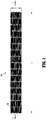
- Stent 100 may be expanded from a rest diameter (and corresponding a rest circumference) to an expanded or enlarged diameter. While stent 100 is generally used when in a cylindrical configuration, for ease of illustration FIG. 1 illustrates a stent 100 in a flattened condition. Moreover, FIG. 1 shows stent 100 cut longitudinally along its length L and laid flat, and is representative of the stent 100 after stent 100 has been laser cut from a shape-memory tube, for instance, but before stent 100 has been shape-set to the expanded diameter. FIG. 4 shows a portion of the stent 100 after the stent has been shape-set to the desired expanded diameter. In both FIGS.
- the stent 100 extends along elongated axis A--A and includes a stent body (i.e., a three-dimensional structure) having cell defining portions that define a plurality of cells 120, which are bounded areas which are open (i.e., extend through the wall thickness of the stent 100).
- a stent body i.e., a three-dimensional structure
- the cells 120 are generally more open than the cells depicted in FIG. 1 .
- cells 120 have a longitudinal or major axis X M --X M and a transverse or minor axis X m -- X m ; the major axis of the cell X M --X M is perpendicular to the longitudinal axis A--A of stent 100.
- cell 120 may be repeated throughout a least a portion of the length L and the diameter D of the stent 100 (i.e., each cell 120 may be substantially identical to other cells 120).
- first connection locations 130 and second connection locations 132 are where circumferentially adjacent cell defining structures, as defined relative to axis A--A, are connected together, and where longitudinally adjacent cell defining portions, as defined relative to the axis A--A, are connected together.
- cells 120 are defined by portions of the tube material and include first and second longitudinal segments 140a and 140b, collectively referred to as cell segments 140.
- each cell segment 140 has an undulating pattern which defines a plurality of peaks 150, 152, 154, 156 and valleys 160, 162, 164.
- the peaks 150, 152, 154, 156 are spaced outwardly or away from the longitudinal axis X M --X M
- the valleys 160, 162, 164 are spaced inwardly or toward the longitudinal axis X M --X M .
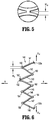
- FIGS. 3 and 6 are enlarged portions of a stent illustrating certain aspects of a stent design that can be optimized based on the desired performance of the stent.
- Each cell segment 140 is shown including: 1) a first segment 141 that extends from a first connection location 130a to peak 150; 2) a second segment 142 that extends from peak 150 to valley 160; 3) a third segment 143 that extends from valley 160 to peak 152; 4) a fourth segment 144 that extends from peak 152 to valley 162; 5) a fifth segment 145 that extends from valley 162 to peak 154; 6) a sixth segment 146 that extends from peak 154 to valley 164; 7) a seventh segment 147 that extends from valley 164 to peak 156; and 8) an eighth segment 148 that extends from peak 156 to a second connection location 130b.
- peak 152 is part of connection location 132. Collectively, peaks and valleys are referred to herein as nodes.
- segments 141-148 extend generally longitudinally along stent 100.
- the term "generally longitudinally” will be understood to mean that segments 141-148 are closer to a parallel relationship relative to the axis A--A of stent 100 (e.g., FIG. 3 ) than to a transverse relationship relative to the axis A--A of stent 100.
- Each node comprises a generally semi-circular arcuate segment including a radius of curvature "Rs", a length “Ls” (along axis A-A), and a width “Ws” (perpendicular to axis A-A) (see FIG. 3 ).
- the radius of curvature "Rs” is defined as the distance of the circular arc which best approximates the curve at that point, and is measured along an inside edge of the node, as shown in FIG. 3 .
- peak 150 and valley 160 may comprise a radius of curvature between about 0.0076 cm (0.00300 inches) and about 0.0102 cm (0.00400 inches) (e.g., equal to about 0.0808 cm (0.00318 inches)).
- the valley 162, peak 152, peak 154, valley 164, and peak 156 may comprise a radius of curvature between about 0.0003 cm (0.0001 inches) and about 0.0025 cm (0.0010 inches) (e.g., equal to about 0.0013 cm (0.0005 inches)).
- the radii of curvature of peak 150 and valley 160 are equal or substantially equal to each other, and it is envisioned that the radii of curvature of each of valley 162, peak 152, peak 154, valley 164, and peak 156 are equal or substantially equal to each other. It is further disclosed that any peak and any valley of each cell 120 can have any of the disclosed radii of curvature.
- a stent may have more than two distinct radii of curvature within each cell 120.
- stent 100 includes cells 120 where a larger (or largest) radius of curvature between adjacent nodes is between about 200% and about 700% (e.g., approximately 250%) larger than the smaller (or smallest) radius of curvature between adjacent nodes.
- the width of peak 150 and valley 160 may be between about 0.0635 cm (0.0250 inches) and about 0.0673 cm (0.0265 inches) (e.g., equal to about 0.0655 cm (0.0258 inches)).
- the width of valley 162, peak 152, peak 154, valley 164 and peak 156 may be between about 0.0600 cm (0.0240 inches) and about 0.0635 cm (0.0250 inches) (e.g., equal to about 0.0622 cm (0.0245 inches)). It is further envisioned that any peak and any valley of each cell 120 can have any of the disclosed widths.
- the length of peak 150 and valley 160 may be between about 0.0381 cm (0.0150 inches) and about 0.0432 cm (0.0170 inches) (e.g., equal to about 0.0406 cm (0.0160 inches)).
- the length of valley 162, peak 152, peak 154, valley 164 and peak 156 may be between about 0.0381 cm (0.0150 inches) and about 0.0432 cm (0.0170 inches) (e.g., equal to about 0.0406 cm (0.0160 inches)). It is further envisioned that any peak and any valley of each cell 120 may have any of the described lengths.
- the width "W CP " of connecting portions 130 and 132 may be between about 0.0254 cm (0.0100 inches) and about 0.0508 cm (0.0200 inches) (e.g., equal to about 0.0378 cm (0.0149 inches)).
- the stent 100 includes cells 120 having multiple nodes, wherein at least one node has a different radius from the other nodes. It is envisioned that these features help extend the life and/or durability of the disclosed stent 100.
- the mechanical strains undergone by stent 100 when stent 100 is within a patient's vasculature results in a more balanced distribution of strains versus a typical stent where each node has the same radius, for example.
- a combination of finite element analysis, durability testing, fatigue testing, and repeating bending load testing may be performed to help determine the ranges of dimensions for each node and to tune the desired performance of a given stent 100.
- the radius of the node that experiences the highest strains during testing (e.g., finite element analysis, durability testing, fatigue testing, and/or repeating bending load testing) is increased. If/when a different node experiences the highest strains during a subsequent test, the radius of that node is increased. This testing process is repeated until the strength and/or size of the compacted diameter become unacceptable for its desired application, and/or until additional increases in node radius provides negligible additional improvement in strength or durability.
- stent 100 When stent 100 is compacted into the catheter (i.e., its predeployed configuration), the diameter of stent 100 is reduced as compared to when stent 100 has not yet been loaded into the catheter (i.e., its preloaded configuration). This associated reduction in stent circumference is accommodated by reduction in the angles between segments which results in an increase in bending strain (e.g., especially adjacent nodes). As the cell is deformed (e.g., when stent 100 is loaded into catheter, or when the delivery system is navigating through the vasculature to the treatment site), especially during bending or axial loading, certain angles between adjacent segments increase or decrease more than others due to the lack of symmetry inherent in most flexible stent designs. As a result, there is a greater amount of strain in the nodes that connect those adjacent segments. The amount of strain concentrated near the nodes can be calculated using finite element analysis, for example.
- the maximum strain in a deformed stent is called the peak strain.
- the peak strain typically occurs in a single segment in the vicinity of a node although it may occur elsewhere in the stent depending on the stent design.
- Predominant strains in stents may be tensile (usually defined as positive) or compressive (usually defined as negative). Strains can be categorized as being of two kinds: normal strains and shear strains. Normal strains can be positive (e.g., tensile) or negative (e.g., compressive). There are positive and negative shear strains as well, but in this case the sign convention is arbitrary, and physically there is no real difference between positive and negative shear strains. Normal strains, which are also referred to as principal strains, are generally the basis for strain analysis and durability analysis of stents.
- High tensile strains may cause cracks to initiate and propagate through the stent, leading to reduced fatigue life and stent fracture (i.e., failure mode). Compressive strains do not tend to cause cracks, and so generally do not cause reduced stent life unless the magnitude of the strain is extraordinary. Some portions of a deformed stent may be highly strained during use while other portions may not be strained at all. A deformed stent can be thought of as a collection of tiny volumetric regions, each region having a strain level; collectively, the strain levels of the regions range from a maximum negative value to a maximum positive value.
- stents are designed such that the strain in the stent remains at a low level under pulsatile loading conditions, i.e. under oscillating circumferential compressive strains.
- stents implanted in other locations for example within a patient's vasculature at or near a patient's joint, can subject a stent to larger amounts of strain than previously predicted.
- Bending and any associated elongation of stent 100 results in concentration of tensile strains at and within particular nodes thereby exposing the segments near or adjacent the nodes, and the nodes themselves, to lower fatigue life. Concentration of compressive strains in other nodes permit the segments near or adjacent those nodes to sustain higher fatigue life. As such, balancing the strains experienced by the stent 100 increases the overall fatigue life of stent 100. Balancing the strain may involve changing the design of the stent 100 such that the nodes that are otherwise exposed to higher levels of tensile strains have a way to distribute that strain to help improve the fatigue life of the particular node and adjacent segments, and thus, help improve the fatigue life of the entire stent 100.
- the stent 100 of the present disclosure helps balance the strain by providing nodes with different radii of curvature from one another. As the strain is concentrated in regions where the radius of curvature is the smallest, it follows that by increasing the radius, the peak strain is reduced. The nodes of each cell that undergo the larger amount of strain have a larger radius associated therewith. Thus, nodes having the larger radius of curvature have a lower amount of peak strain associated therewith, and which thus improves fatigue life (i.e., helps prevent the stent from breaking). Further, the particular nodes of stent 100 that include a larger radius of curvature are the nodes that were found to undergo the highest peak strains during various testing procedures. Therefore, the overall life and performance of the stent is improved.
- stent 100 is compacted to a relatively small diameter in order to enable stent 100 to fit into a delivery system that travels through a patient's vasculature.
- the minimum compaction diameter increases in proportion to the increase in radius. If the required compaction diameter is desired to be a fixed amount, then as the node radius is increased, the segment widths would have to decrease. This decrease in segment width may lead to a decrease in stent strength.
- the diameter of the delivery system may be less critical for two reasons: 1) veins generally have larger diameters than arteries; and 2) blood pressure is lower in veins versus arteries, so the size of an access hole made to get the delivery device into a vein may be less critical, as once the procedure is complete, it is easier to stop the bleeding from a hole in a vein than in an artery.
- the design of a stent can be tuned for a venous application by considering the desired strength of the stent, the desired durability, and the desired size of its compacted diameter, along with the interplay between these criteria.
- At least one node of stent 100 includes a non-constant radius of curvature.
- a stent having a combination of nodes with different radii of curvature and with non-constant radii of curvature may further augment the balanced distribution of forces.
- each cell 120 and the entire stent 100 can be of any reasonable dimension for the intended purpose of use within a patient's vasculature. Likewise, the total number of cells 120 can be of any reasonable value. Further, as shown in Figure 4 , connector members 180 may be included on stent 100 to temporarily secure stent 100 to a delivery device, for example.
- the inside diameter of a preloaded stent 100 (i.e., prior to insertion into a catheter) is between about 1.27 cm (0.5000 inches) and about 1.524 cm (0.6000 inches), and the inside diameter of a predeployed stent 100 (i.e., compacted within a catheter) is between about 0.127 cm (0.0500 inches) and about 0.1524 cm (0.0600 inches).
- stent 100 is advanced to a site in a bodily lumen. Stent 100 is then expanded at the site. Stent 100 may be expanded through any conventional means.
- stent 100 may be placed on the balloon tip of a catheter.
- the balloon is expanded at the site to generate radial forces on the interior of stent 100.
- the radial forces urge stent 100 to radially expand, e.g., without appreciable longitudinal expansion or contraction.
- Plastic deformation of the material of stent 100 e.g., stainless steel
- the stent 100 may be formed of a super-elastic or shape memory material (e.g., nitinol).
- stent 100 may be lined with either an inner or outer sleeve (such as polyester fabric or ePTFE) to facilitate tissue growth. Also, at least a portion of stent 100 may be coated with radiopaque coatings such as platinum, gold, tungsten or tantalum. In addition to materials previously discussed, stent 100 may be formed of other materials, including, without limitation, MP35N, tantalum, platinum, gold, Elgiloy and Phynox.
- stent 100 When forming stent 100 from shape memory metal such as nitinol, stent 100 can be laser cut from a nitinol tube. Thereafter, stent 100 can be subjected to a shape-setting process in which the cut tube is expanded on a mandrel and then heated. Multiple expansion and heating cycles can be used to shape-set stent 100 to the final expanded diameter. It is envisioned that the final expanded diameter is equal to the desired deployed diameter of stent 100. During expansion, it is envisioned that stent 100 is axially restrained such that the length of stent 100 does not change during expansion. It is further envisioned that the finished stent 100 has an austenite finish temperature less than body temperature. Here, at body temperature, stent 100 will self-expand to the desired deployed diameter due to the shape memory characteristic of the metal forming stent 100.
- stent 100 can be mounted on a delivery catheter. As is conventionally known in the art, stent 100 can be held in a compressed orientation on the delivery catheter by a retractable sheath. As is also known in the art, the delivery catheter can be used to advance stent 100 to a deployment location (e.g., a constricted region of a vessel). At the deployment site, the sheath is retracted thereby releasing stent 100. Once released, stent 100 self-expands to the deployed diameter.
- a deployment location e.g., a constricted region of a vessel.
Landscapes
- Health & Medical Sciences (AREA)
- Engineering & Computer Science (AREA)
- Biomedical Technology (AREA)
- Heart & Thoracic Surgery (AREA)
- Life Sciences & Earth Sciences (AREA)
- Cardiology (AREA)
- Oral & Maxillofacial Surgery (AREA)
- Transplantation (AREA)
- Veterinary Medicine (AREA)
- Vascular Medicine (AREA)
- Public Health (AREA)
- Animal Behavior & Ethology (AREA)
- General Health & Medical Sciences (AREA)
- Optics & Photonics (AREA)
- Physics & Mathematics (AREA)
- Prostheses (AREA)
- Media Introduction/Drainage Providing Device (AREA)
Claims (9)
- Stent (100), umfassend:einen Stentkörper, der eine Länge (L) definiert und eine Vielzahl von Zellen (120) umfasst;wobei jede Zelle (120) zwei strukturelle Elemente umfasst, die sich in einem wellenförmigen Muster erstrecken, undwobei jedes strukturelle Element eine Vielzahl von Zellensegmenten (140a, 140b) umfasst, die dazwischen eine Vielzahl von Wellenbergen und Wellentalen definiert, wobei ein erstes Segment und ein zweites Segment einen ersten Wellenberg (150) definieren, das zweite Segment und ein drittes Segment ein erstes Wellental (160) definieren, das dritte und ein viertes Segment einen zweiten Wellenberg (152) definieren, das vierte Segment und ein fünftes Segment ein zweites Wellental (162) definieren, das fünfte Segment und ein sechstes Segment einen dritten Wellenberg (154) definieren,dadurch gekennzeichnet, dassder erste Wellenberg (150) und das erste Wellental (160) jeweils einen ersten Krümmungsradius beinhalten, wobei der zweite Wellenberg (152), der dritte Wellenberg (154) und das zweite Wellental (162) jeweils einen zweiten Krümmungsradius beinhalten, und wobei der erste Krümmungsradius größer als der zweite Krümmungsradius ist.
- Stent nach Anspruch 1, wobei der erste Krümmungsradius ungefähr 200 % und ungefähr 700 % größer als der zweite Krümmungsradius ist.
- Stent nach Anspruch 1, wobei der erste Krümmungsradius zwischen ungefähr 500 % und ungefähr 600 % größer als der zweite Krümmungsradius ist.
- Stent nach Anspruch 1, wobei der erste Krümmungsradius ungefähr 250 % größer als der zweite Krümmungsradius ist.
- Stent nach Anspruch 1, wobei der erste Krümmungsradius zwischen ungefähr 0,0076 Zentimeter (0,0030 Zoll) und ungefähr 0,0102 Zentimeter (0,0040 Zoll) liegt.
- Stent nach Anspruch 5, wobei der zweite Krümmungsradius zwischen ungefähr 0,0003 Zentimeter (0,0001 Zoll) und ungefähr 0,0025 Zentimeter (0,0010 Zoll) liegt.
- Stent nach Anspruch 1, wobei jedes strukturelle Element ein siebtes Segment und ein achtes Segment beinhaltet, wobei das sechste Segment und das siebte Segment ein drittes Wellental definieren und das siebte Segment und das achte Segment einen vierten Wellenberg definieren, wobei das dritte Wellental den zweiten Krümmungsradius beinhaltet und der vierte Wellenberg den ersten Krümmungsradius beinhaltet.
- Stent nach Anspruch 7, wobei der erste Krümmungsradius zwischen ungefähr 0,0076 Zentimeter (0,0030 Zoll) und ungefähr 0,0102 Zentimeter (0,0040 Zoll) liegt und der zweite Krümmungsradius zwischen ungefähr 0,0003 Zentimeter (0,0001 Zoll) und ungefähr 0,0025 Zentimeter (0,0010 Zoll) liegt.
- Stent nach Anspruch 8, wobei der Stentkörper einen vorab entfalteten Innendurchmesser von zwischen ungefähr 0,127 Zentimeter (0,0500 Zoll) und ungefähr 0,1524 Zentimeter (0,0600 Zoll) beinhaltet.
Applications Claiming Priority (2)
| Application Number | Priority Date | Filing Date | Title |
|---|---|---|---|
| US13/834,840 US9180031B2 (en) | 2013-03-15 | 2013-03-15 | Stent with varying radius between struts |
| PCT/US2014/017095 WO2014149314A1 (en) | 2013-03-15 | 2014-02-19 | Stent |
Publications (2)
| Publication Number | Publication Date |
|---|---|
| EP2967941A1 EP2967941A1 (de) | 2016-01-20 |
| EP2967941B1 true EP2967941B1 (de) | 2019-08-07 |
Family
ID=50231542
Family Applications (1)
| Application Number | Title | Priority Date | Filing Date |
|---|---|---|---|
| EP14708185.5A Active EP2967941B1 (de) | 2013-03-15 | 2014-02-19 | Stent |
Country Status (7)
| Country | Link |
|---|---|
| US (3) | US9180031B2 (de) |
| EP (1) | EP2967941B1 (de) |
| KR (1) | KR102197010B1 (de) |
| CN (1) | CN105073071B (de) |
| BR (1) | BR112015021401A2 (de) |
| IL (1) | IL240781A0 (de) |
| WO (1) | WO2014149314A1 (de) |
Families Citing this family (12)
| Publication number | Priority date | Publication date | Assignee | Title |
|---|---|---|---|---|
| US9180031B2 (en) | 2013-03-15 | 2015-11-10 | Covidien Lp | Stent with varying radius between struts |
| US9259335B2 (en) | 2013-03-15 | 2016-02-16 | Covidien Lp | Stent |
| WO2017165833A1 (en) | 2016-03-24 | 2017-09-28 | Covidien Lp | Thin wall constructions for vascular flow diversion |
| US10258488B2 (en) | 2016-11-14 | 2019-04-16 | Covidien Lp | Stent |
| US10905572B2 (en) * | 2016-11-14 | 2021-02-02 | Covidien Lp | Stent |
| US10449069B2 (en) | 2016-11-14 | 2019-10-22 | Covidien Lp | Stent |
| US10342686B2 (en) | 2017-08-10 | 2019-07-09 | Covidien Lp | Thin film mesh hybrid for treating vascular defects |
| US10835398B2 (en) | 2017-11-03 | 2020-11-17 | Covidien Lp | Meshes and devices for treating vascular defects |
| JP7815203B2 (ja) * | 2021-02-19 | 2026-02-17 | テルモ株式会社 | ステントおよびステントデリバリーシステム |
| US12036138B2 (en) | 2021-07-30 | 2024-07-16 | Stryker Corporation | Medical stents |
| KR102692668B1 (ko) * | 2022-12-07 | 2024-08-06 | 오스템카디오(주) | 스텐트 및 스텐트 제조장치 |
| CN120859723B (zh) * | 2025-09-26 | 2025-12-09 | 上海宏普医疗器械有限公司 | 一种直径可控的tips支架系统 |
Citations (1)
| Publication number | Priority date | Publication date | Assignee | Title |
|---|---|---|---|---|
| US20020007212A1 (en) * | 1995-03-01 | 2002-01-17 | Brown Brian J. | Longitudinally flexible expandable stent |
Family Cites Families (72)
| Publication number | Priority date | Publication date | Assignee | Title |
|---|---|---|---|---|
| US5190546A (en) | 1983-10-14 | 1993-03-02 | Raychem Corporation | Medical devices incorporating SIM alloy elements |
| US4733665C2 (en) | 1985-11-07 | 2002-01-29 | Expandable Grafts Partnership | Expandable intraluminal graft and method and apparatus for implanting an expandable intraluminal graft |
| DE4303181A1 (de) | 1993-02-04 | 1994-08-11 | Angiomed Ag | Implantierbarer Katheter |
| EP0659870A1 (de) | 1993-11-26 | 1995-06-28 | The Procter & Gamble Company | N-Alkyl Polyhydroxyfettsäureamide Zusammensetzungen und Syntheseverfahren |
| US5449373A (en) | 1994-03-17 | 1995-09-12 | Medinol Ltd. | Articulated stent |
| AU3783195A (en) | 1994-11-15 | 1996-05-23 | Advanced Cardiovascular Systems Inc. | Intraluminal stent for attaching a graft |
| CA2163824C (en) | 1994-11-28 | 2000-06-20 | Richard J. Saunders | Method and apparatus for direct laser cutting of metal stents |
| US6981986B1 (en) | 1995-03-01 | 2006-01-03 | Boston Scientific Scimed, Inc. | Longitudinally flexible expandable stent |
| EP1163889B1 (de) | 1995-03-01 | 2008-05-14 | Boston Scientific Scimed, Inc. | Längsflexibler und expandierbarer stent |
| US6818014B2 (en) | 1995-03-01 | 2004-11-16 | Scimed Life Systems, Inc. | Longitudinally flexible expandable stent |
| WO1997025937A1 (en) | 1996-01-18 | 1997-07-24 | Jang G David | Programmable variably flexible modular stents |
| US5695516A (en) | 1996-02-21 | 1997-12-09 | Iso Stent, Inc. | Longitudinally elongating balloon expandable stent |
| US5718713A (en) | 1997-04-10 | 1998-02-17 | Global Therapeutics, Inc. | Surgical stent having a streamlined contour |
| US7329277B2 (en) | 1997-06-13 | 2008-02-12 | Orbusneich Medical, Inc. | Stent having helical elements |
| CA2241558A1 (en) | 1997-06-24 | 1998-12-24 | Advanced Cardiovascular Systems, Inc. | Stent with reinforced struts and bimodal deployment |
| US6190406B1 (en) | 1998-01-09 | 2001-02-20 | Nitinal Development Corporation | Intravascular stent having tapered struts |
| US6558415B2 (en) | 1998-03-27 | 2003-05-06 | Intratherapeutics, Inc. | Stent |
| US6132460A (en) | 1998-03-27 | 2000-10-17 | Intratherapeutics, Inc. | Stent |
| US6755856B2 (en) | 1998-09-05 | 2004-06-29 | Abbott Laboratories Vascular Enterprises Limited | Methods and apparatus for stenting comprising enhanced embolic protection, coupled with improved protection against restenosis and thrombus formation |
| US20020049490A1 (en) | 2000-04-11 | 2002-04-25 | Pollock David T. | Single-piece endoprosthesis with high expansion ratios |
| US6699278B2 (en) | 2000-09-22 | 2004-03-02 | Cordis Corporation | Stent with optimal strength and radiopacity characteristics |
| US6863685B2 (en) | 2001-03-29 | 2005-03-08 | Cordis Corporation | Radiopacity intraluminal medical device |
| PT2311411E (pt) * | 2000-12-11 | 2015-11-17 | Orbusneich Medical Inc | Endoprótese com elementos helicoidais |
| US6623518B2 (en) | 2001-02-26 | 2003-09-23 | Ev3 Peripheral, Inc. | Implant delivery system with interlock |
| US6629994B2 (en) | 2001-06-11 | 2003-10-07 | Advanced Cardiovascular Systems, Inc. | Intravascular stent |
| DE10144430A1 (de) | 2001-09-06 | 2003-03-27 | Biotronik Mess & Therapieg | Stent mit variablem Stegquerschnitt |
| US20030055485A1 (en) | 2001-09-17 | 2003-03-20 | Intra Therapeutics, Inc. | Stent with offset cell geometry |
| AU2002360765C1 (en) | 2001-12-20 | 2009-06-11 | Trivascular, Inc. | Advanced endovascular graft |
| US7147661B2 (en) | 2001-12-20 | 2006-12-12 | Boston Scientific Santa Rosa Corp. | Radially expandable stent |
| US20100016943A1 (en) | 2001-12-20 | 2010-01-21 | Trivascular2, Inc. | Method of delivering advanced endovascular graft |
| EP1503700B1 (de) * | 2002-05-08 | 2012-09-26 | Abbott Laboratories | Endoprothese mit fussverlerlängerungen |
| CN100566681C (zh) | 2002-09-27 | 2009-12-09 | 医学技术设备公司 | 具有改进端部的可植入支架 |
| WO2004028571A2 (en) | 2002-09-27 | 2004-04-08 | Medlogics Device Corporation | Implantable stent with modified ends |
| US6814746B2 (en) | 2002-11-01 | 2004-11-09 | Ev3 Peripheral, Inc. | Implant delivery system with marker interlock |
| US9333102B2 (en) | 2003-02-24 | 2016-05-10 | Allium Medical Solutions Ltd. | Stent |
| US7625401B2 (en) | 2003-05-06 | 2009-12-01 | Abbott Laboratories | Endoprosthesis having foot extensions |
| US20050085897A1 (en) | 2003-10-17 | 2005-04-21 | Craig Bonsignore | Stent design having independent stent segments which uncouple upon deployment |
| US7316711B2 (en) | 2003-10-29 | 2008-01-08 | Medtronic Vascular, Inc. | Intralumenal stent device for use in body lumens of various diameters |
| US7731890B2 (en) * | 2006-06-15 | 2010-06-08 | Advanced Cardiovascular Systems, Inc. | Methods of fabricating stents with enhanced fracture toughness |
| US20140128959A1 (en) | 2004-07-26 | 2014-05-08 | Abbott Cardiovascular Systems Inc. | Biodegradable stent with enhanced fracture toughness |
| DE102004045226B4 (de) | 2004-09-17 | 2008-01-17 | Optiray Medizintechnik Gmbh | Stützprothese |
| GB2418362C (en) | 2004-09-22 | 2010-05-05 | Veryan Medical Ltd | Stent |
| EP1819300B1 (de) | 2004-10-26 | 2012-07-04 | Cordis Corporation | Stent mit phasenweisen reifabschnitten |
| ATE466557T1 (de) | 2004-12-09 | 2010-05-15 | Med Inst Inc | Stent mit variabler krümmung |
| US8062359B2 (en) | 2005-04-06 | 2011-11-22 | Edwards Lifesciences Corporation | Highly flexible heart valve connecting band |
| JP5047167B2 (ja) | 2005-06-15 | 2012-10-10 | クック メディカル テクノロジーズ エルエルシー | 非対称な先細形状の梁を備えた管腔内装置 |
| WO2007005800A1 (en) | 2005-06-30 | 2007-01-11 | Abbott Laboratories | Endoprosthesis having foot extensions |
| ATE487445T1 (de) * | 2005-07-25 | 2010-11-15 | Invatec Spa | Endoluminale prothese mit bioresorbierbaren abschnitten |
| US20070061003A1 (en) * | 2005-09-15 | 2007-03-15 | Cappella, Inc. | Segmented ostial protection device |
| US7404823B2 (en) | 2005-10-31 | 2008-07-29 | Boston Scientific Scimed, Inc. | Stent configurations |
| EP1948101B1 (de) | 2005-11-07 | 2011-12-21 | Cook Medical Technologies LLC | Stent mit ausrichtungsabhängigen eigenschaften |
| GB0609841D0 (en) | 2006-05-17 | 2006-06-28 | Angiomed Ag | Bend-capable tubular prosthesis |
| WO2008005111A1 (en) * | 2006-06-30 | 2008-01-10 | Boston Scientific Limited | Stent design with variable expansion columns along circumference |
| US20080077231A1 (en) | 2006-07-06 | 2008-03-27 | Prescient Medical, Inc. | Expandable vascular endoluminal prostheses |
| CN101516291B (zh) * | 2006-07-20 | 2013-08-21 | 奥巴斯尼茨医学公司 | 可生物吸收的聚合物医疗器械 |
| US8512392B2 (en) * | 2007-03-09 | 2013-08-20 | Boston Scientific Scimed, Inc. | Stent design with struts of various angles and stiffness |
| US8211162B2 (en) | 2007-05-25 | 2012-07-03 | Boston Scientific Scimed, Inc. | Connector node for durable stent |
| CN101385669B (zh) * | 2007-09-12 | 2010-12-08 | 中国科学院金属研究所 | 一种抗凝血不锈钢冠动脉支架及其应用 |
| EP3505142B1 (de) | 2007-10-19 | 2020-10-28 | CeloNova Biosciences, Inc. | Implantierbare und lumenstützende stents |
| US8992593B2 (en) * | 2007-12-26 | 2015-03-31 | Cook Medical Technologies Llc | Apparatus and methods for deployment of a modular stent-graft system |
| US8187396B2 (en) | 2008-06-12 | 2012-05-29 | Cook Medical Technologies Llc | Method of making a self-expanding stent |
| EP2151217B1 (de) | 2008-08-04 | 2020-09-23 | Bentley InnoMed GmbH | Stent-Implantat |
| US20100137974A1 (en) | 2008-12-02 | 2010-06-03 | Boston Scientific Scimed, Inc. | Stent with Graduated Stiffness |
| CA2757627C (en) * | 2009-04-10 | 2014-10-28 | Ev3 Inc. | Implants having high fatigue resistance, implant delivery systems, and methods of use |
| US8114149B2 (en) | 2009-10-20 | 2012-02-14 | Svelte Medical Systems, Inc. | Hybrid stent with helical connectors |
| WO2012091770A1 (en) | 2010-12-28 | 2012-07-05 | Boston Scientific Scimed, Inc. | Stent |
| US9839540B2 (en) | 2011-01-14 | 2017-12-12 | W. L. Gore & Associates, Inc. | Stent |
| EP2680797B1 (de) * | 2011-03-03 | 2016-10-26 | Boston Scientific Scimed, Inc. | Hochfester stent mit niedriger deformation |
| GB201106757D0 (en) | 2011-04-20 | 2011-06-01 | Arterius Ltd | A stent |
| US9180031B2 (en) | 2013-03-15 | 2015-11-10 | Covidien Lp | Stent with varying radius between struts |
| US9259335B2 (en) | 2013-03-15 | 2016-02-16 | Covidien Lp | Stent |
| US20150105852A1 (en) | 2013-10-16 | 2015-04-16 | Covidien Lp | Vascular Stent |
-
2013
- 2013-03-15 US US13/834,840 patent/US9180031B2/en active Active
-
2014
- 2014-02-19 WO PCT/US2014/017095 patent/WO2014149314A1/en not_active Ceased
- 2014-02-19 KR KR1020157028497A patent/KR102197010B1/ko active Active
- 2014-02-19 BR BR112015021401A patent/BR112015021401A2/pt not_active IP Right Cessation
- 2014-02-19 EP EP14708185.5A patent/EP2967941B1/de active Active
- 2014-02-19 CN CN201480015571.0A patent/CN105073071B/zh active Active
-
2015
- 2015-08-24 IL IL240781A patent/IL240781A0/en active IP Right Grant
- 2015-10-08 US US14/878,600 patent/US10022253B2/en active Active
-
2018
- 2018-06-22 US US16/016,126 patent/US11364135B2/en active Active
Patent Citations (1)
| Publication number | Priority date | Publication date | Assignee | Title |
|---|---|---|---|---|
| US20020007212A1 (en) * | 1995-03-01 | 2002-01-17 | Brown Brian J. | Longitudinally flexible expandable stent |
Also Published As
| Publication number | Publication date |
|---|---|
| US9180031B2 (en) | 2015-11-10 |
| CN105073071A (zh) | 2015-11-18 |
| WO2014149314A1 (en) | 2014-09-25 |
| US20160022453A1 (en) | 2016-01-28 |
| US10022253B2 (en) | 2018-07-17 |
| CN105073071B (zh) | 2017-12-22 |
| KR102197010B1 (ko) | 2020-12-30 |
| KR20150132295A (ko) | 2015-11-25 |
| EP2967941A1 (de) | 2016-01-20 |
| BR112015021401A2 (pt) | 2017-07-18 |
| IL240781A0 (en) | 2015-10-29 |
| US20180296376A1 (en) | 2018-10-18 |
| US11364135B2 (en) | 2022-06-21 |
| US20140277380A1 (en) | 2014-09-18 |
Similar Documents
| Publication | Publication Date | Title |
|---|---|---|
| EP2967941B1 (de) | Stent | |
| EP2967942B1 (de) | Stent | |
| JP6053884B2 (ja) | 高い疲労抵抗を有する移植片、移植片送達システム、および使用法 | |
| US9782280B2 (en) | Optimal ratio of polar and bending moment of inertia for stent strut design |
Legal Events
| Date | Code | Title | Description |
|---|---|---|---|
| PUAI | Public reference made under article 153(3) epc to a published international application that has entered the european phase |
Free format text: ORIGINAL CODE: 0009012 |
|
| 17P | Request for examination filed |
Effective date: 20150909 |
|
| AK | Designated contracting states |
Kind code of ref document: A1 Designated state(s): AL AT BE BG CH CY CZ DE DK EE ES FI FR GB GR HR HU IE IS IT LI LT LU LV MC MK MT NL NO PL PT RO RS SE SI SK SM TR |
|
| AX | Request for extension of the european patent |
Extension state: BA ME |
|
| DAX | Request for extension of the european patent (deleted) | ||
| STAA | Information on the status of an ep patent application or granted ep patent |
Free format text: STATUS: EXAMINATION IS IN PROGRESS |
|
| 17Q | First examination report despatched |
Effective date: 20180222 |
|
| GRAP | Despatch of communication of intention to grant a patent |
Free format text: ORIGINAL CODE: EPIDOSNIGR1 |
|
| STAA | Information on the status of an ep patent application or granted ep patent |
Free format text: STATUS: GRANT OF PATENT IS INTENDED |
|
| RIC1 | Information provided on ipc code assigned before grant |
Ipc: A61F 2/844 20130101ALI20190118BHEP Ipc: A61F 2/915 20130101AFI20190118BHEP Ipc: A61F 2/86 20130101ALI20190118BHEP |
|
| INTG | Intention to grant announced |
Effective date: 20190226 |
|
| GRAS | Grant fee paid |
Free format text: ORIGINAL CODE: EPIDOSNIGR3 |
|
| GRAA | (expected) grant |
Free format text: ORIGINAL CODE: 0009210 |
|
| STAA | Information on the status of an ep patent application or granted ep patent |
Free format text: STATUS: THE PATENT HAS BEEN GRANTED |
|
| AK | Designated contracting states |
Kind code of ref document: B1 Designated state(s): AL AT BE BG CH CY CZ DE DK EE ES FI FR GB GR HR HU IE IS IT LI LT LU LV MC MK MT NL NO PL PT RO RS SE SI SK SM TR |
|
| REG | Reference to a national code |
Ref country code: GB Ref legal event code: FG4D |
|
| REG | Reference to a national code |
Ref country code: CH Ref legal event code: EP Ref country code: AT Ref legal event code: REF Ref document number: 1162689 Country of ref document: AT Kind code of ref document: T Effective date: 20190815 |
|
| REG | Reference to a national code |
Ref country code: NL Ref legal event code: FP |
|
| REG | Reference to a national code |
Ref country code: DE Ref legal event code: R096 Ref document number: 602014051225 Country of ref document: DE |
|
| REG | Reference to a national code |
Ref country code: IE Ref legal event code: FG4D |
|
| REG | Reference to a national code |
Ref country code: LT Ref legal event code: MG4D |
|
| PG25 | Lapsed in a contracting state [announced via postgrant information from national office to epo] |
Ref country code: FI Free format text: LAPSE BECAUSE OF FAILURE TO SUBMIT A TRANSLATION OF THE DESCRIPTION OR TO PAY THE FEE WITHIN THE PRESCRIBED TIME-LIMIT Effective date: 20190807 Ref country code: LT Free format text: LAPSE BECAUSE OF FAILURE TO SUBMIT A TRANSLATION OF THE DESCRIPTION OR TO PAY THE FEE WITHIN THE PRESCRIBED TIME-LIMIT Effective date: 20190807 Ref country code: BG Free format text: LAPSE BECAUSE OF FAILURE TO SUBMIT A TRANSLATION OF THE DESCRIPTION OR TO PAY THE FEE WITHIN THE PRESCRIBED TIME-LIMIT Effective date: 20191107 Ref country code: NO Free format text: LAPSE BECAUSE OF FAILURE TO SUBMIT A TRANSLATION OF THE DESCRIPTION OR TO PAY THE FEE WITHIN THE PRESCRIBED TIME-LIMIT Effective date: 20191107 Ref country code: PT Free format text: LAPSE BECAUSE OF FAILURE TO SUBMIT A TRANSLATION OF THE DESCRIPTION OR TO PAY THE FEE WITHIN THE PRESCRIBED TIME-LIMIT Effective date: 20191209 Ref country code: HR Free format text: LAPSE BECAUSE OF FAILURE TO SUBMIT A TRANSLATION OF THE DESCRIPTION OR TO PAY THE FEE WITHIN THE PRESCRIBED TIME-LIMIT Effective date: 20190807 Ref country code: SE Free format text: LAPSE BECAUSE OF FAILURE TO SUBMIT A TRANSLATION OF THE DESCRIPTION OR TO PAY THE FEE WITHIN THE PRESCRIBED TIME-LIMIT Effective date: 20190807 |
|
| REG | Reference to a national code |
Ref country code: AT Ref legal event code: MK05 Ref document number: 1162689 Country of ref document: AT Kind code of ref document: T Effective date: 20190807 |
|
| PG25 | Lapsed in a contracting state [announced via postgrant information from national office to epo] |
Ref country code: IS Free format text: LAPSE BECAUSE OF FAILURE TO SUBMIT A TRANSLATION OF THE DESCRIPTION OR TO PAY THE FEE WITHIN THE PRESCRIBED TIME-LIMIT Effective date: 20191207 Ref country code: GR Free format text: LAPSE BECAUSE OF FAILURE TO SUBMIT A TRANSLATION OF THE DESCRIPTION OR TO PAY THE FEE WITHIN THE PRESCRIBED TIME-LIMIT Effective date: 20191108 Ref country code: RS Free format text: LAPSE BECAUSE OF FAILURE TO SUBMIT A TRANSLATION OF THE DESCRIPTION OR TO PAY THE FEE WITHIN THE PRESCRIBED TIME-LIMIT Effective date: 20190807 Ref country code: AL Free format text: LAPSE BECAUSE OF FAILURE TO SUBMIT A TRANSLATION OF THE DESCRIPTION OR TO PAY THE FEE WITHIN THE PRESCRIBED TIME-LIMIT Effective date: 20190807 Ref country code: ES Free format text: LAPSE BECAUSE OF FAILURE TO SUBMIT A TRANSLATION OF THE DESCRIPTION OR TO PAY THE FEE WITHIN THE PRESCRIBED TIME-LIMIT Effective date: 20190807 Ref country code: LV Free format text: LAPSE BECAUSE OF FAILURE TO SUBMIT A TRANSLATION OF THE DESCRIPTION OR TO PAY THE FEE WITHIN THE PRESCRIBED TIME-LIMIT Effective date: 20190807 |
|
| PG25 | Lapsed in a contracting state [announced via postgrant information from national office to epo] |
Ref country code: TR Free format text: LAPSE BECAUSE OF FAILURE TO SUBMIT A TRANSLATION OF THE DESCRIPTION OR TO PAY THE FEE WITHIN THE PRESCRIBED TIME-LIMIT Effective date: 20190807 |
|
| PG25 | Lapsed in a contracting state [announced via postgrant information from national office to epo] |
Ref country code: EE Free format text: LAPSE BECAUSE OF FAILURE TO SUBMIT A TRANSLATION OF THE DESCRIPTION OR TO PAY THE FEE WITHIN THE PRESCRIBED TIME-LIMIT Effective date: 20190807 Ref country code: PL Free format text: LAPSE BECAUSE OF FAILURE TO SUBMIT A TRANSLATION OF THE DESCRIPTION OR TO PAY THE FEE WITHIN THE PRESCRIBED TIME-LIMIT Effective date: 20190807 Ref country code: AT Free format text: LAPSE BECAUSE OF FAILURE TO SUBMIT A TRANSLATION OF THE DESCRIPTION OR TO PAY THE FEE WITHIN THE PRESCRIBED TIME-LIMIT Effective date: 20190807 Ref country code: IT Free format text: LAPSE BECAUSE OF FAILURE TO SUBMIT A TRANSLATION OF THE DESCRIPTION OR TO PAY THE FEE WITHIN THE PRESCRIBED TIME-LIMIT Effective date: 20190807 Ref country code: DK Free format text: LAPSE BECAUSE OF FAILURE TO SUBMIT A TRANSLATION OF THE DESCRIPTION OR TO PAY THE FEE WITHIN THE PRESCRIBED TIME-LIMIT Effective date: 20190807 Ref country code: RO Free format text: LAPSE BECAUSE OF FAILURE TO SUBMIT A TRANSLATION OF THE DESCRIPTION OR TO PAY THE FEE WITHIN THE PRESCRIBED TIME-LIMIT Effective date: 20190807 |
|
| PG25 | Lapsed in a contracting state [announced via postgrant information from national office to epo] |
Ref country code: IS Free format text: LAPSE BECAUSE OF FAILURE TO SUBMIT A TRANSLATION OF THE DESCRIPTION OR TO PAY THE FEE WITHIN THE PRESCRIBED TIME-LIMIT Effective date: 20200224 Ref country code: SK Free format text: LAPSE BECAUSE OF FAILURE TO SUBMIT A TRANSLATION OF THE DESCRIPTION OR TO PAY THE FEE WITHIN THE PRESCRIBED TIME-LIMIT Effective date: 20190807 Ref country code: CZ Free format text: LAPSE BECAUSE OF FAILURE TO SUBMIT A TRANSLATION OF THE DESCRIPTION OR TO PAY THE FEE WITHIN THE PRESCRIBED TIME-LIMIT Effective date: 20190807 Ref country code: SM Free format text: LAPSE BECAUSE OF FAILURE TO SUBMIT A TRANSLATION OF THE DESCRIPTION OR TO PAY THE FEE WITHIN THE PRESCRIBED TIME-LIMIT Effective date: 20190807 |
|
| REG | Reference to a national code |
Ref country code: DE Ref legal event code: R097 Ref document number: 602014051225 Country of ref document: DE |
|
| PLBE | No opposition filed within time limit |
Free format text: ORIGINAL CODE: 0009261 |
|
| STAA | Information on the status of an ep patent application or granted ep patent |
Free format text: STATUS: NO OPPOSITION FILED WITHIN TIME LIMIT |
|
| PG2D | Information on lapse in contracting state deleted |
Ref country code: IS |
|
| 26N | No opposition filed |
Effective date: 20200603 |
|
| PG25 | Lapsed in a contracting state [announced via postgrant information from national office to epo] |
Ref country code: SI Free format text: LAPSE BECAUSE OF FAILURE TO SUBMIT A TRANSLATION OF THE DESCRIPTION OR TO PAY THE FEE WITHIN THE PRESCRIBED TIME-LIMIT Effective date: 20190807 |
|
| REG | Reference to a national code |
Ref country code: CH Ref legal event code: PL |
|
| GBPC | Gb: european patent ceased through non-payment of renewal fee |
Effective date: 20200219 |
|
| REG | Reference to a national code |
Ref country code: BE Ref legal event code: MM Effective date: 20200229 |
|
| PG25 | Lapsed in a contracting state [announced via postgrant information from national office to epo] |
Ref country code: LU Free format text: LAPSE BECAUSE OF NON-PAYMENT OF DUE FEES Effective date: 20200219 Ref country code: MC Free format text: LAPSE BECAUSE OF FAILURE TO SUBMIT A TRANSLATION OF THE DESCRIPTION OR TO PAY THE FEE WITHIN THE PRESCRIBED TIME-LIMIT Effective date: 20190807 |
|
| PG25 | Lapsed in a contracting state [announced via postgrant information from national office to epo] |
Ref country code: LI Free format text: LAPSE BECAUSE OF NON-PAYMENT OF DUE FEES Effective date: 20200229 Ref country code: CH Free format text: LAPSE BECAUSE OF NON-PAYMENT OF DUE FEES Effective date: 20200229 |
|
| PG25 | Lapsed in a contracting state [announced via postgrant information from national office to epo] |
Ref country code: GB Free format text: LAPSE BECAUSE OF NON-PAYMENT OF DUE FEES Effective date: 20200219 |
|
| PG25 | Lapsed in a contracting state [announced via postgrant information from national office to epo] |
Ref country code: BE Free format text: LAPSE BECAUSE OF NON-PAYMENT OF DUE FEES Effective date: 20200229 |
|
| PG25 | Lapsed in a contracting state [announced via postgrant information from national office to epo] |
Ref country code: MT Free format text: LAPSE BECAUSE OF FAILURE TO SUBMIT A TRANSLATION OF THE DESCRIPTION OR TO PAY THE FEE WITHIN THE PRESCRIBED TIME-LIMIT Effective date: 20190807 Ref country code: CY Free format text: LAPSE BECAUSE OF FAILURE TO SUBMIT A TRANSLATION OF THE DESCRIPTION OR TO PAY THE FEE WITHIN THE PRESCRIBED TIME-LIMIT Effective date: 20190807 |
|
| PG25 | Lapsed in a contracting state [announced via postgrant information from national office to epo] |
Ref country code: MK Free format text: LAPSE BECAUSE OF FAILURE TO SUBMIT A TRANSLATION OF THE DESCRIPTION OR TO PAY THE FEE WITHIN THE PRESCRIBED TIME-LIMIT Effective date: 20190807 |
|
| PGFP | Annual fee paid to national office [announced via postgrant information from national office to epo] |
Ref country code: NL Payment date: 20260121 Year of fee payment: 13 |
|
| PGFP | Annual fee paid to national office [announced via postgrant information from national office to epo] |
Ref country code: DE Payment date: 20260121 Year of fee payment: 13 Ref country code: IE Payment date: 20260123 Year of fee payment: 13 |
|
| PGFP | Annual fee paid to national office [announced via postgrant information from national office to epo] |
Ref country code: FR Payment date: 20260121 Year of fee payment: 13 |