EP2966626B1 - Device for separating and dispensing coins - Google Patents
Device for separating and dispensing coins Download PDFInfo
- Publication number
- EP2966626B1 EP2966626B1 EP15175740.8A EP15175740A EP2966626B1 EP 2966626 B1 EP2966626 B1 EP 2966626B1 EP 15175740 A EP15175740 A EP 15175740A EP 2966626 B1 EP2966626 B1 EP 2966626B1
- Authority
- EP
- European Patent Office
- Prior art keywords
- coin
- sensor system
- carrier disk
- movable lever
- discharge shaft
- Prior art date
- Legal status (The legal status is an assumption and is not a legal conclusion. Google has not performed a legal analysis and makes no representation as to the accuracy of the status listed.)
- Active
Links
- 230000004888 barrier function Effects 0.000 claims description 22
- 238000011156 evaluation Methods 0.000 claims description 13
- 238000001514 detection method Methods 0.000 claims description 4
- 230000005465 channeling Effects 0.000 claims 2
- 238000000034 method Methods 0.000 description 9
- 230000008569 process Effects 0.000 description 9
- 230000032258 transport Effects 0.000 description 3
- 230000008859 change Effects 0.000 description 2
- 230000000694 effects Effects 0.000 description 2
- 230000001960 triggered effect Effects 0.000 description 2
- 230000009471 action Effects 0.000 description 1
- 238000011161 development Methods 0.000 description 1
- 230000018109 developmental process Effects 0.000 description 1
- 230000003993 interaction Effects 0.000 description 1
- 230000005855 radiation Effects 0.000 description 1
- 238000005096 rolling process Methods 0.000 description 1
Images
Classifications
-
- G—PHYSICS
- G07—CHECKING-DEVICES
- G07D—HANDLING OF COINS OR VALUABLE PAPERS, e.g. TESTING, SORTING BY DENOMINATIONS, COUNTING, DISPENSING, CHANGING OR DEPOSITING
- G07D9/00—Counting coins; Handling of coins not provided for in the other groups of this subclass
- G07D9/008—Feeding coins from bulk
-
- G—PHYSICS
- G07—CHECKING-DEVICES
- G07D—HANDLING OF COINS OR VALUABLE PAPERS, e.g. TESTING, SORTING BY DENOMINATIONS, COUNTING, DISPENSING, CHANGING OR DEPOSITING
- G07D1/00—Coin dispensers
Definitions
- the invention relates to a device for separating coins with a rotatably mounted drive plate and an ejection arrangement for guiding a coin guided on the drive plate into an outlet shaft, in which a sensor arrangement is arranged which registers a passage and exit of the coin from the outlet shaft.
- So-called hoppers are used in payment machines, in which money is sorted in the form of coins in a receptacle or collection container, i.e. sorted or unsorted and unregulated.
- the coins are filled in or get into the collection container as change during the payment processes via a coin validator with sorter.
- a device of the hopper separates the coins that are issued and paid out of the hopper as change or money, for example in the case of gaming machines, ie the money return tray and thus fed to a customer.
- the US 7,628,685 B2 describes a hopper with a turntable, which has a plurality of radially arranged stopper elements delimiting coin chambers and with an ejection unit for guiding the coins received in the individual chambers radially outward from the turntable.
- the ejection unit comprises an ejection edge which, with the respective stopper elements, pushes the coin into an outlet shaft when the driving disk rotates.
- the invention has for its object to provide a device for separating and dispensing coins, with which a coin located on the drive plate is reliably transported into an outlet shaft, a secure detection of the coin conveyed into the outlet shaft and through the outlet shaft being ensured should.
- the device for separating and dispensing coins has a rotatably mounted driving plate and an ejection arrangement for guiding a coin guided on the driving plate into an outlet shaft, at the output of which a first sensor arrangement is arranged, which registers a leaving the coin from the outlet shaft ,
- the ejection arrangement has a movable lever which is moved from a rest position when the coin is guided from the drive plate into the outlet shaft and by moving the coin back into the rest position conveyed into the outlet shaft, the movable lever being assigned a second sensor arrangement which detects the movement of the movable lever from the rest position.
- an evaluation unit is provided which is designed to correlate a movement signal supplied by the second sensor arrangement with at least one registration signal supplied by the first sensor arrangement for leaving the coin from the outlet shaft and to emit an error signal if the two signals do not adhere to a predetermined chronological sequence .
- the evaluation unit can be contained in or connected to a control device which controls the processes of the device according to the invention and of other devices connected to it.
- a movable lever which is moved by the coin out of its rest position and which, when it moves back into the rest position of the coin, communicates a force component in the direction of the outlet shaft, the coin is safely moved from the area of the drive plate into the outlet shaft.
- a second sensor arrangement which is assigned to the movable lever and the evaluation unit correlates the signals of the first and second sensor arrangements, it is possible to ascertain with certainty that and whether a coin is conveyed from the drive plate through the outlet shaft and has left it. If the signals of the two sensor arrangements do not adhere to a predetermined chronological sequence, an error signal is emitted, which can be used, for example, to stop a payment or to block the drive plate.
- the device With the device according to the invention, it is possible, via the evaluation unit and / or a control device, which usually controls the processes of the device, to carry out a revision upon a command that is input to the control device, in which the hopper is emptied and recalibrated. It is also possible, on command from the control device, to determine whether coins are still present. This is the case when a deflection of the movable lever is detected, the direction of rotation of the drive plate being reversed when the control device detects a deflection signal of the movable lever, so that the coin causing the deflection falls back into the collecting container.
- the term "movable lever” is also intended to include a roller which is arranged on an axis, the axis being deflected from a rest position when a coin is forwarded.
- a spring is advantageously assigned to the movable lever, which is tensioned when the movable lever moves from the rest position and, when the coin is released, communicates a force component for the passage through the outlet shaft. This measure accelerates the movement of the coin through the outlet shaft and there is a safe process.
- the movable lever is advantageously arranged above the drive plate and has at its end a freely rotatable roller which is designed to roll on the edge of a coin to be guided into the outlet shaft. This measure also improves the functioning of the device, since the rolling action does not have a braking effect on the coin.
- the arrangement of the movable lever above the driving plate is selected so that the sequence of movements is optimized when the coin passes from the driving plate into the outlet shaft.
- the first sensor arrangement has a plurality of light barriers which are arranged one above the other and next to one another in the direction of passage of the coin, as a result of which a reliable detection of the coin with regard to its diameter and its direction of movement is possible and the exit of the coin from the exit shaft can be detected.
- the second sensor arrangement is a light barrier, preferably a fork light barrier, and an interrupter element attached to the movable lever. This makes it possible in a simple manner to detect the movement of the movable lever, the interrupter element interrupting the beam path of the light barrier in the rest position of the movable lever.
- the evaluation unit is designed with a correct time Sequence between the at least one registration signal of the first sensor arrangement and the movement signal of the second sensor arrangement to control a control device for the payment of coins and to stop the payment when the error signal occurs.
- the driver disk is provided with radially arranged rails for guiding coins distributed over the circumference, as a result of which a secure transport of the coins is ensured when the driver disk rotates.
- the ejection arrangement In the area of the outlet shaft, the ejection arrangement has a guide element which is fixedly arranged above the drive plate and which guides a coin into the outlet shaft in cooperation with one of the rails arranged radially on the drive plate. Due to the interaction of the rail and the guide element, the coin is pushed securely from the drive plate in the direction of the outlet shaft, at the same time the movable lever being raised against the spring force, as a result of which the spring is tensioned.
- the device according to the invention for separating and dispensing coins has, as an essential component, a drive plate 2 which is mounted in a housing 1.
- the drive plate 2 is usually by a plate-like element, not shown covered, which leaves the lower part of the disc 2 free and further a collecting container, not shown, for receiving coins, covering the lower part, arranged on the housing or part of the same, so that when the driving disc 2 coins can be transported upwards from the collecting container ,
- the drive plate is rotatably mounted with respect to the housing 1 and is driven to rotate via a gear 3.
- the drive plate 2 is provided over its circumference with radially arranged rails 4, between which drive chambers 5 are formed, which serve to transport the coins. With the help of the entrainment chambers 5, coins, which are accommodated in the collecting container (not shown) in an orderly and sorted manner, are taken along by the rails 4 when the entraining disc 2 rotates and are transported away from the lower region of the entraining disc 2 by the rotational movement of the entraining disc 2 until they are hit an ejection element 6.
- a movable lever referred to as a snap lever 7, which is pivotably mounted in the housing or on the housing 1 and which follows the shape of approximately part of the circumference of the drive plate 2.
- a roller 8 At the end of the snap lever 7, which is opposite the bearing end of the snap lever 7, there is a roller 8 which rotates freely with respect to the snap lever 7.
- a spring 15 is inserted between the housing 1 and the snap lever 7, which forces the snap lever 7 into a rest position and is tensioned when the snap lever 7 moves.
- an outlet shaft 9 is positioned obliquely above the driving plate 2 and the ejection element 6, which in the exemplary embodiment shown is only represented by a plate-shaped boundary wall 10, the opposite wall not being visible in the illustration.
- LEDs 11 which are a component of respective light barriers, are fastened in or on the boundary wall 10, the corresponding radiation receiver, which forms the other part of a light barrier, on or in the wall of the outlet channel 9 opposite the boundary wall 10 is attached.
- the LEDs 11 are arranged next to one another in the direction of passage of the coin and one above the other transversely to the direction of passage.
- the light barriers, which are represented by the LEDs 11, form a first sensor arrangement which detect the coin passing through the outlet channel 9.
- a second sensor arrangement which consists of a forked light barrier 12 and an interrupter element 13.
- the fork light barrier 12 is fastened on the boundary wall 10 and the interrupter element 13 is connected in one piece to the snap lever 7 in the present case.
- the arrangement of the outlet channel 9 and the first and second sensor arrangement can be seen more precisely.
- an evaluation unit (not shown) is provided, which can be accommodated in the housing 1 or is part of a control device which, for example, controls a payment device, wherein the device according to the invention can be a component of the payment device for paying back coins.
- the evaluation unit receives the signals of the first and second sensor arrangement, or respectively of the light barriers 11, 12, and evaluates them with regard to their chronological sequence.
- the driving disk 2 transports coins in the driving chambers 5 from the collecting container (not shown), the direction of rotation being counterclockwise in the example shown.
- the direction of rotation can be reversed by the control device that controls the processes of the device. If no coin is carried in the entraining chamber 5 or if the entraining disc does not rotate, the snap lever 7 is in the rest position, in which the interrupter element 13 interrupts the fork light barrier 12.
- the movable lever 7 or the roller 8 thus pushes the coin further in the direction of the outlet channel so that it runs through it.
- the light barriers of the first sensor arrangement represented by the LEDs 11
- the evaluation unit This evaluates the signals of the fork light barrier 12 and the light barriers 11 with regard to their chronological sequence, ie first the light barrier 12 must emit a signal to the effect that the interruption by the interrupter element 13 is canceled. Then the light barriers in the direction of passage are interrupted one after the other. If this chronological sequence does not take place as specified in the evaluation unit, then an error signal is output by the evaluation unit, as a result of which, for example, the driving plate 2 can be stopped and the payment can be blocked.
- the device according to the invention it is now possible, in the presence of the low-level sensor, to take the "empty signal” as a warning signal for a necessary filling of the collecting container and to continue to issue coins as long as available. If the fork light barrier 12 of the snap lever 7 then detects that, despite the rotation of the drive plate after a certain time (time-out), no more coin deflects the snap lever 7, a signal is triggered that the collection container is completely empty is.
- This described function can also be triggered with a revision command that can be entered via the control device, in which the device is moved to complete "empty payment".
- a counting scale which weighs the device or the contents of the container and by means of which the amount of coins in the container can be determined, can then be set to "zero" or calibrated.
- the device according to the invention enables different test routines with regard to "detection of coins in the hopper”.
- Coins are referred to in the above description, but this term is intended to include any type of tokens, chips or other discs used for payment processes, rental processes, gaming processes or other processes.
Description
Die Erfindung betrifft eine Vorrichtung zum Vereinzeln von Münzen mit einer drehbar gelagerten Mitnehmerscheibe und einer Auswurfanordnung zum Leiten einer auf der Mitnehmerscheibe geführten Münze in einen Austrittsschacht , in dem eine Sensoranordnung angeordnet ist, die ein Durchlaufen und Verlassen der Münze aus dem Austrittsschacht registriert.The invention relates to a device for separating coins with a rotatably mounted drive plate and an ejection arrangement for guiding a coin guided on the drive plate into an outlet shaft, in which a sensor arrangement is arranged which registers a passage and exit of the coin from the outlet shaft.
In Bezahlautomaten werden sogenannte Hopper verwendet, bei denen sich Geld in Form von Münzen in einem Aufnahme- oder Sammelbehälter sortiert, also sortenrein oder unsortiert und ungeregelt befindet. Die Münzen werden eingefüllt oder gelangen während der Bezahlvorgänge über einen Münzprüfer mit Sorter als Wechselgeld in den Sammelbehälter. Eine Vorrichtung des Hoppers vereinzelt die Münzen, die aus dem Hopper als Wechselgeld oder Geldgewinn, z.B. bei Spielautomaten, ausgegeben und ausgezahlt werden, d.h. der Geldrückgabeschale und damit einem Kunden zugeführt werden.So-called hoppers are used in payment machines, in which money is sorted in the form of coins in a receptacle or collection container, i.e. sorted or unsorted and unregulated. The coins are filled in or get into the collection container as change during the payment processes via a coin validator with sorter. A device of the hopper separates the coins that are issued and paid out of the hopper as change or money, for example in the case of gaming machines, ie the money return tray and thus fed to a customer.
Die
In der
Der Erfindung liegt die Aufgabe zugrunde, eine Vorrichtung zum Vereinzeln und Ausgeben von Münzen zu schaffen, mit der eine sich auf der Mitnehmerscheibe befindende Münze zuverlässig in einen Austrittsschacht befördert wird, wobei eine sichere Erfassung der in den Austrittsschacht und durch den Austrittsschacht geförderten Münze gewährleistet sein soll.The invention has for its object to provide a device for separating and dispensing coins, with which a coin located on the drive plate is reliably transported into an outlet shaft, a secure detection of the coin conveyed into the outlet shaft and through the outlet shaft being ensured should.
Diese Aufgabe wird erfindungsgemäß durch die kennzeichnenden Merkmale des Hauptanspruchs in Verbindung mit den Merkmalen des Oberbegriffs gelöst.This object is achieved according to the invention by the characterizing features of the main claim in conjunction with the features of the preamble.
Durch die in den Unteransprüchen angegebenen Maßnahmen sind vorteilhafte Weiterbildungen und Verbesserungen möglich.Advantageous further developments and improvements are possible through the measures specified in the subclaims.
Gemäß der Erfindung weist die Vorrichtung zum Vereinzeln und Ausgeben von Münzen eine drehbar gelagerte Mitnehmerscheibe und eine Auswurfanordnung zum Leiten einer auf der Mitnehmerscheibe geführten Münze in einen Austrittsschacht auf, an dessen Ausgang eine erste Sensoranordnung angeordnet ist, die ein Verlassen der Münze aus dem Austrittsschacht registriert. Die Auswurfanordnung weist einen beweglichen Hebel auf, der beim Leiten der Münze von der Mitnehmerscheibe in den Austrittsschacht aus einer Ruhestellung bewegt wird und durch Zurückbewegen in die Ruhestellung die Münze in den Austrittsschacht befördert, wobei dem beweglichen Hebel eine zweite Sensoranordnung zugeordnet ist, die die Bewegung des beweglichen Hebels aus der Ruhestellung heraus detektiert. Weiterhin ist eine Auswerteeinheit vorgesehen, die ausgebildet ist, ein von der zweiten Sensoranordnung geliefertes Bewegungssignal mit mindestens einem von der ersten Sensoranordnung gelieferten Registriersignal des Verlassens der Münze aus dem Austrittsschacht zu korrelieren und ein Fehlersignal abzugeben, wenn die beiden Signale nicht eine vorgegebene zeitliche Abfolge einhalten. Dabei kann die Auswerteeinheit in einer Steuervorrichtung enthalten oder mit dieser verbunden sein, die die Abläufe der erfindungsgemäßen Vorrichtung und von mit ihr verbundenen weiteren Geräten steuert.According to the invention, the device for separating and dispensing coins has a rotatably mounted driving plate and an ejection arrangement for guiding a coin guided on the driving plate into an outlet shaft, at the output of which a first sensor arrangement is arranged, which registers a leaving the coin from the outlet shaft , The ejection arrangement has a movable lever which is moved from a rest position when the coin is guided from the drive plate into the outlet shaft and by moving the coin back into the rest position conveyed into the outlet shaft, the movable lever being assigned a second sensor arrangement which detects the movement of the movable lever from the rest position. Furthermore, an evaluation unit is provided which is designed to correlate a movement signal supplied by the second sensor arrangement with at least one registration signal supplied by the first sensor arrangement for leaving the coin from the outlet shaft and to emit an error signal if the two signals do not adhere to a predetermined chronological sequence , The evaluation unit can be contained in or connected to a control device which controls the processes of the device according to the invention and of other devices connected to it.
Durch das Vorsehen eines beweglichen Hebels, der von der Münze aus seiner Ruhestellung bewegt wird und der beim Zurückbewegen in die Ruhestellung der Münze eine Kraftkomponente in Richtung des Austrittsschachts mitteilt, wird die Münze sicher von dem Bereich der Mitnehmerscheibe in den Austrittsschacht bewegt. Dadurch, dass neben der ersten Sensoranordnung eine zweite Sensoranordnung vorgesehen ist, die dem beweglichen Hebel zugeordnet ist und die Auswerteeinheit die Signale der ersten und zweiten Sensoranordnung korreliert, ist es möglich, sicher festzustellen, dass und ob eine Münze von der Mitnehmerscheibe durch den Austrittsschacht befördert wurde und diesen verlassen hat. Falls die Signale der beiden Sensoranordnungen nicht eine vorgegebene zeitliche Abfolge einhalten, wird ein Fehlersignal abgegeben, wodurch beispielsweise eine Auszahlung gestoppt werden kann oder die Mitnehmerscheibe blockiert werden kann.By providing a movable lever which is moved by the coin out of its rest position and which, when it moves back into the rest position of the coin, communicates a force component in the direction of the outlet shaft, the coin is safely moved from the area of the drive plate into the outlet shaft. The fact that, in addition to the first sensor arrangement, a second sensor arrangement is provided, which is assigned to the movable lever and the evaluation unit correlates the signals of the first and second sensor arrangements, it is possible to ascertain with certainty that and whether a coin is conveyed from the drive plate through the outlet shaft and has left it. If the signals of the two sensor arrangements do not adhere to a predetermined chronological sequence, an error signal is emitted, which can be used, for example, to stop a payment or to block the drive plate.
Mit der erfindungsgemäßen Vorrichtung ist es möglich, über die Auswerteeinheit und/oder eine Steuereinrichtung, die üblicherweise die Abläufe der Vorrichtung steuert, auf einen Befehl, der der Steuervorrichtung eingegeben wird, eine Revision durchzuführen, bei der der Hopper leergefahren und neu kalibriert wird. Auch ist es möglich, auf Befehl an die Steuervorrichtung feststellen zu lassen, ob noch Münzen vorhanden sind. Dies ist in dem Fall gegeben, wenn eine Auslenkung des beweglichen Hebels detektiert wird, wobei bei Erfassen eines Auslenksignals des beweglichen Hebels durch die Steuervorrichtung die Drehrichtung der Mitnehmerscheibe umgekehrt wird, so dass die die Auslenkung hervorrufende Münze in den Sammelbehälter zurückfällt. Unter den Begriff "beweglicher Hebel" soll auch eine Rolle, die auf einer Achse angeordnet ist, fallen, wobei die Achse bei Weiterleitung einer Münze aus einer Ruhestellung ausgelenkt wird.With the device according to the invention, it is possible, via the evaluation unit and / or a control device, which usually controls the processes of the device, to carry out a revision upon a command that is input to the control device, in which the hopper is emptied and recalibrated. It is also possible, on command from the control device, to determine whether coins are still present. This is the case when a deflection of the movable lever is detected, the direction of rotation of the drive plate being reversed when the control device detects a deflection signal of the movable lever, so that the coin causing the deflection falls back into the collecting container. The term "movable lever" is also intended to include a roller which is arranged on an axis, the axis being deflected from a rest position when a coin is forwarded.
In vorteilhafter Weise ist dem beweglichen Hebel eine Feder zugeordnet, die bei Bewegung des beweglichen Hebels aus der Ruhestellung gespannt wird und beim Entspannen der Münze eine Kraftkomponente für den Durchlauf durch den Austrittsschacht mitteilt. Durch diese Maßnahme wird die Bewegung der Münze durch den Austrittsschacht beschleunigt und es ist ein sicherer Ablauf gegeben.A spring is advantageously assigned to the movable lever, which is tensioned when the movable lever moves from the rest position and, when the coin is released, communicates a force component for the passage through the outlet shaft. This measure accelerates the movement of the coin through the outlet shaft and there is a safe process.
In vorteilhafter Weise ist der bewegliche Hebel oberhalb der Mitnehmerscheibe angeordnet und weist an seinem Ende eine frei drehbare Rolle auf, die ausgebildet ist, auf dem Rand einer in den Austrittsschacht zu leitenden Münze abzurollen. Auch diese Maßnahme verbessert die Funktionsweise der Vorrichtung, da durch das Abrollen keine Bremswirkung auf die Münze ausgeübt wird. Die Anordnung des beweglichen Hebels oberhalb der Mitnehmerscheibe ist so gewählt, dass der Bewegungsablauf bei dem Übertritt der Münze von der Mitnehmerscheibe in den Austrittsschacht optimiert wird.The movable lever is advantageously arranged above the drive plate and has at its end a freely rotatable roller which is designed to roll on the edge of a coin to be guided into the outlet shaft. This measure also improves the functioning of the device, since the rolling action does not have a braking effect on the coin. The arrangement of the movable lever above the driving plate is selected so that the sequence of movements is optimized when the coin passes from the driving plate into the outlet shaft.
In einem bevorzugten Ausführungsbeispiel weist die erste Sensoranordnung mehrere Lichtschranken auf, die übereinander und in Durchtrittsrichtung der Münze nebeneinander angeordnet sind, wodurch ein sicheres Erfassen der Münze hinsichtlich ihres Durchmessers und ihrer Bewegungsrichtung möglich ist und der Austritt der Münze aus dem Austrittsschacht detektiert werden kann.In a preferred exemplary embodiment, the first sensor arrangement has a plurality of light barriers which are arranged one above the other and next to one another in the direction of passage of the coin, as a result of which a reliable detection of the coin with regard to its diameter and its direction of movement is possible and the exit of the coin from the exit shaft can be detected.
Besonders vorteilhaft ist, dass die zweite Sensoranordnung eine Lichtschranke, vorzugsweise eine Gabellichtschranke, und ein am beweglichen Hebel befestigtes Unterbrecherelement ist. Dadurch ist es in einfacher Weise möglich die Bewegung des beweglichen Hebels zu erfassen, wobei das Unterbrecherelement in der Ruhestellung des beweglichen Hebels den Strahlengang der Lichtschranke unterbricht.It is particularly advantageous that the second sensor arrangement is a light barrier, preferably a fork light barrier, and an interrupter element attached to the movable lever. This makes it possible in a simple manner to detect the movement of the movable lever, the interrupter element interrupting the beam path of the light barrier in the rest position of the movable lever.
Erfindungsgemäß ist die Auswerteeinheit ausgebildet, bei korrekter zeitlicher Abfolge zwischen dem mindestens einen Registriersignal der ersten Sensoranordnung und dem Bewegungssignal der zweiten Sensoranordnung eine Steuervorrichtung für die Auszahlung von Münzen anzusteuern und bei Auftreten des Fehlersignals die Auszahlung zu stoppen. Durch die erfindungsgemäße Erfassung der Bewegung der Münze von der Mitnehmerscheibe weg in den und aus dem Austrittsschacht hindurch, können Manipulationen sicher erkannt und die Auszahlung von Münzen entsprechend gesteuert werden.According to the invention, the evaluation unit is designed with a correct time Sequence between the at least one registration signal of the first sensor arrangement and the movement signal of the second sensor arrangement to control a control device for the payment of coins and to stop the payment when the error signal occurs. By detecting the movement of the coin away from the driving disk into and out of the exit shaft, manipulations can be reliably detected and the payment of coins can be controlled accordingly.
In einem Ausführungsbeispiel ist die Mitnehmerscheibe mit über den Umfang verteilten, radial angeordneten Schienen zur Führung von Münzen versehen, wodurch ein sicherer Transport der Münzen bei Drehung der Mitnehmerscheibe gewährleistet wird.In one exemplary embodiment, the driver disk is provided with radially arranged rails for guiding coins distributed over the circumference, as a result of which a secure transport of the coins is ensured when the driver disk rotates.
Die Auswurfanordnung weist im Bereich des Austrittsschachts ein über der Mitnehmerscheibe feststehend angeordnetes Führungselement auf, das eine Münze in Zusammenarbeit mit einer der an der Mitnehmerscheibe radial angeordneten Schienen in den Austrittsschacht leitet. Durch das Zusammenwirken der Schiene und des Führungselements wird die Münze sicher von der Mitnehmerscheibe in Richtung des Austrittsschachts geschoben, wobei gleichzeitig der bewegliche Hebel gegen die Federkraft angehoben wird, wodurch die Feder gespannt wird.In the area of the outlet shaft, the ejection arrangement has a guide element which is fixedly arranged above the drive plate and which guides a coin into the outlet shaft in cooperation with one of the rails arranged radially on the drive plate. Due to the interaction of the rail and the guide element, the coin is pushed securely from the drive plate in the direction of the outlet shaft, at the same time the movable lever being raised against the spring force, as a result of which the spring is tensioned.
Ausführungsbeispiele der Erfindung sind in der Zeichnung dargestellt und werden in der nachfolgenden Beschreibung näher erläutert. Es zeigen:
- Fig. 1
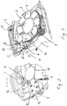
- eine perspektivische Ansicht der erfindungsgemäßen Vorrichtung, bei der die Mitnehmerscheibe, der bewegliche Hebel und ein Teil des Austrittsschachts zu sehen sind, und
- Fig. 2
- eine vergrößerte Ansicht des Kreisbereichs C nach
Fig. 1 .
- Fig. 1
- a perspective view of the device according to the invention, in which the drive plate, the movable lever and a part of the outlet shaft can be seen, and
- Fig. 2
- an enlarged view of the circular area C.
Fig. 1 ,
Die erfindungsgemäße Vorrichtung zum Vereinzeln und Ausgeben von Münzen weist als wesentlichen Bestandteil eine Mitnehmerscheibe 2 auf, die in einem Gehäuse 1 gelagert ist. In der
Die Mitnehmerscheibe 2 ist über ihren Umfang verteilt mit radial angeordneten Schienen 4 versehen, zwischen denen Mitnahmekammern 5 ausgebildet sind, die zum Transport der Münzen dienen. Mit Hilfe der Mitnahmekammern 5 werden daher Münzen, die in dem nicht dargestellten Sammelbehälter regellos und sortiert aufgenommen sind, bei Drehung der Mitnehmerscheibe 2 von den Schienen 4 mitgenommen und vom unteren Bereich der Mitnehmerscheibe 2 weg durch die Drehbewegung der Mitnehmerscheibe 2 nach oben transportiert bis sie auf ein Auswurfelement 6 treffen.The
Oberhalb der Mitnehmerscheibe 2 ist ein als Schnapphebel 7 bezeichneter beweglicher Hebel angeordnet, der im Gehäuse bzw. am Gehäuse 1 schwenkbar gelagert ist und in seiner Form in etwa einem Teil des Umfangs der Mitnehmerscheibe 2 folgt. Am Ende des Schnapphebels 7, das entgegengesetzt zu dem Lagerende des Schnapphebels 7 liegt, ist eine in Bezug auf den Schnapphebel 7 freidrehende Rolle 8 angeordnet. Zwischen Gehäuse 1 und Schnapphebel 7 ist eine Feder 15 eingesetzt, die den Schnapphebel 7 in eine Ruhestellung zwingt und bei Bewegung des Schnapphebels 7 gespannt wird.Above the
Weiterhin ist für den Betrachter schräg oberhalb der Mitnehmerscheibe 2 und des Auswurfelements 6 ein Austrittsschacht 9 positioniert, der im dargestellten Ausführungsbeispiel lediglich durch eine plattenförmige Begrenzungswand 10 repräsentiert ist, wobei die gegenüberliegende Wand in der Darstellung nicht zu sehen ist.Furthermore, for the viewer, an outlet shaft 9 is positioned obliquely above the
In bzw. an der Begrenzungswand 10 sind vier LEDs 11 befestigt, die ein Bestandteil von jeweiligen Lichtschranken sind, wobei der entsprechende Strahlungsempfänger, der den anderen Teil einer Lichtschranke bildet, an bzw. in der zur Begrenzungswand 10 gegenüberliegenden Wand des Austrittskanals 9 befestigt ist. Die LEDs 11 sind im vorliegenden Ausführungsbeispiel in Durchtrittsrichtung der Münze mit Abstand nebeneinanderliegend und quer zur Durchtrittsrichtung übereinanderliegend angeordnet. Die Lichtschranken, die durch die LEDs 11 repräsentiert sind, bilden eine erste Sensoranordnung, die die den Austrittskanal 9 durchlaufende Münze detektieren.Four
Weiterhin ist eine zweite Sensoranordnung vorgesehen, die aus einer Gabellichtschranke 12 und einem Unterbrecherelement 13 besteht. Die Gabellichtschranke 12 ist dabei auf der Begrenzungswand 10 befestigt und das Unterbrecherelement 13 ist im vorliegenden Fall einstückig mit dem Schnapphebel 7 verbunden. In
Schließlich ist eine nicht dargestellte Auswerteeinheit vorgesehen, die in dem Gehäuse 1 aufgenommen sein kann oder Bestandteil einer Steuervorrichtung ist, die beispielsweise eine Bezahleinrichtung steuert, wobei die erfindungsgemäße Vorrichtung eine Komponente der Bezahleinrichtung zum Zurückzahlen von Münzen sein kann. Die Auswerteeinheit empfängt die Signale der ersten und zweiten Sensoranordnung, respektive der Lichtschranken 11, 12 und wertet diese hinsichtlich ihrer zeitlichen Abfolge aus.Finally, an evaluation unit (not shown) is provided, which can be accommodated in the
Im Folgenden wird die Funktionsweise der erfindungsgemäßen Vorrichtung beschrieben. Wie ausgeführt, transportiert die Mitnehmerscheibe 2 in den Mitnehmerkammern 5 Münzen aus dem nicht dargestellten Sammelbehälter, wobei die Drehrichtung im dargestellten Beispiel entgegen dem Uhrzeigersinn ist. Die Drehrichtung kann, von der Steuervorrichtung, die die Abläufe der Vorrichtung steuert, umgekehrt werden. Wenn keine Münze in der Mitnehmerkammer 5 mitgeführt wird bzw. wenn die Mitnehmerscheibe nicht dreht, ist der Schnapphebel 7 in Ruhestellung, bei der das Unterbrecherelement 13 die Gabellichtschranke 12 unterbricht. Wenn eine von der Mitnehmerscheibe 2 geführte Münze, wie im dargestellten Beispiel, auf das Auswurfelement 6 trifft, wird es durch die Führungskante 14 des Auswurfelements 6 und die Schiene 4 bei der Drehbewegung der Mitnehmerscheibe 2 nach oben geschoben, wodurch der Schnapphebel 7 gegen die Feder 15, die gespannt wird, bewegt wird. Dabei rollt die freidrehende Rolle 8 auf dem Rand bzw. der Kante der Münze ab und das Unterbrecherelement 13 bewegt sich aus dem Bereich der Gabellichtschranke 12 heraus. Die Münze wird weiter in Richtung Eintritt des Austrittskanals 9 geschoben und wenn der Schnapphebel 7 bzw. die Rolle 8 über den Gipfelpunkt der Münze hinweg rollt, drückt die Federkraft der Feder 15 den Schnapphebel 7 nach unten, wodurch über die weiter auf der Kante abrollenden Rolle 8 eine Kraftkomponente auf die Münze ausgeübt wird, die zu dem Austrittskanal 9 gerichtet ist. Der bewegliche Hebel 7 bzw. die Rolle 8 schiebt somit die Münze weiter in Richtung des Austrittskanals, so dass sie durch diesen hindurch läuft. Beim Hindurchlaufen der Münzen werden die Lichtschranken der ersten Sensoranordnung, repräsentiert durch die LEDs 11, jeweils unterbrochen und die Signale werden entsprechend von der Auswerteeinheit empfangen. Diese wertet die Signale der Gabellichtschranke 12 und der Lichtschranken 11 hinsichtlich ihrer zeitlichen Abfolge aus, d.h. zuerst muss die Lichtschranke 12 ein Signal dahingehend abgeben, dass die Unterbrechung durch das Unterbrecherelement 13 aufgehoben ist. Dann werden nacheinander die in Durchtrittsrichtung liegenden Lichtschranken unterbrochen. Falls diese zeitliche Abfolge nicht so stattfindet, wie sie in der Auswerteeinheit vorgegeben ist, dann wird ein Fehlersignal von der Auswerteeinheit ausgegeben, in dessen Folge beispielsweise die Mitnehmerscheibe 2 gestoppt werden kann und die Auszahlung blockiert werden kann.The mode of operation of the device according to the invention is described below. As stated, the driving
Bei Hoppern nach dem Stand der Technik gibt es einen sogenannten Low-Level-Sensor, der als zwei Kontakte ausgebildet ist, die durch eine Münze geschlossen werden. Wird der Kontakt nicht geschlossen, wird angenommen, dass keine Münze mehr vorhanden ist und eine Auszahlung wird gestoppt bzw. die Vorrichtung abgeschaltet und der Sammelbehälter muss neu gefüllt werden. Häufig sind jedoch noch Münzen im Sammelbehälter, auch wenn der Low-Level-Sensor ein entsprechendes "Leersignal" abgibt.In the case of hoppers according to the prior art, there is a so-called low-level sensor which is designed as two contacts which are closed by a coin. If the contact is not closed, it is assumed that there is no coin left and payment is stopped or the device is switched off and the collection container has to be refilled. However, coins are often still in the collecting container, even if the low-level sensor emits a corresponding "empty signal".
Mit der erfindungsgemäßen Vorrichtung ist es bei Vorhandensein des Low-Level-Sensors nun möglich, das "Leersignal" als Vorwarnsignal für eine notwendige Auffüllung des Sammelbehälters zu nehmen und trotzdem weiter Münzen auszugeben, solange vorhanden. Falls die Gabellichtschranke 12 des Schnapphebels 7 dann feststellt, dass trotz Drehens der Mitnehmerscheibe nach einer bestimmten Zeit (Time-out) keine Münze mehr den Schnapphebel 7 auslenkt, wird ein Signal ausgelöst, dass der Sammelbehälter vollständig leer ist.With the device according to the invention, it is now possible, in the presence of the low-level sensor, to take the "empty signal" as a warning signal for a necessary filling of the collecting container and to continue to issue coins as long as available. If the
Diese beschriebene Funktion kann auch mit einem über die Steuervorrichtung eingebbaren Revisionsbefehl ausgelöst werden, bei der die Vorrichtung bis zur völligen "Leerzahlung" gefahren wird. Anschließend kann eine Zählwaage, die die Vorrichtung bzw. den Inhalt des Behälters wiegt und über die die im Behälter vorhandene Münzmenge bestimmt werden kann, auf "Null" gesetzt bzw. kalibriert werden.This described function can also be triggered with a revision command that can be entered via the control device, in which the device is moved to complete "empty payment". A counting scale, which weighs the device or the contents of the container and by means of which the amount of coins in the container can be determined, can then be set to "zero" or calibrated.
Schließlich ist es möglich, auf Befehl über die Steuervorrichtung festzustellen, ob grundsätzlich Münzen im Sammelbehälter vorhanden sind, wobei durch eine potentiell vorhandene Münze der Schnapphebel 7 bewegt wird und die Gabellichtschranke 12 die Bewegung detektiert, wodurch das Vorhandensein von Münzen festgestellt wird. Dann kann die Drehrichtung der Mitnehmerscheibe über die Steuervorrichtung umgekehrt werden und die Münze fällt in den Sammelbehälter zurück.Finally, it is possible, on command from the control device, to determine whether there are any coins in the collection container, the
Somit ermöglicht die erfindungsgemäße Vorrichtung unterschiedliche Prüfroutinen in Bezug auf "Erkennen von Münzen im Hopper".Thus, the device according to the invention enables different test routines with regard to "detection of coins in the hopper".
In der obigen Beschreibung wird von Münzen gesprochen, unter diesen Begriff sollen aber jede Art von für Bezahlvorgänge, Mietvorgänge, Spielvorgänge oder sonstige Vorgänge verwendeten Jetons, Chips oder sonstigen Scheiben fallen.Coins are referred to in the above description, but this term is intended to include any type of tokens, chips or other discs used for payment processes, rental processes, gaming processes or other processes.
Claims (9)
- A device for separating and dispensing coins, comprising a rotatably mounted carrier disk (2) and an ejection system for channeling a coin guided on the carrier disk (2) into a discharge shaft (9), in which a first sensor system (11) is arranged which registers the coin leaving the discharge shaft,
wherein the ejection system comprises a movable lever (7), which is designed, when the coin is channeled away from the carrier disk (2) into the discharge shaft (9), to be moved out of an idle position and, by being moved back into the idle position, to push the coin into the discharge shaft (9), a second sensor system (12, 13), which detects the movement of the movable lever (7) out of the idle position, being assigned to the movable lever (7), and an evaluation unit being provided, which is designed to correlate a movement signal, supplied by the second sensor system (12, 13), with at least one registration signal, supplied by the first sensor system (11), of the coin leaving the discharge shaft, and to emit an error signal when the two signals do not follow a predefined chronological sequence. - The device according to claim 1, characterized in that a spring (15), which is tensioned during the movement of the movable lever (7) out of the idle position and, during relaxation of the coin, exerts a movement component for the passage of the coin through the discharge shaft (9), is assigned to the movable lever (7).
- The device according to claim 1 or claim 2, characterized in that the movable lever (7) is arranged above the carrier disk (2) and, at the free end thereof, comprises a freely rotatable roller (8), which is designed to roll on the edge of a coin channeled into the discharge shaft (9).
- The device according to any one of claims 1 to 3, characterized in that the second sensor system comprises a light barrier (12), preferably a fork light barrier, and an interruption element (13) arranged on the movable lever (13).
- The device according to any one of claims 1 to 4, characterized in that the first sensor system comprises a plurality of light barriers (11), which are arranged next to one another in the passage direction of the coin and/or on top of one another transversely to this direction.
- The device according to any one of claims 1 to 5, characterized in that the evaluation unit is designed, in the case of a correct chronological sequence between the registration signal of the first sensor system (11) and the at least one movement signal of the second sensor system (12, 13), to activate a control unit for the disbursement of coins, and to stop the disbursement when the error signal occurs.
- The device according to any one of claims 1 to 6, characterized in that the carrier disk (2) comprises radially arranged rails (4) that are distributed over the circumference for catching coins.
- The device according to any one of claims 1 to 7, characterized in that the ejection system, in the region of the discharge shaft (9), comprises a guide element (6, 14) fixedly arranged over the carrier disk (2) for channeling a coin, in cooperation with one of the rails (4) radially arranged on the carrier disk (2), into the discharge shaft (9).
- The device according to any one of claims 1 to 8, characterized in that a control unit comprising the evaluation unit or connected thereto is provided, which reverses the carrier disk (2) the direction of rotation of the carrier disk upon detection of the movement signal by the second sensor system.
Applications Claiming Priority (1)
| Application Number | Priority Date | Filing Date | Title |
|---|---|---|---|
| DE202014005663.3U DE202014005663U1 (en) | 2014-07-08 | 2014-07-08 | Device for separating and dispensing coins |
Publications (2)
| Publication Number | Publication Date |
|---|---|
| EP2966626A1 EP2966626A1 (en) | 2016-01-13 |
| EP2966626B1 true EP2966626B1 (en) | 2020-01-01 |
Family
ID=53757972
Family Applications (1)
| Application Number | Title | Priority Date | Filing Date |
|---|---|---|---|
| EP15175740.8A Active EP2966626B1 (en) | 2014-07-08 | 2015-07-07 | Device for separating and dispensing coins |
Country Status (3)
| Country | Link |
|---|---|
| EP (1) | EP2966626B1 (en) |
| DE (1) | DE202014005663U1 (en) |
| ES (1) | ES2773288T3 (en) |
Families Citing this family (1)
| Publication number | Priority date | Publication date | Assignee | Title |
|---|---|---|---|---|
| DE202014005663U1 (en) | 2014-07-08 | 2015-10-09 | Walter Hanke Mechanische Werkstätten GmbH & Co. KG | Device for separating and dispensing coins |
Citations (8)
| Publication number | Priority date | Publication date | Assignee | Title |
|---|---|---|---|---|
| US6003651A (en) | 1997-11-13 | 1999-12-21 | International Game Technology | Sensing of coin output from a gaming device to reduce incorrect number of coins output |
| US20020072319A1 (en) | 2000-12-13 | 2002-06-13 | Hiroshi Abe | Detector unit for coin blockage in a coin dispenser |
| US6599180B2 (en) | 2001-04-05 | 2003-07-29 | Asahi Seiko Usa Inc. | Anti-theft coin monitoring sensor unit for a coin hopper dispenser |
| US20050003750A1 (en) | 2003-05-09 | 2005-01-06 | Yusuke Inuki | Dispensing coin hopper apparatus |
| US20060223428A1 (en) * | 2004-05-20 | 2006-10-05 | Aruze Corp. | Game media payout device for use in a game machine |
| US7628685B2 (en) | 2006-10-12 | 2009-12-08 | Asahi Seiko Co., Ltd. | Coin hopper |
| US7987961B2 (en) | 2005-10-14 | 2011-08-02 | Money Controls Limited | Coin dispensing apparatus |
| DE202014005663U1 (en) | 2014-07-08 | 2015-10-09 | Walter Hanke Mechanische Werkstätten GmbH & Co. KG | Device for separating and dispensing coins |
Family Cites Families (2)
| Publication number | Priority date | Publication date | Assignee | Title |
|---|---|---|---|---|
| JP4470020B2 (en) * | 1999-06-09 | 2010-06-02 | 旭精工株式会社 | Coin release guide for hopper device |
| ITBO20080448A1 (en) * | 2008-07-14 | 2010-01-15 | Alberici S P A | DISPENSER AND COIN METER DEVICE |
-
2014
- 2014-07-08 DE DE202014005663.3U patent/DE202014005663U1/en active Active
-
2015
- 2015-07-07 ES ES15175740T patent/ES2773288T3/en active Active
- 2015-07-07 EP EP15175740.8A patent/EP2966626B1/en active Active
Patent Citations (8)
| Publication number | Priority date | Publication date | Assignee | Title |
|---|---|---|---|---|
| US6003651A (en) | 1997-11-13 | 1999-12-21 | International Game Technology | Sensing of coin output from a gaming device to reduce incorrect number of coins output |
| US20020072319A1 (en) | 2000-12-13 | 2002-06-13 | Hiroshi Abe | Detector unit for coin blockage in a coin dispenser |
| US6599180B2 (en) | 2001-04-05 | 2003-07-29 | Asahi Seiko Usa Inc. | Anti-theft coin monitoring sensor unit for a coin hopper dispenser |
| US20050003750A1 (en) | 2003-05-09 | 2005-01-06 | Yusuke Inuki | Dispensing coin hopper apparatus |
| US20060223428A1 (en) * | 2004-05-20 | 2006-10-05 | Aruze Corp. | Game media payout device for use in a game machine |
| US7987961B2 (en) | 2005-10-14 | 2011-08-02 | Money Controls Limited | Coin dispensing apparatus |
| US7628685B2 (en) | 2006-10-12 | 2009-12-08 | Asahi Seiko Co., Ltd. | Coin hopper |
| DE202014005663U1 (en) | 2014-07-08 | 2015-10-09 | Walter Hanke Mechanische Werkstätten GmbH & Co. KG | Device for separating and dispensing coins |
Non-Patent Citations (2)
| Title |
|---|
| "ccTalk Flow Hopper Product code "XXXX-USE_SERNR"Model: 18-USE_SERNR-IDProduct Manual", CCTALK FLOW HOPPER PRODUCT CODE "XXXX-USE_SERNR"MODEL: 18-USE_SERNR-IDPRODUCT MANUAL, January 0421 (0421-01-01), XP055744572 |
| MATTHIAS HERRMANN: "Parallel Flow Hopper Model: 18-ParallelProduct Manual", PARALLEL FLOW HOPPER MODEL: 18-PARALLELPRODUCT MANUAL, XP055744573 |
Also Published As
| Publication number | Publication date |
|---|---|
| ES2773288T3 (en) | 2020-07-10 |
| EP2966626A1 (en) | 2016-01-13 |
| DE202014005663U1 (en) | 2015-10-09 |
Similar Documents
| Publication | Publication Date | Title |
|---|---|---|
| DE2645367C2 (en) | Device for separating coins | |
| DE2737352A1 (en) | COIN SORTING DEVICE | |
| DE19739459A1 (en) | POS terminal | |
| EP2695145B1 (en) | Apparatus and method for sorting coins | |
| DE4123549C3 (en) | Coin sorter | |
| EP2897104B1 (en) | Coin separation system | |
| DE3924247C2 (en) | Coin acceptance and dispensing machine | |
| EP2720200B1 (en) | Coin sorting apparatus | |
| DE2120353C3 (en) | Device for separating coins, discs or the like. at a sorting and payment machine | |
| DE2800494C3 (en) | Coin sorting device with ejector plungers | |
| EP2720202B1 (en) | Coin sorting apparatus | |
| DE3929462C3 (en) | Coin separating device for a coin sorting and counting device | |
| EP2966626B1 (en) | Device for separating and dispensing coins | |
| EP2765559A1 (en) | Coin sorting apparatus | |
| EP3654301B1 (en) | Device for separating, testing and dispensing coins | |
| EP2252977B1 (en) | Insertion device for coins | |
| EP2672467B1 (en) | Device for separating coins with a paddle wheel arranged in front of a gap | |
| DE10132180A1 (en) | Machine for aligning capsules has sorting roller pivot-mounted on horizontal axle, with inner and outer periphery, and two stationary deflector elements | |
| DE102008025976B4 (en) | coin sorter | |
| DE19921570A1 (en) | Processing system for banknotes | |
| DE102010055700A1 (en) | Device for measuring length of sheet material e.g. banknote, has evaluation device that is adapted to evaluate the sensed signal output by line sensor | |
| EP1785949B1 (en) | Coin sorting apparatus | |
| EP2355054B1 (en) | Coin sorting apparatus and check out systems | |
| DE19705700A1 (en) | Drinks container or can recycling device | |
| DE102011001872A1 (en) | Device for handling coins to perform coin recycling process, has coins sliding to support surface of support element of sorting unit and supplied through openings of receptacle depending on diameter of coins |
Legal Events
| Date | Code | Title | Description |
|---|---|---|---|
| PUAI | Public reference made under article 153(3) epc to a published international application that has entered the european phase |
Free format text: ORIGINAL CODE: 0009012 |
|
| AK | Designated contracting states |
Kind code of ref document: A1 Designated state(s): AL AT BE BG CH CY CZ DE DK EE ES FI FR GB GR HR HU IE IS IT LI LT LU LV MC MK MT NL NO PL PT RO RS SE SI SK SM TR |
|
| AX | Request for extension of the european patent |
Extension state: BA ME |
|
| 17P | Request for examination filed |
Effective date: 20160713 |
|
| RBV | Designated contracting states (corrected) |
Designated state(s): AL AT BE BG CH CY CZ DE DK EE ES FI FR GB GR HR HU IE IS IT LI LT LU LV MC MK MT NL NO PL PT RO RS SE SI SK SM TR |
|
| GRAP | Despatch of communication of intention to grant a patent |
Free format text: ORIGINAL CODE: EPIDOSNIGR1 |
|
| STAA | Information on the status of an ep patent application or granted ep patent |
Free format text: STATUS: GRANT OF PATENT IS INTENDED |
|
| INTG | Intention to grant announced |
Effective date: 20190718 |
|
| GRAS | Grant fee paid |
Free format text: ORIGINAL CODE: EPIDOSNIGR3 |
|
| GRAA | (expected) grant |
Free format text: ORIGINAL CODE: 0009210 |
|
| STAA | Information on the status of an ep patent application or granted ep patent |
Free format text: STATUS: THE PATENT HAS BEEN GRANTED |
|
| AK | Designated contracting states |
Kind code of ref document: B1 Designated state(s): AL AT BE BG CH CY CZ DE DK EE ES FI FR GB GR HR HU IE IS IT LI LT LU LV MC MK MT NL NO PL PT RO RS SE SI SK SM TR |
|
| REG | Reference to a national code |
Ref country code: GB Ref legal event code: FG4D Free format text: NOT ENGLISH |
|
| REG | Reference to a national code |
Ref country code: AT Ref legal event code: REF Ref document number: 1220768 Country of ref document: AT Kind code of ref document: T Effective date: 20200115 Ref country code: CH Ref legal event code: EP |
|
| REG | Reference to a national code |
Ref country code: DE Ref legal event code: R096 Ref document number: 502015011371 Country of ref document: DE |
|
| REG | Reference to a national code |
Ref country code: IE Ref legal event code: FG4D Free format text: LANGUAGE OF EP DOCUMENT: GERMAN |
|
| REG | Reference to a national code |
Ref country code: NL Ref legal event code: MP Effective date: 20200101 |
|
| REG | Reference to a national code |
Ref country code: LT Ref legal event code: MG4D Ref country code: ES Ref legal event code: FG2A Ref document number: 2773288 Country of ref document: ES Kind code of ref document: T3 Effective date: 20200710 |
|
| PG25 | Lapsed in a contracting state [announced via postgrant information from national office to epo] |
Ref country code: PT Free format text: LAPSE BECAUSE OF FAILURE TO SUBMIT A TRANSLATION OF THE DESCRIPTION OR TO PAY THE FEE WITHIN THE PRESCRIBED TIME-LIMIT Effective date: 20200527 Ref country code: CZ Free format text: LAPSE BECAUSE OF FAILURE TO SUBMIT A TRANSLATION OF THE DESCRIPTION OR TO PAY THE FEE WITHIN THE PRESCRIBED TIME-LIMIT Effective date: 20200101 Ref country code: NL Free format text: LAPSE BECAUSE OF FAILURE TO SUBMIT A TRANSLATION OF THE DESCRIPTION OR TO PAY THE FEE WITHIN THE PRESCRIBED TIME-LIMIT Effective date: 20200101 Ref country code: LT Free format text: LAPSE BECAUSE OF FAILURE TO SUBMIT A TRANSLATION OF THE DESCRIPTION OR TO PAY THE FEE WITHIN THE PRESCRIBED TIME-LIMIT Effective date: 20200101 Ref country code: NO Free format text: LAPSE BECAUSE OF FAILURE TO SUBMIT A TRANSLATION OF THE DESCRIPTION OR TO PAY THE FEE WITHIN THE PRESCRIBED TIME-LIMIT Effective date: 20200401 Ref country code: FI Free format text: LAPSE BECAUSE OF FAILURE TO SUBMIT A TRANSLATION OF THE DESCRIPTION OR TO PAY THE FEE WITHIN THE PRESCRIBED TIME-LIMIT Effective date: 20200101 Ref country code: RS Free format text: LAPSE BECAUSE OF FAILURE TO SUBMIT A TRANSLATION OF THE DESCRIPTION OR TO PAY THE FEE WITHIN THE PRESCRIBED TIME-LIMIT Effective date: 20200101 |
|
| PG25 | Lapsed in a contracting state [announced via postgrant information from national office to epo] |
Ref country code: HR Free format text: LAPSE BECAUSE OF FAILURE TO SUBMIT A TRANSLATION OF THE DESCRIPTION OR TO PAY THE FEE WITHIN THE PRESCRIBED TIME-LIMIT Effective date: 20200101 Ref country code: GR Free format text: LAPSE BECAUSE OF FAILURE TO SUBMIT A TRANSLATION OF THE DESCRIPTION OR TO PAY THE FEE WITHIN THE PRESCRIBED TIME-LIMIT Effective date: 20200402 Ref country code: BG Free format text: LAPSE BECAUSE OF FAILURE TO SUBMIT A TRANSLATION OF THE DESCRIPTION OR TO PAY THE FEE WITHIN THE PRESCRIBED TIME-LIMIT Effective date: 20200401 Ref country code: LV Free format text: LAPSE BECAUSE OF FAILURE TO SUBMIT A TRANSLATION OF THE DESCRIPTION OR TO PAY THE FEE WITHIN THE PRESCRIBED TIME-LIMIT Effective date: 20200101 Ref country code: SE Free format text: LAPSE BECAUSE OF FAILURE TO SUBMIT A TRANSLATION OF THE DESCRIPTION OR TO PAY THE FEE WITHIN THE PRESCRIBED TIME-LIMIT Effective date: 20200101 Ref country code: IS Free format text: LAPSE BECAUSE OF FAILURE TO SUBMIT A TRANSLATION OF THE DESCRIPTION OR TO PAY THE FEE WITHIN THE PRESCRIBED TIME-LIMIT Effective date: 20200501 |
|
| REG | Reference to a national code |
Ref country code: DE Ref legal event code: R026 Ref document number: 502015011371 Country of ref document: DE |
|
| PLBI | Opposition filed |
Free format text: ORIGINAL CODE: 0009260 |
|
| PLAX | Notice of opposition and request to file observation + time limit sent |
Free format text: ORIGINAL CODE: EPIDOSNOBS2 |
|
| PG25 | Lapsed in a contracting state [announced via postgrant information from national office to epo] |
Ref country code: EE Free format text: LAPSE BECAUSE OF FAILURE TO SUBMIT A TRANSLATION OF THE DESCRIPTION OR TO PAY THE FEE WITHIN THE PRESCRIBED TIME-LIMIT Effective date: 20200101 Ref country code: DK Free format text: LAPSE BECAUSE OF FAILURE TO SUBMIT A TRANSLATION OF THE DESCRIPTION OR TO PAY THE FEE WITHIN THE PRESCRIBED TIME-LIMIT Effective date: 20200101 Ref country code: RO Free format text: LAPSE BECAUSE OF FAILURE TO SUBMIT A TRANSLATION OF THE DESCRIPTION OR TO PAY THE FEE WITHIN THE PRESCRIBED TIME-LIMIT Effective date: 20200101 Ref country code: SK Free format text: LAPSE BECAUSE OF FAILURE TO SUBMIT A TRANSLATION OF THE DESCRIPTION OR TO PAY THE FEE WITHIN THE PRESCRIBED TIME-LIMIT Effective date: 20200101 Ref country code: SM Free format text: LAPSE BECAUSE OF FAILURE TO SUBMIT A TRANSLATION OF THE DESCRIPTION OR TO PAY THE FEE WITHIN THE PRESCRIBED TIME-LIMIT Effective date: 20200101 |
|
| 26 | Opposition filed |
Opponent name: CRANE PAYMENT INNOVATIONS, INC. Effective date: 20200929 |
|
| PLBB | Reply of patent proprietor to notice(s) of opposition received |
Free format text: ORIGINAL CODE: EPIDOSNOBS3 |
|
| PG25 | Lapsed in a contracting state [announced via postgrant information from national office to epo] |
Ref country code: MC Free format text: LAPSE BECAUSE OF FAILURE TO SUBMIT A TRANSLATION OF THE DESCRIPTION OR TO PAY THE FEE WITHIN THE PRESCRIBED TIME-LIMIT Effective date: 20200101 Ref country code: PL Free format text: LAPSE BECAUSE OF FAILURE TO SUBMIT A TRANSLATION OF THE DESCRIPTION OR TO PAY THE FEE WITHIN THE PRESCRIBED TIME-LIMIT Effective date: 20200101 Ref country code: SI Free format text: LAPSE BECAUSE OF FAILURE TO SUBMIT A TRANSLATION OF THE DESCRIPTION OR TO PAY THE FEE WITHIN THE PRESCRIBED TIME-LIMIT Effective date: 20200101 |
|
| REG | Reference to a national code |
Ref country code: CH Ref legal event code: PL |
|
| REG | Reference to a national code |
Ref country code: BE Ref legal event code: MM Effective date: 20200731 |
|
| PG25 | Lapsed in a contracting state [announced via postgrant information from national office to epo] |
Ref country code: FR Free format text: LAPSE BECAUSE OF NON-PAYMENT OF DUE FEES Effective date: 20200731 Ref country code: LU Free format text: LAPSE BECAUSE OF NON-PAYMENT OF DUE FEES Effective date: 20200707 Ref country code: LI Free format text: LAPSE BECAUSE OF NON-PAYMENT OF DUE FEES Effective date: 20200731 Ref country code: CH Free format text: LAPSE BECAUSE OF NON-PAYMENT OF DUE FEES Effective date: 20200731 Ref country code: IE Free format text: LAPSE BECAUSE OF NON-PAYMENT OF DUE FEES Effective date: 20200707 |
|
| PG25 | Lapsed in a contracting state [announced via postgrant information from national office to epo] |
Ref country code: BE Free format text: LAPSE BECAUSE OF NON-PAYMENT OF DUE FEES Effective date: 20200731 |
|
| REG | Reference to a national code |
Ref country code: AT Ref legal event code: MM01 Ref document number: 1220768 Country of ref document: AT Kind code of ref document: T Effective date: 20200707 |
|
| PG25 | Lapsed in a contracting state [announced via postgrant information from national office to epo] |
Ref country code: AT Free format text: LAPSE BECAUSE OF NON-PAYMENT OF DUE FEES Effective date: 20200707 |
|
| REG | Reference to a national code |
Ref country code: CH Ref legal event code: PK Free format text: BERICHTIGUNGEN |
|
| RIC2 | Information provided on ipc code assigned after grant |
Ipc: G07D 9/00 20060101ALI20220215BHEP Ipc: G07D 1/00 20060101AFI20220215BHEP |
|
| APBM | Appeal reference recorded |
Free format text: ORIGINAL CODE: EPIDOSNREFNO |
|
| APBP | Date of receipt of notice of appeal recorded |
Free format text: ORIGINAL CODE: EPIDOSNNOA2O |
|
| APAH | Appeal reference modified |
Free format text: ORIGINAL CODE: EPIDOSCREFNO |
|
| PG25 | Lapsed in a contracting state [announced via postgrant information from national office to epo] |
Ref country code: TR Free format text: LAPSE BECAUSE OF FAILURE TO SUBMIT A TRANSLATION OF THE DESCRIPTION OR TO PAY THE FEE WITHIN THE PRESCRIBED TIME-LIMIT Effective date: 20200101 Ref country code: MT Free format text: LAPSE BECAUSE OF FAILURE TO SUBMIT A TRANSLATION OF THE DESCRIPTION OR TO PAY THE FEE WITHIN THE PRESCRIBED TIME-LIMIT Effective date: 20200101 Ref country code: CY Free format text: LAPSE BECAUSE OF FAILURE TO SUBMIT A TRANSLATION OF THE DESCRIPTION OR TO PAY THE FEE WITHIN THE PRESCRIBED TIME-LIMIT Effective date: 20200101 |
|
| PG25 | Lapsed in a contracting state [announced via postgrant information from national office to epo] |
Ref country code: MK Free format text: LAPSE BECAUSE OF FAILURE TO SUBMIT A TRANSLATION OF THE DESCRIPTION OR TO PAY THE FEE WITHIN THE PRESCRIBED TIME-LIMIT Effective date: 20200101 Ref country code: AL Free format text: LAPSE BECAUSE OF FAILURE TO SUBMIT A TRANSLATION OF THE DESCRIPTION OR TO PAY THE FEE WITHIN THE PRESCRIBED TIME-LIMIT Effective date: 20200101 |
|
| APBQ | Date of receipt of statement of grounds of appeal recorded |
Free format text: ORIGINAL CODE: EPIDOSNNOA3O |
|
| PLAB | Opposition data, opponent's data or that of the opponent's representative modified |
Free format text: ORIGINAL CODE: 0009299OPPO |
|
| R26 | Opposition filed (corrected) |
Opponent name: CRANE PAYMENT INNOVATIONS, INC. Effective date: 20200929 |
|
| PGFP | Annual fee paid to national office [announced via postgrant information from national office to epo] |
Ref country code: IT Payment date: 20230724 Year of fee payment: 9 Ref country code: GB Payment date: 20230720 Year of fee payment: 9 Ref country code: ES Payment date: 20230926 Year of fee payment: 9 |
|
| PGFP | Annual fee paid to national office [announced via postgrant information from national office to epo] |
Ref country code: DE Payment date: 20230721 Year of fee payment: 9 |