EP2966271B1 - Turbinengehäuse eines turboladers - Google Patents
Turbinengehäuse eines turboladers Download PDFInfo
- Publication number
- EP2966271B1 EP2966271B1 EP15170747.8A EP15170747A EP2966271B1 EP 2966271 B1 EP2966271 B1 EP 2966271B1 EP 15170747 A EP15170747 A EP 15170747A EP 2966271 B1 EP2966271 B1 EP 2966271B1
- Authority
- EP
- European Patent Office
- Prior art keywords
- coolant
- wastegate
- turbine housing
- spiral
- passage
- Prior art date
- Legal status (The legal status is an assumption and is not a legal conclusion. Google has not performed a legal analysis and makes no representation as to the accuracy of the status listed.)
- Active
Links
Images



Classifications
-
- F—MECHANICAL ENGINEERING; LIGHTING; HEATING; WEAPONS; BLASTING
- F01—MACHINES OR ENGINES IN GENERAL; ENGINE PLANTS IN GENERAL; STEAM ENGINES
- F01D—NON-POSITIVE DISPLACEMENT MACHINES OR ENGINES, e.g. STEAM TURBINES
- F01D25/00—Component parts, details, or accessories, not provided for in, or of interest apart from, other groups
- F01D25/08—Cooling; Heating; Heat-insulation
- F01D25/14—Casings modified therefor
-
- F—MECHANICAL ENGINEERING; LIGHTING; HEATING; WEAPONS; BLASTING
- F01—MACHINES OR ENGINES IN GENERAL; ENGINE PLANTS IN GENERAL; STEAM ENGINES
- F01D—NON-POSITIVE DISPLACEMENT MACHINES OR ENGINES, e.g. STEAM TURBINES
- F01D25/00—Component parts, details, or accessories, not provided for in, or of interest apart from, other groups
- F01D25/08—Cooling; Heating; Heat-insulation
- F01D25/12—Cooling
-
- F—MECHANICAL ENGINEERING; LIGHTING; HEATING; WEAPONS; BLASTING
- F01—MACHINES OR ENGINES IN GENERAL; ENGINE PLANTS IN GENERAL; STEAM ENGINES
- F01D—NON-POSITIVE DISPLACEMENT MACHINES OR ENGINES, e.g. STEAM TURBINES
- F01D25/00—Component parts, details, or accessories, not provided for in, or of interest apart from, other groups
- F01D25/24—Casings; Casing parts, e.g. diaphragms, casing fastenings
-
- F—MECHANICAL ENGINEERING; LIGHTING; HEATING; WEAPONS; BLASTING
- F01—MACHINES OR ENGINES IN GENERAL; ENGINE PLANTS IN GENERAL; STEAM ENGINES
- F01D—NON-POSITIVE DISPLACEMENT MACHINES OR ENGINES, e.g. STEAM TURBINES
- F01D25/00—Component parts, details, or accessories, not provided for in, or of interest apart from, other groups
- F01D25/28—Supporting or mounting arrangements, e.g. for turbine casing
-
- F—MECHANICAL ENGINEERING; LIGHTING; HEATING; WEAPONS; BLASTING
- F01—MACHINES OR ENGINES IN GENERAL; ENGINE PLANTS IN GENERAL; STEAM ENGINES
- F01D—NON-POSITIVE DISPLACEMENT MACHINES OR ENGINES, e.g. STEAM TURBINES
- F01D9/00—Stators
- F01D9/02—Nozzles; Nozzle boxes; Stator blades; Guide conduits, e.g. individual nozzles
- F01D9/026—Scrolls for radial machines or engines
-
- F—MECHANICAL ENGINEERING; LIGHTING; HEATING; WEAPONS; BLASTING
- F02—COMBUSTION ENGINES; HOT-GAS OR COMBUSTION-PRODUCT ENGINE PLANTS
- F02B—INTERNAL-COMBUSTION PISTON ENGINES; COMBUSTION ENGINES IN GENERAL
- F02B39/00—Component parts, details, or accessories relating to, driven charging or scavenging pumps, not provided for in groups F02B33/00 - F02B37/00
- F02B39/16—Other safety measures for, or other control of, pumps
-
- F—MECHANICAL ENGINEERING; LIGHTING; HEATING; WEAPONS; BLASTING
- F02—COMBUSTION ENGINES; HOT-GAS OR COMBUSTION-PRODUCT ENGINE PLANTS
- F02C—GAS-TURBINE PLANTS; AIR INTAKES FOR JET-PROPULSION PLANTS; CONTROLLING FUEL SUPPLY IN AIR-BREATHING JET-PROPULSION PLANTS
- F02C6/00—Plural gas-turbine plants; Combinations of gas-turbine plants with other apparatus; Adaptations of gas-turbine plants for special use
- F02C6/04—Gas-turbine plants providing heated or pressurised working fluid for other apparatus, e.g. without mechanical power output
- F02C6/10—Gas-turbine plants providing heated or pressurised working fluid for other apparatus, e.g. without mechanical power output supplying working fluid to a user, e.g. a chemical process, which returns working fluid to a turbine of the plant
- F02C6/12—Turbochargers, i.e. plants for augmenting mechanical power output of internal-combustion piston engines by increase of charge pressure
-
- F—MECHANICAL ENGINEERING; LIGHTING; HEATING; WEAPONS; BLASTING
- F02—COMBUSTION ENGINES; HOT-GAS OR COMBUSTION-PRODUCT ENGINE PLANTS
- F02B—INTERNAL-COMBUSTION PISTON ENGINES; COMBUSTION ENGINES IN GENERAL
- F02B39/00—Component parts, details, or accessories relating to, driven charging or scavenging pumps, not provided for in groups F02B33/00 - F02B37/00
- F02B39/16—Other safety measures for, or other control of, pumps
- F02B2039/162—Control of pump parameters to improve safety thereof
- F02B2039/164—Control of pump parameters to improve safety thereof the temperature of the pump, of the pump drive or the pumped fluid being limited
-
- F—MECHANICAL ENGINEERING; LIGHTING; HEATING; WEAPONS; BLASTING
- F05—INDEXING SCHEMES RELATING TO ENGINES OR PUMPS IN VARIOUS SUBCLASSES OF CLASSES F01-F04
- F05D—INDEXING SCHEME FOR ASPECTS RELATING TO NON-POSITIVE-DISPLACEMENT MACHINES OR ENGINES, GAS-TURBINES OR JET-PROPULSION PLANTS
- F05D2220/00—Application
- F05D2220/40—Application in turbochargers
-
- F—MECHANICAL ENGINEERING; LIGHTING; HEATING; WEAPONS; BLASTING
- F05—INDEXING SCHEMES RELATING TO ENGINES OR PUMPS IN VARIOUS SUBCLASSES OF CLASSES F01-F04
- F05D—INDEXING SCHEME FOR ASPECTS RELATING TO NON-POSITIVE-DISPLACEMENT MACHINES OR ENGINES, GAS-TURBINES OR JET-PROPULSION PLANTS
- F05D2240/00—Components
- F05D2240/10—Stators
- F05D2240/14—Casings or housings protecting or supporting assemblies within
-
- F—MECHANICAL ENGINEERING; LIGHTING; HEATING; WEAPONS; BLASTING
- F05—INDEXING SCHEMES RELATING TO ENGINES OR PUMPS IN VARIOUS SUBCLASSES OF CLASSES F01-F04
- F05D—INDEXING SCHEME FOR ASPECTS RELATING TO NON-POSITIVE-DISPLACEMENT MACHINES OR ENGINES, GAS-TURBINES OR JET-PROPULSION PLANTS
- F05D2300/00—Materials; Properties thereof
- F05D2300/60—Properties or characteristics given to material by treatment or manufacturing
- F05D2300/603—Composites; e.g. fibre-reinforced
Definitions
- Subject matter disclosed herein relates generally to turbomachinery for internal combustion engines and, in particular, to turbine housings.
- the internal combustion engine 110 includes an engine block 118 housing one or more combustion chambers that operatively drive a shaft 112 (e.g., via pistons) as well as an intake port 114 that provides a flow path for air to the engine block 118 and an exhaust port 116 that provides a flow path for exhaust from the engine block 118.
- the turbocharger 120 can act to extract energy from the exhaust and to provide energy to intake air, which may be combined with fuel to form combustion gas.
- the turbocharger 120 includes an air inlet 134, a shaft 122, a compressor housing assembly 124 for a compressor wheel 125, a turbine housing assembly 126 for a turbine wheel 127, another housing assembly 128 and an exhaust outlet 136.
- the housing 128 may be referred to as a center housing assembly as it is disposed between the compressor housing assembly 124 and the turbine housing assembly 126.
- the shaft 122 may be a shaft assembly that includes a variety of components.
- the shaft 122 may be rotatably supported by a bearing system (e.g., journal bearing(s), rolling element bearing(s), etc.) disposed in the housing assembly 128 (e.g., in a bore defined by one or more bore walls) such that rotation of the turbine wheel 127 causes rotation of the compressor wheel 125 (e.g., as rotatably coupled by the shaft 122).
- a center housing rotating assembly can include the compressor wheel 125, the turbine wheel 127, the shaft 122, the housing assembly 128 and various other components (e.g., a compressor side plate disposed at an axial location between the compressor wheel 125 and the housing assembly 128).
- variable geometry assembly 129 is shown as being, in part, disposed between the housing assembly 128 and the housing assembly 126.
- a variable geometry assembly may include vanes or other components to vary geometry of passages that lead to a turbine wheel space in the turbine housing assembly 126.
- a variable geometry compressor assembly may be provided.
- a wastegate valve (or simply wastegate) 135 is positioned proximate to an exhaust inlet of the turbine housing assembly 126.
- the wastegate valve 135 can be controlled to allow at least some exhaust from the exhaust port 116 to bypass the turbine wheel 127.
- Various wastegates, wastegate components, etc. may be applied to a conventional fixed nozzle turbine, a fixed-vaned nozzle turbine, a variable nozzle turbine, a twin scroll turbocharger, etc.
- an exhaust gas recirculation (EGR) conduit 115 is also shown, which may be provided, optionally with one or more valves 117, for example, to allow exhaust to flow to a position upstream the compressor wheel 125.
- EGR exhaust gas recirculation
- Fig. 1 also shows an example arrangement 150 for flow of exhaust to an exhaust turbine housing assembly 152 and another example arrangement 170 for flow of exhaust to an exhaust turbine housing assembly 172.
- a cylinder head 154 includes passages 156 within to direct exhaust from cylinders to the turbine housing assembly 152 while in the arrangement 170, a manifold 176 provides for mounting of the turbine housing assembly 172, for example, without any separate, intermediate length of exhaust piping.
- the turbine housing assemblies 152 and 172 may be configured for use with a wastegate, variable geometry assembly, etc.
- a controller 190 is shown as including one or more processors 192, memory 194 and one or more interfaces 196.
- a controller may include circuitry such as circuitry of an engine control unit (ECU).
- ECU engine control unit
- various methods or techniques may optionally be implemented in conjunction with a controller, for example, through control logic.
- Control logic may depend on one or more engine operating conditions (e.g., turbo rpm, engine rpm, temperature, load, lubricant, cooling, etc.).
- sensors may transmit information to the controller 190 via the one or more interfaces 196.
- Control logic may rely on such information and, in turn, the controller 190 may output control signals to control engine operation.
- the controller 190 may be configured to control lubricant flow, temperature, a variable geometry assembly (e.g., variable geometry compressor or turbine), a wastegate (e.g., via an actuator), an electric motor, or one or more other components associated with an engine, a turbocharger (or turbochargers), etc.
- a variable geometry assembly e.g., variable geometry compressor or turbine
- a wastegate e.g., via an actuator
- an electric motor e.g., via an actuator
- an electric motor e.g., via an actuator
- turbocharger or turbochargers
- the turbocharger 120 may include one or more actuators and/or one or more sensors 198 that may be, for example, coupled to an interface or interfaces 196 of the controller 190.
- the wastegate 135 may be controlled by a controller that includes an actuator responsive to an electrical signal, a pressure signal, etc.
- an actuator for a wastegate may be a mechanical actuator, for example, that may operate without a need for electrical power (e.g., consider a mechanical actuator configured to respond to a pressure signal supplied via a conduit).
- An internal wastegate may be integrated at least partially into a turbine housing and, for example, include a flapper valve (e.g., a plug), a crank arm, a shaft or rod, and an actuator.
- a plug of a wastegate may include a surface that is configured to seat against a seat disposed about an exhaust bypass opening (e.g., a valve seat or wastegate seat).
- a wastegate plug In a closed position, a wastegate plug should be seated against a wastegate seat (e.g., seating surface) with sufficient force to effectively seal an exhaust bypass opening (e.g., to prevent leaking of exhaust from a high pressure exhaust supply to a lower pressure region).
- a wastegate seat e.g., seating surface
- an exhaust bypass opening e.g., to prevent leaking of exhaust from a high pressure exhaust supply to a lower pressure region.
- High load requirements may generate high mechanical stresses in a wastegate's kinematics components, a fact which has led in some instances to significantly oversized component design to meet reliability levels (e.g., as demanded by engine manufacturers). Reliability of wastegate components for gasoline engine applications is particularly important where operational temperatures and exhaust pulsation levels can be quite high (e.g., up to about 1000 degrees C or more).
- a turbine housing may be a cast component that includes passages for flow of fluid, which may be used, for example, to extract heat energy to thereby cool the turbine housing.
- a turbine housing that includes passages for flow of water and/or other coolant.
- the turbine housing may be fabricated from a desired material or materials (e.g., lower temperature materials, lower weight materials, etc.).
- a turbine housing with coolant passages may radiate less heat in an engine compartment, may allow for heat recovery (e.g., energy management), may improve engine cold start behavior, may increase performance (e.g., fuel consumption, etc.) and may offer possible cost reductions.
- a turbine housing may be made of aluminum, which may be an aluminum alloy.
- a weight reduction may be realized compared to a turbine housing made of a similar volume of material that has a higher density.
- a coolant core may be a serpentine core that can be used in a casting process to impart coolant passages to a cast turbine housing.
- Such an approach may provide for relatively stable and relatively uniform heat removal.
- a heat transfer exchange ratio may be achieved while keeping coolant flow associated pressure drop under control (e.g., to within one or more targets).
- a coolant core may include features that may mitigate risks of core cracking or displacement during pouring, which could possible lead to detrimental issues such as, for example, casting quality, scrap rate (e.g., due to cases where wall thickness between core may be too small or even with cracks), tool damage, etc.
- a coolant core may include one or more backbone features, for example, consider a rib and backbone construction (e.g., with one or more backbones and one or more ribs).
- a coolant core may include one or more casting features, for example, consider a restricted channel, which may increase resistance and stability of the core during pouring.
- a backbone approach may help to control non-desired bypasses and recirculation, which may minimize impact of additional dead volume(s) on fluid dynamic behavior.
- a backbone approach to a coolant core may provide for formation of a turbine housing with coolant passages that can be adequately flushed and that can provide for adequate heat transfer.
- a coolant core may be provides with rigidizing features, for example, that impart structural stability to facilitate casting of a turbine housing with coolant passages.
- features may provide a desired design of one or more recesses with limited undesirable direct bypass(es), for example, to achieve a desired level of heat removal.
- a coolant core may be configured to impart coolant passages to one or more particular regions.
- One or more cores may be used in a casting process to cast a housing where, for example, passages in the housing may be created in a negative manner with respect to positive features of at least one core.
- a casting process may be a gravity-pour sand casting process.
- a housing may be made of hardened molten material (e.g., metal, alloy, etc.) that is shaped at least in part by at least one core.
- a core may be made of compacted sand, which may be disintegrated and removed from a cast housing after the material forming the cast housing has solidified and cooled.
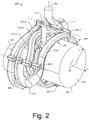
- Fig. 2 shows an example of an assembly 200 that includes a central core 202 and a coolant passage core 204.
- the central core 202 includes a volute forming portion 205, an inlet portion 211, a wastegate shaft bore portion 215, a turbine wheel opening portion 241 and an outlet portion 251.
- the coolant passage core 204 includes a spiral tubular portion 207 that extends from end 271 to end 281 that is supported by a plurality of members 265-1, 265-2 and 265-3.
- Fig. 2 also shows the central core 202 as including an outlet axis (z o ); noting that the central core 202 may also include an inlet axis (e.g., z in ). Positions of the spiral tubular portion 207 and the members 265-1, 265-2 and 265-3 may be defined with respect to one or more axes of the central core 202.
- the spiral tubular portion 207 can include a plurality of windings 275-1, 275-2, 275-3 and 275-4 where each of the windings 275-1, 275-2, 275-3 and 275-4 may be supported by at least one of the plurality of members 265-1, 265-2 and 265-3.
- the spiral tubular portion 207 of the coolant passage core 204 is disposed a radial distance from portions of the central core 202 and the members 265-1, 265-2 and 265-3 are disposed along radial outwardly facing surfaces of the spiral tubular portion 207.
- the members 265-1, 265-2 and 265-3 may be considered to form backbone features while the spiral tubular portion 207 may be considered to form rib features (e.g., ribs extending from a backbone).
- the members 265-1, 265-2 and 265-3 may provide structural integrity to the coolant passage core 204, particularly to the spiral tubular portion 207.
- the wastegate shaft bore portion 215 of the central core 202 may be a feature that is installed after positioning the coolant passage core 204.
- the central core 202 may be configured to be positioned into a central space defined by the coolant passage core 204 where the wastegate shaft bore portion 215 may then be added (e.g., received via an opening, etc.) to form the assembly 200.
- the winding 275-1 passes to one side of the wastegate shaft bore portion 215, the winding 275-2 passes to another side of the wastegate shaft bore portion 215, the member 265-1 is disposed to one side of the wastegate shaft bore portion 215 and the member 265-2 is disposed to another side of the wastegate shaft bore portion 215.
- the wastegate shaft bore portion 215 is "boxed" by structural features that can form coolant passages in a cast turbine housing. Such an approach can provide for cooling of a wastegate shaft bore formed in a cast turbine housing.
- the members 265-1 and 265-2, the windings 275-1 and 275-2, and the wastegate shaft bore portion 215 may be described via the cylindrical coordinate system, for example, as to r, z and ⁇ positions.
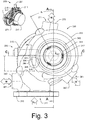
- Fig. 3 shows a lower plan view of an example a turbine housing 300 formed in part via the assembly 200 of Fig. 2 .
- the turbine housing 300 includes a flange portion 310 that includes an exhaust inlet 311, a bore 315 for a wastegate shaft, a volute wall 320, a base 340 (e.g., a center housing flange portion) that includes an opening 341 for receipt of a turbine wheel, features 342 disposed inwardly from a throat of a volute (e.g., for dimensional control for machining of the turbine housing), a turbine wheel shroud wall 344, coolant openings 361, 371 and 381 defined respectively by bosses 360, 370 and 380, and a wastegate opening 346 of a wastegate passage 347 (see, e.g., Fig. 5 ) where a wastegate seat 348 surrounds the wastegate opening 346.
- a wastegate seat 348 surrounds the wastegate opening 346.
- the coolant openings 361, 371 and 381 may be used for purposes of core stability (e.g., to help maintain core stability).
- the other two openings e.g., the openings 381 and 371
- the openings 381 and 371 may be used as an inlet and an outlet, for example, depending on packaging (e.g., engine bay characteristics, etc.), housing cooling strategy, etc.
- packaging e.g., engine bay characteristics, etc.
- housing cooling strategy e.g., one application may prefer to set the opening 381 as an inlet and to set the opening 371 as an outlet while another application may prefer to set the opening 371 as an inlet and to set the opening 381 as an outlet.
- a turbine housing that includes coolant passages may optionally be cooled to remove heat energy, which may act to reduce temperatures, reduce temperature gradients in time, reduce temperature gradients in space, etc., which may act to improve operation, longevity, etc. of a wastegate.
- thermal expansion of components may be more effectively managed (e.g., and one or more clearances), which may act to reduce risk of exhaust leakage about a shaft, a bushing, etc.
- risk of exhaust leakage about a wastegate shaft may be reduced via flowing coolant in a cooling passage of a turbine housing where the coolant passage may be a spiral that includes a winding that passes to one side of a wastegate shaft bore of the turbine housing and a winding that passes to another side of the wastegate shaft bore.
- the coolant passage may be a spiral that includes a winding that passes to one side of a wastegate shaft bore of the turbine housing and a winding that passes to another side of the wastegate shaft bore.
- a turbine housing may include wastegate features and a plurality of coolant passages that pass within the turbine housing where one or more of the coolant passages pass proximate to one or more of the wastegate features.
- one or more of the coolant passages may pass proximate to a wastegate shaft bore that may include a wastegate shaft optionally supported by a bushing.
- coolant may act to regulate the temperature of the wastegate shaft bore and hence the wastegate shaft and bushing, if present.
- a turbine housing may be cooled via coolant that flows in coolant passages to reduce heat radiation to an engine compartment.
- coolant may act as a heat recovery fluid, for example, for energy management.
- coolant may be heated by operation of a turbocharger where the heated coolant may act to improve engine cold start behavior.
- an improvement may be realized as to performance, including, for example, improvement in fuel consumption (e.g., efficiency).
- a turbine housing may be mounted in an engine compartment in an orientation with respect to gravity. Depending on the orientation, buoyancy may cause bubbles to flow in a particular direction.
- one or more coolant passages may be oriented in a direction that allows for flow of bubbles along the one or more coolant passages. For example, consider the passages having shapes formed by the members 265-1, 265-2 and 265-3 as being oriented axially with respect to gravity to promote flow of bubbles in the passages. In such an example, a bubble may flow from a spiral coolant passage to one of the axially directed passages. Such an arrangement may act as a bubble separator (e.g., to separate out air from coolant flowing in the spiral coolant passage).
- certain passages may be referred to as backbone passages that connect at least two windings of a spiral passage.
- a backbone passage may act to release trapped air bubbles (e.g., during charging of coolant, etc.).
- coolant may experience pressure, temperature, etc. that cause formation of bubbles (e.g., consider steam formation in coolant that includes water).
- one or more passages may act to separate such bubbles out of a spiral passage.
- backbone passages may be radially offset from a spiral passage, for example, to lessen risk of fluid channeling.
- a backbone passage may intersect with a spiral passage over a small portion of a wall of the spiral passage (see, e.g., the coolant core 207 of Fig. 2 ). In such a manner, flow in the spiral passage may be relatively uninterrupted in terms of its volumetric flow.
- a backbone passage may be in fluid communication with a plurality of windings of a spiral passage where pressure differences between connection points may result in some amount of flow in the backbone passage (e.g., from higher pressure windings to lower pressure windings).
- a backbone passage may include a cross-sectional flow area that is less than that of a spiral passage.
- resistance to flow in the backbone passage e.g., wall resistance
- cross-sectional area of inlets and outlets of passages can affect flow.
- an outlet of a spiral passage may be larger than a potential outlet of a backbone passage.
- a turbocharger turbine housing can include a base that defines a turbine wheel opening that includes an axis that defines an axial direction; an exhaust inlet flange that defines an exhaust inlet; an exhaust outlet flange that defines an exhaust outlet; a wastegate shaft bore, a wastegate passage, a wastegate opening for the wastegate passage and a wastegate seat disposed about the wastegate opening; bosses where each of the bosses defines a coolant opening; a spiral coolant passage in fluid communication with at least two of the coolant openings where the spiral coolant passage includes at least two windings with respect to an axial dimension of the turbocharger turbine housing; and at least one coolant passage that is in fluid communication with at least two of the at least two windings of the spiral coolant passage.
- Fig. 3 shows the plan view of the turbine housing 300 along with a line A-A and a line C-C.
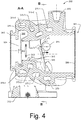
- a cross-sectional view of the turbine housing 300 along the line A-A is shown in Fig. 4 and a cross-sectional view of the turbine housing 300 along the line C-C is shown in Fig. 6 .
- the cross-sectional view of the turbine housing 300 shows various passages 375-1, 375-2, 375-3 and 375-4 that correspond to the spiral tubular portion 207 of the coolant passage core 204.
- Fig. 4 also shows a volute 322 defined in part by the volute wall 320 where the volute 322 includes a throat 324 that opens to a turbine wheel space 343 defined by the turbine housing 300.
- exhaust may flow via the exhaust inlet 311 of the flange portion 310 to the volute 322 and then to the turbine wheel space 343 via the throat 324.
- the exhaust may drive a turbine wheel disposed in the turbine wheel space 343 and then exit the turbine housing 300 via the exhaust outlet 351 of the outlet flange portion 350.
- a plug operatively coupled to the shaft may be positioned with respect to the wastegate opening 346, which includes the wastegate seat 348 thereabout.
- an arrow is shown in a general direction of wastegated exhaust flow via the wastegate opening 346.
- the cross-section along the line A-A is offset to the right of the wastegate opening 346, which may receive exhaust via the exhaust inlet 311 of the flange portion 310 and wastegate such exhaust without circulating it in the volute 320 and passing it through the throat 324 to the turbine wheel space 343.
- the coolant passages 375-1 and 375-2 are disposed proximate to the bore 315 and the coolant passages 375-3 and 375-4 are disposed proximate to the shroud wall 344 and the volute 322. Paths of the coolant passages 375-1, 375-2, 375-3 and 375-4 may be understood with reference to the windings 275-1, 275-2, 275-3 and 275-4 of the spiral tubular portion 207 of the coolant core 204 of the assembly 200 of Fig. 2 .
- Fig. 4 also shows a line B-B that passes through the coolant passage 375-1 and the bore 315.
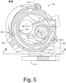
- Fig. 5 shows a corresponding cross-sectional view of the turbine housing 300 along the line B-B.
- coolant passages 365-1, 365-2 and 365-3 correspond to coolant passages that may be formed in part by the members 265-1, 265-2 and 265-3 of the coolant passage core 204 of the assembly 200 of Fig. 2 .
- the coolant passages 365-1, 365-2 and 365-3 may fluidly couple the passage 375-1 with other passages (e.g., 375-2, 375-3 and 375-4) in a "short circuit" manner.
- fluid may flow axially along one of the coolant passage 365-1, 365-2 or 365-3, for example, from one passage "winding" to another passage "winding".
- Such an approach may provide for reduction of deadspace, drainage, multiple flow paths, etc.
- Fig. 5 also shows a line D-D that is positioned between the flange portion 310 and a wall 377 that defines in part the passage 375-1.
- Fig. 7 shows a cross-sectional view of the turbine housing 300 along the line D-D.
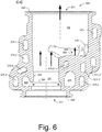
- Fig. 6 shows a cross-sectional view of the turbine housing 300 along the line C-C.
- Various arrows indicate some examples of possible directions of exhaust flow in the turbine housing 300.
- exhaust may flow from the volute 322 via the throat 324 (e.g., or nozzle) to the turbine wheel space 343 and then exit the turbine housing 300 via the exhaust outlet 351 of the outlet flange portion 350.
- a wastegate is in an open orientation
- exhaust may flow from the exhaust inlet 311 of the flange portion 310 to an exhaust outlet space 349 via the wastegate passage 347 and the wastegate opening 346 and to the exhaust outlet 351 of the outlet flange portion 350 of the turbine housing 300.
- a coolant passage labeled 375-5 exists, which is in fluid communication with other passages (e.g., as divided to surround a bypass channel).
- Fig. 8 shows an example of an assembly 800 that includes an actuator 801 with an actuator rod 802 that is operatively coupled to a link 803 that is operatively coupled to a peg 804 that is operatively coupled a control arm 398 fit to the wastegate shaft 392.
- an assembly may include various features of a turbocharger such as a GARRETT® GT 12 series turbocharger, a GARRETT® GT 14 series turbocharger, etc.
- the turbine housing 300 may be a turbine housing of a turbocharger that includes features of the GARRETT® GT 1446 turbocharger (e.g., compressor section, center housing section, wastegate controller, etc.).
- the wastegate assembly 390 includes the bushing 393 configured for receipt by the bore 315 of the turbine housing 300, a control arm 398 coupled to the peg 804 and a wastegate arm and plug (see, e.g., Fig. 3 ) that includes the shaft 392.
- the bushing 393 is disposed between the bore 315 and the shaft 392, for example, to support rotation of the shaft 392, to act to seal an exhaust chamber from an exterior space (e.g., to reduce exhaust leakage), etc.
- the bore 315, the bushing 393 and the shaft 392 may each be defined by a diameter or diameters as well as one or more lengths.
- the shaft 392 includes a diameter D s
- the bore 315 includes a diameter D B
- the bushing 393 includes an inner diameter D bi and an outer diameter D bo .
- a length of the shaft 392 exceeds a length of the bushing 393, which exceeds a length of the bore 315.
- Such lengths may be defined with respect to a shaft axis z s , a bushing axis z b and a bore axis z B .
- the bushing 393 is disposed axially between a shoulder of the shaft 392 (e.g., a face of the arm 398 where the arm 398 and the shaft 392 meet) and the control arm 398.
- a gap ⁇ z is shown between a surface of the bushing 398 and a surface of the control arm 398, which allows for axial movement of the shaft 392, for example, to facilitate self-centering of the plug 396 with respect to the wastegate seat 348 (see, e.g., Fig. 3 ).
- the plug 396 may include shape that acts to self-center with respect to a shape of the wastegate seat 348.
- the plug 396 may include a toroidal portion and the wastegate seat 348 may include a conical surface such that the plug 396 may self-center with respect to the wastegate seat 348. Self-centering may be facilitated by application of force that acts to maintain the plug 396 in a closed position with respect to the wastegate seat 348.
- the turbine housing 300 can include coolant passages that can be used to remove heat from the turbine housing 300 where at least one of the coolant passages passes proximate to the bore 315 for the wastegate shaft 392 (see, e.g., the passages 375-1 and 375-2 with respect to the bore 315 in Fig. 6 ).
- temperature may be controlled in a manner that facilitates operation of the wastegate shaft 392 via the actuator 801, that facilitates seating of the wastegate plug 396 with respect to the wastegate seat 348, that facilitates sealing of the bore 315 at least in part by the bushing 393, etc.
- temperature may be controlled to maintain clearances, contact surfaces, etc.
- temperature control may help to maintain a tilt clearance as indicated by the angle ⁇ and the contact points 399-1 and 399-2 in Fig. 8 and, for example, temperature control may help to maintain the clearance ⁇ z (e.g., to facilitate self-centering of a plug with respect to a wastegate seat).
- the turbine housing 300 may facilitate wastegate controllability and may reduce leakage of exhaust via the bore 315, which, in turn, may improve emissions.
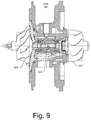
- Fig. 9 shows an example of a center housing rotating assembly (CHRA) 900 that includes a shaft 922, a compressor wheel 925, a turbine wheel 927, a center housing 928 and a bearing assembly 930 supported in a through bore of the center housing 928.
- a turbine housing such as the turbine housing 300 may be operatively coupled to the center housing 928 (e.g., as part of a turbocharger).
- a center housing may include lubricant passages for flow of lubricant at least to the bearing assembly 930, which rotatably supports the shaft 922, which may be joined to the turbine wheel 927 via welding (e.g., as a shaft and wheel assembly) and joined to the compressor wheel 925 via a bore of the compressor wheel 925 and a nut.
- a compressor wheel may be a boreless compressor wheel.
- an assembly may be fitted to an exhaust conduit or other component of an internal combustion engine (see, e.g., examples of Fig. 1 ), for example, via a flange such that exhaust is received via an inlet and directed to a volute of a turbine housing. From the volute, exhaust may be directed via a nozzle to a turbine wheel disposed in the turbine housing to flow and expand in a turbine wheel space. Exhaust can then exit the turbine wheel space by flowing to a chamber and then out of the turbine housing via an exhaust outlet opening.
- a wastegate arm and plug may be rotated such that at least a portion of the received exhaust can flow in a wastegate passage, past a wastegate seat and into the chamber, rather than through the nozzle to the turbine wheel space.
- the wastegated portion of the exhaust may then exit the turbine housing via the exhaust outlet opening (e.g., and pass to an exhaust system of a vehicle, be recirculated in part, etc.).
- a turbocharger assembly may include features of the assembly 800 of Fig. 8 , features of the turbine housing 300 of Fig. 3 (e.g., including wastegate features and coolant passages) and features of the CHRA of Fig. 9 .
- a turbocharger assembly may be fit with one or more conduits that can provide fluid to the coolant passages of the turbine housing 300 and one or more conduits that can receive fluid from the coolant passages of the turbine housing 300.
- Such fluid may be fluid of an engine cooling system of an internal combustion engine.
- a fluid may be at a temperature that is higher than that of a turbine housing.
- a block heater may be employed that may heat coolant to a temperature that is above an ambient temperature.
- circulation of such coolant to coolant passages of a turbine housing may act to increase the temperature of the turbine housing.
- a turbocharger turbine housing can include a base that defines a turbine wheel opening that includes an axis that defines an axial direction; a exhaust inlet flange that defines an exhaust inlet; an exhaust outlet flange that defines an exhaust outlet; a wastegate shaft bore, a wastegate passage, a wastegate opening for the wastegate passage and a wastegate seat disposed about the wastegate opening; bosses where each of the bosses defines a coolant opening; a spiral coolant passage in fluid communication with at least two of the coolant openings where the spiral coolant passage includes at least two windings with respect to an axial dimension of the turbocharger turbine housing; and at least one coolant passage that is in fluid communication with at least two of the at least two windings of the spiral coolant passage.
- the at least one coolant passage that is in fluid communication with at least two of the at least two windings of the spiral coolant passage can include a coolant passage that is radially offset from the axis and that extends a length in the axial direction.
- a turbocharger turbine housing can include a wastegate shaft bore that is at least partially disposed between two windings of a spiral coolant passage.
- one of the two windings may be a closest winding to the exhaust outlet.
- a turbocharger turbine housing can include three bosses where each of the bosses defines a respective coolant opening.
- one of the three coolant openings may be sealed (e.g., a sealed opening) and the other two of the coolant openings may be a coolant inlet and a coolant outlet.
- a coolant passage core for forming coolant passages in a turbocharger turbine housing can include a spiral tubular portion that extends from a first end to a second end and that includes at least two windings therebetween; and at least one member that joins at least two of the at least two windings of the spiral tubular portion.
- the core may include sand (e.g., compacted sand).
- a core may include a spiral tubular portion that includes at least three windings.
- a core may include a gap that exists between an end winding and an adjacent winding where the gap allows for formation of a wastegate shaft bore therebetween (e.g., via a portion of another core).
- a core can include at least two members that join at least two of at least two windings of a spiral tubular portion of the core.
- a coolant passage core can include a branch that extends from a spiral tubular portion where the branch includes an end.
- coolant passage core can include a first end, a second end and an end of the branch that are coolant opening features for formation of at least one coolant inlet and at least one coolant outlet.
- a method of cooling a turbocharger turbine housing can include flowing coolant to a spiral coolant passage that includes at least two windings; and flowing at least a portion of the coolant in an axial direction from one of the at least two windings to another one of the at least two windings via a coolant passage that is in fluid communication with at least two of the at least two windings of the spiral coolant passage.
- Such a method may include, for example, flowing air in an axial direction in the coolant passage.
- a method may include sealing one of three openings of a spiral coolant passage and using the two unsealed openings as a coolant inlet and a coolant outlet.
- a method can include flowing coolant to a spiral coolant passage and flowing at least a portion of the coolant in two of at least two windings of the spiral coolant passage where a wastegate shaft bore is at least partially disposed between the two windings.
- a method for forming a turbocharger turbine housing can include providing a coolant passage core that includes a spiral tubular portion that extends from a first end to a second end and that includes at least two windings therebetween and at least one member that joins at least two of the at least two windings of the spiral tubular portion; providing a central core disposed at least in part within a central space defined at least in part by the spiral tubular portion; pouring molten material into a mold that includes the coolant passage core and the central core; and removing the coolant passage core and the central core to form the turbocharger turbine housing.
Landscapes
- Engineering & Computer Science (AREA)
- Mechanical Engineering (AREA)
- General Engineering & Computer Science (AREA)
- Chemical & Material Sciences (AREA)
- Combustion & Propulsion (AREA)
- Chemical Kinetics & Catalysis (AREA)
- General Chemical & Material Sciences (AREA)
- Supercharger (AREA)
Claims (16)
- Turbochargerturbinengehäuse (300), das Folgendes umfasst:eine Grundeinheit (340), die eine Turbinenradöffnung bildet, die eine Achse umfasst, welche eine Axialrichtung bildet;einen Abgaseinlassflansch (310), der einen Abgaseinlass bildet;einen Abgasauslassflansch (350), der einen Abgasauslass bildet;eine Wastegate-Wellenbohrung (315), einen Wastegate-Durchgang (347), eine Wastegate-Öffnung (346) für den Wastegate-Durchgang und einen Wastegate-Sitz (348), der um die Wastegate-Öffnung (346) herum angeordnet ist;Anschlussstutzen (360, 370, 380), wobei jeder der Anschlussstutzen eine Kühlmittelöffnung (361, 371, 381) bildet;einen spiralförmigen Kühlmitteldurchgang (375-1, 375-2, 375-3, 375-4), der in Fluidaustausch mit mindestens zwei der Kühlmittelöffnungen (361, 371, 381) steht, wobei der spiralförmige Kühlmitteldurchgang mindestens zwei Krümmungen in Bezug auf eine Axialabmessung des Turbochargerturbinengehäuses aufweist; undmindestens einen Kühlmitteldurchgang (365-1, 365-2, 365-3), der in Fluidaustausch mit mindestens zwei der mindestens zwei Krümmungen des spiralförmigen Kühlmitteldurchgangs (375-1, 375-2, 375-3, 375-4) steht.
- Turbochargerturbinengehäuse nach Anspruch 1, wobei der mindestens eine Kühlmitteldurchgang, der in Fluidaustausch mit mindestens zwei der mindestens zwei Krümmungen des spiralförmigen Kühlmitteldurchgangs steht, einen Kühlmitteldurchgang umfasst, der radial von der Achse versetzt ist und der Länge nach in Axialrichtung verläuft.
- Turbochargerturbinengehäuse nach Anspruch 1, wobei der mindestens eine Kühlmitteldurchgang, der in Fluidaustausch mit mindestens zwei der mindestens zwei Krümmungen des spiralförmigen Kühlmitteldurchgangs steht, einen Kühlmitteldurchgang umfasst, der in Fluidaustausch mit mindestens drei Krümmungen des spiralförmigen Kühlmitteldurchgangs steht.
- Turbochargerturbinengehäuse nach Anspruch 1, wobei der spiralförmige Kühlmitteldurchgang mindestens drei Krümmungen umfasst.
- Turbochargerturbinengehäuse nach Anspruch 1, wobei der spiralförmige Kühlmitteldurchgang vier Krümmungen umfasst.
- Turbochargerturbinengehäuse nach Anspruch 1, wobei die Wastegate-Wellenbohrung zumindest teilweise zwischen zwei der Krümmungen des spiralförmigen Kühlmitteldurchgangs angeordnet ist.
- Turbochargerturbinengehäuse nach Anspruch 6, wobei eine der zwei Krümmungen eine am nächsten am Abgasauslass gelegene Krümmung ist.
- Turbochargerturbinengehäuse nach Anspruch 1, das drei Anschlussstutzen umfasst, wobei jeder der Anschlussstutzen eine jeweilige Kühlmittelöffnung bildet.
- Turbochargerturbinengehäuse nach Anspruch 8, wobei eine der drei Kühlmittelöffnungen abgedichtet ist und die anderen zwei Kühlmittelöffnungen einen Kühlmitteleinlass und einen Kühlmittelauslass umfassen.
- Kühlmitteldurchgangskern (204) zum Bilden von Kühlmitteldurchgängen in einem Turbochargerturbinengehäuse, wobei der Kühlmitteldurchgangskern Folgendes umfasst:einen spiralförmigen röhrenförmigen Abschnitt (207), der von einem ersten Ende zu einem zweiten Ende verläuft und der mindestens zwei Krümmungen dazwischen aufweist; undmindestens ein Element (265-1, 265-2, 265-3), das mindestens zwei der mindestens zwei Krümmungen des spiralförmigen röhrenförmigen Abschnitts miteinander verbindet.
- Kühlmitteldurchgangskern nach Anspruch 10, der Sand umfasst.
- Kühlmitteldurchgangskern nach Anspruch 10, wobei der spiralförmige röhrenförmige Abschnitt mindestens drei Krümmungen umfasst.
- Kühlmitteldurchgangskern nach Anspruch 10, wobei ein Spalt zwischen einer Endkrümmung und einer angrenzenden Krümmung zwecks Bildung einer Wastegate-Wellenbohrung dazwischen vorhanden ist.
- Kühlmitteldurchgangskern nach Anspruch 10, der mindestens zwei Elemente umfasst, die mindestes zwei der mindestens zwei Krümmungen des spiralförmigen röhrenförmigen Abschnitts miteinander verbinden.
- Kühlmitteldurchgangskern nach Anspruch 10, der eine Verzweigung umfasst, die sich von dem spiralförmigen röhrenförmigen Abschnitt erstreckt, wobei die Verzweigung ein Ende umfasst.
- Kühlmitteldurchgangskern nach Anspruch 15, wobei das erste Ende, das zweite Ende und das Ende der Verzweigung Kühlmittelöffnungsmerkmale zwecks Bildung mindestens eines Kühlmitteleinlasses und mindestens eines Kühlmittelauslasses umfassen.
Applications Claiming Priority (1)
| Application Number | Priority Date | Filing Date | Title |
|---|---|---|---|
| US14/318,990 US9702266B2 (en) | 2014-06-30 | 2014-06-30 | Turbocharger turbine housing |
Publications (2)
| Publication Number | Publication Date |
|---|---|
| EP2966271A1 EP2966271A1 (de) | 2016-01-13 |
| EP2966271B1 true EP2966271B1 (de) | 2017-03-29 |
Family
ID=53385510
Family Applications (1)
| Application Number | Title | Priority Date | Filing Date |
|---|---|---|---|
| EP15170747.8A Active EP2966271B1 (de) | 2014-06-30 | 2015-06-04 | Turbinengehäuse eines turboladers |
Country Status (3)
| Country | Link |
|---|---|
| US (1) | US9702266B2 (de) |
| EP (1) | EP2966271B1 (de) |
| CN (1) | CN105317480B (de) |
Families Citing this family (19)
| Publication number | Priority date | Publication date | Assignee | Title |
|---|---|---|---|---|
| CN105531459B (zh) * | 2013-12-04 | 2019-04-02 | 三菱重工业株式会社 | 板金涡轮壳体 |
| JP6103253B2 (ja) * | 2014-07-07 | 2017-03-29 | トヨタ自動車株式会社 | ターボチャージャ |
| US20160177806A1 (en) * | 2014-12-23 | 2016-06-23 | Caterpillar Inc. | Exhaust Outlet Elbow Center Divider Connection |
| JP6428670B2 (ja) * | 2016-02-16 | 2018-11-28 | マツダ株式会社 | エンジンの過給装置 |
| JP6315020B2 (ja) * | 2016-04-05 | 2018-04-25 | トヨタ自動車株式会社 | 内燃機関 |
| JP6747759B2 (ja) * | 2016-09-30 | 2020-08-26 | ダイハツ工業株式会社 | 排気ターボ過給機 |
| US20180355887A1 (en) * | 2016-12-09 | 2018-12-13 | Frontline Aerospace, Inc. | Centrifugal compressor cooling |
| US10544703B2 (en) | 2017-01-30 | 2020-01-28 | Garrett Transportation I Inc. | Sheet metal turbine housing with cast core |
| JP6882038B2 (ja) * | 2017-03-31 | 2021-06-02 | ダイハツ工業株式会社 | 排気ターボ過給機 |
| US10590944B2 (en) | 2017-10-05 | 2020-03-17 | Ford Global Technologies, Llc | Cooling system for compressor and method for operation thereof |
| US11339715B2 (en) * | 2018-09-28 | 2022-05-24 | Fb Design S.R.L. | Turbocharger assembly |
| CN109653862B (zh) * | 2018-12-12 | 2020-06-23 | 中国北方发动机研究所(天津) | 一种增压器风冷滑油热交换器 |
| US11821441B2 (en) * | 2019-07-23 | 2023-11-21 | Transportation Ip Holdings, Llc | System for a combined turbine and bearing case for a turbocharger |
| US11732729B2 (en) | 2021-01-26 | 2023-08-22 | Garrett Transportation I Inc | Sheet metal turbine housing |
| EP4134525A1 (de) * | 2021-08-11 | 2023-02-15 | Rolls-Royce plc | Rohrzusammenbau für gasturbinenmotor |
| US12060804B2 (en) * | 2021-09-26 | 2024-08-13 | Garret Transportation I Inc. | Turbocharger turbine housing |
| JP7537408B2 (ja) * | 2021-10-29 | 2024-08-21 | トヨタ自動車株式会社 | エンジン制御装置 |
| US12116902B2 (en) * | 2022-03-11 | 2024-10-15 | Garrett Transportation I Inc. | Twin scroll turbine housing |
| DE102024121817A1 (de) * | 2024-07-31 | 2026-02-05 | Borgwarner Inc. | Turboladergehäuse und Turbolader |
Family Cites Families (36)
| Publication number | Priority date | Publication date | Assignee | Title |
|---|---|---|---|---|
| US2273138A (en) | 1939-01-24 | 1942-02-17 | Risdon Mfg Co | Lipstick holder |
| US2900168A (en) * | 1955-03-24 | 1959-08-18 | Meredith M Nyborg | Reaction motor with liquid cooling means |
| US3811741A (en) | 1972-12-26 | 1974-05-21 | Garrett Corp | Bearing |
| US4068612A (en) | 1976-01-26 | 1978-01-17 | M & W Gear Company | Turbocharger housing construction for marine turbocharger and device for turbocharging a marine engine |
| IT1137783B (it) * | 1981-08-03 | 1986-09-10 | Nuovo Pignone Spa | Scabiatore di calore integrato con la cassa statorica di una turbina a gas |
| US4463564A (en) | 1981-10-23 | 1984-08-07 | The Garrett Corporation | Turbocharger turbine housing assembly |
| US4655043A (en) | 1983-05-26 | 1987-04-07 | The Garrett Corporation | Turbocharger |
| US5020319A (en) | 1987-06-09 | 1991-06-04 | Ngk Spark Plug Co., Ltd. | Hollow heat-resisting body assembly for internal combustion engine |
| CA1333196C (en) | 1987-12-28 | 1994-11-22 | Yasuyuki Aihara | Engine compartment cooling control system |
| DE3830761A1 (de) * | 1988-09-09 | 1990-03-15 | Mtu Muenchen Gmbh | Vorrichtung zur abgasreinigung von dieselmotoren |
| US4969805A (en) | 1989-05-02 | 1990-11-13 | Allied-Signal Inc. | Unidirectional turbocharger assembly |
| ES2081094T3 (es) | 1991-01-29 | 1996-02-16 | Brian Wade | Separadores de particulas y de fluidos ligeros y pesados. |
| JP3489332B2 (ja) | 1996-05-22 | 2004-01-19 | 日産自動車株式会社 | ターボチャージャのセンタハウジング |
| DE19640654A1 (de) | 1996-10-02 | 1998-04-09 | Asea Brown Boveri | Berstschutzvorrichtung für Radialturbinen von Turboladern |
| US6035637A (en) | 1997-07-01 | 2000-03-14 | Sunpower, Inc. | Free-piston internal combustion engine |
| KR100669487B1 (ko) | 2000-07-19 | 2007-01-16 | 허니웰 인터내셔날 인코포레이티드 | 가변 형상 터보차져 |
| CA2349508C (en) | 2001-06-04 | 2004-06-29 | Global Tech Environmental Products Inc. | Electrolysis cell and internal combustion engine kit comprising the same |
| JP2003035153A (ja) | 2001-07-23 | 2003-02-07 | Fuji Heavy Ind Ltd | ターボチャージャのコンプレッサハウジング構造 |
| EP1445448B1 (de) | 2002-12-12 | 2010-02-24 | Renault s.a.s. | Aufladegebläse-Anordnung für Brennkraftmaschine |
| US7108488B2 (en) | 2004-03-26 | 2006-09-19 | Honeywell International, Inc. | Turbocharger with hydrodynamic foil bearings |
| US7988426B2 (en) * | 2005-01-10 | 2011-08-02 | Honeywell International Inc. | Compressor ported shroud for foil bearing cooling |
| CN101415920A (zh) * | 2006-03-28 | 2009-04-22 | 株式会社捷太格特 | 增压器 |
| JP4797920B2 (ja) * | 2006-03-28 | 2011-10-19 | 株式会社ジェイテクト | 過給機 |
| WO2009102546A1 (en) | 2008-02-12 | 2009-08-20 | Honeywell International Inc. | Process for calibrating a variable-nozzle assembly of a turbochanger and a variable-nozzle assembly facilitating such process |
| DE102008011258A1 (de) | 2008-02-27 | 2009-09-10 | Continental Automotive Gmbh | Gekühltes Gehäuse bestehend aus einem Turbinengehäuse und einem Lagergehäuse eines Turboladers |
| US20100175377A1 (en) | 2009-01-12 | 2010-07-15 | Will Hippen | Cooling an electrically controlled turbocharger |
| DE112010004180T5 (de) * | 2009-10-30 | 2012-09-27 | Borgwarner Inc. | Turbinengehäuse eines Abgasturboladers |
| DE102010038909A1 (de) * | 2010-08-04 | 2012-02-09 | Bayerische Motoren Werke Aktiengesellschaft | Turbinengehäuse für einen Abgasturbolader |
| US8794921B2 (en) * | 2010-09-30 | 2014-08-05 | General Electric Company | Apparatus and methods for cooling platform regions of turbine rotor blades |
| DE102010064233A1 (de) | 2010-12-28 | 2012-06-28 | Continental Automotive Gmbh | Abgasturbolader mit wassergekühltem Turbinengehäuse mit integriertem elektrischen Wastegate-Steller |
| DE102011003907A1 (de) * | 2011-02-10 | 2012-08-16 | Continental Automotive Gmbh | Abgasturbolader mit gekühltem Turbinengehäuse |
| WO2012125385A2 (en) | 2011-03-14 | 2012-09-20 | Borgwarner Inc. | Turbine housing of an exhaust turbocharger |
| US9011086B2 (en) * | 2011-12-07 | 2015-04-21 | Honeywell International Inc. | Treated valve seat |
| WO2014062372A1 (en) * | 2012-10-15 | 2014-04-24 | Borgwarner Inc. | Exhaust-gas turbocharger |
| DE202013007472U1 (de) * | 2013-08-20 | 2013-09-26 | Borgwarner Inc. | Abgasturbolader |
| KR20150034848A (ko) * | 2013-09-25 | 2015-04-06 | 현대자동차주식회사 | 냉각구조를 갖는 터보차저 |
-
2014
- 2014-06-30 US US14/318,990 patent/US9702266B2/en active Active
-
2015
- 2015-06-04 EP EP15170747.8A patent/EP2966271B1/de active Active
- 2015-06-29 CN CN201510365250.XA patent/CN105317480B/zh active Active
Non-Patent Citations (1)
| Title |
|---|
| None * |
Also Published As
| Publication number | Publication date |
|---|---|
| US9702266B2 (en) | 2017-07-11 |
| EP2966271A1 (de) | 2016-01-13 |
| CN105317480A (zh) | 2016-02-10 |
| CN105317480B (zh) | 2018-12-14 |
| US20150377064A1 (en) | 2015-12-31 |
Similar Documents
| Publication | Publication Date | Title |
|---|---|---|
| US9702266B2 (en) | Turbocharger turbine housing | |
| US8984880B2 (en) | Turbine wastegate | |
| US9200532B2 (en) | Turbine wastegate | |
| EP2700823B1 (de) | Kompressorgehäuseanordnung | |
| KR102075661B1 (ko) | 터빈 웨이스트게이트 | |
| US9010109B2 (en) | Turbine wastegate | |
| KR20120099618A (ko) | 다단 터보차저 장치 | |
| US9163556B2 (en) | Turbine wastegate | |
| KR102594426B1 (ko) | 기체 유동 경로 및 액체 유동 경로를 갖는 터보차저 | |
| EP2915976B1 (de) | Bypassventilmechanismus einer Turboladerturbine | |
| US9890699B2 (en) | Turbocharger turbine wastegate mechanism | |
| CN107636279B (zh) | 多级式废气涡轮增压器和内燃机 | |
| US10526954B2 (en) | Turbocharger assembly | |
| US11821357B2 (en) | Turbocharger turbine assembly | |
| CN110080830A (zh) | 一种自带背盘冲击冷却的径流式增压装置 | |
| JP6384512B2 (ja) | ターボ過給機付きエンジンを搭載した車両 | |
| CN116357408B (zh) | 双涡管涡轮壳体 | |
| US12071888B2 (en) | Turbine housing and manifold assembly with control valve | |
| US20070193268A1 (en) | Turbocharger with liquid-cooled center housing | |
| CN119914398A (zh) | 一种具有集成式排气歧管的柴油机 | |
| RU150652U1 (ru) | Двигатель внутреннего сгорания | |
| EP3417159A1 (de) | Bypassventilmechanismus und verfahren zur herstellung und verwendung davon |
Legal Events
| Date | Code | Title | Description |
|---|---|---|---|
| PUAI | Public reference made under article 153(3) epc to a published international application that has entered the european phase |
Free format text: ORIGINAL CODE: 0009012 |
|
| 17P | Request for examination filed |
Effective date: 20150604 |
|
| AK | Designated contracting states |
Kind code of ref document: A1 Designated state(s): AL AT BE BG CH CY CZ DE DK EE ES FI FR GB GR HR HU IE IS IT LI LT LU LV MC MK MT NL NO PL PT RO RS SE SI SK SM TR |
|
| AX | Request for extension of the european patent |
Extension state: BA ME |
|
| GRAP | Despatch of communication of intention to grant a patent |
Free format text: ORIGINAL CODE: EPIDOSNIGR1 |
|
| GRAJ | Information related to disapproval of communication of intention to grant by the applicant or resumption of examination proceedings by the epo deleted |
Free format text: ORIGINAL CODE: EPIDOSDIGR1 |
|
| INTG | Intention to grant announced |
Effective date: 20160616 |
|
| INTC | Intention to grant announced (deleted) | ||
| GRAP | Despatch of communication of intention to grant a patent |
Free format text: ORIGINAL CODE: EPIDOSNIGR1 |
|
| INTG | Intention to grant announced |
Effective date: 20161118 |
|
| GRAS | Grant fee paid |
Free format text: ORIGINAL CODE: EPIDOSNIGR3 |
|
| GRAA | (expected) grant |
Free format text: ORIGINAL CODE: 0009210 |
|
| AK | Designated contracting states |
Kind code of ref document: B1 Designated state(s): AL AT BE BG CH CY CZ DE DK EE ES FI FR GB GR HR HU IE IS IT LI LT LU LV MC MK MT NL NO PL PT RO RS SE SI SK SM TR |
|
| REG | Reference to a national code |
Ref country code: GB Ref legal event code: FG4D |
|
| REG | Reference to a national code |
Ref country code: CH Ref legal event code: EP |
|
| REG | Reference to a national code |
Ref country code: AT Ref legal event code: REF Ref document number: 879975 Country of ref document: AT Kind code of ref document: T Effective date: 20170415 |
|
| REG | Reference to a national code |
Ref country code: FR Ref legal event code: PLFP Year of fee payment: 3 |
|
| REG | Reference to a national code |
Ref country code: IE Ref legal event code: FG4D |
|
| REG | Reference to a national code |
Ref country code: DE Ref legal event code: R096 Ref document number: 602015001980 Country of ref document: DE |
|
| PG25 | Lapsed in a contracting state [announced via postgrant information from national office to epo] |
Ref country code: GR Free format text: LAPSE BECAUSE OF FAILURE TO SUBMIT A TRANSLATION OF THE DESCRIPTION OR TO PAY THE FEE WITHIN THE PRESCRIBED TIME-LIMIT Effective date: 20170630 Ref country code: NO Free format text: LAPSE BECAUSE OF FAILURE TO SUBMIT A TRANSLATION OF THE DESCRIPTION OR TO PAY THE FEE WITHIN THE PRESCRIBED TIME-LIMIT Effective date: 20170629 Ref country code: LT Free format text: LAPSE BECAUSE OF FAILURE TO SUBMIT A TRANSLATION OF THE DESCRIPTION OR TO PAY THE FEE WITHIN THE PRESCRIBED TIME-LIMIT Effective date: 20170329 Ref country code: FI Free format text: LAPSE BECAUSE OF FAILURE TO SUBMIT A TRANSLATION OF THE DESCRIPTION OR TO PAY THE FEE WITHIN THE PRESCRIBED TIME-LIMIT Effective date: 20170329 Ref country code: HR Free format text: LAPSE BECAUSE OF FAILURE TO SUBMIT A TRANSLATION OF THE DESCRIPTION OR TO PAY THE FEE WITHIN THE PRESCRIBED TIME-LIMIT Effective date: 20170329 |
|
| REG | Reference to a national code |
Ref country code: NL Ref legal event code: MP Effective date: 20170329 |
|
| REG | Reference to a national code |
Ref country code: AT Ref legal event code: MK05 Ref document number: 879975 Country of ref document: AT Kind code of ref document: T Effective date: 20170329 |
|
| PG25 | Lapsed in a contracting state [announced via postgrant information from national office to epo] |
Ref country code: BG Free format text: LAPSE BECAUSE OF FAILURE TO SUBMIT A TRANSLATION OF THE DESCRIPTION OR TO PAY THE FEE WITHIN THE PRESCRIBED TIME-LIMIT Effective date: 20170629 Ref country code: RS Free format text: LAPSE BECAUSE OF FAILURE TO SUBMIT A TRANSLATION OF THE DESCRIPTION OR TO PAY THE FEE WITHIN THE PRESCRIBED TIME-LIMIT Effective date: 20170329 Ref country code: SE Free format text: LAPSE BECAUSE OF FAILURE TO SUBMIT A TRANSLATION OF THE DESCRIPTION OR TO PAY THE FEE WITHIN THE PRESCRIBED TIME-LIMIT Effective date: 20170329 Ref country code: LV Free format text: LAPSE BECAUSE OF FAILURE TO SUBMIT A TRANSLATION OF THE DESCRIPTION OR TO PAY THE FEE WITHIN THE PRESCRIBED TIME-LIMIT Effective date: 20170329 |
|
| PG25 | Lapsed in a contracting state [announced via postgrant information from national office to epo] |
Ref country code: NL Free format text: LAPSE BECAUSE OF FAILURE TO SUBMIT A TRANSLATION OF THE DESCRIPTION OR TO PAY THE FEE WITHIN THE PRESCRIBED TIME-LIMIT Effective date: 20170329 |
|
| PG25 | Lapsed in a contracting state [announced via postgrant information from national office to epo] |
Ref country code: AT Free format text: LAPSE BECAUSE OF FAILURE TO SUBMIT A TRANSLATION OF THE DESCRIPTION OR TO PAY THE FEE WITHIN THE PRESCRIBED TIME-LIMIT Effective date: 20170329 Ref country code: RO Free format text: LAPSE BECAUSE OF FAILURE TO SUBMIT A TRANSLATION OF THE DESCRIPTION OR TO PAY THE FEE WITHIN THE PRESCRIBED TIME-LIMIT Effective date: 20170329 Ref country code: SK Free format text: LAPSE BECAUSE OF FAILURE TO SUBMIT A TRANSLATION OF THE DESCRIPTION OR TO PAY THE FEE WITHIN THE PRESCRIBED TIME-LIMIT Effective date: 20170329 Ref country code: EE Free format text: LAPSE BECAUSE OF FAILURE TO SUBMIT A TRANSLATION OF THE DESCRIPTION OR TO PAY THE FEE WITHIN THE PRESCRIBED TIME-LIMIT Effective date: 20170329 Ref country code: ES Free format text: LAPSE BECAUSE OF FAILURE TO SUBMIT A TRANSLATION OF THE DESCRIPTION OR TO PAY THE FEE WITHIN THE PRESCRIBED TIME-LIMIT Effective date: 20170329 Ref country code: CZ Free format text: LAPSE BECAUSE OF FAILURE TO SUBMIT A TRANSLATION OF THE DESCRIPTION OR TO PAY THE FEE WITHIN THE PRESCRIBED TIME-LIMIT Effective date: 20170329 Ref country code: IT Free format text: LAPSE BECAUSE OF FAILURE TO SUBMIT A TRANSLATION OF THE DESCRIPTION OR TO PAY THE FEE WITHIN THE PRESCRIBED TIME-LIMIT Effective date: 20170329 |
|
| PG25 | Lapsed in a contracting state [announced via postgrant information from national office to epo] |
Ref country code: PL Free format text: LAPSE BECAUSE OF FAILURE TO SUBMIT A TRANSLATION OF THE DESCRIPTION OR TO PAY THE FEE WITHIN THE PRESCRIBED TIME-LIMIT Effective date: 20170329 Ref country code: SM Free format text: LAPSE BECAUSE OF FAILURE TO SUBMIT A TRANSLATION OF THE DESCRIPTION OR TO PAY THE FEE WITHIN THE PRESCRIBED TIME-LIMIT Effective date: 20170329 Ref country code: IS Free format text: LAPSE BECAUSE OF FAILURE TO SUBMIT A TRANSLATION OF THE DESCRIPTION OR TO PAY THE FEE WITHIN THE PRESCRIBED TIME-LIMIT Effective date: 20170729 |
|
| REG | Reference to a national code |
Ref country code: DE Ref legal event code: R097 Ref document number: 602015001980 Country of ref document: DE |
|
| PG25 | Lapsed in a contracting state [announced via postgrant information from national office to epo] |
Ref country code: MC Free format text: LAPSE BECAUSE OF FAILURE TO SUBMIT A TRANSLATION OF THE DESCRIPTION OR TO PAY THE FEE WITHIN THE PRESCRIBED TIME-LIMIT Effective date: 20170329 Ref country code: DK Free format text: LAPSE BECAUSE OF FAILURE TO SUBMIT A TRANSLATION OF THE DESCRIPTION OR TO PAY THE FEE WITHIN THE PRESCRIBED TIME-LIMIT Effective date: 20170329 |
|
| PLBE | No opposition filed within time limit |
Free format text: ORIGINAL CODE: 0009261 |
|
| STAA | Information on the status of an ep patent application or granted ep patent |
Free format text: STATUS: NO OPPOSITION FILED WITHIN TIME LIMIT |
|
| 26N | No opposition filed |
Effective date: 20180103 |
|
| REG | Reference to a national code |
Ref country code: IE Ref legal event code: MM4A |
|
| PG25 | Lapsed in a contracting state [announced via postgrant information from national office to epo] |
Ref country code: LU Free format text: LAPSE BECAUSE OF NON-PAYMENT OF DUE FEES Effective date: 20170604 Ref country code: IE Free format text: LAPSE BECAUSE OF NON-PAYMENT OF DUE FEES Effective date: 20170604 |
|
| REG | Reference to a national code |
Ref country code: BE Ref legal event code: MM Effective date: 20170630 |
|
| PG25 | Lapsed in a contracting state [announced via postgrant information from national office to epo] |
Ref country code: SI Free format text: LAPSE BECAUSE OF FAILURE TO SUBMIT A TRANSLATION OF THE DESCRIPTION OR TO PAY THE FEE WITHIN THE PRESCRIBED TIME-LIMIT Effective date: 20170329 |
|
| REG | Reference to a national code |
Ref country code: FR Ref legal event code: PLFP Year of fee payment: 4 |
|
| PG25 | Lapsed in a contracting state [announced via postgrant information from national office to epo] |
Ref country code: BE Free format text: LAPSE BECAUSE OF NON-PAYMENT OF DUE FEES Effective date: 20170630 |
|
| PG25 | Lapsed in a contracting state [announced via postgrant information from national office to epo] |
Ref country code: MT Free format text: LAPSE BECAUSE OF NON-PAYMENT OF DUE FEES Effective date: 20170604 |
|
| REG | Reference to a national code |
Ref country code: CH Ref legal event code: PL |
|
| PG25 | Lapsed in a contracting state [announced via postgrant information from national office to epo] |
Ref country code: CH Free format text: LAPSE BECAUSE OF NON-PAYMENT OF DUE FEES Effective date: 20180630 Ref country code: LI Free format text: LAPSE BECAUSE OF NON-PAYMENT OF DUE FEES Effective date: 20180630 |
|
| PG25 | Lapsed in a contracting state [announced via postgrant information from national office to epo] |
Ref country code: HU Free format text: LAPSE BECAUSE OF FAILURE TO SUBMIT A TRANSLATION OF THE DESCRIPTION OR TO PAY THE FEE WITHIN THE PRESCRIBED TIME-LIMIT; INVALID AB INITIO Effective date: 20150604 |
|
| REG | Reference to a national code |
Ref country code: DE Ref legal event code: R081 Ref document number: 602015001980 Country of ref document: DE Owner name: GARRETT TRANSPORTATION I INC., TORRANCE, US Free format text: FORMER OWNER: HONEYWELL INTERNATIONAL INC., MORRIS PLAINS, N.J., US |
|
| REG | Reference to a national code |
Ref country code: GB Ref legal event code: 732E Free format text: REGISTERED BETWEEN 20190725 AND 20190731 |
|
| PGFP | Annual fee paid to national office [announced via postgrant information from national office to epo] |
Ref country code: FR Payment date: 20190625 Year of fee payment: 5 |
|
| PG25 | Lapsed in a contracting state [announced via postgrant information from national office to epo] |
Ref country code: CY Free format text: LAPSE BECAUSE OF FAILURE TO SUBMIT A TRANSLATION OF THE DESCRIPTION OR TO PAY THE FEE WITHIN THE PRESCRIBED TIME-LIMIT Effective date: 20170329 |
|
| PG25 | Lapsed in a contracting state [announced via postgrant information from national office to epo] |
Ref country code: MK Free format text: LAPSE BECAUSE OF FAILURE TO SUBMIT A TRANSLATION OF THE DESCRIPTION OR TO PAY THE FEE WITHIN THE PRESCRIBED TIME-LIMIT Effective date: 20170329 |
|
| PG25 | Lapsed in a contracting state [announced via postgrant information from national office to epo] |
Ref country code: TR Free format text: LAPSE BECAUSE OF FAILURE TO SUBMIT A TRANSLATION OF THE DESCRIPTION OR TO PAY THE FEE WITHIN THE PRESCRIBED TIME-LIMIT Effective date: 20170329 |
|
| PG25 | Lapsed in a contracting state [announced via postgrant information from national office to epo] |
Ref country code: PT Free format text: LAPSE BECAUSE OF FAILURE TO SUBMIT A TRANSLATION OF THE DESCRIPTION OR TO PAY THE FEE WITHIN THE PRESCRIBED TIME-LIMIT Effective date: 20170329 |
|
| PG25 | Lapsed in a contracting state [announced via postgrant information from national office to epo] |
Ref country code: AL Free format text: LAPSE BECAUSE OF FAILURE TO SUBMIT A TRANSLATION OF THE DESCRIPTION OR TO PAY THE FEE WITHIN THE PRESCRIBED TIME-LIMIT Effective date: 20170329 |
|
| PG25 | Lapsed in a contracting state [announced via postgrant information from national office to epo] |
Ref country code: FR Free format text: LAPSE BECAUSE OF NON-PAYMENT OF DUE FEES Effective date: 20200630 |
|
| PGFP | Annual fee paid to national office [announced via postgrant information from national office to epo] |
Ref country code: DE Payment date: 20250626 Year of fee payment: 11 |
|
| PGFP | Annual fee paid to national office [announced via postgrant information from national office to epo] |
Ref country code: GB Payment date: 20250618 Year of fee payment: 11 |