EP2966006A1 - Non pre-pierced capsule for preparing a beverage - Google Patents
Non pre-pierced capsule for preparing a beverage Download PDFInfo
- Publication number
- EP2966006A1 EP2966006A1 EP15176075.8A EP15176075A EP2966006A1 EP 2966006 A1 EP2966006 A1 EP 2966006A1 EP 15176075 A EP15176075 A EP 15176075A EP 2966006 A1 EP2966006 A1 EP 2966006A1
- Authority
- EP
- European Patent Office
- Prior art keywords
- capsule
- ring
- outer ring
- capsule according
- plane
- Prior art date
- Legal status (The legal status is an assumption and is not a legal conclusion. Google has not performed a legal analysis and makes no representation as to the accuracy of the status listed.)
- Granted
Links
Images


Classifications
-
- B—PERFORMING OPERATIONS; TRANSPORTING
- B65—CONVEYING; PACKING; STORING; HANDLING THIN OR FILAMENTARY MATERIAL
- B65D—CONTAINERS FOR STORAGE OR TRANSPORT OF ARTICLES OR MATERIALS, e.g. BAGS, BARRELS, BOTTLES, BOXES, CANS, CARTONS, CRATES, DRUMS, JARS, TANKS, HOPPERS, FORWARDING CONTAINERS; ACCESSORIES, CLOSURES, OR FITTINGS THEREFOR; PACKAGING ELEMENTS; PACKAGES
- B65D85/00—Containers, packaging elements or packages, specially adapted for particular articles or materials
- B65D85/70—Containers, packaging elements or packages, specially adapted for particular articles or materials for materials not otherwise provided for
- B65D85/804—Disposable containers or packages with contents which are mixed, infused or dissolved in situ, i.e. without having been previously removed from the package
- B65D85/8043—Packages adapted to allow liquid to pass through the contents
Definitions
- the present invention relates to a capsule for receiving a substance for the preparation of a beverage when the capsule is installed in a machine type coffee machine or infusion to be held by a piston during the passage of the liquid extractor to through the capsule and the substance it contains after drilling the bottom by the piston pins distributed over a circle centered on the axis of the housing receives the capsule, the capsule having a bottom and a side wall generally forming a truncated cone and a rim covered by a lid after loading the substance into the capsule.
- Capsules having a frustoconical general shape and in particular a capsule described in the document are already known.
- FR 12 57 144 This pre-drilled capsule has a bottom provided with holes distributed over concentric circles and having a funnel shape open towards the outside and whose narrowed portion opens into the capsule.
- the holes distributed over the entire surface of the bottom are intended to distribute as regularly as possible hot water (or more generally the hot fluid) in the volume of the capsule. For the same reason, it is necessary to avoid that the pins of the piston do not pierce the bottom in more and do not disturb by holes larger than the calibrated holes, the regularity of the distribution of the water on all the surface of the bottom.
- the bottom has a circular rib projecting inwardly of the capsule to receive the pins of the piston without them touching the bottom.
- this capsule relatively complex shape requires a special packaging, hermetic, in the form of a pouch certainly facilitating handling but having the disadvantage of representing an additional cost.
- the present invention aims to develop a simple non-pre-pierced capsule, easy to package and use, and allowing accurate drilling of the bottom by the pins of the machine, without deformation of the bottom for an entry and distribution as regular as possible of the liquid or extraction fluid in the capsule and the substance it contains.
- the capsule which has the advantage of confining the coffee and its aromas in the narrow volume of the single capsule until the moment of drilling of the capsule and the arrival of the hot fluid allows, thanks to its precision of the holes of the bottom and the absence of deformation of the bottom, a very regular distribution of the fluid in the substance of the capsule for a regular extraction as in the case of a pre-drilled bottom capsule, while avoiding the outer shell and its disadvantages .
- the quality of the coffee thus prepared or more generally of the drink according to the substance packaged in the capsule is better for the same quantity of substance, although the arrival of the hot fluid in the capsule, is done by the only holes made by the pins of the piston.
- the rigid structure formed by the reinforced central disk, the outer ring and the radial ribs constitutes a strong frame with wall surfaces of reduced thickness, formed by sectors of the intermediate ring.
- This structure combines strength and rigidity, avoiding any distortion of the bottom and the capsule, detrimental to the smooth running of the preparation of the liquid without complicating the regular piercing of the bottom by the pins of the piston of the machine, achieving regular perforations essential to good preparation, to avoid any preferential passage of hot fluid through a only part of the mass of the substance.
- the internal ribs define areas that weaken the bottom locally facilitating its perforation by the pins of the piston of the machine whose peripheral distribution is similar in the different machines using such capsules.
- the perforations of the bottom made with the pins do not produce any deformation of the bottom since the pins can easily pass through the veil of the inner groove without the bottom being weakened since this veil extends only to areas of reduced width. Even if a pin meets a rib, it crosses without depressing the bottom perfectly stiffened by the extra thickness of the outer ring and the central portion of the bottom, especially since the capsule is held rigidly by the side wall through its junction with the base cone and the base cylinder.
- the side wall is connected to the base cone secured to the bottom by a lower cone of very small conicity.
- This low conicity facilitates the insertion of the capsule into the cavity of the machine and also under the same conditions, the extraction of the capsule once the treatment is done.
- the outer surface of the central disk is flat as well as the outer surface of the peripheral ring, the plane being perpendicular to the axis as the plane while being set back with respect to the latter, and the crown intermediate has a truncated cone face joining the central disc and the outer crown.
- This form of the structure and in particular the intermediate crown shaped truncated cone facilitates the regular penetration of the piston pins of the extraction machine and thus makes it possible to achieve very regular passages for the hot fluid so that it be distributed in a particularly regular manner inside the whole mass of the substance contained in the capsule.
- the outer junction between the intermediate ring and the outer ring forms a recess and the inner junction with the inner radial extension of the outer ring.
- This junction of the membrane of the intermediate ring with the outer ring promotes the holding of this junction, avoiding any tear initiation at the junction of the intermediate ring with the outer ring.
- the rib has an inner side edge in the plane perpendicular to the axis so that the rib joined by its top, the base cone.
- the ribs of the bottom thus make it possible to bear very firmly and rigidly against the base cone, which strengthens the backbone of the bottom and improves its rigidity.
- the bottom has a plurality of radial ribs dividing it into circular ring sectors, including four sectors.
- the radial ribs of the bottom are preferably, when they are even in number, in diametrically opposite positions.
- the junction cone above the cylindrical portion of the wall comprises, on its inner surface, interlocking brackets having a rising side and an upper side intersecting forming a support stop which forms with the upper side a peripheral support surface on which rests the stiffening cone of the nested empty capsule.
- the stop at the meeting of the base cone and the cylinder is set back relative to the extension of the geometric conical frustum of the conical wall.
- the interlocking brackets on the inner periphery of the cylindrical part form a particularly stable support receiving the stiffening cone so that the support between the cone and the brackets is practically limited to a point contact of this conical surface slightly inclined with respect to the background and so with respect to the bearing surface formed by the upper edges of the different consoles.
- the support brackets stiffen this area of the wall at the junction between the cylindrical portion and the conical portion.
- the inner surface of the cylindrical portion has a peripheral stiffening rib which reinforces the cylindrical portion against crushing by the pressurized liquid, at the moment of injection of the liquid into the capsule, exerted on the entire peripheral area and not only on the bottom.
- the bottom has an increased thickness relative to the thickness of the side wall.
- the bottom has a thickness of the order of 1 mm and the veil of the intermediate ring has a thickness of about 1/5 th of the thickness of the bottom.
- the underside of the rim receiving the edge of the piston of the machine comprises a stiffening ring and an outer ring defining with an inner ring near the side wall and in the meantime, a sealing lip forming the receiving surface of the piston edge.
- This receiving surface thus makes it possible to receive in a very tight manner, the edge of the piston so as to improve the passage of the fluid under pressure into the product contained in the capsule to prevent this liquid, that is to say the water does not bypass the junction between the piston and the capsule without passing through the product contained in the capsule.
- the outer ring, the inner ring and the lip have a triangular section with an angle at the summit of the order of 40 °.
- the base cone comprises near its junction with the bottom a lower rib, in particular of rectangular section. This rib stiffens interestingly the background.
- the subject of the invention is a non-pre-pierced capsule C for receiving a substance for preparing a beverage such as coffee or an infusion.
- this capsule C has a bottom 1 through which the hot fluid (hot water or mixture of hot water and steam) arrives for the preparation of the drink.
- the bottom 1 is connected to the side wall 3 by a conical base 2.
- the side wall 3 consists of a lower cone 31 of a very low taper joining a conical main wall 33 by a conical junction 32.
- the main wall 33 continues with a flange 4.
- peripheral ribs 34 serving as hooking ribs 34 for extracting the capsule from the injection mold. These ribs 34 do not intervene in the subsequent operation of the capsule, that is to say its filling with a substance powder (coffee, tea) or during the establishment and use of the capsule C in a machine for preparing the drink.
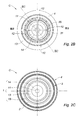
- FIGS. 2A , 2B, 2C show in more detail the different elements of the structure of the capsule C, symmetrical in rotation with respect to its axis (xx).
- the side view ( Fig. 2A ) shows in particular the shape of the bottom 1 having in its center (axis xx) a reentrant dome 11 of stiffening and various structural elements detailed later.
- the bottom 1 continues upwards through the base cone 2 which, with the bottom 1, an angle of the order of 30 to 45 °.
- the base cone 2 joins the lower cone 31 stiffening the capsule near the bottom.
- the lower cone 31 is connected via the conical junction 32 to the conical wall 33.
- the conical junction 32 has a greater conicity than the lower cone 31 and the conical wall 33 to absorb over a short height, the difference in diameter relative to the lower cone 31 which allows the interlocking of empty capsules while remaining, through its side wall 3, in a frustoconical envelope.
- the junction 32 of the lower cone 31 and the conical wall 33 is provided with interlocking brackets 35 whose rising side 351 extends the inner surface of the lower cone 31 and the upper side 352 forms a bearing surface of interlocking ( figure 3 ).
- the inner surface of the lower cone 31 is provided with a stiffening peripheral rib 311.
- the Figure 2B shows the internal structure of the capsule C and especially the lower part with the bottom 1.
- the top view of the Figure 2C shows the circular contours of the different annular surfaces of the bottom 1 corresponding to flat or conical crowns whose details will be described later.
- the top 41 of the flange 4 is flat to receive the cap 5 and the bottom is bordered by a stiffening ring 42.
- the underside Near the junction of the flange 4 and the wall 3, the underside has an outer ring 43 of triangular section and an inner ring 44 also of triangular section between which there is a sealing lip 45.
- This space between the outer ring 43 and the inner ring 44 receives the edge P schematically shown, the cylindrical chamber of the piston of the machine.
- the rim 4 of the capsule is thus guided to appropriately receive the peripheral edge of the piston which is positioned between the outer ring 43 and the inner ring 44 by crushing the sealing lip 45, the assembly forming a labyrinth seal.
- the outer ring 43 is truncated triangular section or trapezoidal with an angle at the summit of the order of 40 °.
- the inner ring 44 also has a triangular section with a rounded top with an angle of the order of 40 ° and the interval between the two rings 43, 44 is occupied by the sealing lip 45 which also has a triangular section with a sharp top with an angle of the order of 40 ° so that the sealing lip 45 relatively high, can be crushed with good contact against the edge P also pressed against the rings 43, 44.
- the figure 3 shows more explicitly the different components of the capsule C already described, in particular the meeting line 321 between the conical junction 32 and the conical wall 33 and the shape of the brackets 35 having a rising side 351 that is say parallel to the axis xx, in the extension of the inner wall of the lower cone 31 and the upper side 352 in a plane perpendicular to the axis xx; both sides form at their intersection a bearing stop 353.
- the upper side 352 of the brackets 35 also forms a peripheral bearing surface.
- the junction of the bottom 1 and the side wall 3 is reinforced by the very open shape of the base cone 2 whose wall has substantially the thickness of the side wall 3.
- FIG. 3 shows by a double view in axial section by a diametral plane IIIB containing on the one hand a radial rib 12 (in fact two ribs aligned diametrically) and on the other hand in dotted lines, by superposition, an axial section made by a plane IIIC does not not containing radial ribs 12.
- a diametral plane IIIB containing on the one hand a radial rib 12 (in fact two ribs aligned diametrically) and on the other hand in dotted lines, by superposition, an axial section made by a plane IIIC does not not containing radial ribs 12.
- the figures 3 , 3B show the lower cone 31 of very low conicity which gives it a form comparable to a cylinder. However the slight taper is highlighted by the angle ⁇ c, with respect to the direction xx. This taper facilitates the introduction of the capsule C in a machine or its extraction after treatment.
- the bottom 1 connected to the base cone 2 has a form of revolution, complex, both in the sector separating two ribs 12, and at the ribs 12.
- the section of the bottom 1 shows the peripheral ring 15, of thickness equal to or close to that of the parts 2, 3.
- the peripheral ring 15 continues towards the axis xx by an intermediate ring 13 divided into sectors by the radial ribs 12 and having a very small wall thickness relative to that of the wall of the peripheral ring 15 to be easily traversed by the pins of the machine.
- the intermediate ring 13 joins the central disk 14 of great thickness.
- the central disk 14 is situated outside in the plane P0 perpendicular to the axis xx while the outer ring 15 is located in a plane P1, also perpendicular to the axis xx, but above the plane P0, that is, ie recessed towards the inside of the capsule; the intermediate ring 13 thus has a frustoconical shape making the junction between the two planes P0, P1 with however an external recess 131 at the junction of the rings 13, 15 and internally an inner radial or reentrant extension 132 of the ring 15 to support the junction from the edge of the crown intermediate 13 against the thrust of the pins and the pressure of the hot fluid. This reinforcement prevents any initiation of tearing of the membrane at its junction with the outer ring 15.
- the inner surface of the peripheral ring 15 and that of the central disk 14, outside the dome 11, is in the same plane P2 perpendicular to the axis xx.
- the figures 3 , 3C show the structure of the radial rib 12 which, advantageously, is a double, that is to say diametrical, rib.
- the edge 121 matches the shape of the different parts of the bottom 1 and is not a relief so that the outer surface of the bottom 1 has a shape of surface of revolution of axis xx.
- the rib 12 has a straight edge 122 contained in a plane perpendicular to the axis xx; this side 122 exceeds the various inner reliefs of the bottom and joins the base cone 2 thus connecting the central disk 14 and the outer ring 15.
- the capsule C is stiffened and the bottom 1 resists the thrust of the piston pins and does not deform, avoiding crushing of the capsule, favoring its piercing by the pins of the piston and allowing a better compression of the substance, especially coffee, ie no loss of pressure and thus better extraction.
- the frame of the bottom 1 is rigid and protects the piercing areas, intentionally weakened, to prevent accidental breakage during handling in the machines for loading and sealing capsules, or during packaging operations or even when placing in place of the capsule in the chamber of the coffee machine.
- the bottom 1 facilitates the holding of the capsule C standing on its bottom 1 having a large plane surface 14 (plane PO).
- the capsule C as described is made very simply by injection or stamping a food grade plastic material. It is easily stacked after its manufacture and is simply unstacked for filling.
Abstract
Capsule (C) dont le fond (1) est formé par un disque central (14) et une couronne extérieure (15) reliée à la paroi latérale (3) par un cône de base (2). Une couronne intermédiaire (13) relie le disque central (14) et la couronne extérieure (15). Son épaisseur est réduite par rapport à celle des autres parties du fond. Des nervures radiales (12) relient le disque central (14) à la couronne extérieure (15) en étant solidaires également de la couronne intermédiaire (13).Capsule (C) whose bottom (1) is formed by a central disk (14) and an outer ring (15) connected to the side wall (3) by a base cone (2). An intermediate ring (13) connects the central disk (14) and the outer ring (15). Its thickness is reduced compared to that of the other parts of the bottom. Radial ribs (12) connect the central disk (14) to the outer ring (15) and are also integral with the intermediate ring (13).
Description
La présente invention se rapporte à une capsule destinée à recevoir une substance pour la préparation d'une boisson lorsque la capsule est installée dans une machine de type machine à café ou à infusion pour y être tenue par un piston pendant le passage du liquide extracteur à travers la capsule et la substance qu'elle contient après le perçage du fond par les picots du piston répartis sur un cercle centré sur l'axe du logement reçoit la capsule, la capsule ayant un fond et une paroi latérale s'inscrivant globalement dans un tronc de cône ainsi qu'un rebord couvert par un opercule après chargement de la substance dans la capsule.The present invention relates to a capsule for receiving a substance for the preparation of a beverage when the capsule is installed in a machine type coffee machine or infusion to be held by a piston during the passage of the liquid extractor to through the capsule and the substance it contains after drilling the bottom by the piston pins distributed over a circle centered on the axis of the housing receives the capsule, the capsule having a bottom and a side wall generally forming a truncated cone and a rim covered by a lid after loading the substance into the capsule.
On connaît déjà des capsules ayant une forme générale tronconique et notamment une capsule décrite dans le document
Les trous répartis sur toute la surface du fond ont pour but de distribuer aussi régulièrement que possible l'eau chaude (ou plus généralement le fluide chaud) dans le volume de la capsule. Pour cette même raison, il faut éviter que les picots du piston ne percent le fond en plus et ne perturbent par des trous plus grands que les trous calibrés, la régularité de la distribution de l'eau sur toute la surface du fond.The holes distributed over the entire surface of the bottom are intended to distribute as regularly as possible hot water (or more generally the hot fluid) in the volume of the capsule. For the same reason, it is necessary to avoid that the pins of the piston do not pierce the bottom in more and do not disturb by holes larger than the calibrated holes, the regularity of the distribution of the water on all the surface of the bottom.
Pour cela, le fond comporte une nervure circulaire en saillie vers l'intérieur de la capsule pour recevoir les picots du piston sans que ceux-ci ne touchent le fond. Mais cette capsule de forme relativement complexe nécessite un conditionnement particulier, hermétique, sous la forme d'une pochette facilitant certes les manipulations mais ayant l'inconvénient de représenter un coût supplémentaire.For this, the bottom has a circular rib projecting inwardly of the capsule to receive the pins of the piston without them touching the bottom. But this capsule relatively complex shape requires a special packaging, hermetic, in the form of a pouch certainly facilitating handling but having the disadvantage of representing an additional cost.
La présente invention a pour but de développer une capsule non pré-percée simple, facile à conditionner et à utiliser, et permettant un perçage précis du fond par les picots de la machine, sans déformation du fond pour une entrée et une répartition aussi régulières que possible du liquide ou fluide d'extraction dans la capsule et la substance qu'elle contient.The present invention aims to develop a simple non-pre-pierced capsule, easy to package and use, and allowing accurate drilling of the bottom by the pins of the machine, without deformation of the bottom for an entry and distribution as regular as possible of the liquid or extraction fluid in the capsule and the substance it contains.
A cet effet l'invention a pour objet une capsule du type défini ci-dessus caractérisée en ce que le fond est formé par
- un disque central renforcé,
- une couronne extérieure renforcée, reliée à la paroi latérale par un cône de base,
- une couronne intermédiaire entre le disque central et la couronne extérieure formée par une paroi d'épaisseur réduite par rapport à l'épaisseur renforcée du disque central et de la couronne extérieure, dans la couronne annulaire dans laquelle se trouvent les picots du piston de la machine,
- des nervures radiales reliant le disque central et la couronne extérieure en étant solidaires du côté intérieur de la couronne intermédiaire sans dépasser de la surface extérieure du fond, surface dans laquelle est intégré le bord extérieur des nervures.
- a reinforced central disk,
- a reinforced outer ring connected to the side wall by a base cone,
- an intermediate ring between the central disc and the outer ring formed by a wall of reduced thickness relative to the reinforced thickness of the central disc and the outer ring, in the annular ring in which are the pins of the piston of the machine ,
- radial ribs connecting the central disk and the outer ring being integral with the inner side of the intermediate ring without exceeding the outer surface of the bottom surface in which is integrated the outer edge of the ribs.
La capsule qui a l'avantage de confiner le café et ses arômes dans le volume étroit de la seule capsule et cela jusqu'au moment du perçage de la capsule et de l'arrivée du fluide chaud permet, grâce à sa précision des perçages du fond et l'absence de déformation du fond, une répartition très régulière du fluide dans la substance de la capsule pour une extraction régulière comme dans le cas d'une capsule à fond pré-percé, tout en évitant l'enveloppe extérieure et ses inconvénients. La qualité du café ainsi préparé ou plus généralement de la boisson en fonction de la substance conditionnée dans la capsule, est meilleure pour une même quantité de substance, bien que l'arrivée du fluide chaud dans la capsule, se fasse par les seuls perçages réalisés par les picots du piston.The capsule which has the advantage of confining the coffee and its aromas in the narrow volume of the single capsule until the moment of drilling of the capsule and the arrival of the hot fluid allows, thanks to its precision of the holes of the bottom and the absence of deformation of the bottom, a very regular distribution of the fluid in the substance of the capsule for a regular extraction as in the case of a pre-drilled bottom capsule, while avoiding the outer shell and its disadvantages . The quality of the coffee thus prepared or more generally of the drink according to the substance packaged in the capsule, is better for the same quantity of substance, although the arrival of the hot fluid in the capsule, is done by the only holes made by the pins of the piston.
La structure rigide formée par le disque central renforcé, la couronne extérieure et les nervures radiales constitue une ossature résistante avec des surfaces de paroi d'épaisseur réduite, formées par des secteurs de la couronne intermédiaire. Cette structure combine ainsi la solidité et la rigidité, évitant toute déformation du fond et de la capsule, préjudiciable au bon déroulement de la préparation du liquide sans pour autant compliquer le percement régulier du fond par les picots du piston de la machine, réalisant des perforations régulières indispensables à une bonne préparation, pour éviter tout passage préférentiel de fluide chaud à travers une partie seulement de la masse de la substance.The rigid structure formed by the reinforced central disk, the outer ring and the radial ribs constitutes a strong frame with wall surfaces of reduced thickness, formed by sectors of the intermediate ring. This structure combines strength and rigidity, avoiding any distortion of the bottom and the capsule, detrimental to the smooth running of the preparation of the liquid without complicating the regular piercing of the bottom by the pins of the piston of the machine, achieving regular perforations essential to good preparation, to avoid any preferential passage of hot fluid through a only part of the mass of the substance.
Les nervures intérieures définissent des secteurs qui fragilisent localement le fond facilitant sa perforation par les picots du piston de la machine dont la répartition périphérique est analogue dans les différentes machines utilisant de telles capsules. Les perforations du fond effectuées avec les picots ne produisent aucune déformation du fond puisque les picots peuvent facilement traverser le voile de la gorge intérieur sans pour autant que le fond ne soit fragilisé puisque ce voile ne s'étend que sur des secteurs de largeur réduite. Même si un picot rencontre une nervure, il la traverse sans enfoncer le fond parfaitement rigidifié par la surépaisseur de la couronne extérieure et de la partie centrale du fond, d'autant plus que la capsule est tenue rigidement par la paroi latérale grâce à sa jonction avec le cône de base et le cylindre de base.The internal ribs define areas that weaken the bottom locally facilitating its perforation by the pins of the piston of the machine whose peripheral distribution is similar in the different machines using such capsules. The perforations of the bottom made with the pins do not produce any deformation of the bottom since the pins can easily pass through the veil of the inner groove without the bottom being weakened since this veil extends only to areas of reduced width. Even if a pin meets a rib, it crosses without depressing the bottom perfectly stiffened by the extra thickness of the outer ring and the central portion of the bottom, especially since the capsule is held rigidly by the side wall through its junction with the base cone and the base cylinder.
Selon une autre caractéristique avantageuse, la paroi latérale est reliée au cône de base solidaire du fond par un cône inférieur de très faible conicité. Cette faible conicité facilite l'insertion de la capsule dans la cavité de la machine et aussi dans les mêmes conditions, l'extraction de la capsule une fois le traitement réalisé.According to another advantageous characteristic, the side wall is connected to the base cone secured to the bottom by a lower cone of very small conicity. This low conicity facilitates the insertion of the capsule into the cavity of the machine and also under the same conditions, the extraction of the capsule once the treatment is done.
Suivant une autre caractéristique avantageuse, la surface extérieure du disque central est plane de même que la surface extérieure de la couronne périphérique, la plan étant perpendiculaire à l'axe comme le plan tout en étant en retrait par rapport à ce dernier, et la couronne intermédiaire a une face de tronc de cône rejoignant le disque central et la couronne extérieure. Cette forme de la structure et en particulier la couronne intermédiaire en forme de tronc de cône facilite la pénétration régulière des picots du piston de la machine d'extraction et permet ainsi de réaliser des passages très réguliers pour le fluide chaud de façon que celui-ci soit réparti d'une manière particulièrement régulière à l'intérieur de toute la masse de la substance contenue dans la capsule.According to another advantageous characteristic, the outer surface of the central disk is flat as well as the outer surface of the peripheral ring, the plane being perpendicular to the axis as the plane while being set back with respect to the latter, and the crown intermediate has a truncated cone face joining the central disc and the outer crown. This form of the structure and in particular the intermediate crown shaped truncated cone facilitates the regular penetration of the piston pins of the extraction machine and thus makes it possible to achieve very regular passages for the hot fluid so that it be distributed in a particularly regular manner inside the whole mass of the substance contained in the capsule.
Suivant une autre caractéristique, la jonction extérieure entre la couronne intermédiaire et de la couronne extérieure forme un décrochement rentrant et la jonction intérieure se fait avec le prolongement radial intérieur de la couronne extérieure. Cette jonction de la membrane de la couronne intermédiaire avec la couronne extérieure favorise la tenue de cette jonction, évitant toute amorce de déchirure au niveau de la jonction de la couronne intermédiaire avec la couronne extérieure.According to another feature, the outer junction between the intermediate ring and the outer ring forms a recess and the inner junction with the inner radial extension of the outer ring. This junction of the membrane of the intermediate ring with the outer ring promotes the holding of this junction, avoiding any tear initiation at the junction of the intermediate ring with the outer ring.
Suivant une autre caractéristique, la nervure a un bord côté intérieur dans le plan perpendiculaire à l'axe de sorte que la nervure rejoint par son dessus, le cône de base.According to another feature, the rib has an inner side edge in the plane perpendicular to the axis so that the rib joined by its top, the base cone.
Les nervures du fond permettent ainsi de s'appuyer très fermement et rigidement contre le cône de base, ce qui renforce l'ossature du fond et améliore sa rigidité.The ribs of the bottom thus make it possible to bear very firmly and rigidly against the base cone, which strengthens the backbone of the bottom and improves its rigidity.
Suivant une autre caractéristique, le fond comporte plusieurs nervures radiales le divisant en secteurs de couronne circulaire, notamment quatre secteurs. Les nervures radiales du fond sont de préférence, lorsqu'elles sont en nombre pair, dans des positions diamétralement opposées.According to another feature, the bottom has a plurality of radial ribs dividing it into circular ring sectors, including four sectors. The radial ribs of the bottom are preferably, when they are even in number, in diametrically opposite positions.
Suivant une autre caractéristique avantageuse, le cône de jonction au-dessus de la partie cylindrique de la paroi comporte, sur sa surface intérieure, des consoles d'emboitement ayant un côté montant et un côté supérieur se coupant en formant une arrête d'appui qui forme avec le côté supérieur une surface d'appui périphérique sur laquelle repose le cône de rigidification de la capsule vide emboîtée.According to another advantageous characteristic, the junction cone above the cylindrical portion of the wall comprises, on its inner surface, interlocking brackets having a rising side and an upper side intersecting forming a support stop which forms with the upper side a peripheral support surface on which rests the stiffening cone of the nested empty capsule.
Suivant une autre caractéristique avantageuse, l'arrête à la réunion du cône de base et du cylindre est en retrait par rapport au prolongement du tronc de cône géométrique de la paroi conique.According to another advantageous characteristic, the stop at the meeting of the base cone and the cylinder is set back relative to the extension of the geometric conical frustum of the conical wall.
Les consoles d'emboitement sur la périphérie intérieure de la partie cylindrique forment un appui particulièrement stable recevant le cône de rigidification de sorte que l'appui entre le cône et les consoles se limite pratiquement un contact ponctuel de cette surface conique faiblement inclinée par rapport au fond et ainsi par rapport à la surface d'appui constituée par les bords supérieurs des différentes consoles.The interlocking brackets on the inner periphery of the cylindrical part form a particularly stable support receiving the stiffening cone so that the support between the cone and the brackets is practically limited to a point contact of this conical surface slightly inclined with respect to the background and so with respect to the bearing surface formed by the upper edges of the different consoles.
Il n'y a aucun risque de coincement de la capsule emboitée dans une autre capsule mais un simple appui ce qui facilite le déboitement des capsules de la pile dans la machine de remplissage.There is no risk of jamming of the capsule inserted in another capsule but a simple support which facilitates the disassembly of the battery caps in the filling machine.
De plus, les consoles d'appui rigidifient cette zone de la paroi à la jonction entre la partie cylindrique et la partie conique.In addition, the support brackets stiffen this area of the wall at the junction between the cylindrical portion and the conical portion.
Suivant une autre caractéristique, la surface intérieure de la partie cylindrique a une nervure de rigidification, périphérique qui renforce la partie cylindrique contre l'écrasement par le liquide sous pression, au moment de l'injection du liquide dans la capsule, s'exerçant sur toute la surface périphérique et non seulement sur le fond.According to another feature, the inner surface of the cylindrical portion has a peripheral stiffening rib which reinforces the cylindrical portion against crushing by the pressurized liquid, at the moment of injection of the liquid into the capsule, exerted on the entire peripheral area and not only on the bottom.
Suivant une autre caractéristique, le fond a une épaisseur augmentée par rapport à l'épaisseur de la paroi latérale.According to another feature, the bottom has an increased thickness relative to the thickness of the side wall.
Suivant une caractéristique avantageuse, le fond a une épaisseur de l'ordre de 1 mm et le voile de la couronne intermédiaire a une épaisseur de l'ordre de 1/5e de l'épaisseur du fond.According to an advantageous characteristic, the bottom has a thickness of the order of 1 mm and the veil of the intermediate ring has a thickness of about 1/5 th of the thickness of the bottom.
Suivant une autre caractéristique avantageuse, le dessous du rebord recevant le bord du piston de la machine comporte une couronne de rigidification et une couronne extérieure définissant avec une couronne intérieure près de la paroi latérale et dans l'intervalle, une lèvre d'étanchéité formant la surface de réception du bord du piston. Cette surface de réception permet ainsi de recevoir d'une manière très étanche, le bord du piston de façon à améliorer la traversée du fluide sous pression dans le produit contenu dans la capsule pour éviter que ce liquide, c'est-à-dire l'eau ne contourne la jonction entre le piston et la capsule sans traverser le produit contenu dans la capsule.According to another advantageous characteristic, the underside of the rim receiving the edge of the piston of the machine comprises a stiffening ring and an outer ring defining with an inner ring near the side wall and in the meantime, a sealing lip forming the receiving surface of the piston edge. This receiving surface thus makes it possible to receive in a very tight manner, the edge of the piston so as to improve the passage of the fluid under pressure into the product contained in the capsule to prevent this liquid, that is to say the water does not bypass the junction between the piston and the capsule without passing through the product contained in the capsule.
Cette étanchéité est parfaitement réussie grâce à la lèvre d'étanchéité importante qui occupe tout l'intervalle entre la couronne intérieure et la couronne extérieure ce qui permet de lui donner une certaine hauteur contre laquelle s'appuie le bord du piston qui, en même temps, est guidé par la couronne intérieure et la couronne extérieure et réalise également l'étanchéité vis-à-vis de ces deux couronnes.This seal is perfectly successful thanks to the important sealing lip which occupies the entire gap between the inner ring and the outer ring which allows to give it a certain height against which the edge of the piston rests, which at the same time is guided by the inner ring and the outer ring and also seals against these two rings.
Suivant une caractéristique particulièrement avantageuse, la couronne extérieure, la couronne intérieure et la lèvre ont une section triangulaire avec un angle au sommet de l'ordre de 40°.According to a particularly advantageous characteristic, the outer ring, the inner ring and the lip have a triangular section with an angle at the summit of the order of 40 °.
Suivant une autre caractéristique avantageuse, le cône de base comporte près de sa jonction avec le fond une nervure inférieure notamment de section rectangulaire. Cette nervure rigidifie de façon intéressante le fond.According to another advantageous characteristic, the base cone comprises near its junction with the bottom a lower rib, in particular of rectangular section. This rib stiffens interestingly the background.
La présente invention sera décrite ci-après de manière plus détaillée à l'aide d'un exemple de réalisation d'une capsule représentée dans les dessins annexés dans lesquels :
- la
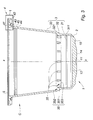
figure 1 est une vue isométrique de la capsule représentée en position debout, la partie inférieure constituant le fond par lequel arrive le fluide chaud pour la préparation de la boisson et le dessus représenté sans son opercule étant le côté par lequel la préparation infusée sort de la capsule, - les
figures 2A ,2B, 2C montrent respectivement une vue de côté, une vue de dessus et une vue de dessous de la capsule, - la
figure 3 est une vue à échelle agrandie partielle en coupe axiale de la capsule, - la
figure 3A est une vue du détail I de lafigure 3 montrant la structure du bord de la capsule, - la
figure 3B est une vue agrandie de la partie inférieure de lafigure 3 , la capsule étant coupée selon un premier plan de coupe radial IIIB de lafigure 2B , - la
figure 3C est une vue agrandie de la partie inférieure de lafigure 3 , la capsule étant coupée selon un deuxième plan de coupe radial IIIC de lafigure 2B .
- the
figure 1 is an isometric view of the capsule shown in a standing position, the lower part constituting the bottom through which the hot fluid for the preparation of the beverage arrives and the top represented without its lid being the side by which the infused preparation leaves the capsule, - the
Figures 2A ,2B, 2C show respectively a side view, a top view and a bottom view of the capsule, - the
figure 3 is a partial enlarged view in axial section of the capsule, - the
figure 3A is a detail view I of thefigure 3 showing the structure of the edge of the capsule, - the
figure 3B is an enlarged view of the lower part of thefigure 3 , the capsule being cut in a first radial section plane IIIB of theFigure 2B , - the
figure 3C is an enlarged view of the lower part of thefigure 3 , the capsule being cut along a second radial section plane IIIC of theFigure 2B .
Selon la
Les
Le cône de base 2 rejoint le cône inférieur 31 rigidifiant la capsule près du fond. Le cône inférieur 31 est relié par l'intermédiaire de la jonction conique 32 à la paroi conique 33. La jonction conique 32 a une plus forte conicité que le cône inférieur 31 et la paroi conique 33 pour absorber sur une courte hauteur, la différence de diamètre par rapport au cône inférieur 31 qui permet l'emboitement de capsules vides tout en restant, par sa paroi latérale 3, dans une enveloppe tronconique. Intérieurement, la jonction 32 du cône inférieur 31 et de la paroi conique 33, est munie de consoles d'emboitement 35 dont le côté montant 351 prolonge la surface intérieure du cône inférieur 31 et le côté supérieur 352 forme une surface d'appui d'emboitement (
La
La vue de dessus de la
Comme le montrent de façon plus détaillée les
La couronne intérieure 44 a également une section triangulaire à sommet arrondi avec un angle de l'ordre de 40° et l'intervalle des deux couronnes 43, 44 est occupée par la lèvre d'étanchéité 45 qui a également une section triangulaire à sommet vif avec un angle de l'ordre de 40° de sorte que cette lèvre d'étanchéité 45 relativement haute, peut être écrasée avec un bon contact contre le bord P par ailleurs appuyé contre les couronnes 43, 44.The
La
La jonction du fond 1 et de la paroi latérale 3 est renforcée par la forme très ouverte du cône de base 2 dont la paroi a sensiblement l'épaisseur de la paroi latérale 3.The junction of the
En dessous de la paroi latérale 3, la
Les
Le fond 1 relié au cône de base 2 a une forme de révolution, complexe, tant dans le secteur séparant deux nervures 12, qu'au niveau des nervures 12.The bottom 1 connected to the
Selon les
Le disque central 14 est situé extérieurement dans le plan PO perpendiculaire à l'axe xx alors que la couronne extérieure 15 est située dans un plan P1, également perpendiculaire à l'axe xx, mais au-dessus du plan P0, c'est-à-dire en retrait vers l'intérieur de la capsule ; la couronne intermédiaire 13 a ainsi une forme tronconique faisant la jonction entre les deux plans P0, P1 avec toutefois un décrochement extérieur 131 à la jonction des couronnes 13, 15 et intérieurement un prolongement radial intérieur ou rentrant 132 de la couronne 15 pour soutenir la jonction du bord de la couronne intermédiaire 13 contre la poussée des picots et la pression du fluide chaud. Ce renforcement évite toute amorce de déchirure de la membrane à sa jonction avec la couronne extérieure 15.The
De façon avantageuse, la surface intérieure de la couronne périphérique 15 et celle du disque central 14, hors dôme 11, est dans un même plan P2 perpendiculaire à l'axe xx.Advantageously, the inner surface of the
Les
Côté intérieur, la nervure 12 a un bord 122, droit, contenu dans un plan perpendiculaire à l'axe xx ; ce côté 122 dépasse les différents reliefs intérieurs du fond et rejoint le cône de base 2 en reliant ainsi le disque central 14 et la couronne extérieure 15.On the inside, the
Grâce à ces différentes formes de renforcement, la capsule C est rigidifiée et le fond 1 résiste à la poussée des broches du piston et ne se déforme pas, évitant l'écrasement de la capsule, favorisant son percement par les picots du piston et permettant une meilleure compression de la substance, notamment du café, c'est-à-dire pas de perte de pression et ainsi une meilleure extraction.Thanks to these different forms of reinforcement, the capsule C is stiffened and the
L'ossature du fond 1 est rigide et protège les secteurs de percement, fragilisés intentionnellement, pour éviter toute rupture accidentelle au cours des manipulations dans les machines de chargement et de scellement des capsules, ou pendant les opérations de conditionnement ou même lors de la mise en place de la capsule dans la chambre de la machine à café.The frame of the
Enfin, le fond 1, facilite la tenue de la capsule C debout sur son fond 1 ayant une surface plane 14 importante (plan PO).Finally, the
La capsule C telle que décrite se réalise très simplement par injection ou emboutissage d'une matière plastique de qualité alimentaire. Elle s'empile facilement après sa fabrication et se désempile tout aussi simplement pour son remplissage.The capsule C as described is made very simply by injection or stamping a food grade plastic material. It is easily stacked after its manufacture and is simply unstacked for filling.
- CVS
- CapsuleCapsule
- PP
- Bord du pistonPiston edge
- P0P0
-
Plan extérieur du disque central du fond 1Outline of the central disk of the
bottom 1 - P1P1
-
Plan extérieur de la couronne extérieure 15Outer plan of the
outer ring 15 - P2P2
-
Plan de la surface intérieure du fond 1 et de la couronne extérieure 15Plan of the inner surface of the
bottom 1 and theouter ring 15 - P3P3
-
Plan du dessus des nervures 12Top plan of the
ribs 12 - xxxx
- Axe de la capsuleAxis of the capsule
- 11
- FondBackground
- 1111
- DômeDome
- 1212
- Nervure radialeRadial rib
- 1313
- Couronne intermédiaire divisée en secteursIntermediate Crown divided into sectors
- 131131
- Décrochement extérieurOffset
- 132132
- Prolongement radial intérieurInternal radial extension
- 1414
- Disque centralCentral disk
- 1515
- Couronne périphériquePeripheral Crown
- 22
- Cône de baseBasic cone
- 2121
- ArrêteStopped
- 2323
- JonctionJunction
- 33
- Paroi latéraleSide wall
- 3131
- Cône inférieurLower cone
- 311311
- Nervure périphériquePeripheral rib
- 3232
- Jonction coniqueConical junction
- 321321
- Ligne de réunionMeeting line
- 3333
- Paroi principale coniqueConical main wall
- 3434
- Nervure périphériquePeripheral rib
- 3535
- ConsoleConsole
- 351351
- Côté montantAmount side
- 352352
- Côté supérieurUpper side
- 353353
- Arrête d'appuiStop support
- 44
- RebordFlange
- 4141
- Surface supérieureUpper surface
- 4242
- Couronne de rigidificationCrown of stiffening
- 4343
- Couronne extérieureOuter crown
- 4444
- Couronne intérieureInner crown
- 4545
- Lèvre d'étanchéitéSealing lip
- 55
- Operculeoperculum
Claims (12)
le fond (1) est formé par
the bottom (1) is formed by
caractérisée en ce que
la paroi latérale (3) est reliée au cône de base (2) solidaire du fond (1) par un cône inférieur (31) de très faible conicité (ΔC).Capsule according to claim 1,
characterized in that
the side wall (3) is connected to the base cone (2) integral with the bottom (1) by a lower cone (31) of very small conicity (ΔC).
caractérisée en ce que
la surface extérieure du disque central (14) est plane (plan P0) de même que la surface extérieure de la couronne périphérique (15) (plan P1), la plan (P1) étant perpendiculaire à l'axe (xx) comme le plan (P0) tout en étant en retrait par rapport à ce dernier, et
la couronne intermédiaire (13) a une face de tronc de cône rejoignant le disque central (14) et la couronne extérieure (15).Capsule according to claim 1,
characterized in that
the outer surface of the central disk (14) is plane (plane P0) as is the outer surface of the peripheral ring (15) (plane P1), the plane (P1) being perpendicular to the axis (xx) as the plane (P0) while being set back from the latter, and
the intermediate ring (13) has a truncated cone face joining the central disk (14) and the outer ring (15).
caractérisée en ce que
la jonction extérieure entre la couronne intermédiaire (13) et de la couronne extérieure (15) forme un décrochement rentrant (131) et la jonction intérieure se fait avec le prolongement radial intérieur (132) de la couronne extérieure (15).Capsule according to claim 3,
characterized in that
the outer junction between the intermediate ring (13) and the outer ring (15) forms a retracting recess (131) and the inner junction is made with the inner radial extension (132) of the outer ring (15).
caractérisée en ce que
la nervure (12) a un bord (122) côté intérieur dans le plan (P3) perpendiculaire à l'axe (xx) de sorte que la nervure (12) rejoint par son dessus (122), le cône de base (2).Capsule according to claim 1,
characterized in that
the rib (12) has an edge (122) on the inner side in the plane (P3) perpendicular to the axis (xx) so that the rib (12) joins from above (122) the base cone (2) .
caractérisée en ce que
le fond (1) comporte plusieurs nervures radiales (12) le divisant en secteurs de couronne circulaire, notamment quatre secteurs.Capsule according to claim 1,
characterized in that
the bottom (1) has a plurality of radial ribs (12) dividing it into circular ring sectors, in particular four sectors.
caractérisée en ce que
la jonction conique (32) au-dessus du cylindre (31) de la paroi (3) comporte, sur sa surface intérieure, des consoles d'emboitement (35) ayant un côté montant (351) et un côté supérieur (352) se coupant en formant une arrête d'appui (353) constituant avec le côté supérieur (352), une surface d'appui périphérique sur laquelle s'appuie le cône de base (2) de la capsule vide emboîtée.Capsule according to claim 1,
characterized in that
the conical junction (32) above the cylinder (31) of the wall (3) has, on its inner surface, interlocking brackets (35) having a rising side (351) and an upper side (352) cutting by forming a support stop (353) constituting with the upper side (352), a peripheral bearing surface on which rests the base cone (2) of the empty capsule nested.
caractérisée en ce que
l'arête (21) à la réunion du cône de base (2) et du cylindre (31) est en retrait par rapport au prolongement du tronc de cône géométrique de la paroi conique (33).Capsule according to claim 1,
characterized in that
the edge (21) at the meeting of the base cone (2) and the cylinder (31) is recessed relative to the extension of the geometric conical frustum of the conical wall (33).
caractérisée en ce que
sur sa surface intérieure, le cylindre de base (31) a une nervure de rigidification, périphérique (311).Capsule according to claim 1,
characterized in that
on its inner surface, the base cylinder (31) has a peripheral stiffening rib (311).
caractérisée en ce que
le fond (1) a une épaisseur augmentée par rapport à celle de la paroi latérale (3) notamment une épaisseur de l'ordre de 1 mm et la couronne intermédiaire (13) a une épaisseur de l'ordre de 1/5ème de l'épaisseur du fond (1).Capsule according to claim 1,
characterized in that
the bottom (1) has an increased thickness relative to that of the side wall (3) in particular a thickness of the order of 1 mm and the intermediate ring (13) has a thickness of the order of 1/5 th of the thickness of the bottom (1).
caractérisée en ce que
le dessous du rebord (4) recevant le bord (P) du piston de la machine d'extraction comporte une couronne de rigidification (42) et une couronne extérieure (43) définissant avec une couronne intérieure (44) près de la paroi latérale (3), un intervalle avec une lèvre d'étanchéité (45) également en forme de section triangulaire, pour former la surface de réception du bord (P) du piston de la machine d'extraction.Capsule according to claim 1,
characterized in that
the underside of the rim (4) receiving the edge (P) of the piston of the extraction machine comprises a stiffening ring (42) and an outer ring (43) defining with an inner ring (44) near the side wall ( 3), an interval with a sealing lip (45) also shaped triangular section, to form the receiving surface of the edge (P) of the piston of the extraction machine.
caractérisée en ce que
la couronne extérieure (43), la couronne intérieure (44) et la lèvre (45) ont une section triangulaire avec un angle au sommet de l'ordre de 40°.Capsule according to claim 8,
characterized in that
the outer ring (43), the inner ring (44) and the lip (45) have a triangular section with an apex angle of the order of 40 °.
Applications Claiming Priority (1)
| Application Number | Priority Date | Filing Date | Title |
|---|---|---|---|
| LU92497A LU92497B1 (en) | 2014-07-10 | 2014-07-10 | NON-PRE-PUNCHED CAPSULE FOR THE PREPARATION OF A BEVERAGE |
Publications (2)
| Publication Number | Publication Date |
|---|---|
| EP2966006A1 true EP2966006A1 (en) | 2016-01-13 |
| EP2966006B1 EP2966006B1 (en) | 2017-08-16 |
Family
ID=51228469
Family Applications (1)
| Application Number | Title | Priority Date | Filing Date |
|---|---|---|---|
| EP15176075.8A Not-in-force EP2966006B1 (en) | 2014-07-10 | 2015-07-09 | Non pre-pierced capsule for preparing a beverage |
Country Status (6)
| Country | Link |
|---|---|
| EP (1) | EP2966006B1 (en) |
| AU (1) | AU2015203869B2 (en) |
| BR (1) | BR102015016655B1 (en) |
| ES (1) | ES2647598T3 (en) |
| IL (1) | IL239902B (en) |
| LU (1) | LU92497B1 (en) |
Cited By (11)
| Publication number | Priority date | Publication date | Assignee | Title |
|---|---|---|---|---|
| EP3181484A1 (en) * | 2015-12-16 | 2017-06-21 | Mühlemann IP GmbH | Capsule cup of a coffee capsule |
| ITUA20162114A1 (en) * | 2016-03-30 | 2017-09-30 | Faps Eng Sa | CAPSULE FOR BEVERAGE DISTRIBUTION. |
| WO2018046715A1 (en) * | 2016-09-09 | 2018-03-15 | Xpressivo Ag | Capsule with arc shape between capsule wall and capsule base |
| DE102018008119A1 (en) * | 2017-10-27 | 2019-05-02 | Kiefel Packaging B.V. | OF A FILM OF THERMOFORMED TANKS, USE OF A METHOD FOR THERMOFORMS OF A FILM, USE OF A TOOLING TOOL |
| WO2019185637A1 (en) | 2018-03-26 | 2019-10-03 | Brain Corp Sa | Capsule intended for receiving a substance for preparing a beverage |
| LU101279B1 (en) | 2019-06-24 | 2020-12-28 | Brain Corp Sa | Capsule for the preparation of a drink |
| WO2020260300A1 (en) | 2019-06-24 | 2020-12-30 | Brain Corp Sa | Capsule for preparing a beverage |
| LU101633B1 (en) | 2020-02-03 | 2021-08-03 | Brain Corp Sa | Capsule intended to contain a substance for the preparation of a drink |
| WO2021191178A1 (en) | 2020-03-23 | 2021-09-30 | Basf Se | Container for ingredients for making beverages |
| LU102246B1 (en) | 2020-11-30 | 2022-05-30 | Brain Corp Sa | Assembly comprising a capsule intended to receive a substance for the preparation of a drink and a lid |
| US11504898B2 (en) | 2017-10-27 | 2022-11-22 | Kiefel Gmbh | Method of thermoforming a foil, forming tool, thermoforming tool, installation for thermoforming, container and brewing container |
Citations (6)
| Publication number | Priority date | Publication date | Assignee | Title |
|---|---|---|---|---|
| FR1257144A (en) | 1960-02-17 | 1961-03-31 | Regulation Automatique | Solenoid valve with flow control |
| WO2004087529A1 (en) * | 2003-04-02 | 2004-10-14 | Hausbrandt Trieste 1892 Spa | Single-dose plastic capsule for powdered coffee and the like |
| WO2011154672A1 (en) * | 2010-06-11 | 2011-12-15 | Alain Frydman | Capsule for pressurised drink extraction |
| WO2011154666A1 (en) * | 2010-06-11 | 2011-12-15 | Alain Frydman | Two-material capsule |
| EP2465793A1 (en) * | 2010-12-20 | 2012-06-20 | Macchiavelli S.r.l. | Capsule for infusion products |
| FR2993869A1 (en) * | 2012-07-24 | 2014-01-31 | Brain Corp S A | Capsule for receiving substance i.e. coffee powder, for preparation of coffee in e.g. coffee machine, has perforated bottom rigidified by circular flange that projects towards interior of capsule, where bottom is provided with holes |
-
2014
- 2014-07-10 LU LU92497A patent/LU92497B1/en active
-
2015
- 2015-07-09 AU AU2015203869A patent/AU2015203869B2/en not_active Ceased
- 2015-07-09 IL IL239902A patent/IL239902B/en active IP Right Grant
- 2015-07-09 EP EP15176075.8A patent/EP2966006B1/en not_active Not-in-force
- 2015-07-09 ES ES15176075.8T patent/ES2647598T3/en active Active
- 2015-07-10 BR BR102015016655-9A patent/BR102015016655B1/en not_active IP Right Cessation
Patent Citations (6)
| Publication number | Priority date | Publication date | Assignee | Title |
|---|---|---|---|---|
| FR1257144A (en) | 1960-02-17 | 1961-03-31 | Regulation Automatique | Solenoid valve with flow control |
| WO2004087529A1 (en) * | 2003-04-02 | 2004-10-14 | Hausbrandt Trieste 1892 Spa | Single-dose plastic capsule for powdered coffee and the like |
| WO2011154672A1 (en) * | 2010-06-11 | 2011-12-15 | Alain Frydman | Capsule for pressurised drink extraction |
| WO2011154666A1 (en) * | 2010-06-11 | 2011-12-15 | Alain Frydman | Two-material capsule |
| EP2465793A1 (en) * | 2010-12-20 | 2012-06-20 | Macchiavelli S.r.l. | Capsule for infusion products |
| FR2993869A1 (en) * | 2012-07-24 | 2014-01-31 | Brain Corp S A | Capsule for receiving substance i.e. coffee powder, for preparation of coffee in e.g. coffee machine, has perforated bottom rigidified by circular flange that projects towards interior of capsule, where bottom is provided with holes |
Cited By (16)
| Publication number | Priority date | Publication date | Assignee | Title |
|---|---|---|---|---|
| WO2017103028A1 (en) * | 2015-12-16 | 2017-06-22 | Mühlemann Ip Gmbh | Casing of a coffee capsule |
| EP3181484A1 (en) * | 2015-12-16 | 2017-06-21 | Mühlemann IP GmbH | Capsule cup of a coffee capsule |
| ITUA20162114A1 (en) * | 2016-03-30 | 2017-09-30 | Faps Eng Sa | CAPSULE FOR BEVERAGE DISTRIBUTION. |
| EP3225569A1 (en) * | 2016-03-30 | 2017-10-04 | Faps Engineering Sa | Capsule for delivering beverages |
| WO2018046715A1 (en) * | 2016-09-09 | 2018-03-15 | Xpressivo Ag | Capsule with arc shape between capsule wall and capsule base |
| US11504898B2 (en) | 2017-10-27 | 2022-11-22 | Kiefel Gmbh | Method of thermoforming a foil, forming tool, thermoforming tool, installation for thermoforming, container and brewing container |
| DE102018008119A1 (en) * | 2017-10-27 | 2019-05-02 | Kiefel Packaging B.V. | OF A FILM OF THERMOFORMED TANKS, USE OF A METHOD FOR THERMOFORMS OF A FILM, USE OF A TOOLING TOOL |
| DE102018008119B4 (en) * | 2017-10-27 | 2019-06-06 | Kiefel Packaging B.V. | OF A FILM OF THERMOFORMED TANKS, USE OF A METHOD FOR THERMOFORMS OF A FILM, USE OF A TOOLING TOOL |
| WO2019185637A1 (en) | 2018-03-26 | 2019-10-03 | Brain Corp Sa | Capsule intended for receiving a substance for preparing a beverage |
| LU101279B1 (en) | 2019-06-24 | 2020-12-28 | Brain Corp Sa | Capsule for the preparation of a drink |
| WO2020260300A1 (en) | 2019-06-24 | 2020-12-30 | Brain Corp Sa | Capsule for preparing a beverage |
| DE202020005896U1 (en) | 2019-06-24 | 2023-02-06 | Brain Corp S.A. | Capsule for making a drink |
| LU101633B1 (en) | 2020-02-03 | 2021-08-03 | Brain Corp Sa | Capsule intended to contain a substance for the preparation of a drink |
| WO2021191178A1 (en) | 2020-03-23 | 2021-09-30 | Basf Se | Container for ingredients for making beverages |
| LU102246B1 (en) | 2020-11-30 | 2022-05-30 | Brain Corp Sa | Assembly comprising a capsule intended to receive a substance for the preparation of a drink and a lid |
| WO2022112613A1 (en) | 2020-11-30 | 2022-06-02 | Brain Corp Sa | Assembly comprising a capsule intended to receive a substance for preparing a beverage, and a film lid |
Also Published As
| Publication number | Publication date |
|---|---|
| AU2015203869A1 (en) | 2016-01-28 |
| BR102015016655A2 (en) | 2016-07-19 |
| IL239902B (en) | 2019-07-31 |
| EP2966006B1 (en) | 2017-08-16 |
| AU2015203869B2 (en) | 2017-06-01 |
| BR102015016655B1 (en) | 2021-01-26 |
| LU92497B1 (en) | 2016-01-11 |
| ES2647598T3 (en) | 2017-12-22 |
Similar Documents
| Publication | Publication Date | Title |
|---|---|---|
| EP2966006B1 (en) | Non pre-pierced capsule for preparing a beverage | |
| EP2923969B1 (en) | Capsule for preparing a beverage | |
| EP2690035B1 (en) | Capsule for preparing a beverage such as a coffee capsule | |
| EP0524464B1 (en) | Flexible coffee cartridge with a rigidifying element and method of manufacturing the same | |
| EP2651778B1 (en) | Capsule having a variable frustoconical shape for extracting a beverage under pressure | |
| JP6797682B2 (en) | Beverage capsule | |
| EP2643231B1 (en) | Device for stopping a container, and container provided with such a device | |
| LU93172B1 (en) | Capsule for the preparation of a drink | |
| FR2993869A1 (en) | Capsule for receiving substance i.e. coffee powder, for preparation of coffee in e.g. coffee machine, has perforated bottom rigidified by circular flange that projects towards interior of capsule, where bottom is provided with holes | |
| EP3027524B1 (en) | Cap for a receptacle and receptacle, in particular tube, in particular flexible tube for a cosmetic product, provided with said cap | |
| FR2989258A1 (en) | REINFORCED CAPSULE FOR PERCOLATING A PRODUCT SUCH AS COFFEE | |
| BE1000161A6 (en) | Coffee cup or similar beverages, synthetic thermoplastic. | |
| EP2782848B1 (en) | Capsule for the pressurized extraction of a beverage, including a fluid inlet wall provided so as to be ruptured by a pressurized fluid | |
| EP2718198A1 (en) | Stopping device and container comprising such a device | |
| LU92840B1 (en) | Capsule for the preparation of a beverage such as coffee or an infusion | |
| FR3018270A1 (en) | CAPSULE FOR PREPARING A BEVERAGE | |
| LU92810B1 (en) | SEALED BASE CAPSULE FOR PREPARING A BEVERAGE |
Legal Events
| Date | Code | Title | Description |
|---|---|---|---|
| PUAI | Public reference made under article 153(3) epc to a published international application that has entered the european phase |
Free format text: ORIGINAL CODE: 0009012 |
|
| AK | Designated contracting states |
Kind code of ref document: A1 Designated state(s): AL AT BE BG CH CY CZ DE DK EE ES FI FR GB GR HR HU IE IS IT LI LT LU LV MC MK MT NL NO PL PT RO RS SE SI SK SM TR |
|
| AX | Request for extension of the european patent |
Extension state: BA ME |
|
| 17P | Request for examination filed |
Effective date: 20160711 |
|
| RBV | Designated contracting states (corrected) |
Designated state(s): AL AT BE BG CH CY CZ DE DK EE ES FI FR GB GR HR HU IE IS IT LI LT LU LV MC MK MT NL NO PL PT RO RS SE SI SK SM TR |
|
| GRAP | Despatch of communication of intention to grant a patent |
Free format text: ORIGINAL CODE: EPIDOSNIGR1 |
|
| STAA | Information on the status of an ep patent application or granted ep patent |
Free format text: STATUS: GRANT OF PATENT IS INTENDED |
|
| RIC1 | Information provided on ipc code assigned before grant |
Ipc: B65D 85/804 20060101AFI20170207BHEP |
|
| INTG | Intention to grant announced |
Effective date: 20170313 |
|
| GRAS | Grant fee paid |
Free format text: ORIGINAL CODE: EPIDOSNIGR3 |
|
| GRAA | (expected) grant |
Free format text: ORIGINAL CODE: 0009210 |
|
| STAA | Information on the status of an ep patent application or granted ep patent |
Free format text: STATUS: THE PATENT HAS BEEN GRANTED |
|
| AK | Designated contracting states |
Kind code of ref document: B1 Designated state(s): AL AT BE BG CH CY CZ DE DK EE ES FI FR GB GR HR HU IE IS IT LI LT LU LV MC MK MT NL NO PL PT RO RS SE SI SK SM TR |
|
| REG | Reference to a national code |
Ref country code: GB Ref legal event code: FG4D Free format text: NOT ENGLISH |
|
| REG | Reference to a national code |
Ref country code: CH Ref legal event code: EP |
|
| REG | Reference to a national code |
Ref country code: IE Ref legal event code: FG4D Free format text: LANGUAGE OF EP DOCUMENT: FRENCH |
|
| REG | Reference to a national code |
Ref country code: AT Ref legal event code: REF Ref document number: 918811 Country of ref document: AT Kind code of ref document: T Effective date: 20170915 |
|
| REG | Reference to a national code |
Ref country code: DE Ref legal event code: R096 Ref document number: 602015004113 Country of ref document: DE |
|
| REG | Reference to a national code |
Ref country code: NL Ref legal event code: MP Effective date: 20170816 |
|
| REG | Reference to a national code |
Ref country code: ES Ref legal event code: FG2A Ref document number: 2647598 Country of ref document: ES Kind code of ref document: T3 Effective date: 20171222 |
|
| REG | Reference to a national code |
Ref country code: LT Ref legal event code: MG4D |
|
| REG | Reference to a national code |
Ref country code: AT Ref legal event code: MK05 Ref document number: 918811 Country of ref document: AT Kind code of ref document: T Effective date: 20170816 |
|
| PG25 | Lapsed in a contracting state [announced via postgrant information from national office to epo] |
Ref country code: AT Free format text: LAPSE BECAUSE OF FAILURE TO SUBMIT A TRANSLATION OF THE DESCRIPTION OR TO PAY THE FEE WITHIN THE PRESCRIBED TIME-LIMIT Effective date: 20170816 Ref country code: FI Free format text: LAPSE BECAUSE OF FAILURE TO SUBMIT A TRANSLATION OF THE DESCRIPTION OR TO PAY THE FEE WITHIN THE PRESCRIBED TIME-LIMIT Effective date: 20170816 Ref country code: SE Free format text: LAPSE BECAUSE OF FAILURE TO SUBMIT A TRANSLATION OF THE DESCRIPTION OR TO PAY THE FEE WITHIN THE PRESCRIBED TIME-LIMIT Effective date: 20170816 Ref country code: NO Free format text: LAPSE BECAUSE OF FAILURE TO SUBMIT A TRANSLATION OF THE DESCRIPTION OR TO PAY THE FEE WITHIN THE PRESCRIBED TIME-LIMIT Effective date: 20171116 Ref country code: NL Free format text: LAPSE BECAUSE OF FAILURE TO SUBMIT A TRANSLATION OF THE DESCRIPTION OR TO PAY THE FEE WITHIN THE PRESCRIBED TIME-LIMIT Effective date: 20170816 Ref country code: LT Free format text: LAPSE BECAUSE OF FAILURE TO SUBMIT A TRANSLATION OF THE DESCRIPTION OR TO PAY THE FEE WITHIN THE PRESCRIBED TIME-LIMIT Effective date: 20170816 |
|
| PG25 | Lapsed in a contracting state [announced via postgrant information from national office to epo] |
Ref country code: LV Free format text: LAPSE BECAUSE OF FAILURE TO SUBMIT A TRANSLATION OF THE DESCRIPTION OR TO PAY THE FEE WITHIN THE PRESCRIBED TIME-LIMIT Effective date: 20170816 Ref country code: BG Free format text: LAPSE BECAUSE OF FAILURE TO SUBMIT A TRANSLATION OF THE DESCRIPTION OR TO PAY THE FEE WITHIN THE PRESCRIBED TIME-LIMIT Effective date: 20171116 Ref country code: PL Free format text: LAPSE BECAUSE OF FAILURE TO SUBMIT A TRANSLATION OF THE DESCRIPTION OR TO PAY THE FEE WITHIN THE PRESCRIBED TIME-LIMIT Effective date: 20170816 Ref country code: GR Free format text: LAPSE BECAUSE OF FAILURE TO SUBMIT A TRANSLATION OF THE DESCRIPTION OR TO PAY THE FEE WITHIN THE PRESCRIBED TIME-LIMIT Effective date: 20171117 Ref country code: IS Free format text: LAPSE BECAUSE OF FAILURE TO SUBMIT A TRANSLATION OF THE DESCRIPTION OR TO PAY THE FEE WITHIN THE PRESCRIBED TIME-LIMIT Effective date: 20171216 Ref country code: RS Free format text: LAPSE BECAUSE OF FAILURE TO SUBMIT A TRANSLATION OF THE DESCRIPTION OR TO PAY THE FEE WITHIN THE PRESCRIBED TIME-LIMIT Effective date: 20170816 |
|
| PG25 | Lapsed in a contracting state [announced via postgrant information from national office to epo] |
Ref country code: DK Free format text: LAPSE BECAUSE OF FAILURE TO SUBMIT A TRANSLATION OF THE DESCRIPTION OR TO PAY THE FEE WITHIN THE PRESCRIBED TIME-LIMIT Effective date: 20170816 Ref country code: CZ Free format text: LAPSE BECAUSE OF FAILURE TO SUBMIT A TRANSLATION OF THE DESCRIPTION OR TO PAY THE FEE WITHIN THE PRESCRIBED TIME-LIMIT Effective date: 20170816 Ref country code: RO Free format text: LAPSE BECAUSE OF FAILURE TO SUBMIT A TRANSLATION OF THE DESCRIPTION OR TO PAY THE FEE WITHIN THE PRESCRIBED TIME-LIMIT Effective date: 20170816 |
|
| REG | Reference to a national code |
Ref country code: DE Ref legal event code: R097 Ref document number: 602015004113 Country of ref document: DE |
|
| PG25 | Lapsed in a contracting state [announced via postgrant information from national office to epo] |
Ref country code: SM Free format text: LAPSE BECAUSE OF FAILURE TO SUBMIT A TRANSLATION OF THE DESCRIPTION OR TO PAY THE FEE WITHIN THE PRESCRIBED TIME-LIMIT Effective date: 20170816 Ref country code: SK Free format text: LAPSE BECAUSE OF FAILURE TO SUBMIT A TRANSLATION OF THE DESCRIPTION OR TO PAY THE FEE WITHIN THE PRESCRIBED TIME-LIMIT Effective date: 20170816 Ref country code: EE Free format text: LAPSE BECAUSE OF FAILURE TO SUBMIT A TRANSLATION OF THE DESCRIPTION OR TO PAY THE FEE WITHIN THE PRESCRIBED TIME-LIMIT Effective date: 20170816 |
|
| PLBE | No opposition filed within time limit |
Free format text: ORIGINAL CODE: 0009261 |
|
| STAA | Information on the status of an ep patent application or granted ep patent |
Free format text: STATUS: NO OPPOSITION FILED WITHIN TIME LIMIT |
|
| 26N | No opposition filed |
Effective date: 20180517 |
|
| REG | Reference to a national code |
Ref country code: FR Ref legal event code: PLFP Year of fee payment: 4 |
|
| PG25 | Lapsed in a contracting state [announced via postgrant information from national office to epo] |
Ref country code: SI Free format text: LAPSE BECAUSE OF FAILURE TO SUBMIT A TRANSLATION OF THE DESCRIPTION OR TO PAY THE FEE WITHIN THE PRESCRIBED TIME-LIMIT Effective date: 20170816 |
|
| PG25 | Lapsed in a contracting state [announced via postgrant information from national office to epo] |
Ref country code: MT Free format text: LAPSE BECAUSE OF FAILURE TO SUBMIT A TRANSLATION OF THE DESCRIPTION OR TO PAY THE FEE WITHIN THE PRESCRIBED TIME-LIMIT Effective date: 20170816 |
|
| REG | Reference to a national code |
Ref country code: CH Ref legal event code: PL |
|
| PG25 | Lapsed in a contracting state [announced via postgrant information from national office to epo] |
Ref country code: MC Free format text: LAPSE BECAUSE OF FAILURE TO SUBMIT A TRANSLATION OF THE DESCRIPTION OR TO PAY THE FEE WITHIN THE PRESCRIBED TIME-LIMIT Effective date: 20170816 Ref country code: LU Free format text: LAPSE BECAUSE OF NON-PAYMENT OF DUE FEES Effective date: 20180709 |
|
| REG | Reference to a national code |
Ref country code: BE Ref legal event code: MM Effective date: 20180731 |
|
| REG | Reference to a national code |
Ref country code: IE Ref legal event code: MM4A |
|
| PG25 | Lapsed in a contracting state [announced via postgrant information from national office to epo] |
Ref country code: LI Free format text: LAPSE BECAUSE OF NON-PAYMENT OF DUE FEES Effective date: 20180731 Ref country code: CH Free format text: LAPSE BECAUSE OF NON-PAYMENT OF DUE FEES Effective date: 20180731 Ref country code: IE Free format text: LAPSE BECAUSE OF NON-PAYMENT OF DUE FEES Effective date: 20180709 |
|
| PG25 | Lapsed in a contracting state [announced via postgrant information from national office to epo] |
Ref country code: BE Free format text: LAPSE BECAUSE OF NON-PAYMENT OF DUE FEES Effective date: 20180731 |
|
| PG25 | Lapsed in a contracting state [announced via postgrant information from national office to epo] |
Ref country code: TR Free format text: LAPSE BECAUSE OF FAILURE TO SUBMIT A TRANSLATION OF THE DESCRIPTION OR TO PAY THE FEE WITHIN THE PRESCRIBED TIME-LIMIT Effective date: 20170816 |
|
| PG25 | Lapsed in a contracting state [announced via postgrant information from national office to epo] |
Ref country code: PT Free format text: LAPSE BECAUSE OF FAILURE TO SUBMIT A TRANSLATION OF THE DESCRIPTION OR TO PAY THE FEE WITHIN THE PRESCRIBED TIME-LIMIT Effective date: 20170816 |
|
| PG25 | Lapsed in a contracting state [announced via postgrant information from national office to epo] |
Ref country code: HU Free format text: LAPSE BECAUSE OF FAILURE TO SUBMIT A TRANSLATION OF THE DESCRIPTION OR TO PAY THE FEE WITHIN THE PRESCRIBED TIME-LIMIT; INVALID AB INITIO Effective date: 20150709 Ref country code: MK Free format text: LAPSE BECAUSE OF NON-PAYMENT OF DUE FEES Effective date: 20170816 Ref country code: CY Free format text: LAPSE BECAUSE OF FAILURE TO SUBMIT A TRANSLATION OF THE DESCRIPTION OR TO PAY THE FEE WITHIN THE PRESCRIBED TIME-LIMIT Effective date: 20170816 Ref country code: HR Free format text: LAPSE BECAUSE OF FAILURE TO SUBMIT A TRANSLATION OF THE DESCRIPTION OR TO PAY THE FEE WITHIN THE PRESCRIBED TIME-LIMIT Effective date: 20170816 |
|
| PG25 | Lapsed in a contracting state [announced via postgrant information from national office to epo] |
Ref country code: AL Free format text: LAPSE BECAUSE OF FAILURE TO SUBMIT A TRANSLATION OF THE DESCRIPTION OR TO PAY THE FEE WITHIN THE PRESCRIBED TIME-LIMIT Effective date: 20170816 |
|
| PGFP | Annual fee paid to national office [announced via postgrant information from national office to epo] |
Ref country code: GB Payment date: 20200722 Year of fee payment: 6 Ref country code: DE Payment date: 20200716 Year of fee payment: 6 Ref country code: ES Payment date: 20200817 Year of fee payment: 6 |
|
| PGFP | Annual fee paid to national office [announced via postgrant information from national office to epo] |
Ref country code: IT Payment date: 20200714 Year of fee payment: 6 |
|
| PGFP | Annual fee paid to national office [announced via postgrant information from national office to epo] |
Ref country code: FR Payment date: 20210730 Year of fee payment: 7 |
|
| REG | Reference to a national code |
Ref country code: DE Ref legal event code: R119 Ref document number: 602015004113 Country of ref document: DE |
|
| GBPC | Gb: european patent ceased through non-payment of renewal fee |
Effective date: 20210709 |
|
| PG25 | Lapsed in a contracting state [announced via postgrant information from national office to epo] |
Ref country code: GB Free format text: LAPSE BECAUSE OF NON-PAYMENT OF DUE FEES Effective date: 20210709 Ref country code: DE Free format text: LAPSE BECAUSE OF NON-PAYMENT OF DUE FEES Effective date: 20220201 |
|
| PG25 | Lapsed in a contracting state [announced via postgrant information from national office to epo] |
Ref country code: IT Free format text: LAPSE BECAUSE OF NON-PAYMENT OF DUE FEES Effective date: 20210709 |
|
| REG | Reference to a national code |
Ref country code: ES Ref legal event code: FD2A Effective date: 20220901 |
|
| PG25 | Lapsed in a contracting state [announced via postgrant information from national office to epo] |
Ref country code: ES Free format text: LAPSE BECAUSE OF NON-PAYMENT OF DUE FEES Effective date: 20210710 |
|
| PG25 | Lapsed in a contracting state [announced via postgrant information from national office to epo] |
Ref country code: FR Free format text: LAPSE BECAUSE OF NON-PAYMENT OF DUE FEES Effective date: 20220731 |