EP2965941B1 - Primärteil für ein induktives Ladegerät - Google Patents
Primärteil für ein induktives Ladegerät Download PDFInfo
- Publication number
- EP2965941B1 EP2965941B1 EP14176348.2A EP14176348A EP2965941B1 EP 2965941 B1 EP2965941 B1 EP 2965941B1 EP 14176348 A EP14176348 A EP 14176348A EP 2965941 B1 EP2965941 B1 EP 2965941B1
- Authority
- EP
- European Patent Office
- Prior art keywords
- primary
- primary section
- chimney
- coil
- section according
- Prior art date
- Legal status (The legal status is an assumption and is not a legal conclusion. Google has not performed a legal analysis and makes no representation as to the accuracy of the status listed.)
- Active
Links
- 230000001939 inductive effect Effects 0.000 title claims description 16
- 238000001816 cooling Methods 0.000 claims description 27
- 230000005540 biological transmission Effects 0.000 claims description 9
- 230000000630 rising effect Effects 0.000 claims description 5
- 230000007423 decrease Effects 0.000 claims description 2
- 230000000694 effects Effects 0.000 description 10
- 238000000034 method Methods 0.000 description 6
- 230000008569 process Effects 0.000 description 6
- 230000002093 peripheral effect Effects 0.000 description 3
- 238000009423 ventilation Methods 0.000 description 3
- 238000011109 contamination Methods 0.000 description 2
- 230000017525 heat dissipation Effects 0.000 description 2
- 238000010438 heat treatment Methods 0.000 description 2
- 230000001788 irregular Effects 0.000 description 2
- 101100498160 Mus musculus Dach1 gene Proteins 0.000 description 1
- 230000003044 adaptive effect Effects 0.000 description 1
- 238000010276 construction Methods 0.000 description 1
- 239000002826 coolant Substances 0.000 description 1
- 230000001419 dependent effect Effects 0.000 description 1
- 238000011161 development Methods 0.000 description 1
- 230000018109 developmental process Effects 0.000 description 1
- 230000003670 easy-to-clean Effects 0.000 description 1
- 238000004146 energy storage Methods 0.000 description 1
- 230000002708 enhancing effect Effects 0.000 description 1
- 230000005284 excitation Effects 0.000 description 1
- 230000006870 function Effects 0.000 description 1
- 230000006872 improvement Effects 0.000 description 1
- 239000000463 material Substances 0.000 description 1
- 239000012528 membrane Substances 0.000 description 1
- 239000007769 metal material Substances 0.000 description 1
- 238000005457 optimization Methods 0.000 description 1
- 230000001681 protective effect Effects 0.000 description 1
- 238000007493 shaping process Methods 0.000 description 1
- 238000000638 solvent extraction Methods 0.000 description 1
- 230000001052 transient effect Effects 0.000 description 1
- 230000007704 transition Effects 0.000 description 1
Images


Classifications
-
- H—ELECTRICITY
- H02—GENERATION; CONVERSION OR DISTRIBUTION OF ELECTRIC POWER
- H02J—CIRCUIT ARRANGEMENTS OR SYSTEMS FOR SUPPLYING OR DISTRIBUTING ELECTRIC POWER; SYSTEMS FOR STORING ELECTRIC ENERGY
- H02J50/00—Circuit arrangements or systems for wireless supply or distribution of electric power
- H02J50/10—Circuit arrangements or systems for wireless supply or distribution of electric power using inductive coupling
-
- B—PERFORMING OPERATIONS; TRANSPORTING
- B60—VEHICLES IN GENERAL
- B60L—PROPULSION OF ELECTRICALLY-PROPELLED VEHICLES; SUPPLYING ELECTRIC POWER FOR AUXILIARY EQUIPMENT OF ELECTRICALLY-PROPELLED VEHICLES; ELECTRODYNAMIC BRAKE SYSTEMS FOR VEHICLES IN GENERAL; MAGNETIC SUSPENSION OR LEVITATION FOR VEHICLES; MONITORING OPERATING VARIABLES OF ELECTRICALLY-PROPELLED VEHICLES; ELECTRIC SAFETY DEVICES FOR ELECTRICALLY-PROPELLED VEHICLES
- B60L53/00—Methods of charging batteries, specially adapted for electric vehicles; Charging stations or on-board charging equipment therefor; Exchange of energy storage elements in electric vehicles
- B60L53/10—Methods of charging batteries, specially adapted for electric vehicles; Charging stations or on-board charging equipment therefor; Exchange of energy storage elements in electric vehicles characterised by the energy transfer between the charging station and the vehicle
- B60L53/12—Inductive energy transfer
- B60L53/126—Methods for pairing a vehicle and a charging station, e.g. establishing a one-to-one relation between a wireless power transmitter and a wireless power receiver
-
- H—ELECTRICITY
- H01—ELECTRIC ELEMENTS
- H01F—MAGNETS; INDUCTANCES; TRANSFORMERS; SELECTION OF MATERIALS FOR THEIR MAGNETIC PROPERTIES
- H01F38/00—Adaptations of transformers or inductances for specific applications or functions
- H01F38/14—Inductive couplings
-
- Y—GENERAL TAGGING OF NEW TECHNOLOGICAL DEVELOPMENTS; GENERAL TAGGING OF CROSS-SECTIONAL TECHNOLOGIES SPANNING OVER SEVERAL SECTIONS OF THE IPC; TECHNICAL SUBJECTS COVERED BY FORMER USPC CROSS-REFERENCE ART COLLECTIONS [XRACs] AND DIGESTS
- Y02—TECHNOLOGIES OR APPLICATIONS FOR MITIGATION OR ADAPTATION AGAINST CLIMATE CHANGE
- Y02T—CLIMATE CHANGE MITIGATION TECHNOLOGIES RELATED TO TRANSPORTATION
- Y02T10/00—Road transport of goods or passengers
- Y02T10/60—Other road transportation technologies with climate change mitigation effect
- Y02T10/70—Energy storage systems for electromobility, e.g. batteries
-
- Y—GENERAL TAGGING OF NEW TECHNOLOGICAL DEVELOPMENTS; GENERAL TAGGING OF CROSS-SECTIONAL TECHNOLOGIES SPANNING OVER SEVERAL SECTIONS OF THE IPC; TECHNICAL SUBJECTS COVERED BY FORMER USPC CROSS-REFERENCE ART COLLECTIONS [XRACs] AND DIGESTS
- Y02—TECHNOLOGIES OR APPLICATIONS FOR MITIGATION OR ADAPTATION AGAINST CLIMATE CHANGE
- Y02T—CLIMATE CHANGE MITIGATION TECHNOLOGIES RELATED TO TRANSPORTATION
- Y02T10/00—Road transport of goods or passengers
- Y02T10/60—Other road transportation technologies with climate change mitigation effect
- Y02T10/7072—Electromobility specific charging systems or methods for batteries, ultracapacitors, supercapacitors or double-layer capacitors
-
- Y—GENERAL TAGGING OF NEW TECHNOLOGICAL DEVELOPMENTS; GENERAL TAGGING OF CROSS-SECTIONAL TECHNOLOGIES SPANNING OVER SEVERAL SECTIONS OF THE IPC; TECHNICAL SUBJECTS COVERED BY FORMER USPC CROSS-REFERENCE ART COLLECTIONS [XRACs] AND DIGESTS
- Y02—TECHNOLOGIES OR APPLICATIONS FOR MITIGATION OR ADAPTATION AGAINST CLIMATE CHANGE
- Y02T—CLIMATE CHANGE MITIGATION TECHNOLOGIES RELATED TO TRANSPORTATION
- Y02T90/00—Enabling technologies or technologies with a potential or indirect contribution to GHG emissions mitigation
- Y02T90/10—Technologies relating to charging of electric vehicles
- Y02T90/14—Plug-in electric vehicles
Definitions
- the invention relates to a primary part of a charger, in particular for the inductive transmission of energy from a primary coil of the primary part to a secondary coil of an at least partially electrically operated vehicle, according to the preamble of claim 1, and a charger with such a primary part.
- devices for inductive transmission of electrical energy from a primary coil to a secondary coil are known.
- the secondary coil is located on or in the electric vehicle, while the primary coil is arranged outside the electric vehicle.
- the DE 102011089339 A1 such a device disclosed.
- the device comprises a base element at the bottom of the electric vehicle, a secondary coil associated with the base element, which can be energetically coupled to a storage for electric energy, at least a part of the secondary coil, in particular of the coil core, being movably mounted relative to the base element.
- the device further includes an actuator for relative movement of the spool core of the secondary coil between a lower and an upper position in the z-direction by means of servomotor or manually.
- an actuator for relative movement of the spool core of the secondary coil between a lower and an upper position in the z-direction by means of servomotor or manually.
- the lower position the lower edge of the coil core of the secondary coil is close to a road surface or the like in the roadway, a movable primary coil is arranged. This is intended to achieve an adaptive positioning of the secondary coil to the primary coil with a minimized air gap between these during a charging process.
- the travel between upper and lower position is determined by the ground clearance of the electric vehicle. As the electric vehicle travels, the spool core is in the up position, within the electric vehicle, requiring clearance for the actuator and reducing the usable space.
- the transmission of energy during an inductive charging process is to be improved.
- the arrangement of a movable secondary coil increases the vehicle weight, which reduces the achievable range.
- a plurality of primary coils are provided, which are arranged in groups in a housing and to which groups of power supply unit circuits are assigned.
- a plurality of unit controllers are provided which provide synchronization signals.
- a connected to a control unit secondary coil for receiving electrical energy from a primary coil is provided, wherein the primary coil is arranged in a loading mat.
- the WO 2011/006884 A2 discloses an integrated primary housing in which ventilation openings are provided in the inclined side walls, via which internal fans can circulate cooling air in the housing, whose outlet is prevented at the top by the closed housing.
- a fixed in the ground primary station is in the FR 2732169 A1 disclosed. Leading to this primary station and leads for a coolant, such as air.
- the cooling air is led by a ventilator centrally under the primary coil upwards, at the upper closed housing horizontally and around the coil around and again downwards.
- the inlets and outlets run below the floor level, was only possible with stationary systems.
- the object of the present invention is therefore to improve the charging process for an inductive transfer of energy from a primary coil of the primary part to a secondary coil and to increase the safety of use during the charging process.
- the inventive primary part of a contactless / inductive charger is the on the floor of a garage, a gas station o. A. m. located element of an inductive charger to transmit electrical energy in the operating state in an energy storage of an at least partially electrically operated motor vehicle.
- the inventive primary part comprises at least one housing element with primary coil, required charging electronics and a connection to the power grid, for example, a 230V power grid, wherein the primary coil is disposed at or adjacent to an upper side of the primary part.
- At least one channel for cooling air starts from an inlet opening in the region near the bottom of a side surface or peripheral surface of the base plate of the primary part and has at least one rising partial section.
- At least one channel opens into at least one chimney which passes through the primary part from bottom to top and opens upwards, and rises in at least one section to the mouth into the at least one chimney.
- the primary part is provided with at least two, the primary part from bottom to top passing through chimneys, which ensures a further improved heat dissipation.
- the primary part in plan view is substantially rectangular or round and the side surfaces are formed from bevels.
- This shape offers a very good ratio of circumference and area, which is advantageous for both heat dissipation and inductive energy transfer.
- the at least one channel is formed downwardly at least partially open and groove-like, preferably reduces the groove cross-section in the direction of the chimney, the supply of cooling air can be carried over the entire length of the channel, the channel can be easily and quickly cleaned At the same time, an increase in the surface area available for the heat exchange primary-part cooling air is achieved.
- Air access is further facilitated if the underside of the primary is provided with means for establishing a clearance from the floor.
- the fireplace is located centrally in the z-direction, which ensures a good mechanical stability of the primary part.
- the chimney is preferably also provided with pointing to the center of the chimney fins, in order to further increase the surface available for the heat exchange primary part cooling air surface.
- At least one inlet opening of a channel opening into the chimney can be provided on each bevel in order to maintain a cooling effect even in the case of partitioning off one to three sides of the primary part.
- the primary coil is designed to be capable of lifting in the z-direction.
- the primary coil by means of a lifting means with a bellows capable of lifting, wherein the raised bellows forms a dense, movable curtain, which surrounds at least one chimney. This improves the chimney effect and thus the air flow and the cooling effect on the primary part.
- an increase in the air flow to improve the cooling effect can be achieved by a fan is used in the fireplace.
- the chimney at or near the top of the primary can be covered with a, not protruding roof.
- the primary coil ring or rectangular the / the chimney (s) is arranged enclosing in the primary part.
- the primary coil in plan view have a rectangular or round cross-section.
- the rectangular or specially square shape of the primary coil is preferably rounded with Corner areas to be executed. In principle, all transitional forms and possibly also irregular geometric shapes are possible if structurally necessary.
- a charger for the inductive transmission of energy comprising a primary part according to one of the above paragraphs.
- This Primärteilt is also provided with a primary coil to which a secondary coil of an at least partially electrically operated vehicle can be assigned in the operating state.
- the primary part of this charger is provided with at least one, the primary part from bottom to top and upwardly open chimney into the at least one channel opens, the inlet opening is located near the bottom of a side surface of the bottom plate of the primary part and at least in a section rises to the mouth in the at least one chimney.
- FIG. 1, 2 or 6 show a transient resistant primary part 1 of a charger for the inductive transmission of energy from an example annular primary coil 2 to a secondary coil 14 on the vehicle floor and from there into a battery of an at least partially electrically operated, not shown vehicle.
- the primary coil 2 is arranged in a bottom plate 18 (housing element) of the primary part 1 (GPM).
- FIG. 7 shows a preferred embodiment which Figures 1 or 2 a simplified representation.
- the height of the primary part 1 should be as low as possible and is in the example about 6cm.
- the primary part is preferably made of a light metal material or a heat-resistant and mechanically durable plastic.
- the primary coil 2 is preferably square and could also be formed rectangular.
- the corner areas are typically rounded. Even substantially round coil geometries or, if necessary, irregular geometric shapes are possible.
- the primary part 1 corresponds to a flat truncated cone or truncated pyramid with bevels 4 as side or peripheral surfaces and thus to an underside 6 whose surface is larger than the surface of the top side 7.
- Surface transitions can be rounded or "sanded". Possibly. can they Side or peripheral surfaces 4 also perpendicular to the bottom and top 6, 7 may be located.
- the primary coil 2 is preferably disposed in the interior of the bottom plate 18, near the top 7, or in a recess on the top 7 of the primary part 1 and is connected to a charging electronics 3.
- the primary coil 2 can be flush with the upper side 7 or slightly offset into the interior of the primary part 1.
- the primary coil 2 has, in the plan view perpendicular to the upper side 7 of the housing element 18, in the example a rectangular cross section, but also an elliptical or round cross section is possible.
- the primary part 1 is provided in the z-direction, perpendicular to the ground plane, with at least one chimney 11, optionally with a plurality of chimneys 11 spaced apart from each other, preferably with a circular cross-section.
- these chimneys 11 open channels 10 with their outlet openings 9.
- the cross section of the chimneys 11 may also be oval, slit-shaped or irregularly shaped.
- the channels 10 begin at the inlet openings 8 close to the ground at the slopes 4 or other side surfaces and have, for example, a round cross-section. At all side surfaces or slopes 4 at least one inlet opening 8 is provided for a channel 10. However, as shown, several channels 10 per side surface 4 are preferably provided.
- Outlet openings 9 of other channels 10 could also be located at other locations of the top 7, preferably close to the primary coil 2, located. For an even more immediate cooling of this primary coil 2 is possible.
- the channels 10 have at least in a partial region, preferably over its entire course on a positive, possibly continuous, rising angle of the inlet opening 8 to the outlet opening 9. Often, however substantially horizontally extending portions 10 are provided, which merge into substantially vertical outlet openings 9, as in the Fig. 1 to 4 shown.
- the chimneys 11 are arranged so that the charging electronics and / or a possible arrangement of knobs 19 (see Fig. 6 ) on the underside 6 of the primary part 1 and the bottom plate 18 is not affected thereby, in particular with respect to the mechanical strength of the bottom plate 18.
- the channels 10 and channel grooves are directed to all chimneys 11.
- the remaining between the chimneys 11 material of the bottom plate 18 acts as a pillar.
- the chimneys 11 can also be part of pierced pillars provided in the base plate 18.
- knobs 19 With which alone the bottom plate 18 rest on the ground and can make contact, increases the available space for the flowing air in the bottom area and thus also the usable for the cooling air flow.
- the chimneys 11 can "shaping" arranged in patterns and also from below resp. be lit inside.
- the channels 10 may preferably be formed downwardly at least partially open and thus groove-shaped, so that cool air at the bottom under the primary part 1 rising to the chimney 11 can flow.
- suitable dimensioning (not shown) of the groove interspaces By suitable dimensioning (not shown) of the groove interspaces, the amount of air for a continuous and efficient cooling of the primary part 1 resp. the coils 2 are controlled.
- the cross section of the channels 10 is reduced in the example shown in the direction of the chimneys 11 out, but this does not necessarily have to be provided.
- the channels 10 may for example be simply grooved in the bottom 6 of the primary part 1 and are due to their open design also easy to clean.
- the ribs forming between the channel grooves can extend into the chimneys 11 as cooling fins 17 for enhancing the cooling capacity.
- the primary part 1 may possibly be provided in the z-direction, perpendicular to the ground plane, with only one centrally located chimney 11.
- a secondary coil 14 is positioned in a secondary part (CPM) of the charger over the primary coil 2 of the primary part 1.
- the distance in the z direction between primary coil 2 and secondary coil 14 should be as small as possible.
- the air temperature at the bottom is normally lower than at the top side 7 of the primary part 1, the air is sucked through the inlet openings 8, flows through the channels 10 and leaves them via the outlet openings 9.
- the air discharged through the chimney 11 cools on further rising, For example, to the secondary part of the inductive charging system, and thus can also act cooling in the operating state of the charger on the secondary part and its secondary coil 14.
- a cooling effect is also achieved by the increased velocity of the air flowing around the secondary part.
- Air can also flow up the slopes 4 and increase the cooling effect.
- chimneys 11 and the cooling fins 17 can also without air flow through the channels 10 for cooling the primary coil 2, respectively. contribute to the primary part 1.
- a fan 13 ( Fig. 4 ) to arrange in the chimney 11, which can produce a, compared to the natural Konvezzysströmung larger air flow.
- the suction power of the fan 13 may be adapted to the generated power loss of the primary coil 2 and / or the charging electronics 3.
- the fan 13 should be resistant to media and contamination.
- the fan 13 should also allow a reversal of the air flow direction to clean the channels 10, air inlets 8 and chimneys 11 of dirt (blow-out function).
- openings 8, 9 of the channels 10 and the opening of the chimneys 11 could be provided with protective grids or the like.
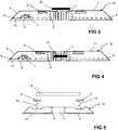
- a liftable roof 12 ( Fig. 3 ).
- the roof 12 may also be provided as a cover with openings and fixed.
- the roof 12 may be overhanging, ie have a larger diameter than the chimney 11. But it could also be capable of lifting in the chimney 11, that is arranged with an inner diameter of the upper end of the fireplace corresponding outer diameter.
- the roof 12 may be provided with a logo and sensor means of the vehicle control for positioning the vehicle resp. the secondary coil 14 above the primary coil 2 included.
- the primary coil 2 could be designed to be capable of lifting in the z-direction as an alternative or in addition to the fan 13 in a further embodiment.
- Lifting and lowering the primary coil 2 can for Example by means of a telescope or scissors jack, the a bellows 15 ( Fig. 5 ). This allows on the one hand a more accurate positioning of the primary coil 2 to the secondary coil 14 and on the other hand due to the "fireplace increase" by the bellows 15 an increase in the chimney effect and thus the cooling of both the primary coil 2 and the secondary coil 14th
- the raised bellows 15 forms a dense, movable curtain or channel which encloses the space created by the lifting or at least the chimney 11.
- a bellows 15 and other elements for forming a curtain, channel or a fireplace extension are conceivable, for example, membranes, preferably elastic, or substantially rigid, extendable from recesses tubes or the like.
- the increase of the primary coil 2 for approaching the secondary coil 14 also contributes to the improvement of the inductive energy transfer between the primary part 1 and the secondary part.
- an adapted parking assistant could be used.
- the charging process can be started, for example, by means of an app and terminated when the maximum storage capacity of the battery is reached.
- the primary part 1 anchored to the ground and a power supply can be secured.
Description
- Die Erfindung betrifft ein Primärteil eines Ladegeräts, insbesondere zur induktiven Übertragung von Energie von einer Primärspule des Primärteils zu einer Sekundärspule eines zumindest teilweise elektrisch betriebenen Fahrzeugs, nach dem Oberbegriff des Anspruchs 1, sowie ein Ladegerät mit einem derartigen Primärteil.
- Für Elektrofahrzeuge, die zumindest teilweise elektromotorisch angetrieben sind, sind Vorrichtungen zur induktiven Übertragung elektrischer Energie von einer Primärspule zu einer Sekundärspule bekannt. Dabei befindet sich die Sekundärspule am oder im Elektrofahrzeug, während die Primärspule ausserhalb des Elektrofahrzeugs angeordnet ist.
- Zum Beispiel ist in der
DE 102011089339 A1 eine solche Vorrichtung offenbart. Die Vorrichtung umfasst ein Grundelement am Boden des Elektrofahrzeugs, eine, dem Grundelement zugeordnete Sekundärspule, die mit einem Speicher für Elektroenergie energetisch koppelbar ist, wobei zumindest ein Teil der Sekundärspule, insbesondere der Spulenkern relativ zum Grundelement bewegbar gelagert ist. - Die Vorrichtung enthält weiterhin ein Stellglied zur relativen Bewegung des Spulenkerns der Sekundärspule zwischen einer unteren und einer oberen Position in z-Richtung mittels Stellmotor oder auch manuell. In der unteren Position befindet sich die Unterkante des Spulenkerns der Sekundärspule nahe zu einer Fahrbahnoberfläche o. a. In der Fahrbahn ist eine bewegbare Primärspule angeordnet. Hierdurch soll ein adaptives Positionieren der Sekundärspule zur Primärspule mit minimiertem Luftspalt zwischen diesen bei einem Ladevorgang erreicht werden. Der Verfahrweg zwischen oberer und unterer Position ist von der Bodenfreiheit des Elektrofahrzeugs bestimmt. Fährt das Elektrofahrzeug, befindet sich der Spulenkern in der oberen Position, innerhalb des Elektrofahrzeugs, was einen Freiraum für das Stellglied erfordert und den nutzbaren Raum mindert.
- Mittels der Vorrichtung soll die Übertragung von Energie bei einem induktiven Ladevorgang verbessert werden. Die Anordnung einer verfahrbaren Sekundärspule erhöht jedoch das Fahrzeuggewicht, was die erzielbare Reichweite reduziert.
- Bei einer weiteren Vorrichtung zur kontaktlosen Leistungsversorgung gemäss
DE 102012020364 A1 ist in einer Ebene eine Vielzahl von Primärspulen vorgesehen, die gruppenweise in einem Gehäuse angeordnet sind und denen Gruppen von Leistungsversorgungseinheitsschaltungen zugeordnet sind. Zur Unterdrückung von der Anregungsfrequenz der Primärspulen ist eine Vielzahl von Einheitscontrollern vorgesehen, die Synchronisationssignale bereitstellen. - Bei einer Ladeschale zum Laden der Akkus von Hörgeräten ist eine, mit einer Steuereinheit verbundene Sekundärspule zum empfangen elektrischer Energie von einer Primärspule vorgesehen, wobei die Primärspule in einer Ladematte angeordnet ist.
- In einer weiteren Vorrichtung zum kontaktlosen Aufladen eines Akkus gemäss
DE 102004039651 A1 wird die zum Aufladen notwendige Energie von einer Energiequelle zu einer Energiesenke über ein Wechselfeld übertragen. Die Feldstärke des Wechselfeldes ist dabei grösser als eine mögliche Feldstärke bei gleichzeitiger Übertragung von Daten und Aufladeenergie. Daten werden nicht im Lademodus übertragen, sondern nur in einem ersten Betriebsmodus, weshalb der Ladevorgang schneller ablaufen soll. - Die
WO 2011/006884 A2 offenbart ein integriertes Primärgehäuse, in welchem in den geneigten Seitenwänden Lüftungsöffnungen vorgesehen sind, über die innen liegende Ventilatoren Kühlluft im Gehäuse umwälzen können, deren Austritt nach oben hin durch das geschlossene Gehäuse verhindert ist. - Eine fix im Boden verbaute Primärstation ist in der
FR 2732169 A1 - Aufgabe der vorliegenden Erfindung ist es somit, den Ladevorgang bei einer induktiven Übertragung von Energie von einer Primärspule des Primärteils zu einer Sekundärspule zu verbessern und die Benutzungssicherheit beim Ladevorgang zu erhöhen.
- Die Aufgabe wird durch die Merkmale der unabhängigen Ansprüche 1 und 14 gelöst. Vorteilhafte Weiterbildungen sind in den Figuren und in den abhängigen Patentansprüchen dargelegt.
- Das erfindungsgemässe Primärteil eines kontaktlosen/induktiven Ladegeräts ist das auf dem Boden einer Garage, einer Tankstelle o. a. m. befindliche Element eines induktiven Ladegeräts, um im Betriebszustand elektrische Energie induktiv in einen Energiespeicher eines zumindest teilweise elektrisch betriebenen Kraftfahrzeugs zu übertragen.
- Das erfindungsgemässe Primärteil umfasst zumindest ein Gehäuseelement mit Primärspule, erforderlicher Ladeelektronik und eine Anschlussmöglichkeit an das Stromnetz, zum Beispiel ein 230V-Stromnetz, wobei die Primärspule an einer bzw. angrenzend an eine Oberseite des Primärteils angeordnet ist.
- Mindestens ein Kanal für Kühlluft geht von einer Eintrittsöffnung im bodennahen Bereich einer Seitenfläche bzw. Umfangsfläche der Bodenplatte des Primärteils aus und weist zumindest einen ansteigenden Teilabschnitt auf.
- Erfindungsgemäss mündet mindestens ein Kanal in mindestens einen das Primärteil von unten nach oben durchsetzenden und nach oben offenen Kamin und steigt in zumindest einem Teilabschnitt bis zur Mündung in den mindestens einen Kamin an.
- Aufgrund der Verlustleistung der Primärspule entsteht Wärme, die zu einer Erwärmung des Primärteils einer induktiven Ladeeinrichtung im Betriebszustand führt. Von an der Bodenplatte vorbeiströmender Luft wird die, durch die Verlustleistung entstandene Wärme besser abgeführt, was einer zu starken, für elektronische bzw. elektrische Elemente unzulässigen Erwärmung entgegenwirkt.
- Vorzugsweise ist der Primärteil mit mindestens zwei, den Primärteil von unten nach oben durchsetzenden Kaminen versehen, was eine weiter verbesserte Wärmeabfuhr gewährleistet.
- Bevorzugt ist der Primärteil in Draufsicht im Wesentlichen rechteckig oder rund ausgebildet und sind die Seitenflächen aus Schrägen gebildet. Diese Formgebung bietet ein sehr gutes Verhältnis von Umfang und Fläche, das sowohl für die Wärmeabfuhr als auch für die induktive Energieübertragung vorteilhaft ist.
- Durch die Merkmale, dass der mindestens eine Kanal nach unten zumindest teilweise offen und nutartig ausgebildet ist, wobei sich vorzugsweise der Nutquerschnitt in Richtung des Kamins verringert, kann die Zufuhr der Kühlluft über die gesamte Länge des Kanals erfolgen, kann der Kanal einfach und rasch gereinigt werden und wird gleichzeitig eine Vergrösserung der für den Wärmeaustausch Primärteil-Kühlluft verfügbaren Oberfläche erzielt.
- Der Luftzutritt wird weiter erleichtert, wenn die Unterseite des Primärteils mit Mitteln zur Herstellung eines Abstandes bzw. Freiraums vom Boden versehen ist.
- Bevorzugt ist der Kamin zentral in z-Richtung gelegen, was eine gute mechanische Stabilität des Primärteils gewährleistet. Der Kamin ist bevorzugt auch mit zum Zentrum des Kamins weisenden Kühlrippen versehen, um damit die für den Wärmeaustausch Primärteil-Kühlluft verfügbare Oberfläche weiter zu vergrössern.
- An jeder Schräge kann mindestens eine Eintrittsöffnung eines, in den Kamin mündenden Kanals vorgesehen sein, um selbst bei Abschottung einer bis drei Seiten des Primärteils eine Kühlwirkung aufrecht zu erhalten.
- Vorzugsweise ist bei einer weiteren erfindungsgemässen Ausführungsform des Primärteil die Primärspule in z-Richtung hubfähig ausgebildet.
- Bei einer derartigen Ausführungsform ist bevorzugt die Primärspule mittels eines Hubmittels mit einem Faltenbalg hubfähig, wobei der angehobene Faltenbalg einen dichten, beweglichen Vorhang bildet, der zumindest einen Kamin umschliesst. Dies verbessert die Kaminwirkung und damit die Luftströmung sowie die Kühlwirkung auf den Primärteil.
- Ebenso kann eine Erhöhung des Luftdurchsatzes zur Verbesserung der Kühlwirkung dadurch erzielt werden, dass ein Lüfter im Kamin eingesetzt ist.
- Um ein Verschmutzen des Kamins und der Kühlkanäle von oben her, mit folglichem Abnehmen der Kühlwirkung, zu verhindern, kann der Kamin an oder nahe der Oberseite des Primärteils mit einem, nicht überstehenden Dach abdeckbar sein.
- Um einerseits eine gute Kühlwirkung und gleichzeitig eine möglichst grosse Fläche für die Primärspule zu gewährleisten, ist die Primärspule ring- oder rechteckförmig den/die Kamin(e) umschliessend im Primärteil angeordnet.
- Dabei kann zur Flächenoptimierung der Primärspule für eine gute Energieübertragung die Primärspule in der Draufsicht einen rechteckigen oder runden Querschnitt aufweisen. Die rechteckige oder speziell quadratische Form der Primärspule wird vorzugsweise mit abgerundeten Eckbereichen ausgeführt sein. Prinzipiell sind auch alle Übergangsformen und gegebenenfalls auch unregelmässige geometrischen Formen möglich, wenn baulich notwendig.
- Die eingangs gestellte Aufgabe wird auch erfindungsgemäss gelöst durch ein Ladegerät zur induktiven Übertragung von Energie, umfassend ein Primärteil nach einem der obigen Absätze. Dieser Primärteilt ist dazu auch mit einer Primärspule versehen, der im Betriebszustand eine Sekundärspule eines zumindest teilweise elektrisch betriebenen Fahrzeugs zuordenbar ist.
- Bevorzugt ist der Primärteil dieses Ladegerätes mit mindestens einem, den Primärteil von unten nach oben durchsetzenden und nach oben offenen Kamin versehen, in den mindestens ein Kanal mündet, dessen Eintrittsöffnung im bodennahen Bereich einer Seitenfläche der Bodenplatte des Primärteils gelegen ist und der zumindest in einem Teilabschnitt bis zur Mündung in den mindestens einen Kamin ansteigt.
- Weitere Vorteile, Merkmale und Einzelheiten der Erfindung ergeben sich aus der nachfolgenden Beschreibung, in der unter Bezugnahme auf die Zeichnungen Ausführungsbeispiele der Erfindung beschrieben sind. Dabei können die in den Ansprüchen und in der Beschreibung erwähnten Merkmale jeweils einzeln für sich oder in beliebiger Kombination erfindungswesentlich sein.
- Die Bezugszeichenliste ist Bestandteil der Offenbarung. Die Figuren werden zusammenhängend und übergreifend beschrieben. Gleiche Bezugszeichen bedeuten gleiche Bauteile, Bezugszeichen mit unterschiedlichen Indices geben funktionsgleiche oder ähnliche Bauteile an.
- Es zeigen dabei:
- Fig. 1
- ein erfindungsgemässes Primärteil in Seitenansicht;
- Fig. 2
- das Primärteil nach
Fig. 1 von unten gesehen; - Fig. 3
- das Primärteil nach
Fig. 1 mit Dach; - Fig. 4
- das Primärteil nach
Fig. 1 mit zusätzlichem Lüfter; - Fig. 5
- das Primärteil nach
Fig. 1 mit Primärspulenhub zur Kaminerhöhung; - Fig. 6
- ein erfindungsgemässes Primärteil in einer weiteren, bevorzugten Ausführungsform.
- Die
Fig. 1, 2 oder6 zeigen ein überfahrfestes Primärteil 1 eines Ladegeräts zur induktiven Übertragung von Energie von einer im Beispiel ringförmigen Primärspule 2 zu einer Sekundärspule 14 am Fahrzeugboden und von da in eine Batterie eines zumindest teilweise elektrisch betriebenen, nicht dargestellten Fahrzeugs. Die Primärspule 2 ist in einer Bodenplatte 18 (Gehäuseelement) des Primärteils 1 (GPM) angeordnet. Die Fig. 7 zeigt eine bevorzugte Ausführungsform, dieFiguren 1 oder 2 eine vereinfachte Darstellung. - Die Höhe des Primärteils 1 soll möglichst gering sein und beträgt im Beispiel ca. 6cm. Das Primärteil besteht bevorzugt aus einem leichtmetallischen Werkstoff oder einem wärmebeständigen und mechanisch belastbaren Kunststoff.
- Die Primärspule 2 ist bevorzugt quadratisch ausgebildet und könnte auch rechteckförmig ausgebildet sein. Dabei sind die Eckbereiche typischerweise abgerundet. Auch im Wesentlichen runde Spulengeometrien oder wenn notwendig unregelmässige geometrischen Formen sind möglich.
- Das Primärteil 1 entspricht in seiner Grundform einem flachen Kegel- oder Pyramidenstumpf mit Schrägen 4 als Seiten- oder Umfangsflächen und somit einer Unterseite 6, deren Fläche grösser ist als die Fläche der Oberseite 7. Flächenübergänge können gerundet oder "verschliffen" sein. Ggf. können die Seiten- oder Umfangsflächen 4 auch senkrecht zur Unter- und Oberseite 6, 7 gelegen sein.
- Die Primärspule 2 ist bevorzugt im Innern der Bodenplatte 18, nahe der Oberseite 7, oder auch in einer Aussparung an der Oberseite 7 des Primärteils 1 angeordnet und ist mit einer Ladeelektronik 3 verbunden.
- Die Primärspule 2 kann bündig mit der Oberseite 7 abschliessen oder auch etwas ins Innere des Primärteils 1 versetzt sein. Die Primärspule 2 weist, in der Draufsicht senkrecht auf die Oberseite 7 des Gehäuseelements 18, im Beispiel einen rechteckigen Querschnitt auf, doch ist ebenso ein elliptischer oder runder Querschnitt möglich.
- Das Primärteil 1 ist in z-Richtung, senkrecht zur Bodenebene, mit zumindest einem Kamin 11, gegebenenfalls mit mehreren, voneinander beabstandeten Kaminen 11, mit bevorzugt kreisrundem Querschnitt versehen. In diese Kamine 11 münden Kanäle 10 mit ihren Austrittsöffnungen 9. Der Querschnitt der Kamine 11 kann auch oval, schlitzförmig oder unregelmässig geformt sein.
- Die Kanäle 10 beginnen an Eintrittsöffnungen 8 bodennah an den Schrägen 4 oder anderen Seitenflächen und weisen zum Beispiel einen runden Querschnitt auf. An allen Seitenflächen bzw. Schrägen 4 ist mindestens eine Eintrittsöffnung 8 für einen Kanal 10 vorgesehen. Bevorzugt sind, wie dargestellt, jedoch mehrere Kanäle 10 pro Seitenfläche 4 vorgesehen.
- Austrittsöffnungen 9 weiterer Kanäle 10 könnten aber auch an anderen Stellen der Oberseite 7, bevorzugt nahe zur Primärspule 2, gelegen sein. Damit ist eine noch unmittelbarere Kühlung speziell dieser Primärspule 2 möglich.
- Die Kanäle 10 weisen zumindest in einem Teilbereich, bevorzugt über ihren gesamten Verlauf einen positiven, gegebenenfalls stetigen, Anstiegswinkel von der Eintrittsöffnung 8 bis zur Austrittsöffnung 9 auf. Oftmals sind jedoch im Wesentlichen horizontal verlaufende Abschnitte 10 vorgesehen, die in im Wesentlichen vertikale Austrittsöffnungen 9 übergehen, wie in den
Fig. 1 bis 4 dargestellt. - Die Kamine 11 sind so angeordnet, dass die Ladeelektronik und/oder eine mögliche Anordnung von Noppen 19 (siehe
Fig. 6 ) an der Unterseite 6 des Primärteils 1 bzw. der Bodenplatte 18 dadurch nicht beeinträchtigt wird, insbesondere in Bezug auf die mechanische Festigkeit der Bodenplatte 18. Die Kanäle 10 bzw. Kanalnuten sind auf alle Kamine 11 gerichtet. Das zwischen den Kaminen 11 verbleibende Material der Bodenplatte 18 wirkt wie Stützpfeiler. Wie inFig. 6 beispielhaft dargestellt können die Kamine 11 auch Bestandteil durchbohrter, in der Bodenplatte 18 vorgesehener Stützpfeiler sein. - Durch die Noppen 19, mit welchen allein die Bodenplatte 18 auf dem Untergrund aufliegen und Kontakt machen kann, vergrössert sich der verfügbare Raum für die strömende Luft im Bodenbereich und damit auch der für die Kühlung nutzbare Luftdurchsatz.
- Die Kamine 11 können "formgebend" in Mustern angeordnet und auch von unten resp. innen beleuchtet sein.
- Die Kanäle 10 können bevorzugt nach unten zumindest teilweise offen und somit nutförmig ausgebildet sein, so dass kühle Luft am Boden unter dem Primärteil 1 ansteigend zum Kamin 11 strömen kann. Durch geeignete Dimensionierung (nicht dargestellt) der Nut-Zwischenräume kann die Luftmenge für eine kontinuierliche und effiziente Kühlung des Primärteils 1 resp. der Spulen 2 gesteuert werden. Der Querschnitt der Kanäle 10 verringert sich im dargestellten Beispiel in Richtung zu den Kaminen 11 hin, was aber nicht zwingend vorgesehen sein muss.
- In dieser Ausgestaltung können die Kanäle 10 zum Beispiel einfach nutförmig in die Unterseite 6 des Primärteils 1 gefräst werden und sind aufgrund ihrer offenen Ausführung auch problemlos zu reinigen.
- Die sich zwischen den Kanalnuten bildenden Rippen können als zur Verstärkung der Kühlleistung als Kühlrippen 17 bis in die Kamine 11 reichen.
- Das Primärteil 1 kann ggf. in z-Richtung, senkrecht zur Bodenebene, mit nur einem zentral gelegenen Kamin 11 versehen sein.
- Zur Herstellung eines Betriebszustandes zur induktiven Übertragung von elektrischer Energie wird eine Sekundärspule 14 in einem Sekundärteil (CPM) des Ladegeräts über der Primärspule 2 des Primärteils 1 positioniert.
- Der Abstand in z-Richtung zwischen Primärspule 2 und Sekundärspule 14 sollte möglichst gering sein.
- Da die Lufttemperatur am Boden im Normalfall geringer ist als an der Oberseite 7 des Primärteils 1 wird die Luft durch die Eintrittsöffnungen 8 angesaugt, durchströmt die Kanäle 10 und verlässt diese über die Austrittsöffnungen 9. Die durch den Kamin 11 abgeführte Luft kühlt beim weiteren Aufsteigen, beispielsweise zum Sekundärteil des induktiven Ladesystems, ab und kann somit im Betriebszustand des Ladegeräts auch kühlend auf den Sekundärteil und dessen Sekundärspule 14 wirken. Eine Kühlwirkung wird auch durch die erhöhte Geschwindigkeit der um den Sekundärteil strömenden Luft erzielt.
- Luft kann auch an den Schrägen 4 entlang nach oben strömen und die Kühlwirkung erhöhen.
- Zudem können die Kamine 11 und die Kühlrippen 17 auch ohne Luftströmung durch die Kanäle 10 zur Kühlung der Primärspule 2 resp. des Primärteils 1 beitragen.
- Aufgrund der geringen Bauhöhe des Primärteils 1 ist der Kamineffekt begrenzt, so dass die Kühlleistung bei Bedarf durch weitere Massnahmen erhöht werden kann.
- Es ist möglich, einen Lüfter 13 (
Fig. 4 ) im Kamin 11 anzuordnen, der einen, gegenüber der natürlichen Konvektionsströmung grösseren Luftstrom erzeugen kann. Die Saugleistung des Lüfters 13 kann an die erzeugte Verlustleistung der Primärspule 2 und/oder der Ladeelektronik 3 angepasst sein. - Der Lüfter 13 soll medienbeständig und verschmutzungsresistent sein. Der Lüfter 13 soll auch eine Umkehrung der Luftstromrichtung ermöglichen, um die Kanäle 10, Lufteintrittsöffnungen 8 und Kamine 11 von Schmutz zu reinigen (Ausblasfunktion).
- Weiterhin könnten die Öffnungen 8, 9 der Kanäle 10 und die Öffnung der Kamine 11 mit Schutzgittern oder dergleichen versehen werden.
- Um eine Verschmutzung der Kamine 11 zu vermeiden oder zu verringern, kann dieser auch an der Oberseite 7 über oder in der Öffnung des Kamins 11 mit einem hubfähigen Dach 12 abgedeckt sein (
Fig. 3 ). Das Dach 12 kann auch als Abdeckhaube mit Öffnungen versehen und fest angeordnet sein. Das Dach 12 kann überstehend sein, d. h. einen grösseren Durchmesser als der Kamin 11 aufweisen. Es könnte aber auch hubfähig im Kamin 11, d.h. mit einem dem Innendurchmesser des oberen Kaminendes entsprechendem Aussendurchmesser, angeordnet sein. - Das Dach 12 kann mit einem Logo versehen sein und auch Sensormittel der Fahrzeugsteuerung zur Positionierung des Fahrzeugs resp. der Sekundärspule 14 über der Primärspule 2 enthalten.
- Zur Vergrösserung der Kühlleistung könnte alternativ oder in Ergänzung zum Lüfter 13 in einer weiteren Ausführungsform die Primärspule 2 in z-Richtung hubfähig ausgebildet sein. Heben und Senken der Primärspule 2 kann zum Beispiel mittels eines Teleskops oder Scherenhebers erfolgen, der einen Faltenbalg 15 (
Fig. 5 ) betätigt. Dies ermöglicht einerseits eine genauere Positionierung der Primärspule 2 zur Sekundärspule 14 und andererseits infolge der "Kaminerhöhung" durch den Faltenbalg 15 eine Erhöhung der Kaminwirkung und somit der Kühlung sowohl der Primärspule 2 als auch der Sekundärspule 14. - Der angehobene Faltenbalg 15 bildet einen dichten, beweglichen Vorhang oder Kanal, der den durch das Anheben entstehenden Freiraum oder zumindest den Kamin 11 umschliesst. Anstelle eines Faltenbalges 15 sind auch andere Element zur Bildung eines Vorhanges, Kanals oder einer Kaminverlängerung denkbar, beispielsweise Membranen, vorzugsweise elastisch, oder im Wesentlichen starre, aus Ausnehmungen ausfahrbare Röhren od.dgl. Die Anhebung der Primärspule 2 zur Annäherung an die Sekundärspule 14 trägt auch zur Verbesserung der induktiven Energieübertragung zwischen Primärteil 1 und Sekundärteil bei.
- Weitere mögliche Ausführungsformen umfassen durch den Boden des Gehäuses, d.h. der Bodenplatte 18, nach unten abgeschlossene Kanäle 10. Diese Konstruktionsarten entsprechen dann einer Platte mit Zwangs-Unterlüftung oder mit einem liegenden Kamin 11 mit Zwangsbelüftung.
- Zur zielgenauen Positionierung der Sekundärspule 14 zur Primärspule 2 könnte zum Beispiel ein adaptierter Parkassistent verwendet werden.
- Der Ladevorgang kann zum Beispiel mittels einer App gestartet und bei Erreichung des maximalen Speichervermögens der Batterie beendet werden.
- Mittels nicht dargestellter, fachüblicher Mittel kann das Primärteil 1 am Boden verankert und eine Stromversorgung gesichert werden.
-
- 1
- Primärteil
- 2
- Primärspule
- 3
- Ladeelektronik
- 4
- Schräge/Seitenfläche
- 6
- Unterseite
- 7
- Oberseite
- 8
- Eintrittsöffnung
- 9
- Austrittsöffnung
- 10
- Kanal
- 11
- Kamin
- 12
- Dach
- 13
- Lüfter
- 14
- Sekundärspule
- 15
- Faltenbalg
- 17
- Kühlrippe
- 18
- Bodenplatte
- 19
- Noppen
- z
- Achse/Richtung
Claims (15)
- Primärteil für ein Ladegerät, mit einer Unterseite (6) und einer Oberseite (7) sowie den Primärteil (1) begrenzenden Seitenflächen, und mit einer Primärspule (2) zur induktiven Übertragung von Energie zu einer Sekundärspule (14) eines zumindest teilweise elektrisch betriebenen Fahrzeugs, wobei die Primärspule (2) mit einer Ladeelektronik (3) verbunden und an der oder angrenzend an die Oberseite (7) des Primärteils (1) angeordnet ist, wobei mindestens ein Kanal (10) von einer Eintrittsöffnung (8) im bodennahen Bereich einer der Seitenflächen des als Bodenplatte ausgebildeten Primärteils (1) ausgeht und zumindest einen ansteigenden Teilabschnitt aufweist, dadurch gekennzeichnet, dass der Kanal (10) in mindestens einen das Primärteil (1) von unten nach oben durchsetzenden und nach oben hin offenen Kamin (11) mündet und in zumindest einem Teilabschnitt bis zur Mündung in den mindestens einen Kamin (11) ansteigt.
- Primärteil nach Anspruch 1, dadurch gekennzeichnet, dass es mit mindestens zwei, den Primärteil (1) von unten nach oben durchsetzenden Kaminen (11) versehen ist.
- Primärteil nach Anspruch 1 oder 2, dadurch gekennzeichnet, dass es in Draufsicht im Wesentlichen rechteckig oder rund ausgebildet ist und dass die Seitenflächen aus Schrägen (4) gebildet sind.
- Primärteil nach einem der Ansprüche 1 bis 3, dadurch gekennzeichnet, dass der mindestens eine Kanal (10) nach unten zumindest teilweise offen und nutartig ausgebildet ist, wobei sich vorzugsweise der Nutquerschnitt in Richtung des Kamins (11) verringert.
- Primärteil nach einem der Ansprüche 1 bis 3, dadurch gekennzeichnet, dass die Unterseite (6) des Primärteils (1) mit Mitteln zur Herstellung eines Abstandes bzw. Freiraums vom Boden versehen ist.
- Primärteil nach einem der Ansprüche 1 bis 5, dadurch gekennzeichnet, dass der Kamin (11) zentral in z-Richtung gelegen und mit zum Zentrum des Kamins (11) weisenden Kühlrippen (17) versehen ist.
- Primärteil nach einem der Ansprüche 1 bis 6, dadurch gekennzeichnet, dass an jeder Schräge (4) mindestens eine Eintrittsöffnung (8) eines, in den Kamin (11) mündenden Kanals (10) vorgesehen ist.
- Primärteil nach einem der Ansprüche 1 bis 7, dadurch gekennzeichnet, dass die Primärspule (2) in z-Richtung hubfähig ausgebildet ist.
- Primärteil nach Anspruch 8, dadurch gekennzeichnet, dass die Primärspule (2) mittels eines Hubmittels mit einem Faltenbalg (15) hubfähig ist, wobei der angehobene Faltenbalg (15) einen dichten, beweglichen Vorhang bildet, der zumindest einen Kamin (11) umschliesst.
- Primärteil nach einem der Ansprüche 1 bis 9, dadurch gekennzeichnet, dass ein Lüfter (13, 16) im Kamin (11) eingesetzt ist.
- Primärteil nach einem der Ansprüche 1 bis 10, dadurch gekennzeichnet, dass der Kamin (11) an oder nahe der Oberseite (7) des Primärteils (1) mit einem, nicht überstehenden Dach (12) abdeckbar ist.
- Primärteil nach einem der Ansprüche 1 bis 11, dadurch gekennzeichnet, dass die Primärspule (2) ring- oder rechteckförmig den/die Kamin(e) (11) umschliessend im Primärteil (1) angeordnet ist.
- Primärteil nach einem der Ansprüche 1 bis 12, dadurch gekennzeichnet, dass die Primärspule (2) einen rechteckigen oder gerundeten Querschnitt aufweist.
- Ladegerät zur induktiven Übertragung von Energie, umfassend ein Primärteil (1) nach einem der Ansprüche 1 bis 13, mit einer Primärspule (2), der im Betriebszustand eine Sekundärspule (14) eines zumindest teilweise elektrisch betriebenen Fahrzeugs zuordenbar ist.
- Ladegerät nach Anspruch 14, dadurch gekennzeichnet, dass das Primärteil (1) mit mindestens einem, den Primärteil (1) von unten nach oben durchsetzenden und nach oben offenen Kamin (11) versehen ist, in den mindestens ein Kanal (10) mündet, dessen Eintrittsöffnung (8) im bodennahen Bereich einer Seitenfläche der Bodenplatte (18) des Primärteils (1) gelegen ist und der zumindest in einem Teilabschnitt bis zur Mündung in den mindestens einen Kamin (11) ansteigt.
Priority Applications (1)
| Application Number | Priority Date | Filing Date | Title |
|---|---|---|---|
| EP14176348.2A EP2965941B1 (de) | 2014-07-09 | 2014-07-09 | Primärteil für ein induktives Ladegerät |
Applications Claiming Priority (1)
| Application Number | Priority Date | Filing Date | Title |
|---|---|---|---|
| EP14176348.2A EP2965941B1 (de) | 2014-07-09 | 2014-07-09 | Primärteil für ein induktives Ladegerät |
Publications (2)
| Publication Number | Publication Date |
|---|---|
| EP2965941A1 EP2965941A1 (de) | 2016-01-13 |
| EP2965941B1 true EP2965941B1 (de) | 2017-09-13 |
Family
ID=51162553
Family Applications (1)
| Application Number | Title | Priority Date | Filing Date |
|---|---|---|---|
| EP14176348.2A Active EP2965941B1 (de) | 2014-07-09 | 2014-07-09 | Primärteil für ein induktives Ladegerät |
Country Status (1)
| Country | Link |
|---|---|
| EP (1) | EP2965941B1 (de) |
Families Citing this family (5)
| Publication number | Priority date | Publication date | Assignee | Title |
|---|---|---|---|---|
| FR3070097B1 (fr) * | 2017-08-09 | 2021-05-07 | Continental Automotive France | Dispositif de charge par induction a evacuation de chaleur interne |
| DE102018009488A1 (de) | 2018-12-03 | 2019-06-27 | Daimler Ag | Abschlrmvorrlchtung und Verfahren zum Abschlrmen oder Entfernen elnes Fremdobjekts |
| EP3913764A1 (de) | 2020-05-20 | 2021-11-24 | Nokia Technologies Oy | Ladevorrichtung |
| DE102022202925A1 (de) * | 2022-03-24 | 2023-09-28 | Mahle International Gmbh | Stationäre Induktionsladeeinrichtung |
| WO2024052186A1 (en) * | 2022-09-08 | 2024-03-14 | Brusa Elektronik Ag | Vehicle charging device with optimized cooling |
Family Cites Families (8)
| Publication number | Priority date | Publication date | Assignee | Title |
|---|---|---|---|---|
| DE4236286A1 (de) * | 1992-10-28 | 1994-05-05 | Daimler Benz Ag | Verfahren und Anordnung zum automatischen berührungslosen Laden |
| FR2732169B1 (fr) * | 1995-03-24 | 1997-05-09 | Peugeot | Dispositif pour recharger les batteries d'accumulateurs d'un vehicule electrique |
| DE102004039651A1 (de) | 2004-08-16 | 2006-03-09 | Giesecke & Devrient Gmbh | Gesteuertes kontaktloses Aufladen eines Akkumulators |
| RU2506181C2 (ru) * | 2009-07-15 | 2014-02-10 | Кондуктикс-Вампфлер Гмбх | Система для индуктивной зарядки транспортных средств, снабженных электронной системой позиционирования |
| DE102011108546A1 (de) * | 2011-07-26 | 2013-01-31 | Daimler Ag | Vorrichtung und Verfahren zum Laden eines Energiespeichers eines Fahrzeuges |
| DE102011118397A1 (de) * | 2011-11-12 | 2012-05-16 | Daimler Ag | Vorrichtung zum kabellosen Laden eines elektrischen Energiespeichers eines elektrisch angetriebenen Kraftfahrzeugs |
| DE102011089339A1 (de) | 2011-12-21 | 2013-06-27 | Continental Automotive Gmbh | Induktives Übertragen von Energie von einer Primärspule zu einer Sekundärspule eines elektromobilen Kraftfahrzeugs |
| DE102012020364A1 (de) | 2012-10-17 | 2014-04-17 | Panasonic Corporation | Verfahren zum Anregen von Primärspulen in einer kontaktlosen Leistungsversorgungsvorrichtung und kontaktlose Leistungsversorgungsvorrichtung |
-
2014
- 2014-07-09 EP EP14176348.2A patent/EP2965941B1/de active Active
Non-Patent Citations (1)
| Title |
|---|
| None * |
Also Published As
| Publication number | Publication date |
|---|---|
| EP2965941A1 (de) | 2016-01-13 |
Similar Documents
| Publication | Publication Date | Title |
|---|---|---|
| EP2965941B1 (de) | Primärteil für ein induktives Ladegerät | |
| EP3125355B1 (de) | Vorrichtung für ein fahrzeug, insbesondere für ein nutzfahrzeug | |
| EP3065152A1 (de) | Primärteil eines induktiven ladegeräts | |
| DE102007005367A1 (de) | Fahrzeug-Stromversorgungsvorrichtung | |
| EP3717307A1 (de) | Ladevorrichtung zum drahtlosen laden eines mobilen endgerätes | |
| DE202015100764U1 (de) | Stapelbare Abschlussplatten für Kühleröffnungen | |
| EP2987670B1 (de) | Vorrichtung zur abstimmung eines luftdurchsatzes | |
| DE102011090066A1 (de) | Lüftermodul | |
| DE102020215074A1 (de) | Elektromagnetische Induktionsladeeinrichtung | |
| EP2852795B1 (de) | Vorrichtung zum elektrischen aufheizen | |
| DE102006025535A1 (de) | Vorrichtung zur Kühlung elektrischer Elemente | |
| EP3600928A1 (de) | Elektrisches heizgerät | |
| EP2993337B1 (de) | Flugzeugtriebwerk mit mindestens einer vorrichtung zur entnahme von zapfluft | |
| EP3297089B1 (de) | Flurförderzeug mit einer traktionsbatterie | |
| DE102019109400A1 (de) | Ladevorrichtung für einen elektrischen Ladevorgang eines Mobilgeräts in einem Fahrzeug | |
| EP2088012B1 (de) | Ladegerät für eine Batterie eines Fahrzeugs | |
| DE102019127928B3 (de) | Ladevorrichtung für einen elektrischen Ladevorgang eines Mobilgeräts in einem Fahrzeug | |
| DE102015106093A1 (de) | Klimaanlage für Fahrzeuge | |
| EP3216330A1 (de) | Wechselrichter und verfahren zum kühlen eines wechselrichters | |
| WO2019137748A1 (de) | Steuereinrichtung zum ansteuern eines e-motors | |
| DE102018202131A1 (de) | Komponente für ein Kraftfahrzeug und Kraftfahrzeug | |
| DE102021113817A1 (de) | Kugelventil mit mehrwinkliger dichtung für kühlmittelregler | |
| DE102020134363B4 (de) | Ladeeinrichtung | |
| DE102019132815A1 (de) | Vorrichtung zur drahtlosen Übertragung elektrischer Energie | |
| EP0639744A2 (de) | Luftverteiler |
Legal Events
| Date | Code | Title | Description |
|---|---|---|---|
| PUAI | Public reference made under article 153(3) epc to a published international application that has entered the european phase |
Free format text: ORIGINAL CODE: 0009012 |
|
| AK | Designated contracting states |
Kind code of ref document: A1 Designated state(s): AL AT BE BG CH CY CZ DE DK EE ES FI FR GB GR HR HU IE IS IT LI LT LU LV MC MK MT NL NO PL PT RO RS SE SI SK SM TR |
|
| AX | Request for extension of the european patent |
Extension state: BA ME |
|
| 17P | Request for examination filed |
Effective date: 20160707 |
|
| RBV | Designated contracting states (corrected) |
Designated state(s): AL AT BE BG CH CY CZ DE DK EE ES FI FR GB GR HR HU IE IS IT LI LT LU LV MC MK MT NL NO PL PT RO RS SE SI SK SM TR |
|
| GRAP | Despatch of communication of intention to grant a patent |
Free format text: ORIGINAL CODE: EPIDOSNIGR1 |
|
| STAA | Information on the status of an ep patent application or granted ep patent |
Free format text: STATUS: GRANT OF PATENT IS INTENDED |
|
| INTG | Intention to grant announced |
Effective date: 20170411 |
|
| GRAS | Grant fee paid |
Free format text: ORIGINAL CODE: EPIDOSNIGR3 |
|
| GRAA | (expected) grant |
Free format text: ORIGINAL CODE: 0009210 |
|
| STAA | Information on the status of an ep patent application or granted ep patent |
Free format text: STATUS: THE PATENT HAS BEEN GRANTED |
|
| AK | Designated contracting states |
Kind code of ref document: B1 Designated state(s): AL AT BE BG CH CY CZ DE DK EE ES FI FR GB GR HR HU IE IS IT LI LT LU LV MC MK MT NL NO PL PT RO RS SE SI SK SM TR |
|
| REG | Reference to a national code |
Ref country code: GB Ref legal event code: FG4D Free format text: NOT ENGLISH |
|
| REG | Reference to a national code |
Ref country code: CH Ref legal event code: EP |
|
| REG | Reference to a national code |
Ref country code: IE Ref legal event code: FG4D Free format text: LANGUAGE OF EP DOCUMENT: GERMAN |
|
| REG | Reference to a national code |
Ref country code: AT Ref legal event code: REF Ref document number: 927793 Country of ref document: AT Kind code of ref document: T Effective date: 20171015 |
|
| REG | Reference to a national code |
Ref country code: DE Ref legal event code: R096 Ref document number: 502014005412 Country of ref document: DE |
|
| REG | Reference to a national code |
Ref country code: NL Ref legal event code: MP Effective date: 20170913 |
|
| REG | Reference to a national code |
Ref country code: LT Ref legal event code: MG4D |
|
| PG25 | Lapsed in a contracting state [announced via postgrant information from national office to epo] |
Ref country code: LT Free format text: LAPSE BECAUSE OF FAILURE TO SUBMIT A TRANSLATION OF THE DESCRIPTION OR TO PAY THE FEE WITHIN THE PRESCRIBED TIME-LIMIT Effective date: 20170913 Ref country code: NO Free format text: LAPSE BECAUSE OF FAILURE TO SUBMIT A TRANSLATION OF THE DESCRIPTION OR TO PAY THE FEE WITHIN THE PRESCRIBED TIME-LIMIT Effective date: 20171213 Ref country code: HR Free format text: LAPSE BECAUSE OF FAILURE TO SUBMIT A TRANSLATION OF THE DESCRIPTION OR TO PAY THE FEE WITHIN THE PRESCRIBED TIME-LIMIT Effective date: 20170913 Ref country code: SE Free format text: LAPSE BECAUSE OF FAILURE TO SUBMIT A TRANSLATION OF THE DESCRIPTION OR TO PAY THE FEE WITHIN THE PRESCRIBED TIME-LIMIT Effective date: 20170913 Ref country code: FI Free format text: LAPSE BECAUSE OF FAILURE TO SUBMIT A TRANSLATION OF THE DESCRIPTION OR TO PAY THE FEE WITHIN THE PRESCRIBED TIME-LIMIT Effective date: 20170913 |
|
| PG25 | Lapsed in a contracting state [announced via postgrant information from national office to epo] |
Ref country code: BG Free format text: LAPSE BECAUSE OF FAILURE TO SUBMIT A TRANSLATION OF THE DESCRIPTION OR TO PAY THE FEE WITHIN THE PRESCRIBED TIME-LIMIT Effective date: 20171213 Ref country code: LV Free format text: LAPSE BECAUSE OF FAILURE TO SUBMIT A TRANSLATION OF THE DESCRIPTION OR TO PAY THE FEE WITHIN THE PRESCRIBED TIME-LIMIT Effective date: 20170913 Ref country code: RS Free format text: LAPSE BECAUSE OF FAILURE TO SUBMIT A TRANSLATION OF THE DESCRIPTION OR TO PAY THE FEE WITHIN THE PRESCRIBED TIME-LIMIT Effective date: 20170913 Ref country code: ES Free format text: LAPSE BECAUSE OF FAILURE TO SUBMIT A TRANSLATION OF THE DESCRIPTION OR TO PAY THE FEE WITHIN THE PRESCRIBED TIME-LIMIT Effective date: 20170913 Ref country code: GR Free format text: LAPSE BECAUSE OF FAILURE TO SUBMIT A TRANSLATION OF THE DESCRIPTION OR TO PAY THE FEE WITHIN THE PRESCRIBED TIME-LIMIT Effective date: 20171214 |
|
| PG25 | Lapsed in a contracting state [announced via postgrant information from national office to epo] |
Ref country code: NL Free format text: LAPSE BECAUSE OF FAILURE TO SUBMIT A TRANSLATION OF THE DESCRIPTION OR TO PAY THE FEE WITHIN THE PRESCRIBED TIME-LIMIT Effective date: 20170913 |
|
| PG25 | Lapsed in a contracting state [announced via postgrant information from national office to epo] |
Ref country code: RO Free format text: LAPSE BECAUSE OF FAILURE TO SUBMIT A TRANSLATION OF THE DESCRIPTION OR TO PAY THE FEE WITHIN THE PRESCRIBED TIME-LIMIT Effective date: 20170913 Ref country code: CZ Free format text: LAPSE BECAUSE OF FAILURE TO SUBMIT A TRANSLATION OF THE DESCRIPTION OR TO PAY THE FEE WITHIN THE PRESCRIBED TIME-LIMIT Effective date: 20170913 Ref country code: PL Free format text: LAPSE BECAUSE OF FAILURE TO SUBMIT A TRANSLATION OF THE DESCRIPTION OR TO PAY THE FEE WITHIN THE PRESCRIBED TIME-LIMIT Effective date: 20170913 |
|
| PG25 | Lapsed in a contracting state [announced via postgrant information from national office to epo] |
Ref country code: SM Free format text: LAPSE BECAUSE OF FAILURE TO SUBMIT A TRANSLATION OF THE DESCRIPTION OR TO PAY THE FEE WITHIN THE PRESCRIBED TIME-LIMIT Effective date: 20170913 Ref country code: IS Free format text: LAPSE BECAUSE OF FAILURE TO SUBMIT A TRANSLATION OF THE DESCRIPTION OR TO PAY THE FEE WITHIN THE PRESCRIBED TIME-LIMIT Effective date: 20180113 Ref country code: IT Free format text: LAPSE BECAUSE OF FAILURE TO SUBMIT A TRANSLATION OF THE DESCRIPTION OR TO PAY THE FEE WITHIN THE PRESCRIBED TIME-LIMIT Effective date: 20170913 Ref country code: SK Free format text: LAPSE BECAUSE OF FAILURE TO SUBMIT A TRANSLATION OF THE DESCRIPTION OR TO PAY THE FEE WITHIN THE PRESCRIBED TIME-LIMIT Effective date: 20170913 Ref country code: EE Free format text: LAPSE BECAUSE OF FAILURE TO SUBMIT A TRANSLATION OF THE DESCRIPTION OR TO PAY THE FEE WITHIN THE PRESCRIBED TIME-LIMIT Effective date: 20170913 |
|
| REG | Reference to a national code |
Ref country code: DE Ref legal event code: R097 Ref document number: 502014005412 Country of ref document: DE |
|
| PLBE | No opposition filed within time limit |
Free format text: ORIGINAL CODE: 0009261 |
|
| STAA | Information on the status of an ep patent application or granted ep patent |
Free format text: STATUS: NO OPPOSITION FILED WITHIN TIME LIMIT |
|
| REG | Reference to a national code |
Ref country code: FR Ref legal event code: PLFP Year of fee payment: 5 |
|
| PG25 | Lapsed in a contracting state [announced via postgrant information from national office to epo] |
Ref country code: DK Free format text: LAPSE BECAUSE OF FAILURE TO SUBMIT A TRANSLATION OF THE DESCRIPTION OR TO PAY THE FEE WITHIN THE PRESCRIBED TIME-LIMIT Effective date: 20170913 |
|
| 26N | No opposition filed |
Effective date: 20180614 |
|
| PG25 | Lapsed in a contracting state [announced via postgrant information from national office to epo] |
Ref country code: MT Free format text: LAPSE BECAUSE OF FAILURE TO SUBMIT A TRANSLATION OF THE DESCRIPTION OR TO PAY THE FEE WITHIN THE PRESCRIBED TIME-LIMIT Effective date: 20170913 |
|
| PG25 | Lapsed in a contracting state [announced via postgrant information from national office to epo] |
Ref country code: SI Free format text: LAPSE BECAUSE OF FAILURE TO SUBMIT A TRANSLATION OF THE DESCRIPTION OR TO PAY THE FEE WITHIN THE PRESCRIBED TIME-LIMIT Effective date: 20170913 |
|
| REG | Reference to a national code |
Ref country code: DE Ref legal event code: R079 Ref document number: 502014005412 Country of ref document: DE Free format text: PREVIOUS MAIN CLASS: B60L0011180000 Ipc: B60L0050500000 |
|
| REG | Reference to a national code |
Ref country code: CH Ref legal event code: PL |
|
| PG25 | Lapsed in a contracting state [announced via postgrant information from national office to epo] |
Ref country code: MC Free format text: LAPSE BECAUSE OF FAILURE TO SUBMIT A TRANSLATION OF THE DESCRIPTION OR TO PAY THE FEE WITHIN THE PRESCRIBED TIME-LIMIT Effective date: 20170913 Ref country code: LU Free format text: LAPSE BECAUSE OF NON-PAYMENT OF DUE FEES Effective date: 20180709 |
|
| REG | Reference to a national code |
Ref country code: BE Ref legal event code: MM Effective date: 20180731 |
|
| REG | Reference to a national code |
Ref country code: IE Ref legal event code: MM4A |
|
| PG25 | Lapsed in a contracting state [announced via postgrant information from national office to epo] |
Ref country code: LI Free format text: LAPSE BECAUSE OF NON-PAYMENT OF DUE FEES Effective date: 20180731 Ref country code: IE Free format text: LAPSE BECAUSE OF NON-PAYMENT OF DUE FEES Effective date: 20180709 Ref country code: CH Free format text: LAPSE BECAUSE OF NON-PAYMENT OF DUE FEES Effective date: 20180731 |
|
| PG25 | Lapsed in a contracting state [announced via postgrant information from national office to epo] |
Ref country code: BE Free format text: LAPSE BECAUSE OF NON-PAYMENT OF DUE FEES Effective date: 20180731 |
|
| PG25 | Lapsed in a contracting state [announced via postgrant information from national office to epo] |
Ref country code: TR Free format text: LAPSE BECAUSE OF FAILURE TO SUBMIT A TRANSLATION OF THE DESCRIPTION OR TO PAY THE FEE WITHIN THE PRESCRIBED TIME-LIMIT Effective date: 20170913 |
|
| PG25 | Lapsed in a contracting state [announced via postgrant information from national office to epo] |
Ref country code: PT Free format text: LAPSE BECAUSE OF FAILURE TO SUBMIT A TRANSLATION OF THE DESCRIPTION OR TO PAY THE FEE WITHIN THE PRESCRIBED TIME-LIMIT Effective date: 20170913 |
|
| PG25 | Lapsed in a contracting state [announced via postgrant information from national office to epo] |
Ref country code: HU Free format text: LAPSE BECAUSE OF FAILURE TO SUBMIT A TRANSLATION OF THE DESCRIPTION OR TO PAY THE FEE WITHIN THE PRESCRIBED TIME-LIMIT; INVALID AB INITIO Effective date: 20140709 Ref country code: CY Free format text: LAPSE BECAUSE OF FAILURE TO SUBMIT A TRANSLATION OF THE DESCRIPTION OR TO PAY THE FEE WITHIN THE PRESCRIBED TIME-LIMIT Effective date: 20170913 Ref country code: MK Free format text: LAPSE BECAUSE OF NON-PAYMENT OF DUE FEES Effective date: 20170913 |
|
| PG25 | Lapsed in a contracting state [announced via postgrant information from national office to epo] |
Ref country code: AL Free format text: LAPSE BECAUSE OF FAILURE TO SUBMIT A TRANSLATION OF THE DESCRIPTION OR TO PAY THE FEE WITHIN THE PRESCRIBED TIME-LIMIT Effective date: 20170913 |
|
| REG | Reference to a national code |
Ref country code: AT Ref legal event code: MM01 Ref document number: 927793 Country of ref document: AT Kind code of ref document: T Effective date: 20190709 |
|
| PG25 | Lapsed in a contracting state [announced via postgrant information from national office to epo] |
Ref country code: AT Free format text: LAPSE BECAUSE OF NON-PAYMENT OF DUE FEES Effective date: 20190709 |
|
| PGFP | Annual fee paid to national office [announced via postgrant information from national office to epo] |
Ref country code: GB Payment date: 20230724 Year of fee payment: 10 |
|
| PGFP | Annual fee paid to national office [announced via postgrant information from national office to epo] |
Ref country code: FR Payment date: 20230720 Year of fee payment: 10 Ref country code: DE Payment date: 20230726 Year of fee payment: 10 |