EP2965924B1 - Luftreifen - Google Patents
Luftreifen Download PDFInfo
- Publication number
- EP2965924B1 EP2965924B1 EP14760789.9A EP14760789A EP2965924B1 EP 2965924 B1 EP2965924 B1 EP 2965924B1 EP 14760789 A EP14760789 A EP 14760789A EP 2965924 B1 EP2965924 B1 EP 2965924B1
- Authority
- EP
- European Patent Office
- Prior art keywords
- point
- tire
- protrusion
- represented
- amount
- Prior art date
- Legal status (The legal status is an assumption and is not a legal conclusion. Google has not performed a legal analysis and makes no representation as to the accuracy of the status listed.)
- Active
Links
- 230000014509 gene expression Effects 0.000 claims description 40
- 239000011324 bead Substances 0.000 claims description 27
- 238000011156 evaluation Methods 0.000 claims description 24
- 229920001971 elastomer Polymers 0.000 claims description 22
- 238000004519 manufacturing process Methods 0.000 claims description 10
- 230000000052 comparative effect Effects 0.000 description 18
- 239000000835 fiber Substances 0.000 description 16
- 238000005259 measurement Methods 0.000 description 7
- 238000000034 method Methods 0.000 description 7
- 241000254043 Melolonthinae Species 0.000 description 6
- 230000000694 effects Effects 0.000 description 5
- 229920000297 Rayon Polymers 0.000 description 3
- 239000004760 aramid Substances 0.000 description 3
- 229920006231 aramid fiber Polymers 0.000 description 3
- 229920001778 nylon Polymers 0.000 description 3
- 229920003207 poly(ethylene-2,6-naphthalate) Polymers 0.000 description 3
- 229920000728 polyester Polymers 0.000 description 3
- -1 polyethylene naphthalate Polymers 0.000 description 3
- 239000011112 polyethylene naphthalate Substances 0.000 description 3
- 239000002964 rayon Substances 0.000 description 3
- 230000003014 reinforcing effect Effects 0.000 description 3
- 229910000831 Steel Inorganic materials 0.000 description 2
- 230000000712 assembly Effects 0.000 description 2
- 238000000429 assembly Methods 0.000 description 2
- 229920005549 butyl rubber Polymers 0.000 description 2
- 238000011161 development Methods 0.000 description 2
- 230000018109 developmental process Effects 0.000 description 2
- 239000004744 fabric Substances 0.000 description 2
- 239000000463 material Substances 0.000 description 2
- 239000010959 steel Substances 0.000 description 2
- 238000012360 testing method Methods 0.000 description 2
- 244000043261 Hevea brasiliensis Species 0.000 description 1
- 230000001419 dependent effect Effects 0.000 description 1
- 238000013461 design Methods 0.000 description 1
- 238000000465 moulding Methods 0.000 description 1
- 229920003052 natural elastomer Polymers 0.000 description 1
- 229920001194 natural rubber Polymers 0.000 description 1
- 238000004073 vulcanization Methods 0.000 description 1
Images


Classifications
-
- B—PERFORMING OPERATIONS; TRANSPORTING
- B60—VEHICLES IN GENERAL
- B60C—VEHICLE TYRES; TYRE INFLATION; TYRE CHANGING; CONNECTING VALVES TO INFLATABLE ELASTIC BODIES IN GENERAL; DEVICES OR ARRANGEMENTS RELATED TO TYRES
- B60C3/00—Tyres characterised by the transverse section
- B60C3/04—Tyres characterised by the transverse section characterised by the relative dimensions of the section, e.g. low profile
-
- B—PERFORMING OPERATIONS; TRANSPORTING
- B29—WORKING OF PLASTICS; WORKING OF SUBSTANCES IN A PLASTIC STATE IN GENERAL
- B29D—PRODUCING PARTICULAR ARTICLES FROM PLASTICS OR FROM SUBSTANCES IN A PLASTIC STATE
- B29D30/00—Producing pneumatic or solid tyres or parts thereof
- B29D30/06—Pneumatic tyres or parts thereof (e.g. produced by casting, moulding, compression moulding, injection moulding, centrifugal casting)
- B29D30/08—Building tyres
-
- B—PERFORMING OPERATIONS; TRANSPORTING
- B60—VEHICLES IN GENERAL
- B60C—VEHICLE TYRES; TYRE INFLATION; TYRE CHANGING; CONNECTING VALVES TO INFLATABLE ELASTIC BODIES IN GENERAL; DEVICES OR ARRANGEMENTS RELATED TO TYRES
- B60C11/00—Tyre tread bands; Tread patterns; Anti-skid inserts
- B60C11/0083—Tyre tread bands; Tread patterns; Anti-skid inserts characterised by the curvature of the tyre tread
-
- B—PERFORMING OPERATIONS; TRANSPORTING
- B60—VEHICLES IN GENERAL
- B60C—VEHICLE TYRES; TYRE INFLATION; TYRE CHANGING; CONNECTING VALVES TO INFLATABLE ELASTIC BODIES IN GENERAL; DEVICES OR ARRANGEMENTS RELATED TO TYRES
- B60C13/00—Tyre sidewalls; Protecting, decorating, marking, or the like, thereof
- B60C13/003—Tyre sidewalls; Protecting, decorating, marking, or the like, thereof characterised by sidewall curvature
-
- B—PERFORMING OPERATIONS; TRANSPORTING
- B60—VEHICLES IN GENERAL
- B60C—VEHICLE TYRES; TYRE INFLATION; TYRE CHANGING; CONNECTING VALVES TO INFLATABLE ELASTIC BODIES IN GENERAL; DEVICES OR ARRANGEMENTS RELATED TO TYRES
- B60C15/00—Tyre beads, e.g. ply turn-up or overlap
- B60C15/0009—Tyre beads, e.g. ply turn-up or overlap features of the carcass terminal portion
- B60C15/0036—Tyre beads, e.g. ply turn-up or overlap features of the carcass terminal portion with high ply turn-up, i.e. folded around the bead core and terminating radially above the point of maximum section width
-
- B—PERFORMING OPERATIONS; TRANSPORTING
- B60—VEHICLES IN GENERAL
- B60C—VEHICLE TYRES; TYRE INFLATION; TYRE CHANGING; CONNECTING VALVES TO INFLATABLE ELASTIC BODIES IN GENERAL; DEVICES OR ARRANGEMENTS RELATED TO TYRES
- B60C9/00—Reinforcements or ply arrangement of pneumatic tyres
- B60C9/18—Structure or arrangement of belts or breakers, crown-reinforcing or cushioning layers
- B60C9/28—Structure or arrangement of belts or breakers, crown-reinforcing or cushioning layers characterised by the belt or breaker dimensions or curvature relative to carcass
-
- G—PHYSICS
- G01—MEASURING; TESTING
- G01M—TESTING STATIC OR DYNAMIC BALANCE OF MACHINES OR STRUCTURES; TESTING OF STRUCTURES OR APPARATUS, NOT OTHERWISE PROVIDED FOR
- G01M17/00—Testing of vehicles
- G01M17/007—Wheeled or endless-tracked vehicles
- G01M17/02—Tyres
-
- B—PERFORMING OPERATIONS; TRANSPORTING
- B60—VEHICLES IN GENERAL
- B60C—VEHICLE TYRES; TYRE INFLATION; TYRE CHANGING; CONNECTING VALVES TO INFLATABLE ELASTIC BODIES IN GENERAL; DEVICES OR ARRANGEMENTS RELATED TO TYRES
- B60C9/00—Reinforcements or ply arrangement of pneumatic tyres
- B60C9/18—Structure or arrangement of belts or breakers, crown-reinforcing or cushioning layers
- B60C9/20—Structure or arrangement of belts or breakers, crown-reinforcing or cushioning layers built-up from rubberised plies each having all cords arranged substantially parallel
- B60C2009/2038—Structure or arrangement of belts or breakers, crown-reinforcing or cushioning layers built-up from rubberised plies each having all cords arranged substantially parallel using lateral belt strips at belt edges, e.g. edge bands
Definitions
- the present invention relates to pneumatic tires.
- JP H02 106404 A a pneumatic tire is suggested in which a tread includes grooves having improved crack resistance.
- a radius of curvature of the tread, and an amount of protrusion of the tread in the case of the tire being inflated with air are specified.
- a difference between an amount of protrusion at the center of the tread and an amount of axially outward protrusion of the tread is set so as to be within a predetermined range.
- change of an amount of protrusion of the tread and change of the radius of curvature of the tread are reduced when a low internal pressure state shifts to a standard internal pressure state.
- JP S58 112804 A a radius of curvature of a tread and a shape of shoulder-side wall portions are specified.
- a pneumatic tire is suggested in which resistance to uneven wear of the tread, and crack resistance in grooves are improved.
- a difference between shapes of the tread and the shoulder portions in the case of the tire being inflated with air, and shapes of the tread and the shoulder portions in a forming mold is set so as to be within a predetermined range.
- change between the shape of the mold for the tire and the shape of the tire inflated with air is reduced.
- Components of a pneumatic tire are elastic members. When the tire is inflated with air, stress is generated to change the shape of the tire to a balanced shape. The change of the shape is unavoidable in pneumatic tires. Therefore, the inventers have advanced development of a tire in which its shape is changed so as not to reduce wear resistance, and crack resistance in grooves when the tire is inflated with air.
- An object of the present invention is to provide a pneumatic tire that is excellent in resistance to uneven wear, and crack resistance in grooves, to provide a durability evaluation method for this tire, and to provide a manufacturing method for this tire.
- a pneumatic tire according to the present invention includes: a tread having an outer surface that forms a tread surface; a pair of sidewalls that extend almost inward from ends, respectively, of the tread in a radial direction; a pair of beads that are disposed inward of the sidewalls in the radial direction; a carcass that is extended along inner sides of the tread and the sidewalls; and a belt that is disposed outward of the carcass in the radial direction and layered over the carcass.
- the belt has an inner layer, and an outer layer disposed outward of the inner layer in the radial direction and layered over the inner layer.
- the tread surface has grooves formed so as to extend in a circumferential direction.
- the carcass has a carcass ply. The carcass ply forms a main body portion that is extended on and between one of the beads and the other of the beads.
- a position, on an equator plane, of the tread surface is represented as a point Pa.
- Positions, on the tread surface, which are distant from each other by 0.8 times a width Wb, in an axial direction, of a region where the inner layer and the outer layer of the belt are layered over each other, are each represented as a point Ph.
- Positions, on axially outer side surfaces of the sidewalls, which are distant from each other with a maximum width, are each represented as a point Pe.
- Positions, on the axially outer side surfaces of the sidewalls, each of which is a midpoint between the point Pa and the point Pe in the radial direction, are each represented as a point Pd.
- a nominal width is represented as W (mm).
- the maximum width is a width, in the axial direction, between radial positions at which the main body portion of the carcass ply is at axially outermost positions.
- an amount of protrusion at the point Pa is represented as an amount of protrusion Da (mm)
- an amount of protrusion at the point Ph is represented as an amount of protrusion Dh(mm)
- an amount of protrusion at the point Pd is represented as an amount of protrusion Dd (mm)
- an amount of protrusion at the point Pe is represented as an amount of protrusion De (mm).
- the tire includes a band disposed outward of the belt in the radial direction and layered over the belt.
- the band includes a full band, and a pair of edge bands layered over end portions, in the axial direction, of the full band.
- the full band includes a cord and a topping rubber. The cord extends substantially in the circumferential direction.
- Each edge band includes a cord and a topping rubber. The cord extends substantially in the circumferential direction or the axial direction.
- the aspect ratio A is 70%.
- the sum Fa of the amounts of protrusions is greater than -0.02 and less than 1.18.
- the difference Gs in the amount of protrusion is greater than -0.84 and less than - 0.09.
- the aspect ratio A is 40%.
- the sum Fa of the amounts of protrusions is greater than -0.81 and less than 0.39.
- the difference Gs in the amount of protrusion is greater than -0.52 and less than 0.24.
- a durability evaluation method for a pneumatic tire according to the present invention is a durability evaluation method for a tire which includes: a tread having an outer surface that forms a tread surface; a pair of sidewalls that extend almost inward from ends, respectively, of the tread in a radial direction; a pair of beads that are disposed inward of the sidewalls in the radial direction; a carcass that is extended along inner sides of the tread and the sidewalls; and a belt that is disposed outward of the carcass in the radial direction and layered over the carcass, and in which: the belt has an inner layer, and an outer layer disposed outward of the inner layer in the radial direction and layered over the inner layer; the tread surface has grooves formed so as to extend in a circumferential direction; the carcass has a carcass ply; and the carcass ply forms a main body portion that is extended on and between one of the beads and the other of the beads.
- a position, on an equator plane, of the tread surface is represented as a point Pa.
- Positions, on the tread surface, which are distant from each other by 0.8 times a width Wb, in an axial direction, of a region where the inner layer and the outer layer of the belt are layered over each other, are each represented as a point Ph.
- Positions, on axially outer side surfaces of the sidewalls, which are distant from each other with a maximum width, are each represented as a point Pe.
- Positions, on the axially outer side surfaces of the sidewalls, each of which is a midpoint between the point Pa and the point Pe in the radial direction, are each represented as a point Pd.
- a nominal width is represented as W (mm).
- the maximum width is a width, in the axial direction, between radial positions at which the main body portion of the carcass ply is at axially outermost positions.
- an amount of protrusion at the point Pa is represented as an amount of protrusion Da (mm)
- an amount of protrusion at the point Ph is represented as an amount of protrusion Dh (mm)
- an amount of protrusion at the point Pd is represented as an amount of protrusion Dd (mm)
- an amount of protrusion at the point Pe is represented as an amount of protrusion De (mm)
- wear resistance of the tread and crack resistance in the grooves are determined as being good, when a sum Fa of the amounts of protrusions for each sidewall is obtained according to mathematical expression (1), the sum Fa of the amounts of protrusions satisfies mathematical expressions (2) and (3) in which an aspect ratio A is used; and when a difference Gs in the amount of protrusion for the tread is obtained according to mathematical expression (4), the difference Gs in the amount of protrusion satisfies mathematical expressions (5) and
- a manufacturing method for a pneumatic tire according to the present invention is a manufacturing method for a tire which includes: a tread having an outer surface that forms a tread surface; a pair of sidewalls that extend almost inward from ends, respectively, of the tread in a radial direction; a pair of beads that are disposed inward of the sidewalls in the radial direction; a carcass that is extended along inner sides of the tread and the sidewalls; and a belt that is disposed outward of the carcass in the radial direction and layered over the carcass, and in which: the belt has an inner layer, and an outer layer disposed outward of the inner layer in the radial direction and layered over the inner layer; the tread surface has grooves formed so as to extend in a circumferential direction; the carcass has a carcass ply; and the carcass ply forms a main body portion that is extended on and between one of the beads and the other of the beads.
- the manufacturing method includes determining and evaluating durability of a sample tire.
- a position, on an equator plane, of the tread surface is represented as a point Pa
- positions, on the tread surface, which are distant from each other by 0.8 times a width Wb, in an axial direction, of a region where the inner layer and the outer layer of the belt are layered over each other are each represented as a point Ph
- positions, on axially outer side surfaces of the sidewalls, which are distant from each other with a maximum width are each represented as a point Pe
- positions, on the axially outer side surfaces of the sidewalls, each of which is a midpoint between the point Pa and the point Pe in the radial direction are each represented as a point Pd
- a nominal width is represented as W (mm).
- the maximum width is a width, in the axial direction, between radial positions at which the main body portion of the carcass ply is at axially outermost positions.
- an amount of protrusion at the point Pa is represented as an amount of protrusion Da (mm)
- an amount of protrusion at the point Ph is represented as an amount of protrusion Dh (mm)
- an amount of protrusion at the point Pd is represented as an amount of protrusion Dd (mm)
- an amount of protrusion at the point Pe is represented as an amount of protrusion De (mm)
- the tire is designed and manufactured based on an evaluation result in the determining and evaluating of durability.
- Fa Dd + De / W ⁇ 100 0.02626 ⁇ A ⁇ 1.8615 ⁇ Fa Fa ⁇ 0.02626 ⁇ A ⁇ 0.6615
- Gs Da ⁇ Dh / W ⁇ 100 ⁇ 0.010819 ⁇ A ⁇ 0.084658 ⁇ Gs Gs ⁇ ⁇ 0.010819 ⁇ A + 0.6713
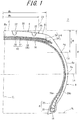
- FIG. 1 illustrates a pneumatic tire 2.
- the up-down direction represents the radial direction of the tire 2
- the right-left direction represents the axial direction of the tire 2
- the direction perpendicular to the surface of the sheet represents the circumferential direction of the tire 2.
- An alternate long and short dash line CL in FIG. 1 represents the equator plane of the tire 2.
- the tire 2 has a shape which is symmetric about the equator plane except for a tread pattern.
- An alternate long and two short dashes line BL represents the bead base line of the tire 2.
- the tire 2 includes a tread 4, sidewalls 6, beads 8, a carcass 10, a belt 12, a band 14, an inner liner 16, and chafers 18.
- the tire 2 is of a tubeless type.
- the tire 2 is mounted to passenger cars.
- the tread 4 has a shape that projects outward in the radial direction.
- the tread 4 has a center region C and shoulder regions S.
- the center region C is disposed at the center, in the axial direction, of the tire 2.
- the paired shoulder regions S are disposed outward of the center region C in the axial direction.
- the tread 4 forms a tread surface 20 that can contact with a road surface.
- the tread surface 20 has grooves 22 formed therein. A tread pattern is formed by the grooves 22.
- the tread 4 includes a base layer and a cap layer, which are not shown.
- the cap layer is disposed outward of the base layer in the radial direction.
- the cap layer is layered over the base layer.
- the base layer is formed of a crosslinked rubber excellent in adhesiveness.
- a typical base rubber of the base layer is a natural rubber.
- the cap layer is formed of a crosslinked rubber excellent in wear resistance, heat resistance, and grip performance.
- Each sidewall 6 extends from the edge of the tread 4 in almost radially inward direction.
- the outer ends, in the radial direction, of the sidewalls 6 are joined to the tread 4.
- the sidewalls 6 are formed of a crosslinked rubber excellent in cut resistance and weather resistance. The sidewalls 6 prevent the carcass 10 from being damaged.
- Each bead 8 includes a core 24 and an apex 26 that extends outward of the core 24 in the radial direction.
- the core 24 is ring-shaped, and includes a non-stretchable wound wire.
- a typical material of the wire is a steel.
- the apex 26 is tapered outward in the radial direction.
- the apex 26 is formed of a highly hard crosslinked rubber.
- the carcass 10 includes a carcass ply 28.
- the carcass ply 28 is extended along the tread 4 and the sidewalls 6 on and between the beads 8 on both sides.
- the carcass ply 28 is turned up around each core 24 from the inner side toward the outer side in the axial direction.
- the carcass ply 28 By the carcass ply 28 being turned up, the carcass ply 28 includes a main body portion 28a and turned-up portions 28b.
- the carcass ply 28 is formed of multiple cords aligned with each other, and a topping rubber.
- An absolute value of an angle of each cord relative to the equator plane ranges from 75° to 90°.
- the carcass 10 forms a radial structure.
- the cords are formed of an organic fiber.
- Preferable examples of the organic fiber include polyester fibers, nylon fibers, rayon fibers, polyethylene naphthalate fibers, and aramid fibers.
- the carcass 10 may be formed of two or more plies.
- the belt 12 is disposed inward of the tread 4 in the radial direction.
- the belt 12 is layered over the carcass 10.
- the belt 12 reinforces the carcass 10.
- the belt 12 includes an inner layer 30, and an outer layer 32 disposed outward of the inner layer 30 in the radial direction so as to be layered over the inner layer 30.
- the width of the inner layer 30 is slightly greater than the width of the outer layer 32 in the axial direction.
- Each of the inner layer 30 and the outer layer 32 is formed of multiple cords aligned with each other, and a topping rubber, which are not shown. Each cord is inclined relative to the equator plane.
- the absolute value of the inclination angle is typically greater than or equal to 10°, and not greater than 35°.
- a direction in which the cords of the inner layer 30 are inclined relative to the equator plane and a direction in which the cords of the outer layer 32 are inclined relative to the equator plane are opposite to each other.
- a material of each cord is preferably a steel.
- an organic fiber may be used for each cord.
- a double-headed arrow Wb in FIG. 1 represents a width of the belt 12.
- the width Wb of belt 12 is measured as a distance in a straight line in the axial direction of the tire 2.
- the width Wb is measured as a width of a range in which the inner layer 30 and the outer layer 32 are layered over each other.
- the width Wb is measured as a width of the outer layer 32.
- the width Wb is preferably greater than or equal to 0.58 times the maximum width of the tire 2, and preferably not greater than 0.85 times the maximum width of the tire 2.
- the band 14 is disposed outward of the belt 12 in the radial direction.
- the band 14 includes a full band 34 and a pair of edge bands 36.
- the width of the full band 34 is greater than the width of the belt 12 in the axial direction.
- the full band 34 covers the belt 12.
- the full band 34 is formed of a cord and a topping rubber, which are not shown.
- the cord of the full band 34 is helically wound.
- the full band 34 has a so-called jointless structure.
- the cord of the full band 34 extends substantially in the circumferential direction. An angle of the cord relative to the circumferential direction is less than or equal to 5°, and more preferably less than or equal to 2°.
- the pair of edge bands 36 cover end portions, in the axial direction, of the belt 12.
- the edge bands 36 are disposed outward of the full band 34 in the radial direction, and layered over end portions, in the axial direction, of the full band 34.
- Each edge band 36 is formed of a cord and a topping rubber.
- the cord of each edge band 36 is helically wound.
- the edge bands 36 has a so-called jointless structure.
- the cord of the edge bands 36 extends substantially in the circumferential direction.
- An angle of the cord relative to the circumferential direction is less than or equal to 5°, and more preferably less than or equal to 2°.
- the edge bands 36 may be disposed inward of the full band 34 in the radial direction and layered.
- the cord of each edge band 36 may extend substantially in the axial direction.
- the belt 12 is held by the band 14, thereby reducing lifting of the belt 12.
- the cords of the band are formed of an organic fiber.
- the organic fiber include nylon fibers, polyester fibers, rayon fibers, polyethylene naphthalate fibers, and aramid fibers.
- the belt 12 and the band 14 form a reinforcing layer.
- the reinforcing layer may be formed merely by the belt 12.
- the inner liner 16 is disposed inward of the carcass 10.
- the inner liner 16 is formed of a crosslinked rubber.
- a rubber excellent in airtightness is used.
- a typical base rubber of the inner liner 16 is an isobutylene-isoprene-rubber or halogenated isobutylene-isoprene-rubber.
- the inner liner 16 maintains internal pressure of the tire.
- the chafers 18 are disposed near the beads 8. When the tire 2 is mounted to a rim, the chafers 18 contact with the rim. Regions near the beads 8 are protected due to the contact.
- the chafers 18 are formed of a fabric and a rubber impregnated into the fabric.
- a point Pa represents a point of intersection between the equator plane and the tread surface 20.
- An alternate long and two short dashes line Lh represents a straight line that extends in the radial direction.
- a double-headed arrow Wh represents a width between one straight line Lh on one side in the axial direction and the other straight line Lh, on the other side in the axial direction, which is not shown.
- the width Wh is 0.8 times the width Wb of the belt 12, that is, 0.8 ⁇ Wb.
- a point Ph represents a point of intersection between the straight line Lh and the tread surface 20.
- An alternate long and two short dashes line Le represents a straight line that extends in the axial direction with the maximum width of the tire 2.
- the maximum width represents a width, in the axial direction, of the tire between axially outermost positions of the main body portion 28a of the carcass 10 which is extended.
- a point Pe represents a point of intersection between the straight line Le and an axially outer side surface 6a of each sidewall 6.
- the maximum width of the tire 2 is measured as a distance from the point Pe to the point Pe on the other side, which is not shown.
- a double-headed arrow D represents a distance, in the radial direction, from the point Pa to the point Pe.
- An alternate long and two short dashes line Ld represents a straight line that extends in the axial direction through the midpoint of the distance D.
- a point Pd represents a point of intersection between the straight line Ld and the axially outer side surface 6a of each sidewall 6.
- the point Pd represents the midpoint, in the radial direction, between the point Pa and the point Pe.
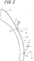
- FIG. 2 is an enlarged view of a portion of the tire 2.
- the axially outer side surface 6a of the tire 2 represents a state where the tire 2 is mounted to a normal rim, and is inflated with air to a normal internal pressure P.
- An alternate long and two short dashes line 6a' also represents the axially outer side surface of the tire 2.
- the outer side surface 6a' represents a state where the tire 2 is mounted to a normal rim, and is inflated with air to an air pressure of 0.05 ⁇ P which is 0.05 times the normal internal pressure P.
- a point Pd' represents a point of intersection between the outer side surface 6a' and a normal line to the axially outer side surface 6a at the point Pd.
- a double-headed arrow Dd represents a distance from the point Pd' to the point Pd.
- the distance Dd represents an amount of protrusion of the tire 2 at the point Pd.
- the amount of protrusion Dd represents a distance from the point Pd' to the point Pd in a state where the tire is pressurized to shift from the air pressure of 0.05 ⁇ P to the air pressure P.
- the amount of protrusion Dd is represented so as to indicate a plus value in the case of shift in the axially outward direction and indicate a minus value in the case of shift in the axially inward direction.
- a point Pe' represents a point of intersection between the straight line Le and the outer side surface 6a'.
- a double-headed arrow De represents a distance from the point Pe' to the point Pe.
- the distance De represents an amount of protrusion of the tire 2 at the point Pe.
- the amount of protrusion De represents a distance from the point Pe' to the point Pe in a state where the tire is pressurized to shift from the air pressure of 0.05 ⁇ P to the air pressure P.
- the amount of protrusion De is represented so as to indicate a plus value in the case of shift in the axially outward direction, and indicate a minus value in the case of shift in the axially inward direction.
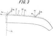
- FIG. 3 is an enlarged view of another portion of the tire 2.
- the tread surface 20 of the tire 2 represents a state where the tire 2 is mounted to a normal rim, and is inflated with air to a normal internal pressure P.
- An alternate long and two short dashes line 20' also represents the tread surface of the tire 2.
- the tread surface 20' represents a state where the tire 2 is mounted to a normal rim, and is inflated with air to an air pressure of 0.05 ⁇ P which is 0.05 times the normal internal pressure P.
- a point Pa' represents a point of intersection between the equator plane and the tread surface 20'.
- a double-headed arrow Da represents a distance from the point Pa' to the point Pa.
- the distance Da represents an amount of protrusion of the tire 2 at the point Pa.
- the amount of protrusion Da represents a distance from the point Pa' to the point Pa in a state where the tire is pressurized to shift from the air pressure of 0.05 ⁇ P to the air pressure P.
- the amount of protrusion Da is represented so as to indicate a plus value in the case of shift in the radially outward direction, and indicate a minus value in the case of shift in the radially inward direction.
- a point Ph' represents a point of intersection between the tread surface 20' and a normal line to the tread surface 20 at the point Ph.
- a double-headed arrow Dh represents a distance from the point Ph' to the point Ph.
- the distance Dh represents an amount of protrusion of the tire 2 at the point Ph.
- the amount of protrusion Dh represents a distance from the point Ph' to the point Ph in a state where the tire is pressurized to shift from the air pressure of 0.05 ⁇ P to the air pressure P.
- the amount of protrusion Dh is represented so as to indicate a plus value in the case of shift in the radially outward direction and indicate a minus value in the case of shift in the radially inward direction.
- the tire 2 is mounted to a normal rim and is inflated with air to the air pressure of 0.05 ⁇ P.
- a profile of the tire 2 under the air pressure of 0.05 ⁇ P is measured by a profile measurement machine. Further, the tire is inflated with air to the air pressure P.
- a profile of the tire 2 under the air pressure P is measured by the profile measurement machine.
- the point Pa, the point Ph, the point Pe, and the point Pd are obtained based on the profile of the tire 2 under the air pressure P.
- the profile of the tire 2 under the air pressure P and the profile of the tire 2 under the air pressure of 0.05 ⁇ P are overlaid on each other such that bead positions (rim flange positions) of the profiles are aligned with each other.
- the point Pa', the point Ph', the point Pe', and the point Pd' are obtained based on the profile of the tire 2 under the air pressure of 0.05 ⁇ P.
- the amount of protrusion Da and the amount of protrusion Dh for the tread 4, and the amount of protrusion Dd and the amount of protrusion De for each sidewall 6 are obtained.
- the aspect ratio is 70%.
- the sum Fa of the amounts of protrusions satisfies the following relational expression. ⁇ 0.02 ⁇ Fa ⁇ 1.18
- the shoulder region S of the tread 4 is likely to protrude in the radially outward direction.
- the protruding of the shoulder region S expansion of the openings of the grooves 22 is reduced.
- the sum Fa of the amounts of protrusions is greater than -0.02. Therefore, expansion of the openings of the grooves 22 is reduced.
- generation of cracks in the groove bottoms is reduced.
- the high aspect ratio represents an aspect ratio that is higher than or equal to 65%.
- a difference Gs in the amount of protrusion for the tread 4 is calculated based on a difference between the amount of protrusion Da and the amount of protrusion Dh, and the nominal width W of the tire 2, according to following expression.
- Gs Da ⁇ Dh / W ⁇ 100
- openings of the grooves 22 are likely to be expanded. Openings of the grooves 22 that extend in the circumferential direction are likely to be expanded. In particular, openings of the grooves 22 disposed in the shoulder region S are likely to be expanded.
- tensile stress is applied, in the groove width direction, to the bottom portions of the grooves 22 that extend in the circumferential direction. Due to the tensile stress, cracks are likely to be generated in the bottom portions of the grooves 22. Further, contact pressure of the tread surface 20 in the shoulder region S is enhanced. Uneven wear of the tread surface 20 in the shoulder region S is increased.
- the difference Gs in the amount of protrusion is greater than -0.84.
- the amount of protrusion Dh is less likely to be excessively increased with respect to the amount of protrusion Da.
- generation of cracks in the bottom portions of the grooves 22 is reduced. Uneven wear of the tread surface 20 in the shoulder region S is reduced.
- the center region C of the tread 4 protrudes in the radially outward direction. In the center region C, contact pressure at the tread 4 is enhanced.
- wear is likely to increase at the tread surface 20 in the center region C in which contact pressure is high.
- the tread surface 20 in the shoulder region S in which contact pressure is low is likely to slide. Thus, wear of the tread surface 20 in the shoulder region S is likely to increase.
- the difference Gs in the amount of protrusion is less than -0.09 (-0.086).
- the amount of protrusion Da is less likely to be excessively increased with respect to the amount of protrusion Dh.
- the center region C is less likely to protrude.
- uneven wear of the tread surface 20 is reduced.
- the sum Fa of the amounts of protrusions and the difference Gs in the amount of protrusion are each represented as a ratio with respect to the nominal width W of the tire 2.
- the sum Fa in the amount of protrusion and the difference Gs in the amount of protrusion are applicable to tires having different nominal widths W.
- protrusion of the shoulder regions S of the tread surface 20 is reduced.
- protrusion of the shoulder region S is small.
- the shoulder region S is likely to be protruded.
- an effect of reducing protrusion by the edge bands 36 is great.
- the dimensions and angles of the components of the tire 2 are measured in a state where the tire 2 is mounted to a normal rim, and inflated with air to a normal internal pressure, unless otherwise specified. During the measurement, no load is applied to the tire 2.
- the normal rim represents a rim that is specified according to the standard with which the tire 2 complies.
- the "standard rim” in the JATMA standard, the "Design Rim” in the TRA standard, and the “Measuring Rim” in the ETRTO standard are included in the normal rim.
- the normal internal pressure represents an internal pressure that is specified according to the standard with which the tire complies.
- FIG. 4 illustrates another pneumatic tire 42 according to the present invention.
- the tire 42 includes a tread 44, sidewalls 46, beads 48, a carcass 50, a belt 52, a band 54, an inner liner 56, and chafers 58.
- the tread 44 forms a tread surface 60 that can contact with a road surface.
- the tread surface 60 has grooves 62 formed therein.
- Each bead 48 includes a core 64 and an apex 66 that extends outward of the core 64 in the radial direction.
- the carcass 50 includes a first ply 68 and a second ply 70.
- the first ply 68 and the second ply 70 are extended along the tread 44 and the sidewalls 46 on and between the beads on both sides.
- the first ply 68 is turned up around each core 64 from the inner side toward the outer side in the axial direction.
- the first ply 68 includes a main body portion 68a and turned-up portions 68b.
- the second ply 70 is turned up around each core 64 from the inner side toward the outer side in the axial direction.
- the second ply 70 By the second ply 70 being turned up, the second ply 70 includes a main body portion 70a and turned-up portions 70b.
- the ends of the turned-up portions 68b of the first ply 68 are disposed radially outward of the ends of the turned-up portions 70b of the second ply 70.
- Each of the first ply 68 and the second ply 70 is formed of multiple cords aligned with each other, and a topping rubber.
- An absolute value of an angle of each cord relative to the equator plane ranges from 75° to 90°.
- the carcass forms a radial structure.
- the cords are formed of an organic fiber.
- Preferable examples of the organic fiber include polyester fibers, nylon fibers, rayon fibers, polyethylene naphthalate fibers, and aramid fibers.
- the carcass 50 may be formed of one ply.
- the belt 52 is disposed inward of the tread 44 in the radial direction.
- the belt 52 is layered over the carcass 50.
- the belt 52 includes an inner layer 72 and an outer layer 74.
- Each of the inner layer 72 and the outer layer 74 is formed of multiple cords aligned with each other, and a topping rubber, which are not shown.
- Each cord is inclined relative to the equator plane.
- the absolute value of the inclination angle is typically greater than or equal to 10° and not greater than 35°.
- a direction in which the cords of the inner layer 72 are inclined relative to the equator plane is opposite to a direction in which the cords of the outer layer 74 are inclined relative to the equator plane.
- the band 54 is disposed outward of the belt 52 in the radial direction.
- the band 54 includes a full band 76 and a pair of edge bands 78.
- the width of the full band 76 is greater than the width of the belt 52 in the axial direction.
- the full band 76 and the edge bands 78 are each formed of a cord and a topping rubber, which are not shown.
- the cords are helically wound.
- the full band 76 and the edge bands 78 each have a so-called jointless structure.
- the cords of the full band 76 and the edge bands 78 extend substantially in the circumferential direction.
- the cords of the edge bands 78 may extend substantially in the axial direction.
- the edge bands 78 may be disposed inward of the full band 76 in the radial direction and layered.
- the belt 52 and the band 54 form a reinforcing layer.
- an aspect ratio is 40%.
- a sum Fa of amounts of protrusions satisfies the following relational expression. ⁇ 0.81 ⁇ Fa ⁇ 0.39
- the low aspect ratio represents an aspect ratio that is less than or equal to 50%.
- the sum Fa of the amounts of protrusions is less than 0.39. Therefore, expansion of the openings of the grooves 62 that extend in the circumferential direction is reduced. In the tire 42, generation of cracks in the groove bottoms is reduced.
- the span of each sidewall 46 in the radial direction is short. Since the span in the radial direction is short, when both the amount of protrusion Dd and the amount of protrusion De are reduced, the shoulder region S of the tread 44 is likely to protrude in the radially outward direction. In the shoulder region S, contact pressure at the tread 44 is enhanced. In the shoulder region S, the tread surface 60 is likely to be worn.
- the sum Fa of the amounts of protrusions is greater than -0.81. Therefore, the shoulder region S is less likely to be greatly protruded. In the tire 42, uneven wear of the shoulder region S is reduced.
- the difference Gs in the amount of protrusion satisfies the following relational expression. ⁇ 0.52 ⁇ Gs ⁇ 0.24
- the difference Gs in the amount of protrusion is greater than -0.52.
- the amount of protrusion Dh is less likely to be excessively increased with respect to the amount of protrusion Da.
- generation of cracks in the bottom portions of the grooves 62 is reduced. Further, uneven wear of the tread surface 60 in the shoulder region S is reduced.
- the difference Gs in the amount of protrusion is less than 0.24. Therefore, the amount of protrusion Da is less likely to be excessively increased with respect to the amount of protrusion Dh. In the tire 42, the center region C is less likely to protrude. In the tire 42, uneven wear of the tread surface 60 is reduced.
- Preferable ranges for the sum Fa of the amounts of protrusions and the difference Gs in the amount of protrusion are each different according to the aspect ratio A as described for the tire 2 and the tire 42 as examples.
- FIG. 5 shows a graph representing a distribution, of sample tires, based on the aspect ratio A and the sum Fa of the amounts of protrusions.
- circle marks represent a distribution of the sample tires in which generation of cracks and generation of uneven wear of the shoulder region S were favorably reduced.
- X marks represent a distribution of the sample tires in which at least one of cracks and uneven wear of the shoulder region S was unfavorably generated. According to the graph, it has been confirmed that, in the sample tires in which the value Fa is less than values on a straight line Lv and greater than values on a straight line Lw, generation of cracks in the groove bottoms and generation of uneven wear are particularly favorably reduced.
- FIG. 6 shows a graph representing a distribution, of sample tires, based on the aspect ratio A and the difference Gs in the amount of protrusion.
- circle marks represent a distribution of the sample tires in which generation of cracks and generation of uneven wear of the shoulder region S were favorably reduced.
- X marks represent a distribution of the sample tires in which at least one of cracks and uneven wear of the shoulder region S was unfavorably generated.
- the straight line Lu may be represented by the following expression.
- Gs ⁇ 0.010819 ⁇ A ⁇ 0.084658
- the manufacturing method includes a determination step of evaluating durability of a sample tire.
- a sample tire for obtaining the tire 2 is prepared. Whether or not the sample tire is good is determined based on the sum Fa of the amounts of protrusions and the difference Gs in the amount of protrusion. Based on evaluation results in the determination step, the tire 2 is designed. For example, when the sample tire is determined as being not good, a carcass line is adjusted such that each of the sum Fa of the amounts of protrusions and the difference Gs in the amount of protrusion is within a predetermined range.
- the carcass line is adjusted by adjusting, for example, a shape of a mold for vulcanization and molding.
- a radius of curvature of the carcass line near the point Pd and a radius of curvature of the carcass line near the point Pe are adjusted by the shape of the mold.
- the tire 2 is manufactured according to the mold for forming the sample tire. In this manner, the tire 2 is designed and manufactured according to the sample tire, thereby facilitating manufacturing of the tire 2 excellent in durability.
- a method for adjusting the carcass line is described as an exemplary method.
- the adjustment method is not limited to the above-described exemplary method.
- the adjustment can be made by adjusting a thickness of rubber of the sidewall 6 near the point Pd and a thickness of rubber of the sidewall 6 near the point Pe.
- the structure of the band 14 of the tire 2 may be changed.
- the evaluation method includes a step of obtaining a tire assembly, a low internal pressure step, a normal internal pressure step, and a determination step.
- the tire 2 is mounted to a normal rim, to obtain a tire assembly.
- the tire assembly is inflated with air to an air pressure of 0.05 ⁇ P, as an internal pressure, which is 0.05 times the normal internal pressure P.
- an air pressure of 0.05 ⁇ P as an internal pressure, which is 0.05 times the normal internal pressure P.
- the tire assembly is inflated with air to the normal internal pressure.
- a profile of the tire 2 is obtained.
- positions of the point Pa, the point Ph, the point Pd, and the point Pe are obtained based on the profile obtained in the normal internal pressure step. Further, positions of the point Pa', the point Ph', the point Pd', and the point Pe' are obtained based on the profile obtained in the low internal pressure step.
- the amounts of protrusions Da and Dh for the tread 4 and the amounts of protrusions De and Dd for each sidewall 6 are calculated.
- the difference Gs in the amount of protrusion for the tread 4 and the sum Fa of the amounts of protrusions for each sidewall 6 are calculated. Whether or not each of the sum Fa of the amounts of protrusions and the difference Gs in the amount of protrusion is within a predetermined range is determined for evaluation. When the sum Fa and the difference Gs are each within the predetermined range, the evaluation result is determined as being good. When each of the sum Fa and the difference Gs is not within the predetermined range, the evaluation result is determined as being not good.
- durability of the tire 2 can be efficiently determined in terms of generation of cracks in the bottom portions of the grooves 22, and generation of uneven wear of the tread 4.
- a tire having the fundamental structure shown in FIG. 1 was produced as a sample of a tire.
- the size of the tire was "185/70R14". That is, the nominal width W of the tire was 185 (mm), and the aspect ratio A thereof was 70%.
- the tire was mounted to a normal rim of 14 ⁇ 5.5J.
- the tire was inflated with air to an internal pressure of 12 kPa. Thereafter, the tire was inflated with air to the normal internal pressure of 240 kPa.
- the amount of protrusion Da (mm), the amount of protrusion Dh (mm), the amount of protrusion Dd (mm), the amount of protrusion De (mm), the difference Gs in the amount of protrusion, and the sum Fa of the amounts of protrusions, were obtained. The results are indicated in Table 1.
- Tires were produced as samples of tires in the same manner as for example 1 except that the carcass lines were adjusted.
- the amounts of protrusions Da (mm), Dh (mm), Dd (mm), and De (mm)
- the difference Gs in the amount of protrusion were obtained.
- the results are indicated in Table 1.
- Tires were produced as samples of tires in the same manner as for example 1 except that the band structures were different and the carcass lines were adjusted.
- the amounts of protrusions Da (mm), Dh (mm), Dd (mm), and De (mm)
- the difference Gs in the amount of protrusion were obtained.
- the results are indicated in Table 2.
- a tire having the fundamental structure shown in FIG. 4 was produced as a sample of a tire.
- the size of the tire was "225/40R18". That is, the nominal width W of the tire was 225 (mm), and the aspect ratio A thereof was 40%.
- the tire was mounted to a normal rim of 18 ⁇ 8J.
- the tire was inflated with air to an internal pressure of 12 kPa. Thereafter, the tire was inflated with air to the normal internal pressure of 240 kPa.
- the amount of protrusion Da (mm) and the amount of protrusion Dh (mm) for a tread, and the amount of protrusion Dd (mm) and the amount of protrusion De (mm) for a sidewall, were obtained.
- the difference Gs in the amount of protrusion and the sum Fa of the amounts of protrusions, were obtained. The results are indicated in Table 3.
- Tires were produced as samples of tires in the same manner as for example 8 except that the carcass lines were adjusted.
- the amounts of protrusions Da (mm), Dh (mm), Dd (mm), and De (mm)
- the difference Gs in the amount of protrusion were obtained.
- the results are indicated in Table 3.
- Tires were produced as samples of tires in the same manner as for example 8 except that the band structures were different and the carcass lines were adjusted.
- the amounts of protrusions Da (mm), Dh (mm), Dd (mm), and De (mm)
- the difference Gs in the amount of protrusion were obtained.
- the results are indicated in Table 4.
- the tires produced as the samples of tires were mounted to the normal rims, to obtain tire assemblies.
- Each tire assembly was inflated with air to the normal internal pressure.
- Bottoms of the main grooves formed in the shoulder region in the circumferential direction in each tire were cut in the circumferential direction.
- a razor blade having a thickness of 0.25 mm was used to cut the bottoms of the main grooves by a depth of 2 mm and a length of 8 mm.
- Shapes of the cut openings were taken and an amount of expansion of the cut opening was measured. The measurement results are indicated as indexes in Tables 1 to 4. The less the amount of expansion of the cut opening is, the greater the index is. The greater the index is, the less generation of cracks is.
- the tires produced as the samples of tires were mounted to the normal rims, to obtain tire assemblies.
- Each tire assembly was inflated with air to the normal internal pressure.
- Each tire assembly was mounted to a bench measurement device for measuring wear energy.
- the tire assembly was set so as to be rotatable.
- a slip angle was set as 1°.
- the tire was under a load that was 80% of the maximum load in the load index standard.
- the tire was settled on a setting table of the bench measurement device for measuring wear energy. Thus, wear energy of each tire in a turning state was measured.
- a wear energy Es in the shoulder region on the outer side in the turning radius direction and a wear energy Ec at the center region were measured.
- a wear energy ratio (Es/Ec) of the wear energy Es to the wear energy Ec was obtained.
- the wear energy ratio (Es/Ec) is indicated as an index and the results are indicated in Tables 1 to 6. The less the wear energy ratio (Es/Ec) is, the greater the index is. The greater the index is, the less generation of uneven wear of the shoulder region is.
- Example 10 Comparative example 6 Da (mm) 0.62 0.74 1.04 1.16 1.28 Dh (mm) 1.88 1.65 1.87 0.86 0.63 Dd (mm) -1.81 -0.81 -0.56 0.46 0.46 De (mm) 0.17 0.17 -0.37 -0.68 -0.68 Gs -0.56 -0.41 -0.37 0.13 0.29 Fa -0.29 -0.29 -0.41 -0.10 -0.10 Band structure 1E+1F 1E+1F 1E+1F 1E+1F 1E+1F 1E+1F Expansion of cut in groove 6.6 7.3 7.5 8.1 8.8 Wear at shoulder region 7.6 8.1 9.2 7.4 6.8
- the pneumatic tire can be excellent in resistance to uneven wear and crack resistance in grooves (see examples 1 to 14) .
- the tire and the method for testing durability of the tire as described above are also applicable to various pneumatic tires for use in passenger cars, lightweight trucks, small trucks, trucks, buses, two-wheeled automotive vehicles, and to durability tests for the pneumatic tires.
Landscapes
- Engineering & Computer Science (AREA)
- Mechanical Engineering (AREA)
- Physics & Mathematics (AREA)
- General Physics & Mathematics (AREA)
- Tires In General (AREA)
Claims (6)
- Luftreifen (2, 42), mit:einem Profil (4, 44), das eine äußere Fläche hat, die eine Profilfläche (20, 60) ausbildet;einem Paar Seitenwände (6, 46), die sich nahezu einwärts von jeweiligen Enden des Profils (4, 44) in einer Radialrichtung erstrecken;einem Paar Wülste (8, 48) die einwärts der Seitenwände (6, 46) in der Radialrichtung angeordnet sind;einer Karkasse (10, 50) die sich entlang von Innenseiten des Profils (4, 44) und der Seitenwände (6, 46) erstreckt; undeinem Gürtel (12, 52) der außerhalb der Karkasse (10, 50) in der Radialrichtung angeordnet ist und über der Karkasse (10, 50) geschichtet ist, wobeider Gürtel (12, 52) eine Innenschicht (30, 72) und eine Außenschicht (32, 74) hat, die außerhalb der Innenschicht (30, 72) in der Radialrichtung angeordnet ist und über der Innenschicht (30, 72) geschichtet ist,die Profilfläche (20, 60) Nuten (22, 62) hat, die ausgebildet sind, um sich in einer Umfangsrichtung zu erstrecken,die Karkasse (10, 50) eine Karkassenlage (28) hat, und die Karkassenlage (28) einen Hauptkörperabschnitt (28a) ausbildet, der sich auf und zwischen einer der Wülste (8, 48) und der anderen der Wülste (8, 48) erstreckt,ein normaler Innendruck durch P angegeben ist,ein Zustand, in dem der Reifen (2, 42) mit einer Luft bis zu einem Luftdruck von 0,05 mal dem normalen Innendruck P aufgepumpt ist, ein Niederdruckzustand ist,ein Zustand, in dem der Reifen (2, 42) mit einer Luft bis zu dem normalen Innendruck P aufgepumpt ist, ein normaler Druckzustand ist,eine Position auf einer Äquatorebene der Profilfläche (20, 20', 60) als ein Punkt Pa in dem normalen Druckzustand und als ein Punkt Pa' in den Niederdruckzustand angegeben ist,Positionen auf der Profilfläche (20, 60) in dem normalen Druckzustand, die voneinander um 0,8 mal einer Breite Wb in einer Axialrichtung eines Bereichs entfernt sind, in dem die Innenschicht (30, 72) und die Außenschicht (32, 74) des Gürtels (12, 52) übereinander geschichtet sind, jeweils als ein Punkt Ph in dem normalen Druckzustand angegeben sind,Positionen auf der Profilfläche (20') in dem Niederdruckzustand, bei einem Schnittpunkt zwischen der Profilfläche (20') in dem Niederdruckzustand und einer normalen Linie zu der Profilfläche (20) an dem Punkt Ph, jeweils als ein Punkt Ph' angegeben sind,Positionen auf axial äußeren Seitenflächen (6a, 6a') der Seitenwände (6, 46), die voneinander mit einer maximalen Breite entfernt sind, jeweils als ein Punkt Pe in dem normalen Druckzustand und als ein Punkt Pe' in dem Niederdruckzustand angegeben sind,Positionen auf den axial äußeren Seitenflächen (6a) der Seitenwände (6, 46) in dem normalen Druckzustand, von denen jede ein Mittelpunkt zwischen dem Punkt Pa und dem Punkt Pe in der Radialrichtung ist, jeweils als ein Punkt Pd angegeben sind,Positionen auf dem auf den axial äußeren Seitenflächen (6a') der Seitenwände (6, 46) in dem Niederdruckzustand an einem Schnittpunkt zwischen der äußeren Seitenfläche (6a') in dem Niederdruckzustand und einer normalen Linie zu der axial äußeren Seitenfläche (6a) an dem Punkt Pd jeweils als ein Punkt Pd' angegeben sind,eine Nennbreite des Reifens als W (mm) angegeben ist,die maximale Breite eine Breite in der Axialrichtung zwischen radialen Positionen ist, bei denen der Hauptkörperabschnitt (28a) der Karkassenlage (28) an axial äußersten Positionen ist,ein Abstand von dem Punkt Pa' zu dem Punkt Pa als ein Vorsprungsumfang Da (mm) angegeben ist, ein Abstand von dem Punkt Ph' zu dem Punkt Ph als ein Vorsprungsumfang Dh (mm) angegeben ist, ein Abstand von den Punkt Pd' zu dem Punkt Pd als ein Vorsprungsumfang Dd (mm) angegeben ist, und ein Abstand von dem Punkt Pe' zu dem Punkt Pe als ein Vorsprungsumfang De (mm) angegeben ist,wenn eine Summe Fa der Vorsprungsumfänge für jede Seitenwand gemäß einem mathematischen Ausdruck (1) erlangt wird, die Summe Fa der Vorsprungsumfänge mathematische Ausdrücke (2) und (3) erfüllt, bei denen ein Querschnittsverhältnis A verwendet wird, undwenn eine Differenz Gs bei dem Vorsprungsumfang des Profils (4, 44) gemäß einem mathematischen Ausdruck (4) erlangt wird, die Differenz Gs bei dem Vorsprungsumfang mathematische Ausdrücke (5) und (6) erfüllt, wobei die mathematischen Ausdrücke (1) bis (6) Folgende sind:


- Reifen (2, 42) nach Anspruch 1, miteinem Band (14, 54) das außerhalb des Gürtels (12, 52) in der Radialrichtung angeordnet ist und über dem Gürtel (12, 52) geschichtet ist, wobeidas Band (14, 54) ein Vollband (34, 76) und ein paar Randbänder (36, 78) umfasst, die über Endabschnitten in der Axialrichtung des Vollbands (34, 76) geschichtet sind,dass Vollband (34, 76) einen Cord und ein Belaggummi umfasst, und wobei sich der Cord im Wesentlichen in der Umfangsrichtung erstreckt, undjedes Randband (36, 78) einen Cord und einen Belaggummi umfasst, und wobei sich der Cord im Wesentlichen in der Umfangsrichtung oder der Axialrichtung erstreckt.
- Reifen (2, 42) nach Anspruch 1 oder 2, wobeidas Querschnittsverhältnis A 70% ist,die Summe Fa der Vorsprungsumfänge größer als -0,02 und geringer als 1,18 ist, unddie Differenz Gs bei dem Vorsprungsumfang größer als -0,84 und geringer als -0,09 ist.
- Reifen (2, 42) nach Anspruch 1 oder 2, wobeidas Querschnittsverhältnis A 40% ist,die Summe Fa der Vorsprungsumfänge größer als -0,81 und geringer als 0,39 ist, unddie Differenz Gs bei dem Vorsprungsumfang größer als -0,52 und geringer als 0,24 ist.
- Lebensdauerbewertungsverfahren für einen Reifen (2, 42) der Folgendes aufweist: ein Profil (4, 44), das eine äußere Fläche hat, die eine Profilfläche (20, 60) ausbildet; ein paar Seitenwände (6, 46), die sich nahezu einwärts von jeweiligen Enden des Profils (4, 44) in einer Radialrichtung erstrecken; ein paar Wülste (8, 48), die einwärts der Seitenwände (6, 46) in der Axialrichtung angeordnet sind; eine Karkasse (10, 50), die sich entlang von Innenseiten des Profils (4, 44) und der Seitenwände (6, 46) erstreckt; und einen Gürtel (12, 52), der außerhalb der Karkasse (10, 50) in der Radialrichtung angeordnet ist und über der Karkasse (10, 50) geschichtet ist, und bei dem: der Gürtel (12, 52) eine Innenschicht (30, 72) und eine Außenschicht (32, 74) hat, die außerhalb der Innenschicht (30, 72) in der Radialrichtung angeordnet ist und über der Innenschicht (30, 72) geschichtet ist; die Profilfläche (20, 60) Nuten (22, 62) hat, die ausgebildet sind, um sich in einer Umfangsrichtung zu erstrecken; die Karkasse (10, 50) eine Karkassenlage (28) hat; und die Karkassenlage (28) einen Hauptkörperabschnitt (28a) ausbildet, der sich auf und zwischen einer der Wülste (8, 48) und der anderen der Wülste (8, 48) erstreckt, wobeiein normaler Innendruck mit P angegeben wird,ein Zustand, in dem der Reifen (2, 42) mit einer Luft bis zu einem Luftdruck von 0,05 mal dem normalen Innendruck P aufgepumpt ist, ein Niederdruckzustand ist,ein Zustand, in dem der Reifen (2, 42) mit einer Luft bis zu dem normalen Innendruck P aufgepumpt ist, ein normaler Druckzustand ist,eine Position auf einer Äquatorebene der Profilfläche (20, 20', 60) als ein Punkt Pa in dem normalen Druckzustand und als ein Punkt Pa' in dem Niederdruckzustand angegeben wird,Positionen auf der Profilfläche (20, 60) in dem normalen Druckzustand, die voneinander um 0,8 mal eine Breite Wb in einer Axialrichtung eines Bereichs entfernt sind, in dem die Innenschicht (30, 72) und die Außenschicht (32, 74) des Gürtels (12, 52) übereinander geschichtet sind, jeweils als ein Punkt Ph in dem normalen Druckzustand angegeben werden,Positionen auf der Profilfläche (20') in dem Niederdruckzustand bei einem Schnittpunkt zwischen der Profilfläche (20') in dem Niederdruckzustand und einer normalen Linie zu der Profilfläche (20) an dem Punkt Ph jeweils als ein Punkt Ph' angegeben werden,Positionen auf axial äußeren Seitenflächen (6a, 6a') der Seitenwände (6, 46), die voneinander mit einer maximalen Breite entfernt sind, jeweils als ein Punkt Pe in den normalen Druckzustand und als ein Punkt Pe' in dem Niederdruckzustand angegeben werden,Positionen auf den axial äußeren Seitenflächen (6a) der Seitenwände (6, 46) in dem normalen Druckzustand, von denen jede ein Mittelpunkt wischen dem Punkt Pa und dem Punkt Pe in der Radialrichtung ist, jeweils als ein Punkt Pd angegeben werden,Positionen auf den axial äußeren Seitenflächen (6a') der Seitenwände (6, 46) in dem Niederdruckzustand bei einem Schnittpunkt zwischen der äußeren Seitenfläche (6a') in dem Niederdruckzustand und einer normalen Linie zu der axial äußeren Seitenfläche (6a) an dem Punkt Pd jeweils als ein Punkt Pd' angegeben werden,eine Nennbreite des Reifens als W (mm) angegeben wird, unddie maximale Breite eine Breite in der Axialrichtung zwischen radialen Positionen ist, bei denen der Hauptkörperabschnitt (28a) der Karkassenlage (28) an axial äußersten Positionen ist, undin einem Fall, in dem ein Abstand von dem Punkt Pa' zu dem Punkt Pa als ein Vorsprungsumfang Da (mm) angegeben wird, ein Abstand von dem Punkt Ph' zu dem Punkt Ph als ein Vorsprungsumfang Dh (mm) angegeben wird, ein Abstand von dem Punkt Pd' zu dem Punkt Pd als ein Vorsprungsumfang Dd (mm) angegeben wird, und ein Abstand von dem Punkt Pe' zu dem Punkt Pe als ein Vorsprungsumfang De (mm) angegeben wird,eine Verschleißfestigkeit des Profils (4, 44) und eine Rissfestigkeit in den Nuten (22, 62) als gut bestimmt werden,wenn eine Summe Fa der Vorsprungsumfänge für jede Seitenwand gemäß einem mathematischen Ausdruck (1) erlangt wird, die Summe Fa der Vorsprungsumfänge mathematische Ausdrücke (2) und (3) erfüllt, bei denen ein Querschnittsverhältnis A verwendet wird, undwenn eine Differenz Gs bei dem Vorsprungsumfang des Profils (4, 44) gemäß einem mathematischen Ausdruck (4) erlangt wird, die Differenz Gs bei dem Vorsprungsumfang mathematische Ausdrücke (5) und (6) erfüllt, wobei die mathematischen Ausdrücke (1) bis (6) Folgende sind:


- Herstellungsverfahren für einen Reifen (2, 42), das den folgenden Schritt aufweist:Bestimmen und Bewerten einer Lebensdauer eines Musterreifens (2, 42) unter Verwendung des Lebensdauerbewertungsverfahrens nach Anspruch 5, wobeieine Verschleißfestigkeit des Profils (4, 44) und eine Rissfestigkeit in den Nuten (22, 62) basierend auf einer Bestimmung beim Bestimmen und Bewerten einer Lebensdauer bewertet werden, undder Reifen (2, 42) basierend auf einem Bewertungsergebnis bei dem Bestimmen und Bewerten einer Lebensdauer entworfen und hergestellt wird.
Applications Claiming Priority (2)
| Application Number | Priority Date | Filing Date | Title |
|---|---|---|---|
| JP2013042462 | 2013-03-05 | ||
| PCT/JP2014/052742 WO2014136523A1 (ja) | 2013-03-05 | 2014-02-06 | 空気入りタイヤ |
Publications (3)
| Publication Number | Publication Date |
|---|---|
| EP2965924A1 EP2965924A1 (de) | 2016-01-13 |
| EP2965924A4 EP2965924A4 (de) | 2016-10-26 |
| EP2965924B1 true EP2965924B1 (de) | 2019-04-10 |
Family
ID=51491048
Family Applications (1)
| Application Number | Title | Priority Date | Filing Date |
|---|---|---|---|
| EP14760789.9A Active EP2965924B1 (de) | 2013-03-05 | 2014-02-06 | Luftreifen |
Country Status (5)
| Country | Link |
|---|---|
| US (1) | US9902200B2 (de) |
| EP (1) | EP2965924B1 (de) |
| JP (1) | JP6270224B2 (de) |
| CN (1) | CN105026177B (de) |
| WO (1) | WO2014136523A1 (de) |
Families Citing this family (4)
| Publication number | Priority date | Publication date | Assignee | Title |
|---|---|---|---|---|
| JP6006166B2 (ja) | 2013-05-21 | 2016-10-12 | 住友ゴム工業株式会社 | 空気入りタイヤ |
| JP2018008664A (ja) * | 2016-07-15 | 2018-01-18 | 横浜ゴム株式会社 | 空気入りタイヤ |
| JP7255371B2 (ja) * | 2019-06-07 | 2023-04-11 | 横浜ゴム株式会社 | 空気入りタイヤ |
| CN110987484B (zh) * | 2019-12-26 | 2021-08-06 | 安徽佳通乘用子午线轮胎有限公司 | 一种轮胎的带束层耐久性能的室内测试方法 |
Family Cites Families (14)
| Publication number | Priority date | Publication date | Assignee | Title |
|---|---|---|---|---|
| JPS58112804A (ja) | 1981-12-28 | 1983-07-05 | Yokohama Rubber Co Ltd:The | 空気入りラジアルタイヤ |
| AU614356B2 (en) | 1988-04-22 | 1991-08-29 | Sumitomo Rubber Industries, Ltd. | Pneumatic tire |
| JPH01285404A (ja) * | 1988-05-11 | 1989-11-16 | Sumitomo Rubber Ind Ltd | 空気入りタイヤ |
| JP2688506B2 (ja) | 1988-10-14 | 1997-12-10 | 住友ゴム工業株式会社 | 空気入りラジアルタイヤ |
| JP3016621B2 (ja) * | 1991-04-17 | 2000-03-06 | 株式会社ブリヂストン | 小型トラック用ラジアルタイヤ |
| JP3513340B2 (ja) * | 1995-12-05 | 2004-03-31 | 住友ゴム工業株式会社 | 車両用の空気入りタイヤ |
| JP3145912B2 (ja) * | 1996-01-26 | 2001-03-12 | 住友ゴム工業株式会社 | 重荷重用空気入りラジアルタイヤ |
| JP3227402B2 (ja) | 1997-03-07 | 2001-11-12 | 住友ゴム工業株式会社 | 自動二輪車用タイヤ及びその製造方法及びその製造に用いる加硫金型 |
| JP3352012B2 (ja) * | 1998-02-18 | 2002-12-03 | 住友ゴム工業株式会社 | 空気入りタイヤ |
| JP2006035900A (ja) * | 2004-07-22 | 2006-02-09 | Nissan Motor Co Ltd | 空気入りタイヤ |
| JP4639776B2 (ja) * | 2004-11-26 | 2011-02-23 | 横浜ゴム株式会社 | 重荷重用空気入りラジアルタイヤ |
| JP2009154764A (ja) * | 2007-12-27 | 2009-07-16 | Sumitomo Rubber Ind Ltd | 空気入りタイヤ |
| JP5277928B2 (ja) * | 2008-12-15 | 2013-08-28 | 横浜ゴム株式会社 | 空気入りタイヤ |
| US10155417B2 (en) | 2012-01-26 | 2018-12-18 | Sumitomo Rubber Industries, Ltd. | Pneumatic tire |
-
2014
- 2014-02-06 JP JP2015504210A patent/JP6270224B2/ja active Active
- 2014-02-06 CN CN201480012060.3A patent/CN105026177B/zh active Active
- 2014-02-06 US US14/772,755 patent/US9902200B2/en active Active
- 2014-02-06 EP EP14760789.9A patent/EP2965924B1/de active Active
- 2014-02-06 WO PCT/JP2014/052742 patent/WO2014136523A1/ja active Application Filing
Non-Patent Citations (1)
| Title |
|---|
| None * |
Also Published As
| Publication number | Publication date |
|---|---|
| EP2965924A4 (de) | 2016-10-26 |
| US20160009138A1 (en) | 2016-01-14 |
| EP2965924A1 (de) | 2016-01-13 |
| US9902200B2 (en) | 2018-02-27 |
| JPWO2014136523A1 (ja) | 2017-02-09 |
| CN105026177A (zh) | 2015-11-04 |
| WO2014136523A1 (ja) | 2014-09-12 |
| JP6270224B2 (ja) | 2018-01-31 |
| CN105026177B (zh) | 2017-04-12 |
Similar Documents
| Publication | Publication Date | Title |
|---|---|---|
| EP3127717B1 (de) | Luftreifen | |
| EP1437236B1 (de) | Luftreifen | |
| EP3156256B1 (de) | Luftreifen | |
| EP2796300B1 (de) | Luftreifen für schwertransport | |
| EP3281805B1 (de) | Luftreifen | |
| EP3210800B1 (de) | Luftreifen | |
| EP2965924B1 (de) | Luftreifen | |
| CN111703259A (zh) | 重载荷用充气轮胎 | |
| EP2803505B1 (de) | Schwerlastluftreifen | |
| EP2799259B1 (de) | Luftreifen | |
| EP2998128B1 (de) | Luftreifen | |
| EP3189979B1 (de) | Luftreifen | |
| US11279179B2 (en) | Pneumatic tire | |
| EP3769974B1 (de) | Schwerlastluftreifen | |
| EP3228476B1 (de) | Luftreifen | |
| EP4282666A1 (de) | Reifen | |
| EP4140771A1 (de) | Reifen | |
| EP3613613B1 (de) | Luftreifen |
Legal Events
| Date | Code | Title | Description |
|---|---|---|---|
| PUAI | Public reference made under article 153(3) epc to a published international application that has entered the european phase |
Free format text: ORIGINAL CODE: 0009012 |
|
| 17P | Request for examination filed |
Effective date: 20150827 |
|
| AK | Designated contracting states |
Kind code of ref document: A1 Designated state(s): AL AT BE BG CH CY CZ DE DK EE ES FI FR GB GR HR HU IE IS IT LI LT LU LV MC MK MT NL NO PL PT RO RS SE SI SK SM TR |
|
| AX | Request for extension of the european patent |
Extension state: BA ME |
|
| DAX | Request for extension of the european patent (deleted) | ||
| REG | Reference to a national code |
Ref country code: DE Ref legal event code: R079 Ref document number: 602014044491 Country of ref document: DE Free format text: PREVIOUS MAIN CLASS: B60C0009080000 Ipc: B60C0003040000 |
|
| A4 | Supplementary search report drawn up and despatched |
Effective date: 20160928 |
|
| RIC1 | Information provided on ipc code assigned before grant |
Ipc: B60C 11/00 20060101ALI20160922BHEP Ipc: B60C 13/00 20060101ALI20160922BHEP Ipc: B60C 3/04 20060101AFI20160922BHEP |
|
| GRAP | Despatch of communication of intention to grant a patent |
Free format text: ORIGINAL CODE: EPIDOSNIGR1 |
|
| STAA | Information on the status of an ep patent application or granted ep patent |
Free format text: STATUS: GRANT OF PATENT IS INTENDED |
|
| INTG | Intention to grant announced |
Effective date: 20180928 |
|
| GRAS | Grant fee paid |
Free format text: ORIGINAL CODE: EPIDOSNIGR3 |
|
| GRAA | (expected) grant |
Free format text: ORIGINAL CODE: 0009210 |
|
| STAA | Information on the status of an ep patent application or granted ep patent |
Free format text: STATUS: THE PATENT HAS BEEN GRANTED |
|
| AK | Designated contracting states |
Kind code of ref document: B1 Designated state(s): AL AT BE BG CH CY CZ DE DK EE ES FI FR GB GR HR HU IE IS IT LI LT LU LV MC MK MT NL NO PL PT RO RS SE SI SK SM TR |
|
| REG | Reference to a national code |
Ref country code: GB Ref legal event code: FG4D |
|
| REG | Reference to a national code |
Ref country code: CH Ref legal event code: EP Ref country code: AT Ref legal event code: REF Ref document number: 1118132 Country of ref document: AT Kind code of ref document: T Effective date: 20190415 |
|
| REG | Reference to a national code |
Ref country code: IE Ref legal event code: FG4D |
|
| REG | Reference to a national code |
Ref country code: DE Ref legal event code: R096 Ref document number: 602014044491 Country of ref document: DE |
|
| REG | Reference to a national code |
Ref country code: NL Ref legal event code: MP Effective date: 20190410 |
|
| REG | Reference to a national code |
Ref country code: LT Ref legal event code: MG4D |
|
| REG | Reference to a national code |
Ref country code: AT Ref legal event code: MK05 Ref document number: 1118132 Country of ref document: AT Kind code of ref document: T Effective date: 20190410 |
|
| PG25 | Lapsed in a contracting state [announced via postgrant information from national office to epo] |
Ref country code: NL Free format text: LAPSE BECAUSE OF FAILURE TO SUBMIT A TRANSLATION OF THE DESCRIPTION OR TO PAY THE FEE WITHIN THE PRESCRIBED TIME-LIMIT Effective date: 20190410 |
|
| PG25 | Lapsed in a contracting state [announced via postgrant information from national office to epo] |
Ref country code: SE Free format text: LAPSE BECAUSE OF FAILURE TO SUBMIT A TRANSLATION OF THE DESCRIPTION OR TO PAY THE FEE WITHIN THE PRESCRIBED TIME-LIMIT Effective date: 20190410 Ref country code: HR Free format text: LAPSE BECAUSE OF FAILURE TO SUBMIT A TRANSLATION OF THE DESCRIPTION OR TO PAY THE FEE WITHIN THE PRESCRIBED TIME-LIMIT Effective date: 20190410 Ref country code: AL Free format text: LAPSE BECAUSE OF FAILURE TO SUBMIT A TRANSLATION OF THE DESCRIPTION OR TO PAY THE FEE WITHIN THE PRESCRIBED TIME-LIMIT Effective date: 20190410 Ref country code: FI Free format text: LAPSE BECAUSE OF FAILURE TO SUBMIT A TRANSLATION OF THE DESCRIPTION OR TO PAY THE FEE WITHIN THE PRESCRIBED TIME-LIMIT Effective date: 20190410 Ref country code: NO Free format text: LAPSE BECAUSE OF FAILURE TO SUBMIT A TRANSLATION OF THE DESCRIPTION OR TO PAY THE FEE WITHIN THE PRESCRIBED TIME-LIMIT Effective date: 20190710 Ref country code: PT Free format text: LAPSE BECAUSE OF FAILURE TO SUBMIT A TRANSLATION OF THE DESCRIPTION OR TO PAY THE FEE WITHIN THE PRESCRIBED TIME-LIMIT Effective date: 20190910 Ref country code: ES Free format text: LAPSE BECAUSE OF FAILURE TO SUBMIT A TRANSLATION OF THE DESCRIPTION OR TO PAY THE FEE WITHIN THE PRESCRIBED TIME-LIMIT Effective date: 20190410 Ref country code: LT Free format text: LAPSE BECAUSE OF FAILURE TO SUBMIT A TRANSLATION OF THE DESCRIPTION OR TO PAY THE FEE WITHIN THE PRESCRIBED TIME-LIMIT Effective date: 20190410 |
|
| PG25 | Lapsed in a contracting state [announced via postgrant information from national office to epo] |
Ref country code: BG Free format text: LAPSE BECAUSE OF FAILURE TO SUBMIT A TRANSLATION OF THE DESCRIPTION OR TO PAY THE FEE WITHIN THE PRESCRIBED TIME-LIMIT Effective date: 20190710 Ref country code: RS Free format text: LAPSE BECAUSE OF FAILURE TO SUBMIT A TRANSLATION OF THE DESCRIPTION OR TO PAY THE FEE WITHIN THE PRESCRIBED TIME-LIMIT Effective date: 20190410 Ref country code: LV Free format text: LAPSE BECAUSE OF FAILURE TO SUBMIT A TRANSLATION OF THE DESCRIPTION OR TO PAY THE FEE WITHIN THE PRESCRIBED TIME-LIMIT Effective date: 20190410 Ref country code: PL Free format text: LAPSE BECAUSE OF FAILURE TO SUBMIT A TRANSLATION OF THE DESCRIPTION OR TO PAY THE FEE WITHIN THE PRESCRIBED TIME-LIMIT Effective date: 20190410 Ref country code: GR Free format text: LAPSE BECAUSE OF FAILURE TO SUBMIT A TRANSLATION OF THE DESCRIPTION OR TO PAY THE FEE WITHIN THE PRESCRIBED TIME-LIMIT Effective date: 20190711 |
|
| PG25 | Lapsed in a contracting state [announced via postgrant information from national office to epo] |
Ref country code: AT Free format text: LAPSE BECAUSE OF FAILURE TO SUBMIT A TRANSLATION OF THE DESCRIPTION OR TO PAY THE FEE WITHIN THE PRESCRIBED TIME-LIMIT Effective date: 20190410 Ref country code: IS Free format text: LAPSE BECAUSE OF FAILURE TO SUBMIT A TRANSLATION OF THE DESCRIPTION OR TO PAY THE FEE WITHIN THE PRESCRIBED TIME-LIMIT Effective date: 20190810 |
|
| REG | Reference to a national code |
Ref country code: DE Ref legal event code: R097 Ref document number: 602014044491 Country of ref document: DE |
|
| PG25 | Lapsed in a contracting state [announced via postgrant information from national office to epo] |
Ref country code: EE Free format text: LAPSE BECAUSE OF FAILURE TO SUBMIT A TRANSLATION OF THE DESCRIPTION OR TO PAY THE FEE WITHIN THE PRESCRIBED TIME-LIMIT Effective date: 20190410 Ref country code: DK Free format text: LAPSE BECAUSE OF FAILURE TO SUBMIT A TRANSLATION OF THE DESCRIPTION OR TO PAY THE FEE WITHIN THE PRESCRIBED TIME-LIMIT Effective date: 20190410 Ref country code: CZ Free format text: LAPSE BECAUSE OF FAILURE TO SUBMIT A TRANSLATION OF THE DESCRIPTION OR TO PAY THE FEE WITHIN THE PRESCRIBED TIME-LIMIT Effective date: 20190410 Ref country code: SK Free format text: LAPSE BECAUSE OF FAILURE TO SUBMIT A TRANSLATION OF THE DESCRIPTION OR TO PAY THE FEE WITHIN THE PRESCRIBED TIME-LIMIT Effective date: 20190410 Ref country code: RO Free format text: LAPSE BECAUSE OF FAILURE TO SUBMIT A TRANSLATION OF THE DESCRIPTION OR TO PAY THE FEE WITHIN THE PRESCRIBED TIME-LIMIT Effective date: 20190410 |
|
| PLBE | No opposition filed within time limit |
Free format text: ORIGINAL CODE: 0009261 |
|
| STAA | Information on the status of an ep patent application or granted ep patent |
Free format text: STATUS: NO OPPOSITION FILED WITHIN TIME LIMIT |
|
| PG25 | Lapsed in a contracting state [announced via postgrant information from national office to epo] |
Ref country code: SM Free format text: LAPSE BECAUSE OF FAILURE TO SUBMIT A TRANSLATION OF THE DESCRIPTION OR TO PAY THE FEE WITHIN THE PRESCRIBED TIME-LIMIT Effective date: 20190410 Ref country code: IT Free format text: LAPSE BECAUSE OF FAILURE TO SUBMIT A TRANSLATION OF THE DESCRIPTION OR TO PAY THE FEE WITHIN THE PRESCRIBED TIME-LIMIT Effective date: 20190410 |
|
| 26N | No opposition filed |
Effective date: 20200113 |
|
| PG25 | Lapsed in a contracting state [announced via postgrant information from national office to epo] |
Ref country code: TR Free format text: LAPSE BECAUSE OF FAILURE TO SUBMIT A TRANSLATION OF THE DESCRIPTION OR TO PAY THE FEE WITHIN THE PRESCRIBED TIME-LIMIT Effective date: 20190410 |
|
| PG25 | Lapsed in a contracting state [announced via postgrant information from national office to epo] |
Ref country code: SI Free format text: LAPSE BECAUSE OF FAILURE TO SUBMIT A TRANSLATION OF THE DESCRIPTION OR TO PAY THE FEE WITHIN THE PRESCRIBED TIME-LIMIT Effective date: 20190410 |
|
| REG | Reference to a national code |
Ref country code: DE Ref legal event code: R119 Ref document number: 602014044491 Country of ref document: DE |
|
| REG | Reference to a national code |
Ref country code: CH Ref legal event code: PL |
|
| GBPC | Gb: european patent ceased through non-payment of renewal fee |
Effective date: 20200206 |
|
| REG | Reference to a national code |
Ref country code: BE Ref legal event code: MM Effective date: 20200229 |
|
| PG25 | Lapsed in a contracting state [announced via postgrant information from national office to epo] |
Ref country code: MC Free format text: LAPSE BECAUSE OF FAILURE TO SUBMIT A TRANSLATION OF THE DESCRIPTION OR TO PAY THE FEE WITHIN THE PRESCRIBED TIME-LIMIT Effective date: 20190410 Ref country code: LU Free format text: LAPSE BECAUSE OF NON-PAYMENT OF DUE FEES Effective date: 20200206 |
|
| PG25 | Lapsed in a contracting state [announced via postgrant information from national office to epo] |
Ref country code: CH Free format text: LAPSE BECAUSE OF NON-PAYMENT OF DUE FEES Effective date: 20200229 Ref country code: LI Free format text: LAPSE BECAUSE OF NON-PAYMENT OF DUE FEES Effective date: 20200229 |
|
| REG | Reference to a national code |
Ref country code: DE Ref legal event code: R073 Ref document number: 602014044491 Country of ref document: DE |
|
| REG | Reference to a national code |
Ref country code: DE Ref legal event code: R074 Ref document number: 602014044491 Country of ref document: DE |
|
| PG25 | Lapsed in a contracting state [announced via postgrant information from national office to epo] |
Ref country code: GB Free format text: LAPSE BECAUSE OF NON-PAYMENT OF DUE FEES Effective date: 20200206 Ref country code: FR Free format text: LAPSE BECAUSE OF NON-PAYMENT OF DUE FEES Effective date: 20200229 Ref country code: IE Free format text: LAPSE BECAUSE OF NON-PAYMENT OF DUE FEES Effective date: 20200206 |
|
| PG25 | Lapsed in a contracting state [announced via postgrant information from national office to epo] |
Ref country code: BE Free format text: LAPSE BECAUSE OF NON-PAYMENT OF DUE FEES Effective date: 20200229 |
|
| PG25 | Lapsed in a contracting state [announced via postgrant information from national office to epo] |
Ref country code: FR Free format text: LAPSE BECAUSE OF NON-PAYMENT OF DUE FEES Effective date: 20200229 |
|
| PGRI | Patent reinstated in contracting state [announced from national office to epo] |
Ref country code: FR Effective date: 20210304 |
|
| PG25 | Lapsed in a contracting state [announced via postgrant information from national office to epo] |
Ref country code: MT Free format text: LAPSE BECAUSE OF FAILURE TO SUBMIT A TRANSLATION OF THE DESCRIPTION OR TO PAY THE FEE WITHIN THE PRESCRIBED TIME-LIMIT Effective date: 20190410 Ref country code: CY Free format text: LAPSE BECAUSE OF FAILURE TO SUBMIT A TRANSLATION OF THE DESCRIPTION OR TO PAY THE FEE WITHIN THE PRESCRIBED TIME-LIMIT Effective date: 20190410 |
|
| PG25 | Lapsed in a contracting state [announced via postgrant information from national office to epo] |
Ref country code: MK Free format text: LAPSE BECAUSE OF FAILURE TO SUBMIT A TRANSLATION OF THE DESCRIPTION OR TO PAY THE FEE WITHIN THE PRESCRIBED TIME-LIMIT Effective date: 20190410 |
|
| PGFP | Annual fee paid to national office [announced via postgrant information from national office to epo] |
Ref country code: FR Payment date: 20230110 Year of fee payment: 10 |
|
| P01 | Opt-out of the competence of the unified patent court (upc) registered |
Effective date: 20230510 |
|
| PGFP | Annual fee paid to national office [announced via postgrant information from national office to epo] |
Ref country code: DE Payment date: 20231228 Year of fee payment: 11 |