EP2965801A1 - Co2 recovery system and co2 recovery method - Google Patents
Co2 recovery system and co2 recovery method Download PDFInfo
- Publication number
- EP2965801A1 EP2965801A1 EP14760426.8A EP14760426A EP2965801A1 EP 2965801 A1 EP2965801 A1 EP 2965801A1 EP 14760426 A EP14760426 A EP 14760426A EP 2965801 A1 EP2965801 A1 EP 2965801A1
- Authority
- EP
- European Patent Office
- Prior art keywords
- absorption liquid
- absorption
- reclaimer
- recovery system
- impurities
- Prior art date
- Legal status (The legal status is an assumption and is not a legal conclusion. Google has not performed a legal analysis and makes no representation as to the accuracy of the status listed.)
- Granted
Links
Images






Classifications
-
- B—PERFORMING OPERATIONS; TRANSPORTING
- B01—PHYSICAL OR CHEMICAL PROCESSES OR APPARATUS IN GENERAL
- B01D—SEPARATION
- B01D53/00—Separation of gases or vapours; Recovering vapours of volatile solvents from gases; Chemical or biological purification of waste gases, e.g. engine exhaust gases, smoke, fumes, flue gases, aerosols
- B01D53/14—Separation of gases or vapours; Recovering vapours of volatile solvents from gases; Chemical or biological purification of waste gases, e.g. engine exhaust gases, smoke, fumes, flue gases, aerosols by absorption
- B01D53/1456—Removing acid components
- B01D53/1475—Removing carbon dioxide
-
- B—PERFORMING OPERATIONS; TRANSPORTING
- B01—PHYSICAL OR CHEMICAL PROCESSES OR APPARATUS IN GENERAL
- B01D—SEPARATION
- B01D53/00—Separation of gases or vapours; Recovering vapours of volatile solvents from gases; Chemical or biological purification of waste gases, e.g. engine exhaust gases, smoke, fumes, flue gases, aerosols
- B01D53/14—Separation of gases or vapours; Recovering vapours of volatile solvents from gases; Chemical or biological purification of waste gases, e.g. engine exhaust gases, smoke, fumes, flue gases, aerosols by absorption
- B01D53/1425—Regeneration of liquid absorbents
-
- B—PERFORMING OPERATIONS; TRANSPORTING
- B01—PHYSICAL OR CHEMICAL PROCESSES OR APPARATUS IN GENERAL
- B01D—SEPARATION
- B01D2252/00—Absorbents, i.e. solvents and liquid materials for gas absorption
- B01D2252/20—Organic absorbents
- B01D2252/204—Amines
- B01D2252/20478—Alkanolamines
- B01D2252/20484—Alkanolamines with one hydroxyl group
-
- B—PERFORMING OPERATIONS; TRANSPORTING
- B01—PHYSICAL OR CHEMICAL PROCESSES OR APPARATUS IN GENERAL
- B01D—SEPARATION
- B01D2252/00—Absorbents, i.e. solvents and liquid materials for gas absorption
- B01D2252/20—Organic absorbents
- B01D2252/204—Amines
- B01D2252/20478—Alkanolamines
- B01D2252/20489—Alkanolamines with two or more hydroxyl groups
-
- B—PERFORMING OPERATIONS; TRANSPORTING
- B01—PHYSICAL OR CHEMICAL PROCESSES OR APPARATUS IN GENERAL
- B01D—SEPARATION
- B01D2257/00—Components to be removed
- B01D2257/50—Carbon oxides
- B01D2257/504—Carbon dioxide
-
- B—PERFORMING OPERATIONS; TRANSPORTING
- B01—PHYSICAL OR CHEMICAL PROCESSES OR APPARATUS IN GENERAL
- B01D—SEPARATION
- B01D2257/00—Components to be removed
- B01D2257/60—Heavy metals or heavy metal compounds
- B01D2257/602—Mercury or mercury compounds
-
- B—PERFORMING OPERATIONS; TRANSPORTING
- B01—PHYSICAL OR CHEMICAL PROCESSES OR APPARATUS IN GENERAL
- B01D—SEPARATION
- B01D2258/00—Sources of waste gases
- B01D2258/02—Other waste gases
- B01D2258/0283—Flue gases
-
- B—PERFORMING OPERATIONS; TRANSPORTING
- B01—PHYSICAL OR CHEMICAL PROCESSES OR APPARATUS IN GENERAL
- B01D—SEPARATION
- B01D53/00—Separation of gases or vapours; Recovering vapours of volatile solvents from gases; Chemical or biological purification of waste gases, e.g. engine exhaust gases, smoke, fumes, flue gases, aerosols
- B01D53/34—Chemical or biological purification of waste gases
- B01D53/46—Removing components of defined structure
- B01D53/64—Heavy metals or compounds thereof, e.g. mercury
-
- B—PERFORMING OPERATIONS; TRANSPORTING
- B01—PHYSICAL OR CHEMICAL PROCESSES OR APPARATUS IN GENERAL
- B01D—SEPARATION
- B01D53/00—Separation of gases or vapours; Recovering vapours of volatile solvents from gases; Chemical or biological purification of waste gases, e.g. engine exhaust gases, smoke, fumes, flue gases, aerosols
- B01D53/34—Chemical or biological purification of waste gases
- B01D53/46—Removing components of defined structure
- B01D53/68—Halogens or halogen compounds
-
- B—PERFORMING OPERATIONS; TRANSPORTING
- B01—PHYSICAL OR CHEMICAL PROCESSES OR APPARATUS IN GENERAL
- B01D—SEPARATION
- B01D53/00—Separation of gases or vapours; Recovering vapours of volatile solvents from gases; Chemical or biological purification of waste gases, e.g. engine exhaust gases, smoke, fumes, flue gases, aerosols
- B01D53/34—Chemical or biological purification of waste gases
- B01D53/46—Removing components of defined structure
- B01D53/72—Organic compounds not provided for in groups B01D53/48 - B01D53/70, e.g. hydrocarbons
-
- C—CHEMISTRY; METALLURGY
- C02—TREATMENT OF WATER, WASTE WATER, SEWAGE, OR SLUDGE
- C02F—TREATMENT OF WATER, WASTE WATER, SEWAGE, OR SLUDGE
- C02F1/00—Treatment of water, waste water, or sewage
- C02F1/20—Treatment of water, waste water, or sewage by degassing, i.e. liberation of dissolved gases
-
- C—CHEMISTRY; METALLURGY
- C02—TREATMENT OF WATER, WASTE WATER, SEWAGE, OR SLUDGE
- C02F—TREATMENT OF WATER, WASTE WATER, SEWAGE, OR SLUDGE
- C02F1/00—Treatment of water, waste water, or sewage
- C02F1/42—Treatment of water, waste water, or sewage by ion-exchange
-
- C—CHEMISTRY; METALLURGY
- C02—TREATMENT OF WATER, WASTE WATER, SEWAGE, OR SLUDGE
- C02F—TREATMENT OF WATER, WASTE WATER, SEWAGE, OR SLUDGE
- C02F1/00—Treatment of water, waste water, or sewage
- C02F1/52—Treatment of water, waste water, or sewage by flocculation or precipitation of suspended impurities
- C02F1/5236—Treatment of water, waste water, or sewage by flocculation or precipitation of suspended impurities using inorganic agents
-
- C—CHEMISTRY; METALLURGY
- C02—TREATMENT OF WATER, WASTE WATER, SEWAGE, OR SLUDGE
- C02F—TREATMENT OF WATER, WASTE WATER, SEWAGE, OR SLUDGE
- C02F2101/00—Nature of the contaminant
- C02F2101/10—Inorganic compounds
- C02F2101/106—Selenium compounds
-
- C—CHEMISTRY; METALLURGY
- C02—TREATMENT OF WATER, WASTE WATER, SEWAGE, OR SLUDGE
- C02F—TREATMENT OF WATER, WASTE WATER, SEWAGE, OR SLUDGE
- C02F2103/00—Nature of the water, waste water, sewage or sludge to be treated
- C02F2103/08—Seawater, e.g. for desalination
-
- Y—GENERAL TAGGING OF NEW TECHNOLOGICAL DEVELOPMENTS; GENERAL TAGGING OF CROSS-SECTIONAL TECHNOLOGIES SPANNING OVER SEVERAL SECTIONS OF THE IPC; TECHNICAL SUBJECTS COVERED BY FORMER USPC CROSS-REFERENCE ART COLLECTIONS [XRACs] AND DIGESTS
- Y02—TECHNOLOGIES OR APPLICATIONS FOR MITIGATION OR ADAPTATION AGAINST CLIMATE CHANGE
- Y02C—CAPTURE, STORAGE, SEQUESTRATION OR DISPOSAL OF GREENHOUSE GASES [GHG]
- Y02C20/00—Capture or disposal of greenhouse gases
- Y02C20/40—Capture or disposal of greenhouse gases of CO2
Definitions
- the present invention relates to a CO 2 recovery system and a CO 2 recovery method for recovering and removing CO 2 from an exhaust gas.
- a system that recovers CO 2 includes, for example, a quencher (a pre-treatment apparatus) 2 that performs pre-treatment of an exhaust gas 1, an absorber (an absorption apparatus) 4 that brings the exhaust gas treated by the quencher 2 and having a low temperature into contact with a CO 2 absorption liquid (lean solvent 3) to absorb and remove CO 2 from the exhaust gas 1, and a regenerator (a regeneration apparatus) 6 that separates and recovers CO 2 from the CO 2 absorption liquid (rich solvent 5) having absorbed CO 2 in the absorber 4, as shown in FIG. 15 (e.g., see Patent Document 1 and Patent Document 2).
- this CO 2 recovery system is configured to circulate the CO 2 absorption liquids 3 and 5 in an absorption liquid circulation path 7 between the absorber 4 and the regenerator 6 and repeat the absorption of CO 2 into the CO 2 absorption liquid 3 and the recovery of CO 2 from the CO 2 absorption liquid 5 to recover and remove CO 2 from the exhaust gas 1, which is sequentially supplied.
- heavy metals such as mercury, chromium, or cadmium, or harmful substances (impurities) such as selenium or arsenic are contained in a gaseous form (gas) or a fine particle form (solid) according to the quality of coal or the like in an exhaust gas generated with combustion of the coal or the like.
- gas gas
- solid fine particle form
- an exhaust gas containing this kind of heavy metal or the like is treated in a CO 2 recovery system, many harmful substances in the exhaust gas are removed in the quencher or the like, but particularly, some solid harmful substances may not be removed in the quencher or the like, may be sent to the absorber together with the exhaust gas, and may be dissolved in the CO 2 absorption liquid.
- a CO 2 recovery system includes: a pre-treatment apparatus that cools an exhaust gas; an absorption apparatus that brings a CO 2 absorption liquid into contact with the exhaust gas treated by the pre-treatment apparatus so that CO 2 in the exhaust gas is absorbed into the CO 2 absorption liquid; a regeneration apparatus that receives the CO 2 absorption liquid having absorbed CO 2 from the absorption apparatus and heats the CO 2 absorption liquid to separate CO 2 from the CO 2 absorption liquid; an absorption liquid circulation path that circulates the CO 2 absorption liquid between the absorption apparatus and the regeneration apparatus; and an impurity removal unit that removes impurities dissolved in the CO 2 absorption liquid from the exhaust gas and having a high concentration in the absorption liquid circulation path, in the absorption liquid circulation path and/or in the pre-treatment apparatus in advance.
- the impurities may be substances containing at least one kind of selenium, arsenic, cadmium, lead, hexavalent chromium, mercury, copper, fluorine, and boron.
- the impurity removal unit may include an electrostatic precipitator provided in the pre-treatment apparatus.
- the impurity removal unit may include an impurity removal demister provided in the pre-treatment apparatus and/or the absorption apparatus.
- the pre-treatment apparatus may include a scrubber
- the impurity removal unit may include an exhaust water treatment apparatus that treats washing water sprayed from the scrubber of the pre-treatment apparatus to remove impurities contained in the washing water.
- the impurity removal unit may include a filtering apparatus that filters the CO 2 absorption liquid supplied from the absorption apparatus to the regeneration apparatus of the absorption liquid circulation path and/or the CO 2 absorption liquid supplied from the regeneration apparatus to the absorption apparatus of the absorption liquid circulation path to remove the impurities.
- the absorption apparatus may include a scrubber
- the impurity removal unit may include a filtering apparatus that filters the washing water sprayed by the scrubber of the absorption apparatus to remove impurities contained in the washing water, and returns the filtered washing water to a washing water circulation path and/or the absorption liquid circulation path of the scrubber of the absorption apparatus.
- the impurity removal unit may include an ion-exchange apparatus that brings the CO 2 absorption liquid supplied from the absorption apparatus to the regeneration apparatus of the absorption liquid circulation path and/or the CO 2 absorption liquid supplied from the regeneration apparatus to the absorption apparatus of the absorption liquid circulation path into contact with an ion-exchange resin to remove the impurities.
- the impurity removal unit may include a reclaimer that draws and heats the CO 2 absorption liquid of the absorption liquid circulation path, heats and concentrates impurities in the CO 2 absorption liquid, and returns condensate water to the regeneration apparatus; and an ion-exchange apparatus that brings the CO 2 absorption liquid of an absorption liquid drawing path that supplies the CO 2 absorption liquid from the absorption liquid circulation path to the reclaimer into contact with an ion-exchange resin to remove the impurities.
- the impurity removal unit may include a reclaimer that draws and heats the CO 2 absorption liquid of the absorption liquid circulation path, heats and concentrates impurities in the CO 2 absorption liquid, and returns condensate water to the regeneration apparatus; and a coagulation sedimentation treatment apparatus that coagulates and sediments the CO 2 absorption liquid of an absorption liquid drawing path that supplies the CO 2 absorption liquid from the absorption liquid circulation path to the reclaimer, to remove the impurities.
- the coagulation sedimentation treatment apparatus may adjust pH of the CO 2 absorption liquid using CO 2 separated in the regeneration apparatus.
- the impurity removal unit may include a reclaimer that draws and heats the CO 2 absorption liquid of the absorption liquid circulation path, heats and concentrates impurities in the CO 2 absorption liquid, and returns condensate water to the regeneration apparatus; and an incinerator that incinerates concentrated residue generated from the reclaimer, wherein steam may be generated using exhaust heat when the concentrated residue is incinerated in the incinerator, and the steam may be used in the reclaimer and/or the regeneration apparatus.
- the impurity removal unit may include a reclaimer that draws and heats the CO 2 absorption liquid of the absorption liquid circulation path, heats and concentrates impurities in the CO 2 absorption liquid, and returns condensate water to the regeneration apparatus; and an ion-exchange apparatus that brings concentrated residue generated from the reclaimer into contact with an ion-exchange resin to remove the impurities.
- the impurity removal unit may include a reclaimer that draws and heats the CO 2 absorption liquid of the absorption liquid circulation path, heats and concentrates impurities in the CO 2 absorption liquid, and returns condensate water to the regeneration apparatus, and a coagulation sedimentation treatment apparatus that coagulates and sediments concentrated residue generated from the reclaimer to remove the impurities.
- the impurity removal unit may include a reclaimer that draws and heats the CO 2 absorption liquid of the absorption liquid circulation path, heats and concentrates impurities in the CO 2 absorption liquid, and returns condensate water to the regeneration apparatus; and an electrodialysis treatment apparatus that performs electrodialysis on concentrated residue generated from the reclaimer to remove the impurities.
- the pre-treatment apparatus may include a scrubber, and acidic treated water generated by treatment in the electrodialysis treatment apparatus of the impurity removal unit may be supplied as cleaning water for acid cleaning of the scrubber of the pre-treatment apparatus.
- the impurity removal unit may include a first reclaimer that draws and heats the CO 2 absorption liquid of the absorption liquid circulation path, heats and concentrates impurities in the CO 2 absorption liquid, and returns condensate water to the regeneration apparatus; and a second reclaimer that heats concentrated residue generated from the first reclaimer, further heats and concentrates the concentrated residue, and returns condensate water to the regeneration apparatus.
- NaOH may be added to the concentrated residue at the time of treatment in the second reclaimer of the impurity removal unit.
- the impurity removal unit may include a vacuum reclaiming path disposed by connecting a condenser, a gas and liquid separation apparatus, and a vacuum fan in series with the second reclaimer.
- the impurity removal unit may include a first reclaimer that draws and heats the CO 2 absorption liquid of the absorption liquid circulation path, heats and concentrates impurities in the CO 2 absorption liquid, and returns condensate water to the regeneration apparatus; a condensate water return path that returns condensate water separated in the first reclaimer to the regeneration apparatus; and a vacuum reclaiming path disposed by connecting a condenser, a gas and liquid separation apparatus, and a vacuum fan in series with the first reclaimer.
- the impurity removal unit may include a first reclaimer that draws and heats the CO 2 absorption liquid of the absorption liquid circulation path, heats and concentrates impurities in the CO 2 absorption liquid, and returns condensate water to the regeneration apparatus; an evaporation and concentration apparatus that heats concentrated residue generated from the first reclaimer to generate steam, and heats and concentrates the concentrated residue; and a gas and liquid separation apparatus that separates the steam generated from the evaporation and concentration apparatus into a gas and condensate water, and returns the gas to the pre-treatment apparatus and the condensate water to the absorption apparatus.
- a CO 2 recovery method includes cooling an exhaust gas by a pre-treatment apparatus; bringing, by an absorption apparatus, the exhaust gas treated by the pre-treatment apparatus into contact with a CO 2 absorption liquid so that CO 2 in the exhaust gas is absorbed into the CO 2 absorption liquid; receiving the CO 2 absorption liquid treated in the absorption apparatus and heating, by a regeneration apparatus, the CO 2 absorption liquid to separate CO 2 from the CO 2 absorption liquid; circulating the CO 2 absorption liquid between the absorption apparatus and the regeneration apparatus through an absorption liquid circulation path to perform removal of CO 2 from the exhaust gas and recovery of CO 2 from the CO 2 absorption liquid; and removing, by an impurity removal unit, impurities dissolved in the CO 2 absorption liquid and having a high concentration in the absorption liquid circulation path from the exhaust gas, in the absorption liquid circulation path and/or in the pre-treatment apparatus in advance.
- the CO 2 recovery system and the CO 2 recovery method described above it is possible to remove, from the exhaust gas, impurities that are dissolved in the CO 2 absorption liquid and have a high concentration in the absorption liquid circulation path, using the impurity removal unit in the absorption liquid circulation path and/or the pre-treatment apparatus in advance even when the removal of CO 2 from the exhaust gas and the recovery (regeneration) of CO 2 from the CO 2 absorption liquid are performed while circulating the CO 2 absorption liquid between the absorption apparatus and the regeneration apparatus through the absorption liquid circulation path.
- the CO 2 recovery system and the CO 2 recovery method of the present embodiment relate to a system for treating an exhaust gas from a boiler and a turbine burning a large amount of fossil fuel such as coal, oil, or LNG in a generation facility such as a thermal power plant, and recovering CO 2 from this exhaust gas.
- the CO 2 recovery system and the CO 2 recovery method according to the present embodiment need not be used for only treating the exhaust gas generated in thermal power plant, and may also be applied to other cases in which CO 2 is recovered and removed from an exhaust gas.
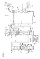
- the CO 2 recovery system A of the present embodiment includes a quencher (a pre-treatment apparatus) 2 that receives an exhaust gas 1 generated by burning coal or the like in a boiler, cools this exhaust gas 1, and removes gasified harmful substances (impurities) such as sulfur compounds in the exhaust gas 1; an absorber (an absorption apparatus) 4 that receives the exhaust gas 1 treated by the quencher 2 and brings the exhaust gas 1 into contact with a CO 2 absorption liquid (lean solvent) 3 to remove CO 2 from the exhaust gas 1; and a regenerator (a regeneration apparatus) 6 that receives and heats the CO 2 absorption liquid (rich solvent) 5 having absorbed CO 2 in the absorber 4 and separates and recovers CO 2 absorbed into the CO 2 absorption liquid 5, as shown in FIG. 1 .
- a quencher a pre-treatment apparatus
- an absorber an absorption apparatus 4 that receives the exhaust gas 1 treated by the quencher 2 and brings the exhaust gas 1 into contact with a CO 2 absorption liquid (lean solvent) 3 to remove CO 2
- the exhaust gas 1 from the boiler is introduced into a lower part and circulated from the lower part to an upper part, and the treated exhaust gas 1 is supplied to the absorber 4 through a communication duct 8 connected to the upper part.
- the quencher 2 includes a washing scrubber (a scrubber) 10. Washing water is sprayed from the upper part to the inside of the quencher 2 in a mist form by a pump, and this washing water and the exhaust gas 1 are brought into contact with each other. Accordingly, gaseous harmful substances or the like in the exhaust gas 1 are dissolved in the washing water and trapped. Further, the washing water W1 having trapped the harmful substances or the like falls to the lower part of the quencher 2 and is accumulated. Further, in the quencher 2, the washing water W1 accumulated in the lower part is pumped up by a pump and sprayed by the washing scrubber, and the exhaust gas 1 is pre-treated while circulating the washing water W1.
- a condenser 10a that cools the water sprayed by the washing scrubber 10 is provided.
- the washing water W1 is cooled by the condenser 10a and the exhaust gas 1 is brought into contact with this washing water W1 so that a temperature of the exhaust gas 1 is equal to or lower than a predetermined temperature.
- a demister 11 is provided above the washing scrubber 10. The exhaust gas 1 treated by the washing scrubber 10 passes through the demister 11, thereby condensate water or the like of the exhaust gas is removed.
- the exhaust gas 1 pre-treated by the quencher 2 is introduced into a lower part through the communication duct 8, flows from the lower part to an upper part, and is brought into contact with the CO 2 absorption liquid 3. Accordingly, CO 2 in the exhaust gas is removed, and the exhaust gas 1 from which CO 2 has been removed is exhausted as a treated gas from the upper part to the outside.
- an absorption liquid scrubber 12 that sprays the CO 2 absorption liquid (amine-based CO 2 absorption liquid) 3 is provided in the absorber 2 of the present embodiment.
- the CO 2 absorption liquid 3 sprayed from the absorption liquid scrubber 12 and the exhaust gas 1 flowing from the lower part to the upper part are brought into contact with each other. Accordingly, CO 2 in the exhaust gas 1 is dissolved in the CO 2 absorption liquid 3 and removed. Further, the CO 2 absorption liquid 5 having absorbed CO 2 is accumulated in the lower part of the absorber 4.
- an amine-based absorption liquid may be adopted as the CO 2 absorption liquid.
- an alkanolamine such as monoethanolamine, diethanolamine, triethanolamine, methyldiethanolamine, diisopropanolamine, or diglycolamine may be adopted as the CO 2 absorption liquid.
- hindered amines may be adopted.
- each water solution of the material or a water solution obtained by mixing two or more of the materials may be used as the CO 2 absorption liquid.
- a washing scrubber 13 that sprays the washing water cooled by the condenser and a pump are provided above the absorption liquid scrubber 12. Accordingly, impurities (containing harmful substances) in the exhaust gas 1 which have not been absorbed by the CO 2 absorption liquid 3 are trapped and removed by the washing water.
- a pair of demisters 14 and 15 is provided above the absorption liquid scrubber 12 and below the washing scrubber 13 at intervals in a vertical direction. Condensate water or the like in the exhaust gas 1 is removed by the demisters 14 and 15. Accordingly, a more reliably cleaned exhaust gas 1 is exhausted to the outside.
- an absorption liquid transportation pipe 7a for supplying the CO 2 absorption liquid 5 accumulated in the lower part to the regenerator 6 is connected to the lower part, and a liquid supply pump is provided in the absorption liquid transportation pipe 7a.
- an absorption liquid supply pipe 7b that supplies the CO 2 absorption liquid 3 to the absorption liquid scrubber 12 is connected to the absorber 4.
- an absorption liquid circulation path 7 through which the CO 2 absorption liquids 3 and 5 are circulated is formed of the absorption liquid transportation pipe 7a, the absorption liquid supply pipe 7b, the inside of the absorber 4, and the inside of the regenerator 6.
- the regenerator 6 separates and recovers CO 2 from the CO 2 absorption liquid 5 that has absorbed CO 2 or the like in the absorber 4.
- the absorption liquid transportation pipe 7a for introducing the CO 2 absorption liquid 5 from the absorber 4 is connected to an upper part of the regenerator 6. Also, the CO 2 absorption liquid 5 accumulated in the lower part of the absorber 4 is sprayed and supplied from the upper part side to the inside of the regenerator 6 by driving the liquid transportation pump of the absorption liquid transportation pipe 7a.
- dissociated CO 2 is cooled in the condenser 17, compressed in the CO 2 compressor 18, and treated. Condensate water generated by treating CO 2 in this way is returned to the regenerator 6. Meanwhile, the CO 2 absorption liquid 3 from which CO 2 has been dissociated and removed is accumulated in the lower part of the regenerator 6, and is sent to the absorber 4 by driving a return pump provided in the absorption liquid supply pipe 7b. Further, in this case, the CO 2 absorption liquid 3 is cooled in the condenser 7c, supplied to the absorber 4, sprayed from the absorption liquid scrubber 12 to absorb CO 2 again, and accumulated in the lower part of the absorber 4.
- harmful impurities (harmful substances) contained in the exhaust gas 1 may not be removed either in the quencher 2 or in the absorber 4 but may be brought into contact with the CO 2 absorption liquid 3 and dissolved in the CO 2 absorption liquid 3.
- impurities include selenium, arsenic, cadmium, lead, hexavalent chromium, mercury, copper, fluorine, and boron.
- harmful impurities, particularly selenium are not removed either in the quencher 2 or in the absorber 4 and are easily dissolved in the CO 2 absorption liquids 3 and 5.
- the concentration of the impurities is gradually increased by circulating the CO 2 absorption liquids 3 and 5 between the absorber 4 and the regenerator 6.
- an impurity removal unit 20 for removing harmful impurities in the exhaust gas 1 is included.
- the impurity removal unit 20 of the present embodiment includes a wet electrostatic precipitator 21 embedded above the demister 11 of the quencher 2, i.e., a top part of the quencher 2.
- the electrostatic precipitator 21 when the electrostatic precipitator 21 is provided in this way, dust (dust containing solid harmful impurities; solid) in the exhaust gas 1 supplied to the quencher 2 is trapped by the electrostatic precipitator 21. Accordingly, the harmful impurities such as solid selenium are removed from the exhaust gas 1 by the electrostatic precipitator 21, and the exhaust gas 1 containing no harmful impurities such as solid selenium or having a reduced content of the harmful impurities is supplied from the quencher 2 to the absorber 4 through the communication duct 8. Accordingly, when the CO 2 absorption liquid 3 is brought into contact with the exhaust gas 1, the harmful impurities such as selenium as well as CO 2 are not captured and dissolved in the CO 2 absorption liquids 3 and 5.
- the impurity removal unit 20 of the present embodiment includes an exhaust water treatment apparatus 22 that appropriately exhausts the washing water W1 accumulated in the lower part of the quencher 2, and adjusts pH or adds an inorganic coagulant such as ferric chloride or polyferric sulfate or a polymer coagulant such as PAC to coagulate, sediment and treat harmful substances contained in the washing water W1.Further, in this case, it is possible to use the CO 2 recovered in the CO 2 recovery system A when pH of the washing water W1 of a treatment target is adjusted.
- an inorganic coagulant such as ferric chloride or polyferric sulfate or a polymer coagulant such as PAC
- the harmful impurities can be recovered from the exhaust gas 1 before the exhaust gas 1 is supplied from the quencher 2 to the absorber 4, and the harmful impurities such as selenium can be prevented from having a high concentration in the CO 2 absorption liquids 3 and 5.
- the CO 2 recovery system A and the CO 2 recovery method of the present embodiment it is possible to remove, from the exhaust gas 1, the impurities such as selenium dissolved in the CO 2 absorption liquid 3 and having a high concentration in the absorption liquid circulation path 7 by the electrostatic precipitator 21 or the exhaust water treatment apparatus 22 of the impurity removal unit 20 in the quencher (pre-treatment apparatus) 2 in advance even when the removal of CO 2 from the exhaust gas 1 and the recovery (regeneration) of CO 2 from the CO 2 absorption liquid 5 are performed while circulating the CO 2 absorption liquids 3 and 5 between the absorber 4 and the regenerator 6 through the absorption liquid circulation path 7.
- the CO 2 recovery system A and the CO 2 recovery method of the present embodiment can prevent harmful impurities such as selenium from being dissolved in the CO 2 absorption liquids 3 and 5 and having a high concentration, unlike the related art. Further, it is possible to reduce the workload and cost required, for example, to treat waste generated accompanying the operation of the CO 2 recovery system A, exchange of the CO 2 absorption liquids 3 and 5, and maintenance of various apparatuses (each tower).
- the CO 2 recovery system of the present embodiment is configured similarly to that of the first embodiment except for the impurity removal unit. Accordingly, in the present embodiment, the same components as those in the first embodiment are denoted by the same reference numerals and a detailed description thereof will be omitted.
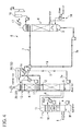
- the CO 2 recovery system A of the present embodiment includes a quencher 2 that receives an exhaust gas 1 generated by burning coal or the like in a boiler, cools this exhaust gas 1, and removes impurities such as sulfur compounds in the exhaust gas 1, an absorber 4 that receives the exhaust gas 1 treated in the quencher 2 and brings this exhaust gas 1 into contact with the CO 2 absorption liquid 3 to remove CO 2 , and a regenerator 6 that receives the CO 2 absorption liquid 5 that has absorbed CO 2 in the absorber 4 and separates and recovers CO 2 absorbed into the CO 2 absorption liquid 5, similar to the first embodiment, as shown in FIG. 2 .
- the CO 2 recovery system A of the present embodiment includes an impurity removal demister 23 disposed above a washing scrubber 10 of the quencher 2 as an impurity removal unit 20.
- the impurity removal demister 23 is formed of a wire material of a metal or a plastic in a mesh form (a filter form), and it is preferable to use, for example, a demister by which impurities having an average particle diameter of about 1.0 ⁇ m can be trapped according to impurities to be removed. Further, the demister may have a two-layer structure.
- the impurity removal demister 23 by including the impurity removal demister 23 in the quencher 2, dust (dust containing solid harmful impurities) in the exhaust gas 1 supplied to the quencher 2 is trapped by the impurity removal demister 23. Further, the impurities trapped by the impurity removal demister 23 fall to the lower part of the quencher 2 together with water drops. Accordingly, the harmful impurities such as selenium are not contained in the exhaust gas 1 supplied from the quencher 2 to the absorber 4 through the communication duct 8 or content thereof is reduced.
- the impurity removal unit 20 of the present embodiment includes an exhaust water treatment apparatus 22 that appropriately exhausts the washing water W1 accumulated in the lower part of the quencher 2 and coagulates, sediments and treats the harmful substances contained in the washing water W1. Accordingly, the impurities trapped by the impurity removal demister 23, falling to the lower part of the quencher 2 together with water drops and accumulated in the washing water W1 are reliably recovered and removed in the exhaust water treatment apparatus 22.
- the impurities such as selenium dissolved in the CO 2 absorption liquid 3 and having a high concentration in the absorption liquid circulation path 7 by the impurity removal demister 23 and the exhaust water treatment apparatus 22 of the impurity removal unit 20, in the quencher 2 in advance, even when the removal of coy from the exhaust gas 1 and recovery (regeneration) of CO 2 from the CO 2 absorption liquid 5 are performed while circulating the CO 2 absorption liquids 3 and 5 between the absorber 4 and the regenerator 6 through the absorption liquid circulation path 7, similar to the first embodiment.
- the CO 2 recovery system A and the CO 2 recovery method of the present embodiment it is possible to prevent the harmful impurities such as selenium from being dissolved in the CO 2 absorption liquids 3 and 5 and having a high concentration, unlike the related art. Further, it is possible to reduce the workload and cost required, for example, to treat waste generated accompanying the operation of the CO 2 recovery system A, exchange of the CO 2 absorption liquids 3 and 5, and maintenance of various apparatuses (each tower).
- the CO 2 recovery system of the present embodiment is configured similarly to those of the first and second embodiments except for the impurity removal unit. Accordingly, in the present embodiment, the same components as those in the first and second embodiments are denoted by the same reference numerals and a detailed description thereof will be omitted.
- the CO 2 recovery system A of the present embodiment includes a quencher 2 that cools an exhaust gas 1 and removes impurities such as sulfur compounds in the exhaust gas 1, an absorber 4 that brings the exhaust gas 1 treated by the quencher 2 into contact with a CO 2 absorption liquid 3 to remove CO 2 , and a regenerator 6 that receives the CO 2 absorption liquid 5 that has absorbed CO 2 in the absorber 4 and separates and recovers CO 2 absorbed into the CO 2 absorption liquid 5, similar to the first and second embodiments, as shown in FIG. 3 .
- a filtering apparatus 24 is provided as the impurity removal unit 20 in an absorption liquid transportation pipe 7a of an absorption liquid circulation path 7 that sends the CO 2 absorption liquid 5 having absorbed CO 2 from the absorber 4 to the regenerator 6.
- the CO 2 absorption liquid (rich solvent) 5 flowing in the absorption liquid transportation pipe 7a is filtered in the filtering apparatus 24 before the CO 2 absorption liquid is sent to the regenerator 6.
- the filtering apparatus 24 of the impurity removal unit 20 in the absorption liquid circulation path 7 even when the removal of CO 2 from the exhaust gas 1 and recovery (regeneration) of CO 2 from the CO 2 absorption liquid 5 are performed while circulating the CO 2 absorption liquids 3 and 5 between the absorber 4 and the regenerator 6 through the absorption liquid circulation path 7.
- the CO 2 recovery system A and the CO 2 recovery method of the present embodiment can prevent harmful impurities such as selenium from being dissolved in the CO 2 absorption liquids 3 and 5 and having a high concentration, unlike the related art. Further, it is possible to reduce the workload and cost required, for example, to treat waste generated accompanying the operation of the CO 2 recovery system A, exchange of the CO 2 absorption liquids 3 and 5, and maintenance of various apparatuses (each tower).
- the CO 2 recovery system of the present embodiment is configured similar to those of the first to third embodiments except for the impurity removal unit. Accordingly, in the present embodiment, the same components as those in the first to third embodiments are denoted by the same reference numerals and a detailed description thereof will be omitted.
- a CO 2 recovery system A of the present embodiment includes a quencher 2 that cools an exhaust gas 1 and removes impurities such as sulfur compounds in the exhaust gas 1, an absorber 4 that brings the exhaust gas 1 treated in the quencher 2 into contact with a CO 2 absorption liquid 3 to remove CO 2 , and a regenerator 6 that receives the CO 2 absorption liquid 5 that has absorbed CO 2 in the absorber 4 and separates and recovers CO 2 absorbed into the CO 2 absorption liquid 5, similar to the first to third embodiments, as shown in FIG. 4 .
- the CO 2 recovery system A of the present embodiment includes an impurity removal demister 25 disposed above a washing scrubber 10 of the quencher 2 as an impurity removal unit 20.
- the impurity removal demister 25 is formed of a wire material of a metal or a plastic in a mesh form (a filter form), and it is preferable to use, for example, a demister by which impurities having an average particle diameter of about 1.0 ⁇ m can be trapped according to impurities to be removed. Further, the demister may have a two-layer structure.
- the impurity removal unit 20 of the present embodiment includes a filtering apparatus 26 that filters the washing water sprayed in a washing scrubber 13 of the absorber 4 to remove harmful impurities contained in the washing water and returns the filtered washing water to a washing water circulation path 13a of the washing scrubber 13 of the absorber 4 and (or) an absorption liquid supply pipe 7b of an absorption liquid circulation path 7.
- the impurity removal demister 25 by including the impurity removal demister 25 above the washing scrubber 13 of the absorber 4, harmful impurities in the exhaust gas 1 supplied to the absorber 4 are trapped by the impurity removal demister 25. Further, the impurities trapped by the impurity removal demister 25 fall together with water drops and are accumulated in the washing water of the washing scrubber 13 of the absorber 4.
- the washing water of the washing scrubber 13 of the absorber 4 is filtered by the filtering apparatus 26, the impurities are recovered and removed. Further, the treated water filtered and cleaned by the filtering apparatus 26 is returned to the washing water circulation path 13a as washing water of the washing scrubber 13. And (or) this treated water is returned to the absorption liquid supply pipe 7b of the absorption liquid circulation path 7 and returned to the absorber 4 as the CO 2 absorption liquid (lean solvent) 3.
- the impurity removal demister 25 and the filtering apparatus 26 of the impurity removal unit 20 even when the removal of CO 2 from the exhaust gas 1 and the recovery (regeneration) of CO 2 from the CO 2 absorption liquid 5 are performed while circulating the CO 2 absorption liquids 3 and 5 between the absorber 4 and the regenerator 6 through the absorption liquid circulation path 7.
- the CO 2 recovery system A and the CO 2 recovery method of the present embodiment can prevent harmful impurities such as selenium from being dissolved in the CO 2 absorption liquids 3 and 5 and having a high concentration, unlike the related art. Further, it is possible to reduce the workload and cost required, for example, to treat waste generated accompanying the operation of the CO 2 recovery system A, exchange of the CO 2 absorption liquids 3 and 5, and maintenance of various apparatuses (each tower).
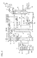
- a CO 2 recovery system A of the present embodiment includes a quencher 2 that cools an exhaust gas 1 and removes impurities such as sulfur compounds in the exhaust gas 1, an absorber 4 that brings the exhaust gas 1 treated by the quencher 2 into contact with the CO 2 absorption liquid 3 to remove CO 2 , and a regenerator 6 that receives the CO 2 absorption liquid 5 that has absorbed CO 2 in the absorber 4 and separates and recovers CO 2 absorbed into the CO 2 absorption liquid 5, similar to the first to fourth embodiments as shown in FIG. 5 .
- SO X or the like when SO X or the like is not removed in the quencher 2 but remains in the exhaust gas 1, SO X or the like may react to an alkanolamine contained in the CO 2 absorption liquid 5 in the regenerator 6 to generate a thermostable salt or when SO X or the like is brought into contact with the CO 2 absorption liquid 3 in the absorber 4, amine may deteriorate due to oxygen to generate a thermostable salt.
- the thermostable salt may be contained in the CO 2 absorption liquids 3 and 5.
- an absorption liquid drawing path 7d is branched and provided from an absorption liquid supply pipe 7b of an absorption liquid circulation path 7 that supplies CO 2 absorption liquid (lean solvent) 3 from the regenerator 6 to the absorber 4.
- the CO 2 recovery system A includes, as an impurity removal unit 20, a reclaimer 27 that draws the CO 2 absorption liquid 3 from the absorption liquid circulation path 7 through the absorption liquid drawing path 7d, heats the CO 2 absorption liquid 3, for example, at 130 to 150 °C using steam, and heats and concentrates impurities remaining in the CO 2 absorption liquid 3.
- the CO 2 absorption liquid 3 is treated in the reclaimer 27, the CO 2 absorption liquid 3 is separated into concentrated residue 28 and condensate water 29.
- the condensate water 29 is returned to the regenerator 6 and used as the CO 2 absorption liquid 3, and the concentrated residue 28 is exhausted from a waste discharge line to the outside, for example, using a pump, and treated.
- the impurity removal unit 20 of the present embodiment includes a first ion-exchange apparatus 30 that treats, using an ion-exchange resin, the CO 2 absorption liquid 3 of the absorption liquid circulation path 7 of the absorber 4 side rather than a branch part of the absorption liquid drawing path 7d of the absorption liquid supply pipe 7b.
- the impurity removal unit 20 includes a second ion-exchange apparatus 31 that treats the CO 2 absorption liquid 3 of the absorption liquid drawing path 7d using an ion-exchange resin.
- the first ion-exchange apparatus 30 and the second ion-exchange apparatus 31 include an anion-based ion-exchange resin.
- the CO 2 recovery system A and the CO 2 recovery method of the present embodiment first, it is possible to separate the condensate water 29 and the concentrated residue 28 by drawing the CO 2 absorption liquid 3 through the absorption liquid drawing path 7d and treating the CO 2 absorption liquid 3 in the reclaimer 27, and to remove harmful impurities and impurities causing the thermostable salt by exhausting the concentrated residue 28 to the outside of the system.
- the ion-exchange resin of the first ion-exchange apparatus 30 and the second ion-exchange apparatus 31 can be used while being appropriately regenerated at an ion-exchange resin regeneration factory. Accordingly, it is possible to reduce an amount of the waste, or it becomes unnecessary to dispose the resin as waste.
- the CO 2 recovery system A and the CO 2 recovery method of the present embodiment it is possible to remove the impurities in the exhaust gas 1 by the reclaimer 27, the first ion-exchange apparatus 30, and the second ion-exchange apparatus 31 of the impurity removal unit 20 even when the removal of CO 2 from the exhaust gas 1 and the recovery (regeneration) of CO 2 from the CO 2 absorption liquid 5 are performed while circulating the CO 2 absorption liquids 3 and 5 between the absorber 4 and the regenerator 6 through the absorption liquid circulation path 7.
- the CO 2 recovery system A and the CO 2 recovery method of the present embodiment can prevent harmful impurities such as selenium from being dissolved in the CO 2 absorption liquids 3 and 5 and having a high concentration, unlike the related art. Further, it is possible to reduce the workload and cost required, for example, to treat waste generated accompanying the operation of the CO 2 recovery system A, exchange of the CO 2 absorption liquids 3 and 5, and maintenance of various apparatuses (each tower).
- an impurity concentration in the reclaimer 27 is lowered by including the second ion-exchange apparatus 31, it is possible to increase a concentrating effect (concentrating magnification) of the reclaimer 27 and to improve efficiency of the reclaiming operation, i.e., increase throughput each time by the reclaimer 27.
- FIGS. 6 and 7 a CO 2 recovery system and a CO 2 recovery method according to a sixth embodiment of the present invention will be described with reference to FIGS. 6 and 7 .
- the same components as those in the first to fifth embodiments are denoted by the same reference numerals and a detailed description thereof will be omitted.
- a CO 2 recovery system A of the present embodiment includes a quencher 2 that cools an exhaust gas 1 and removes impurities such as sulfur compounds in the exhaust gas 1, an absorber 4 that brings the exhaust gas 1 treated by the quencher 2 into contact with a CO 2 absorption liquid 3 to remove CO 2 , and a regenerator 6 that receives the CO 2 absorption liquid 5 that has absorbed CO 2 in the absorber 4 and separates and removes CO 2 absorbed into the CO 2 absorption liquid 5, similar to the first to fourth embodiments, as shown in FIG. 6 .
- a first absorption liquid drawing path 7d is branched and provided from an absorption liquid supply pipe 7b of an absorption liquid circulation path 7 that supplies CO 2 absorption liquid (lean solvent) 3 from the regenerator 6 to the absorber 4, similar to the fifth embodiment, as shown in FIG. 6 .
- a reclaimer 27 that draws the CO 2 absorption liquid 3 from the absorption liquid circulation path 7 through the first absorption liquid drawing path 7d, heats the CO 2 absorption liquid 3, for example, at 130 to 150 °C using steam, and heats and concentrates impurities remaining in the CO 2 absorption liquid 3 is included as an impurity removal unit 20.
- a second absorption liquid drawing path 7e is branched and provided from an absorption liquid transportation pipe 7a of an absorption liquid circulation path 7 that supplies the CO 2 absorption liquid (rich solvent) 5 from the absorber 4 to the regenerator 6. Further, this second absorption liquid drawing path 7e is also connected to the reclaimer 27 to draw the CO 2 absorption liquid 5 from the absorption liquid circulation path 7, and the CO 2 absorption liquid 5 is heated in the reclaimer 27 to heat and concentrate impurities remaining in the CO 2 absorption liquid 5.
- the impurity removal unit 20 of the present embodiment includes a coagulation sedimentation treatment apparatus 32 that coagulates and sediments the CO 2 absorption liquids 3 and 5 of the first absorption liquid drawing path 7d and/or the second absorption liquid drawing path 7e to remove the impurities.
- the coagulation sedimentation treatment apparatus 32 includes, for example, a plurality of treatment tanks such as a pH adjustment tank 32a, a coagulant addition tank 32b, a stirring tank 32c, and a sedimentation tank 32d, as shown in FIG. 7 . Further, the pH adjustment tank 32a receives the CO 2 absorption liquids 3 and 5 and adjusts the CO 2 absorption liquids 3 and 5 to have pH suitable for the coagulation sedimentation of impurities, for example, using CO 2 recovered in the regenerator 6. In this case, surplus CO 2 is returned to the regenerator 6.
- a pH adjustment tank 32a receives the CO 2 absorption liquids 3 and 5 and adjusts the CO 2 absorption liquids 3 and 5 to have pH suitable for the coagulation sedimentation of impurities, for example, using CO 2 recovered in the regenerator 6. In this case, surplus CO 2 is returned to the regenerator 6.
- a coagulant of an inorganic coagulant such as ferric chloride or polyferric sulfate or an organic coagulant such as PAC is added in the coagulant addition tank 32b and stirred in the stirring tank 32c to coagulate the impurities, the impurities are sedimented in the sedimentation tank 32d, and a sediment is exhausted to the outside of the system. Further, supernatant treated water is supplied to the reclaimer 27.
- the treated water treated by the coagulation sedimentation treatment apparatus 32 through the first absorption liquid drawing path 7d and the second absorption liquid drawing path 7e is treated by the reclaimer 27, and accordingly, even when the coagulant remains, the coagulant is exhausted as concentrated residue 28 from the reclaimer 27.
- the CO 2 absorption liquid 3 and the CO 2 absorption liquid 5 may be drawn through the first absorption liquid drawing path 7d and the second absorption liquid drawing path 7e and supplied to the reclaimer 27 to be separated into the condensate water 29 and the concentrated residue 28, instead of being treated by the coagulation sedimentation treatment apparatus 32.
- the CO 2 recovery system A and the CO 2 recovery method of the present embodiment first, it is possible to separate the CO 2 absorption liquids 3 and 5 into the condensate water 29 and the concentrated residue 28 by drawing the CO 2 absorption liquids 3 and 5 through the absorption liquid drawing path 7d and the second absorption liquid drawing path 7e and treating the CO 2 absorption liquids 3 and 5 in the reclaimer 27, and to remove harmful impurities and impurities causing a thermostable salt by exhausting the concentrated residue 28 to the outside of the system.
- the CO 2 recovery system A and the CO 2 recovery method of the present embodiment it is possible to remove the impurities in the exhaust gas 1 by the reclaimer 27 and the coagulation sedimentation treatment apparatus 32 of the impurity removal unit 20 even when the removal of CO 2 from the exhaust gas 1 and recovery (regeneration) of CO 2 from the CO 2 absorption liquid 5 are performed while circulating the CO 2 absorption liquids 3 and 5 between the absorber 4 and the regenerator 6 through the absorption liquid circulation path 7.
- the CO 2 recovery system A and the CO 2 recovery method of the present embodiment can prevent harmful impurities such as selenium from being dissolved in the CO 2 absorption liquids 3 and 5 and having a high concentration, unlike the related art. Further, it is possible to reduce the workload and cost required, for example, to treat waste generated accompanying the operation of the CO 2 recovery system A, exchange of the CO 2 absorption liquids 3 and 5, and maintenance of various apparatuses (each tower).
- an impurity concentration in the reclaimer 27 is greatly lowered by including the coagulation sedimentation treatment apparatus 32, it is possible to increase a concentrating effect (concentrating magnification) of the reclaimer 27 and to improve efficiency of the reclaiming operation, i.e., increase throughput each time by the reclaimer 27.
- the CO 2 recovery system A when configured by including the reclaimer 27, the CO 2 recovery system A (the impurity recovery unit 20) may not necessarily be configured as in the fifth embodiment and the sixth embodiment.
- an incinerator (an incinerating apparatus) 35 that incinerates concentrated residue (reclaimed liquid; sludge) 28 generated in the reclaimer 27 may be included as the impurity recovery unit 20.
- the concentrated residue 28 when the concentrated residue 28 is incinerated in the incinerator 35, exhaust heat thereof may be recovered to generate steam and this steam may be reused, for example, as steam of the regenerator 6 and steam of the reclaimer 27. Accordingly, it is possible to obtain the same operational effect as that in the fifth embodiment and the sixth embodiment and to further improve energy efficiency.
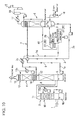
- a third ion-exchange apparatus 36 that performs ion-exchanging and treats concentrated residue 28 generated in the reclaimer 27 may be included as the impurity recovery unit 20.
- the third ion-exchange apparatus 36 is configured similar to the first ion-exchange apparatus 30 and the second ion-exchange apparatus 31.
- a harmful substance concentration of the concentrated residue 28 exhausted from the reclaimer 27, and thus the waste can be reduced by the treatment in the third ion-exchange apparatus 36. Since the harmful substance concentration of the waste is lowered in this way, it becomes possible to make a treatment of the concentrated residue 28 as industrial waste unnecessary, and it is possible to achieve volume reduction of the waste and reduction of treatment cost of the waste. Further, it is possible to further reduce the waste by regenerating an ion-exchange resin of the third ion-exchange apparatus 36 at an ion-exchange resin regeneration factory.
- a coagulation sedimentation treatment apparatus 37 that coagulates and sediments the concentrated residue 28 generated in the reclaimer 27 may be included as the impurity recovery unit 20, as shown in FIG. 10 .
- the coagulation sedimentation treatment apparatus 37 may be configured similar to the coagulation sedimentation treatment apparatus 32. Further, it is possible to reduce a harmful substance concentration of the concentrated residue 28 exhausted from the reclaimer 27, and thus the waste, by treatment in the coagulation sedimentation treatment apparatus 37. By lowering the harmful substance concentration of the waste in this way, it becomes possible to make a treatment of the concentrated residue 28 as industrial waste unnecessary, and it is possible to achieve volume reduction of the waste, reduction of the treatment cost of the waste, and the like. Further, it is possible to reduce an exhaust water amount and to perform the recovery of amines contained in the CO 2 absorption liquid 3 by returning the treated water from the coagulation sedimentation treatment apparatus 37 to the reclaimer 27 and reclaiming the treated water again.
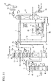
- an electrodialysis treatment apparatus 38 that performs electrodialysis on the concentrated residue 28 generated in the reclaimer 27 may be included as the impurity recovery unit 20, as shown in FIG. 11 .
- an acid solution is added to the concentrated residue 28 in advance to ionize harmful impurities.
- the concentrated residue (reclaimed liquid; sludge) 28 after treatment in the normal first reclaimer 27 shown in FIGS. 5 to 11 may be treated in the second reclaimer 39 of the impurity removal unit 20, as shown in FIG. 12 .
- NaOH is added to the concentrated residue 28 at the time of treatment in the second reclaimer 39 and a generation amount of Na 2 CO 3 due to a reaction of CO 2 in the CO 2 absorption liquid 3 and a reflux liquid 40 to NaOH is reduced to improve an amine recovery effect due to NaOH.
- the generation amount of Na 2 CO 3 is reduced, it is possible to minimize elevation of a boiling point and to increase a reclaiming throughput.
- a vacuum reclaiming path 45 disposed by connecting a condenser 41, a gas and liquid separation apparatus 42, and a blower (a vacuum fan) 43 in series with the second reclaimer 39 is included.
- a blower a vacuum fan
- a return path 46 that returns condensate water 29 separated in one reclaimer 27 to the regenerator 6 may be provided and a vacuum reclaiming path 47 may be provided by connecting a condenser 41, a gas and liquid separation apparatus 42, and a blower (a vacuum fan) 43 in series with the reclaimer 27 so that one reclaimer 27 may be used in two operations of a first operation manipulation and a second operation manipulation.
- a CO 2 absorption liquid (lean solvent) 3 is drawn from the regenerator 6, and the CO 2 absorption liquid 3 is heated, for example, at 130 to 150 °C to separate concentrated residue 28 and condensate water 29 from the CO 2 absorption liquid 3.
- the concentrated residue 28 is exhausted from a waste discharge line to the outside using a pump and treated, and the separated condensate water 29 is returned to the regenerator 6.
- a generation amount of Na 2 CO 3 generated by adding NaOH at the time of treatment in the reclaimer 27 and causing CO 2 in the CO 2 absorption liquid (lean solvent) 3 and a reflux liquid 40 to react to NaOH is reduced to improve an amine recovery effect by NaOH.
- the generation amount of Na 2 CO 3 it is possible to minimize elevation of a boiling point and increase a reclaiming throughput. Further, it is possible to further increase an amine recovery amount by causing the treatment in the reclaimer 27 to be vacuum reclaiming.
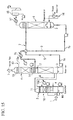
- harmful impurities may be recovered and removed from the CO 2 absorption liquid 3 by treating the concentrated residue (reclaimed liquid; sludge) 28 after treatment in the reclaimer 27, in the evaporation and concentration apparatus 44 of the impurity removal unit 20, as shown in FIG. 14 .
- steam evaporated in the evaporation and concentration apparatus 44 is separated in the gas and liquid separation apparatus 45, condensate water 46 is returned to the absorber 4, and a gas 47 is returned to an entrance side of the quencher 2. Accordingly, it is possible to remove the harmful impurities, which have been vaporized in the evaporation and concentration apparatus 44, in the quencher 2 again. Further, it is possible to reduce the harmful substance concentration of the waste exhausted from the reclaimer 27 and it becomes possible to make a treatment of waste as industrial waste unnecessary. Thus, it is possible to achieve volume reduction of the waste and reduction of waste treatment cost.
- the CO 2 recovery system and the CO 2 recovery method described above it is possible to prevent the harmful substances (impurities) such as selenium from being dissolved in the CO 2 absorption liquid and having a high concentration, unlike the related art.
Landscapes
- Chemical & Material Sciences (AREA)
- Engineering & Computer Science (AREA)
- Analytical Chemistry (AREA)
- General Chemical & Material Sciences (AREA)
- Oil, Petroleum & Natural Gas (AREA)
- Chemical Kinetics & Catalysis (AREA)
- Treating Waste Gases (AREA)
- Gas Separation By Absorption (AREA)
- Vaporization, Distillation, Condensation, Sublimation, And Cold Traps (AREA)
- Separation Of Suspended Particles By Flocculating Agents (AREA)
- Electrostatic Separation (AREA)
- Treatment Of Water By Ion Exchange (AREA)
- Heat Treatment Of Water, Waste Water Or Sewage (AREA)
- Water Treatment By Electricity Or Magnetism (AREA)
- Separation Using Semi-Permeable Membranes (AREA)
- Life Sciences & Earth Sciences (AREA)
- Sustainable Development (AREA)
- Health & Medical Sciences (AREA)
- Biomedical Technology (AREA)
- Environmental & Geological Engineering (AREA)
Abstract
Description
- The present invention relates to a CO2 recovery system and a CO2 recovery method for recovering and removing CO2 from an exhaust gas.
- Priority is claimed on
U.S. Patent Application No. 13/784,173, filed on March 4, 2013 - Conventionally, in a thermal power plant or the like, for example, fossil fuel such as coal, oil, or LNG is burned in a boiler to generate steam, and power generation is performed by turning a turbine using this steam. Further, in such a thermal power plant or the like, since a large amount of exhaust gas containing CO2, which is one of the greenhouse gases contributing global warming, is exhausted with combustion of the fossil fuel, a facility for treating this exhaust gas, particularly, recovering and removing CO2 from the exhaust gas, is provided.
- Further, a system that recovers CO2 (a CO2 recovery apparatus) includes, for example, a quencher (a pre-treatment apparatus) 2 that performs pre-treatment of an
exhaust gas 1, an absorber (an absorption apparatus) 4 that brings the exhaust gas treated by thequencher 2 and having a low temperature into contact with a CO2 absorption liquid (lean solvent 3) to absorb and remove CO2 from theexhaust gas 1, and a regenerator (a regeneration apparatus) 6 that separates and recovers CO2 from the CO2 absorption liquid (rich solvent 5) having absorbed CO2 in theabsorber 4, as shown inFIG. 15 (e.g., seePatent Document 1 and Patent Document 2). - Further, the CO2 absorption liquid 3 after CO2 has been recovered in the
regenerator 6 is sent to theabsorber 4 and used to absorb and remove CO2 from theexhaust gas 1 again. In other words, this CO2 recovery system is configured to circulate the CO2 absorption liquids 3 and 5 in an absorptionliquid circulation path 7 between theabsorber 4 and theregenerator 6 and repeat the absorption of CO2 into the CO2 absorption liquid 3 and the recovery of CO2 from the CO2 absorption liquid 5 to recover and remove CO2 from theexhaust gas 1, which is sequentially supplied. -
- [Patent Document 1]
Japanese Unexamined Patent Application, First Publication No. 2011-036730 - [Patent Document 2]
Japanese Unexamined Patent Application, First Publication No. 2012-091083 - Here, heavy metals such as mercury, chromium, or cadmium, or harmful substances (impurities) such as selenium or arsenic are contained in a gaseous form (gas) or a fine particle form (solid) according to the quality of coal or the like in an exhaust gas generated with combustion of the coal or the like. Further, when an exhaust gas containing this kind of heavy metal or the like is treated in a CO2 recovery system, many harmful substances in the exhaust gas are removed in the quencher or the like, but particularly, some solid harmful substances may not be removed in the quencher or the like, may be sent to the absorber together with the exhaust gas, and may be dissolved in the CO2 absorption liquid.
- Further, in the CO2 recovery system of the related art described above, a problem arises in that the harmful substances in the CO2 absorption liquid have a gradually higher concentration since the CO2 absorption liquid is circulated and used between the absorber and the regenerator. Particularly, it was confirmed that selenium has a high concentration in the CO2 absorption liquid. There is a great need for a scheme for removing harmful substances (impurities) including selenium from the CO2 absorption liquid.
- According to a first aspect of the present invention, a CO2 recovery system includes: a pre-treatment apparatus that cools an exhaust gas; an absorption apparatus that brings a CO2 absorption liquid into contact with the exhaust gas treated by the pre-treatment apparatus so that CO2 in the exhaust gas is absorbed into the CO2 absorption liquid; a regeneration apparatus that receives the CO2 absorption liquid having absorbed CO2 from the absorption apparatus and heats the CO2 absorption liquid to separate CO2 from the CO2 absorption liquid; an absorption liquid circulation path that circulates the CO2 absorption liquid between the absorption apparatus and the regeneration apparatus; and an impurity removal unit that removes impurities dissolved in the CO2 absorption liquid from the exhaust gas and having a high concentration in the absorption liquid circulation path, in the absorption liquid circulation path and/or in the pre-treatment apparatus in advance.
- In the CO2 recovery system, the impurities may be substances containing at least one kind of selenium, arsenic, cadmium, lead, hexavalent chromium, mercury, copper, fluorine, and boron.
- In the CO2 recovery system, the impurity removal unit may include an electrostatic precipitator provided in the pre-treatment apparatus.
- In the CO2 recovery system, the impurity removal unit may include an impurity removal demister provided in the pre-treatment apparatus and/or the absorption apparatus.
- In the CO2 recovery system, the pre-treatment apparatus may include a scrubber, and the impurity removal unit may include an exhaust water treatment apparatus that treats washing water sprayed from the scrubber of the pre-treatment apparatus to remove impurities contained in the washing water.
- In the CO2 recovery system, the impurity removal unit may include a filtering apparatus that filters the CO2 absorption liquid supplied from the absorption apparatus to the regeneration apparatus of the absorption liquid circulation path and/or the CO2 absorption liquid supplied from the regeneration apparatus to the absorption apparatus of the absorption liquid circulation path to remove the impurities.
- In the CO2 recovery system, the absorption apparatus may include a scrubber, and the impurity removal unit may include a filtering apparatus that filters the washing water sprayed by the scrubber of the absorption apparatus to remove impurities contained in the washing water, and returns the filtered washing water to a washing water circulation path and/or the absorption liquid circulation path of the scrubber of the absorption apparatus.
- In the CO2 recovery system, the impurity removal unit may include an ion-exchange apparatus that brings the CO2 absorption liquid supplied from the absorption apparatus to the regeneration apparatus of the absorption liquid circulation path and/or the CO2 absorption liquid supplied from the regeneration apparatus to the absorption apparatus of the absorption liquid circulation path into contact with an ion-exchange resin to remove the impurities.
- In the CO2 recovery system, the impurity removal unit may include a reclaimer that draws and heats the CO2 absorption liquid of the absorption liquid circulation path, heats and concentrates impurities in the CO2 absorption liquid, and returns condensate water to the regeneration apparatus; and an ion-exchange apparatus that brings the CO2 absorption liquid of an absorption liquid drawing path that supplies the CO2 absorption liquid from the absorption liquid circulation path to the reclaimer into contact with an ion-exchange resin to remove the impurities.
- In the CO2 recovery system, the impurity removal unit may include a reclaimer that draws and heats the CO2 absorption liquid of the absorption liquid circulation path, heats and concentrates impurities in the CO2 absorption liquid, and returns condensate water to the regeneration apparatus; and a coagulation sedimentation treatment apparatus that coagulates and sediments the CO2 absorption liquid of an absorption liquid drawing path that supplies the CO2 absorption liquid from the absorption liquid circulation path to the reclaimer, to remove the impurities.
- In the CO2 recovery system, the coagulation sedimentation treatment apparatus may adjust pH of the CO2 absorption liquid using CO2 separated in the regeneration apparatus.
- In the CO2 recovery system, the impurity removal unit may include a reclaimer that draws and heats the CO2 absorption liquid of the absorption liquid circulation path, heats and concentrates impurities in the CO2 absorption liquid, and returns condensate water to the regeneration apparatus; and an incinerator that incinerates concentrated residue generated from the reclaimer, wherein steam may be generated using exhaust heat when the concentrated residue is incinerated in the incinerator, and the steam may be used in the reclaimer and/or the regeneration apparatus.
- In the CO2 recovery system, the impurity removal unit may include a reclaimer that draws and heats the CO2 absorption liquid of the absorption liquid circulation path, heats and concentrates impurities in the CO2 absorption liquid, and returns condensate water to the regeneration apparatus; and an ion-exchange apparatus that brings concentrated residue generated from the reclaimer into contact with an ion-exchange resin to remove the impurities.
- In the CO2 recovery system, the impurity removal unit may include a reclaimer that draws and heats the CO2 absorption liquid of the absorption liquid circulation path, heats and concentrates impurities in the CO2 absorption liquid, and returns condensate water to the regeneration apparatus, and a coagulation sedimentation treatment apparatus that coagulates and sediments concentrated residue generated from the reclaimer to remove the impurities.
- In the CO2 recovery system, the impurity removal unit may include a reclaimer that draws and heats the CO2 absorption liquid of the absorption liquid circulation path, heats and concentrates impurities in the CO2 absorption liquid, and returns condensate water to the regeneration apparatus; and an electrodialysis treatment apparatus that performs electrodialysis on concentrated residue generated from the reclaimer to remove the impurities.
- In the CO2 recovery system, the pre-treatment apparatus may include a scrubber, and acidic treated water generated by treatment in the electrodialysis treatment apparatus of the impurity removal unit may be supplied as cleaning water for acid cleaning of the scrubber of the pre-treatment apparatus.
- In the CO2 recovery system, the impurity removal unit may include a first reclaimer that draws and heats the CO2 absorption liquid of the absorption liquid circulation path, heats and concentrates impurities in the CO2 absorption liquid, and returns condensate water to the regeneration apparatus; and a second reclaimer that heats concentrated residue generated from the first reclaimer, further heats and concentrates the concentrated residue, and returns condensate water to the regeneration apparatus.
- In the CO2 recovery system, NaOH may be added to the concentrated residue at the time of treatment in the second reclaimer of the impurity removal unit.
- In the CO2 recovery system, the impurity removal unit may include a vacuum reclaiming path disposed by connecting a condenser, a gas and liquid separation apparatus, and a vacuum fan in series with the second reclaimer.
- In the CO2 recovery system, the impurity removal unit may include a first reclaimer that draws and heats the CO2 absorption liquid of the absorption liquid circulation path, heats and concentrates impurities in the CO2 absorption liquid, and returns condensate water to the regeneration apparatus; a condensate water return path that returns condensate water separated in the first reclaimer to the regeneration apparatus; and a vacuum reclaiming path disposed by connecting a condenser, a gas and liquid separation apparatus, and a vacuum fan in series with the first reclaimer.
- In the CO2 recovery system, the impurity removal unit may include a first reclaimer that draws and heats the CO2 absorption liquid of the absorption liquid circulation path, heats and concentrates impurities in the CO2 absorption liquid, and returns condensate water to the regeneration apparatus; an evaporation and concentration apparatus that heats concentrated residue generated from the first reclaimer to generate steam, and heats and concentrates the concentrated residue; and a gas and liquid separation apparatus that separates the steam generated from the evaporation and concentration apparatus into a gas and condensate water, and returns the gas to the pre-treatment apparatus and the condensate water to the absorption apparatus.
- According to a second aspect of the present invention, a CO2 recovery method includes cooling an exhaust gas by a pre-treatment apparatus; bringing, by an absorption apparatus, the exhaust gas treated by the pre-treatment apparatus into contact with a CO2 absorption liquid so that CO2 in the exhaust gas is absorbed into the CO2 absorption liquid; receiving the CO2 absorption liquid treated in the absorption apparatus and heating, by a regeneration apparatus, the CO2 absorption liquid to separate CO2 from the CO2 absorption liquid; circulating the CO2 absorption liquid between the absorption apparatus and the regeneration apparatus through an absorption liquid circulation path to perform removal of CO2 from the exhaust gas and recovery of CO2 from the CO2 absorption liquid; and removing, by an impurity removal unit, impurities dissolved in the CO2 absorption liquid and having a high concentration in the absorption liquid circulation path from the exhaust gas, in the absorption liquid circulation path and/or in the pre-treatment apparatus in advance.
- In the CO2 recovery system and the CO2 recovery method described above, it is possible to remove, from the exhaust gas, impurities that are dissolved in the CO2 absorption liquid and have a high concentration in the absorption liquid circulation path, using the impurity removal unit in the absorption liquid circulation path and/or the pre-treatment apparatus in advance even when the removal of CO2 from the exhaust gas and the recovery (regeneration) of CO2 from the CO2 absorption liquid are performed while circulating the CO2 absorption liquid between the absorption apparatus and the regeneration apparatus through the absorption liquid circulation path.
- Thus, according to the CO2 recovery system and the CO2 recovery method described above, it is possible to prevent harmful substances (impurities) such as selenium from being dissolved in the CO2 absorption liquid and having a high concentration, unlike the related art.
- Further, it is possible to reduce the work and cost required, for example, to treat waste generated accompanying the operation of the CO2 recovery system, exchange of the CO2 absorption liquid, and maintenance of various apparatuses.
-
-
FIG. 1 is a diagram illustrating a CO2 recovery system (a CO2 recovery method) according to a first embodiment of the present invention. -
FIG. 2 is a diagram illustrating a CO2 recovery system (a CO2 recovery method) according to a second embodiment of the present invention. -
FIG. 3 is a diagram illustrating a CO2 recovery system (a CO2 recovery method) according to a third embodiment of the present invention. -
FIG. 4 is a diagram illustrating a CO2 recovery system (a CO2 recovery method) according to a fourth embodiment of the present invention. -
FIG. 5 is a diagram illustrating a CO2 recovery system (a CO2 recovery method) according to a fifth embodiment of the present invention. -
FIG. 6 is a diagram illustrating a CO2 recovery system (a CO2 recovery method) according to a sixth embodiment of the present invention. -
FIG. 7 is a diagram illustrating a coagulation sedimentation treatment apparatus. -
FIG. 8 is a diagram illustrating a modified example of the CO2 recovery system (the CO2 recovery method) according to the fifth and sixth embodiments of the present invention. -
FIG. 9 is a diagram illustrating a modified example of the CO2 recovery system (the CO2 recovery method) according to the fifth and sixth embodiments of the present invention. -
FIG. 10 is a diagram illustrating a modified example of the CO2 recovery system (the CO2 recovery method) according to the fifth and sixth embodiments of the present invention. -
FIG. 11 is a diagram illustrating a modified example of the CO2 recovery system (the CO2 recovery method) according to the fifth and sixth embodiments of the present invention. -
FIG. 12 is a diagram illustrating a modified example of the CO2 recovery system (the CO2 recovery method) according to the fifth and sixth embodiments of the present invention. -
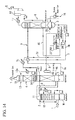
FIG. 13 is a diagram illustrating a modified example of the CO2 recovery system (the CO2 recovery method) according to the fifth and sixth embodiments of the present invention. -
FIG. 14 is a diagram illustrating a modified example of the CO2 recovery system (the CO2 recovery method) according to the fifth and sixth embodiments of the present invention. -
FIG. 15 is a diagram illustrating a CO2 recovery system (a CO2 recovery method) of the related art. - Hereinafter, a CO2 recovery system and a CO2 recovery method according to a first embodiment of the present invention will be described with reference to
FIG. 1 . Here, the CO2 recovery system and the CO2 recovery method of the present embodiment relate to a system for treating an exhaust gas from a boiler and a turbine burning a large amount of fossil fuel such as coal, oil, or LNG in a generation facility such as a thermal power plant, and recovering CO2 from this exhaust gas. Further, the CO2 recovery system and the CO2 recovery method according to the present embodiment need not be used for only treating the exhaust gas generated in thermal power plant, and may also be applied to other cases in which CO2 is recovered and removed from an exhaust gas. - The CO2 recovery system A of the present embodiment includes a quencher (a pre-treatment apparatus) 2 that receives an
exhaust gas 1 generated by burning coal or the like in a boiler, cools thisexhaust gas 1, and removes gasified harmful substances (impurities) such as sulfur compounds in theexhaust gas 1; an absorber (an absorption apparatus) 4 that receives theexhaust gas 1 treated by thequencher 2 and brings theexhaust gas 1 into contact with a CO2 absorption liquid (lean solvent) 3 to remove CO2 from theexhaust gas 1; and a regenerator (a regeneration apparatus) 6 that receives and heats the CO2 absorption liquid (rich solvent) 5 having absorbed CO2 in theabsorber 4 and separates and recovers CO2 absorbed into the CO2 absorption liquid 5, as shown inFIG. 1 . - Further, in the
quencher 2, theexhaust gas 1 from the boiler is introduced into a lower part and circulated from the lower part to an upper part, and the treatedexhaust gas 1 is supplied to theabsorber 4 through acommunication duct 8 connected to the upper part. Further, thequencher 2 includes a washing scrubber (a scrubber) 10. Washing water is sprayed from the upper part to the inside of thequencher 2 in a mist form by a pump, and this washing water and theexhaust gas 1 are brought into contact with each other. Accordingly, gaseous harmful substances or the like in theexhaust gas 1 are dissolved in the washing water and trapped. Further, the washing water W1 having trapped the harmful substances or the like falls to the lower part of thequencher 2 and is accumulated. Further, in thequencher 2, the washing water W1 accumulated in the lower part is pumped up by a pump and sprayed by the washing scrubber, and theexhaust gas 1 is pre-treated while circulating the washing water W1. - Further, a
condenser 10a that cools the water sprayed by thewashing scrubber 10 is provided. In order to increase efficiency when the CO2 absorption liquid 3 is brought into contact with theexhaust gas 1 to absorb and remove CO2 in theabsorber 4 of a subsequent stage, the washing water W1 is cooled by thecondenser 10a and theexhaust gas 1 is brought into contact with this washing water W1 so that a temperature of theexhaust gas 1 is equal to or lower than a predetermined temperature. Further, in thequencher 2, ademister 11 is provided above thewashing scrubber 10. Theexhaust gas 1 treated by thewashing scrubber 10 passes through thedemister 11, thereby condensate water or the like of the exhaust gas is removed. - In the
absorber 4, theexhaust gas 1 pre-treated by thequencher 2 is introduced into a lower part through thecommunication duct 8, flows from the lower part to an upper part, and is brought into contact with the CO2 absorption liquid 3. Accordingly, CO2 in the exhaust gas is removed, and theexhaust gas 1 from which CO2 has been removed is exhausted as a treated gas from the upper part to the outside. - Further, an
absorption liquid scrubber 12 that sprays the CO2 absorption liquid (amine-based CO2 absorption liquid) 3 is provided in theabsorber 2 of the present embodiment. The CO2 absorption liquid 3 sprayed from theabsorption liquid scrubber 12 and theexhaust gas 1 flowing from the lower part to the upper part are brought into contact with each other. Accordingly, CO2 in theexhaust gas 1 is dissolved in the CO2 absorption liquid 3 and removed. Further, the CO2 absorption liquid 5 having absorbed CO2 is accumulated in the lower part of theabsorber 4. - Here, for example, an amine-based absorption liquid may be adopted as the CO2 absorption liquid. Specifically, an alkanolamine such as monoethanolamine, diethanolamine, triethanolamine, methyldiethanolamine, diisopropanolamine, or diglycolamine may be adopted as the CO2 absorption liquid. Further, hindered amines may be adopted. Further, each water solution of the material or a water solution obtained by mixing two or more of the materials may be used as the CO2 absorption liquid.
- Further, in the
absorber 4, awashing scrubber 13 that sprays the washing water cooled by the condenser and a pump are provided above theabsorption liquid scrubber 12. Accordingly, impurities (containing harmful substances) in theexhaust gas 1 which have not been absorbed by the CO2 absorption liquid 3 are trapped and removed by the washing water. Further, a pair ofdemisters absorption liquid scrubber 12 and below thewashing scrubber 13 at intervals in a vertical direction. Condensate water or the like in theexhaust gas 1 is removed by the demisters 14 and 15. Accordingly, a more reliably cleanedexhaust gas 1 is exhausted to the outside. - Further, in the
absorber 4, an absorptionliquid transportation pipe 7a for supplying the CO2 absorption liquid 5 accumulated in the lower part to theregenerator 6 is connected to the lower part, and a liquid supply pump is provided in the absorptionliquid transportation pipe 7a. Further, an absorptionliquid supply pipe 7b that supplies the CO2 absorption liquid 3 to theabsorption liquid scrubber 12 is connected to theabsorber 4. Also, an absorptionliquid circulation path 7 through which the CO2 absorption liquids 3 and 5 are circulated is formed of the absorptionliquid transportation pipe 7a, the absorptionliquid supply pipe 7b, the inside of theabsorber 4, and the inside of theregenerator 6. - The
regenerator 6 separates and recovers CO2 from the CO2 absorption liquid 5 that has absorbed CO2 or the like in theabsorber 4. The absorptionliquid transportation pipe 7a for introducing the CO2 absorption liquid 5 from theabsorber 4 is connected to an upper part of theregenerator 6. Also, the CO2 absorption liquid 5 accumulated in the lower part of theabsorber 4 is sprayed and supplied from the upper part side to the inside of theregenerator 6 by driving the liquid transportation pump of the absorptionliquid transportation pipe 7a. - Further, high temperature steam is supplied from the lower part to the
regenerator 6 by thereboiler 16, and the sprayed CO2 absorption liquid 5 is heated. Accordingly, CO2 is dissociated from the CO2 absorption liquid 5 and gasified, and gasified CO2 is led out from the upper part of theregenerator 6 to the outside. - Further, dissociated CO2 is cooled in the
condenser 17, compressed in the CO2 compressor 18, and treated. Condensate water generated by treating CO2 in this way is returned to theregenerator 6. Meanwhile, the CO2 absorption liquid 3 from which CO2 has been dissociated and removed is accumulated in the lower part of theregenerator 6, and is sent to theabsorber 4 by driving a return pump provided in the absorptionliquid supply pipe 7b. Further, in this case, the CO2 absorption liquid 3 is cooled in thecondenser 7c, supplied to theabsorber 4, sprayed from theabsorption liquid scrubber 12 to absorb CO2 again, and accumulated in the lower part of theabsorber 4. - Meanwhile, harmful impurities (harmful substances) contained in the
exhaust gas 1 may not be removed either in thequencher 2 or in theabsorber 4 but may be brought into contact with the CO2 absorption liquid 3 and dissolved in the CO2 absorption liquid 3. Examples of such impurities include selenium, arsenic, cadmium, lead, hexavalent chromium, mercury, copper, fluorine, and boron. Further, such harmful impurities, particularly selenium, are not removed either in thequencher 2 or in theabsorber 4 and are easily dissolved in the CO2 absorption liquids 3 and 5. The concentration of the impurities is gradually increased by circulating the CO2 absorption liquids 3 and 5 between theabsorber 4 and theregenerator 6. - In contrast, in the CO2 recovery system (and the CO2 recovery method) of the present embodiment, an
impurity removal unit 20 for removing harmful impurities in theexhaust gas 1 is included. Further, theimpurity removal unit 20 of the present embodiment includes a wetelectrostatic precipitator 21 embedded above thedemister 11 of thequencher 2, i.e., a top part of thequencher 2. - Further, when the
electrostatic precipitator 21 is provided in this way, dust (dust containing solid harmful impurities; solid) in theexhaust gas 1 supplied to thequencher 2 is trapped by theelectrostatic precipitator 21. Accordingly, the harmful impurities such as solid selenium are removed from theexhaust gas 1 by theelectrostatic precipitator 21, and theexhaust gas 1 containing no harmful impurities such as solid selenium or having a reduced content of the harmful impurities is supplied from thequencher 2 to theabsorber 4 through thecommunication duct 8. Accordingly, when the CO2 absorption liquid 3 is brought into contact with theexhaust gas 1, the harmful impurities such as selenium as well as CO2 are not captured and dissolved in the CO2 absorption liquids 3 and 5. - Meanwhile, when the
electrostatic precipitator 21 is provided in thequencher 2 to trap dust including harmful impurities, harmful materials such as heavy metals are dissolved and contained even in the washing water sprayed by thewashing scrubber 10 and accumulated in the lower part of thequencher 2. - Accordingly, the
impurity removal unit 20 of the present embodiment includes an exhaustwater treatment apparatus 22 that appropriately exhausts the washing water W1 accumulated in the lower part of thequencher 2, and adjusts pH or adds an inorganic coagulant such as ferric chloride or polyferric sulfate or a polymer coagulant such as PAC to coagulate, sediment and treat harmful substances contained in the washing water W1.Further, in this case, it is possible to use the CO2 recovered in the CO2 recovery system A when pH of the washing water W1 of a treatment target is adjusted. Accordingly, the harmful impurities can be recovered from theexhaust gas 1 before theexhaust gas 1 is supplied from thequencher 2 to theabsorber 4, and the harmful impurities such as selenium can be prevented from having a high concentration in the CO2 absorption liquids 3 and 5. - Thus, in the CO2 recovery system A and the CO2 recovery method of the present embodiment, it is possible to remove, from the
exhaust gas 1, the impurities such as selenium dissolved in the CO2 absorption liquid 3 and having a high concentration in the absorptionliquid circulation path 7 by theelectrostatic precipitator 21 or the exhaustwater treatment apparatus 22 of theimpurity removal unit 20 in the quencher (pre-treatment apparatus) 2 in advance even when the removal of CO2 from theexhaust gas 1 and the recovery (regeneration) of CO2 from the CO2 absorption liquid 5 are performed while circulating the CO2 absorption liquids 3 and 5 between theabsorber 4 and theregenerator 6 through the absorptionliquid circulation path 7. - Accordingly, the CO2 recovery system A and the CO2 recovery method of the present embodiment can prevent harmful impurities such as selenium from being dissolved in the CO2 absorption liquids 3 and 5 and having a high concentration, unlike the related art. Further, it is possible to reduce the workload and cost required, for example, to treat waste generated accompanying the operation of the CO2 recovery system A, exchange of the CO2 absorption liquids 3 and 5, and maintenance of various apparatuses (each tower).
- Next, a CO2 recovery system and a CO2 recovery method according to a second embodiment of the present invention will be described with reference to
FIG. 2 . Here, the CO2 recovery system of the present embodiment is configured similarly to that of the first embodiment except for the impurity removal unit. Accordingly, in the present embodiment, the same components as those in the first embodiment are denoted by the same reference numerals and a detailed description thereof will be omitted. - The CO2 recovery system A of the present embodiment includes a
quencher 2 that receives anexhaust gas 1 generated by burning coal or the like in a boiler, cools thisexhaust gas 1, and removes impurities such as sulfur compounds in theexhaust gas 1, anabsorber 4 that receives theexhaust gas 1 treated in thequencher 2 and brings thisexhaust gas 1 into contact with the CO2 absorption liquid 3 to remove CO2, and aregenerator 6 that receives the CO2 absorption liquid 5 that has absorbed CO2 in theabsorber 4 and separates and recovers CO2 absorbed into the CO2 absorption liquid 5, similar to the first embodiment, as shown inFIG. 2 . - Meanwhile, the CO2 recovery system A of the present embodiment includes an
impurity removal demister 23 disposed above awashing scrubber 10 of thequencher 2 as animpurity removal unit 20. Theimpurity removal demister 23 is formed of a wire material of a metal or a plastic in a mesh form (a filter form), and it is preferable to use, for example, a demister by which impurities having an average particle diameter of about 1.0 µm can be trapped according to impurities to be removed. Further, the demister may have a two-layer structure. - Further, in the CO2 recovery system A and the CO2 recovery method of the present embodiment, by including the
impurity removal demister 23 in thequencher 2, dust (dust containing solid harmful impurities) in theexhaust gas 1 supplied to thequencher 2 is trapped by theimpurity removal demister 23. Further, the impurities trapped by theimpurity removal demister 23 fall to the lower part of thequencher 2 together with water drops. Accordingly, the harmful impurities such as selenium are not contained in theexhaust gas 1 supplied from thequencher 2 to theabsorber 4 through thecommunication duct 8 or content thereof is reduced. Thereby, when the CO2 absorption liquid 3 is brought into contact with theexhaust gas 1, the harmful impurities such as selenium as well as CO2 are not captured into the CO2 absorption liquid 3. Or, it becomes difficult for the harmful impurities such as selenium as well as CO2 to be captured. - Further, the
impurity removal unit 20 of the present embodiment includes an exhaustwater treatment apparatus 22 that appropriately exhausts the washing water W1 accumulated in the lower part of thequencher 2 and coagulates, sediments and treats the harmful substances contained in the washing water W1. Accordingly, the impurities trapped by theimpurity removal demister 23, falling to the lower part of thequencher 2 together with water drops and accumulated in the washing water W1 are reliably recovered and removed in the exhaustwater treatment apparatus 22. - Thus, even in the CO2 recovery system A and the CO2 recovery method of the present embodiment, it is possible to remove, from the
exhaust gas 1, the impurities such as selenium dissolved in the CO2 absorption liquid 3 and having a high concentration in the absorptionliquid circulation path 7 by theimpurity removal demister 23 and the exhaustwater treatment apparatus 22 of theimpurity removal unit 20, in thequencher 2 in advance, even when the removal of coy from theexhaust gas 1 and recovery (regeneration) of CO2 from the CO2 absorption liquid 5 are performed while circulating the CO2 absorption liquids 3 and 5 between theabsorber 4 and theregenerator 6 through the absorptionliquid circulation path 7, similar to the first embodiment. - Further, according to the CO2 recovery system A and the CO2 recovery method of the present embodiment, it is possible to prevent the harmful impurities such as selenium from being dissolved in the CO2 absorption liquids 3 and 5 and having a high concentration, unlike the related art. Further, it is possible to reduce the workload and cost required, for example, to treat waste generated accompanying the operation of the CO2 recovery system A, exchange of the CO2 absorption liquids 3 and 5, and maintenance of various apparatuses (each tower).
- Next, a CO2 recovery system and a CO2 recovery method according to a third embodiment of the present invention will be described with reference to
FIG. 3 . Here, the CO2 recovery system of the present embodiment is configured similarly to those of the first and second embodiments except for the impurity removal unit. Accordingly, in the present embodiment, the same components as those in the first and second embodiments are denoted by the same reference numerals and a detailed description thereof will be omitted. - The CO2 recovery system A of the present embodiment includes a
quencher 2 that cools anexhaust gas 1 and removes impurities such as sulfur compounds in theexhaust gas 1, anabsorber 4 that brings theexhaust gas 1 treated by thequencher 2 into contact with a CO2 absorption liquid 3 to remove CO2, and aregenerator 6 that receives the CO2 absorption liquid 5 that has absorbed CO2 in theabsorber 4 and separates and recovers CO2 absorbed into the CO2 absorption liquid 5, similar to the first and second embodiments, as shown inFIG. 3 . - Meanwhile, in the CO2 recovery system A of the present embodiment, a
filtering apparatus 24 is provided as theimpurity removal unit 20 in an absorptionliquid transportation pipe 7a of an absorptionliquid circulation path 7 that sends the CO2 absorption liquid 5 having absorbed CO2 from theabsorber 4 to theregenerator 6. In other words, in the CO2 recovery system A and the CO2 recovery method of the present embodiment, the CO2 absorption liquid (rich solvent) 5 flowing in the absorptionliquid transportation pipe 7a is filtered in thefiltering apparatus 24 before the CO2 absorption liquid is sent to theregenerator 6. - Accordingly, even when harmful impurities (e.g., dust) are supplied from the
quencher 2 to theabsorber 4 and the harmful impurities are captured in the CO2 absorption liquid 5, it is possible to trap the impurities and remove the impurities from the CO2 absorption liquid 5 by thefiltering apparatus 24 before the impurities are sent to theregenerator 6. - Thus, in the CO2 recovery system A and the CO2 recovery method of the present embodiment, it is possible to remove, from the
exhaust gas 1, impurities such as selenium dissolved in the CO2 absorption liquid 3 and having a high concentration in the absorptionliquid circulation path 7, by thefiltering apparatus 24 of theimpurity removal unit 20 in the absorptionliquid circulation path 7 even when the removal of CO2 from theexhaust gas 1 and recovery (regeneration) of CO2 from the CO2 absorption liquid 5 are performed while circulating the CO2 absorption liquids 3 and 5 between theabsorber 4 and theregenerator 6 through the absorptionliquid circulation path 7. - Accordingly, the CO2 recovery system A and the CO2 recovery method of the present embodiment can prevent harmful impurities such as selenium from being dissolved in the CO2 absorption liquids 3 and 5 and having a high concentration, unlike the related art. Further, it is possible to reduce the workload and cost required, for example, to treat waste generated accompanying the operation of the CO2 recovery system A, exchange of the CO2 absorption liquids 3 and 5, and maintenance of various apparatuses (each tower).
- Next, a CO2 recovery system and a CO2 recovery method according to a fourth embodiment of the present invention will be described with reference to
FIG. 4 . The CO2 recovery system of the present embodiment is configured similar to those of the first to third embodiments except for the impurity removal unit. Accordingly, in the present embodiment, the same components as those in the first to third embodiments are denoted by the same reference numerals and a detailed description thereof will be omitted. - A CO2 recovery system A of the present embodiment includes a
quencher 2 that cools anexhaust gas 1 and removes impurities such as sulfur compounds in theexhaust gas 1, anabsorber 4 that brings theexhaust gas 1 treated in thequencher 2 into contact with a CO2 absorption liquid 3 to remove CO2, and aregenerator 6 that receives the CO2 absorption liquid 5 that has absorbed CO2 in theabsorber 4 and separates and recovers CO2 absorbed into the CO2 absorption liquid 5, similar to the first to third embodiments, as shown inFIG. 4 . - Meanwhile, the CO2 recovery system A of the present embodiment includes an
impurity removal demister 25 disposed above awashing scrubber 10 of thequencher 2 as animpurity removal unit 20. Theimpurity removal demister 25 is formed of a wire material of a metal or a plastic in a mesh form (a filter form), and it is preferable to use, for example, a demister by which impurities having an average particle diameter of about 1.0 µm can be trapped according to impurities to be removed. Further, the demister may have a two-layer structure. - Further, the
impurity removal unit 20 of the present embodiment includes afiltering apparatus 26 that filters the washing water sprayed in awashing scrubber 13 of theabsorber 4 to remove harmful impurities contained in the washing water and returns the filtered washing water to a washingwater circulation path 13a of thewashing scrubber 13 of theabsorber 4 and (or) an absorptionliquid supply pipe 7b of an absorptionliquid circulation path 7. - In the CO2 recovery system A and the CO2 recovery method of the present embodiment, by including the
impurity removal demister 25 above thewashing scrubber 13 of theabsorber 4, harmful impurities in theexhaust gas 1 supplied to theabsorber 4 are trapped by theimpurity removal demister 25. Further, the impurities trapped by theimpurity removal demister 25 fall together with water drops and are accumulated in the washing water of thewashing scrubber 13 of theabsorber 4. - Further, since the washing water of the
washing scrubber 13 of theabsorber 4 is filtered by thefiltering apparatus 26, the impurities are recovered and removed. Further, the treated water filtered and cleaned by thefiltering apparatus 26 is returned to the washingwater circulation path 13a as washing water of thewashing scrubber 13. And (or) this treated water is returned to the absorptionliquid supply pipe 7b of the absorptionliquid circulation path 7 and returned to theabsorber 4 as the CO2 absorption liquid (lean solvent) 3. - Accordingly, even when harmful impurities (e.g., dust) are supplied from the
quencher 2 to theabsorber 4 and captured into the CO2 absorption liquid 5, it is possible to trap the impurities in theimpurity removal demister 25 and remove the impurities in thefiltering apparatus 26. - Thus, in the CO2 recovery system A and the CO2 recovery method of the present embodiment, it is possible to remove the impurities in the
exhaust gas 1 by theimpurity removal demister 25 and thefiltering apparatus 26 of theimpurity removal unit 20 even when the removal of CO2 from theexhaust gas 1 and the recovery (regeneration) of CO2 from the CO2 absorption liquid 5 are performed while circulating the CO2 absorption liquids 3 and 5 between theabsorber 4 and theregenerator 6 through the absorptionliquid circulation path 7. - Accordingly, the CO2 recovery system A and the CO2 recovery method of the present embodiment can prevent harmful impurities such as selenium from being dissolved in the CO2 absorption liquids 3 and 5 and having a high concentration, unlike the related art. Further, it is possible to reduce the workload and cost required, for example, to treat waste generated accompanying the operation of the CO2 recovery system A, exchange of the CO2 absorption liquids 3 and 5, and maintenance of various apparatuses (each tower).
- Next, a CO2 recovery system and a CO2 recovery method according to a fifth embodiment of the present invention will be described with reference to
FIG. 5 . In the present embodiment, the same components as those in the first to fourth embodiments are denoted by the same reference numerals and a detailed description thereof will be omitted. - A CO2 recovery system A of the present embodiment includes a
quencher 2 that cools anexhaust gas 1 and removes impurities such as sulfur compounds in theexhaust gas 1, anabsorber 4 that brings theexhaust gas 1 treated by thequencher 2 into contact with the CO2 absorption liquid 3 to remove CO2, and aregenerator 6 that receives the CO2 absorption liquid 5 that has absorbed CO2 in theabsorber 4 and separates and recovers CO2 absorbed into the CO2 absorption liquid 5, similar to the first to fourth embodiments as shown inFIG. 5 . - Here, when SOX or the like is not removed in the
quencher 2 but remains in theexhaust gas 1, SOX or the like may react to an alkanolamine contained in the CO2 absorption liquid 5 in theregenerator 6 to generate a thermostable salt or when SOX or the like is brought into contact with the CO2 absorption liquid 3 in theabsorber 4, amine may deteriorate due to oxygen to generate a thermostable salt. The thermostable salt may be contained in the CO2 absorption liquids 3 and 5. - In contrast, in the CO2 recovery system A of the present embodiment, an absorption
liquid drawing path 7d is branched and provided from an absorptionliquid supply pipe 7b of an absorptionliquid circulation path 7 that supplies CO2 absorption liquid (lean solvent) 3 from theregenerator 6 to theabsorber 4. Further, the CO2 recovery system A includes, as animpurity removal unit 20, areclaimer 27 that draws the CO2 absorption liquid 3 from the absorptionliquid circulation path 7 through the absorptionliquid drawing path 7d, heats the CO2 absorption liquid 3, for example, at 130 to 150 °C using steam, and heats and concentrates impurities remaining in the CO2 absorption liquid 3. When the CO2 absorption liquid 3 is treated in thereclaimer 27, the CO2 absorption liquid 3 is separated intoconcentrated residue 28 andcondensate water 29. Thecondensate water 29 is returned to theregenerator 6 and used as the CO2 absorption liquid 3, and theconcentrated residue 28 is exhausted from a waste discharge line to the outside, for example, using a pump, and treated. - Further, the
impurity removal unit 20 of the present embodiment includes a first ion-exchange apparatus 30 that treats, using an ion-exchange resin, the CO2 absorption liquid 3 of the absorptionliquid circulation path 7 of theabsorber 4 side rather than a branch part of the absorptionliquid drawing path 7d of the absorptionliquid supply pipe 7b. Further, theimpurity removal unit 20 includes a second ion-exchange apparatus 31 that treats the CO2 absorption liquid 3 of the absorptionliquid drawing path 7d using an ion-exchange resin. For example, the first ion-exchange apparatus 30 and the second ion-exchange apparatus 31 include an anion-based ion-exchange resin. - Further, in the CO2 recovery system A and the CO2 recovery method of the present embodiment, first, it is possible to separate the
condensate water 29 and theconcentrated residue 28 by drawing the CO2 absorption liquid 3 through the absorptionliquid drawing path 7d and treating the CO2 absorption liquid 3 in thereclaimer 27, and to remove harmful impurities and impurities causing the thermostable salt by exhausting theconcentrated residue 28 to the outside of the system. - Further, it is possible to effectively trap and remove, particularly, the impurities such as selenium by treating the CO2 absorption liquid 3 in the first ion-
exchange apparatus 30 and the second ion-exchange apparatus 31 and by including the anion-based ion-exchange resin in the ion-exchange apparatuses exchange apparatus 30 and the second ion-exchange apparatus 31 can be used while being appropriately regenerated at an ion-exchange resin regeneration factory. Accordingly, it is possible to reduce an amount of the waste, or it becomes unnecessary to dispose the resin as waste. - Thus, in the CO2 recovery system A and the CO2 recovery method of the present embodiment, it is possible to remove the impurities in the
exhaust gas 1 by thereclaimer 27, the first ion-exchange apparatus 30, and the second ion-exchange apparatus 31 of theimpurity removal unit 20 even when the removal of CO2 from theexhaust gas 1 and the recovery (regeneration) of CO2 from the CO2 absorption liquid 5 are performed while circulating the CO2 absorption liquids 3 and 5 between theabsorber 4 and theregenerator 6 through the absorptionliquid circulation path 7. - Accordingly, the CO2 recovery system A and the CO2 recovery method of the present embodiment can prevent harmful impurities such as selenium from being dissolved in the CO2 absorption liquids 3 and 5 and having a high concentration, unlike the related art. Further, it is possible to reduce the workload and cost required, for example, to treat waste generated accompanying the operation of the CO2 recovery system A, exchange of the CO2 absorption liquids 3 and 5, and maintenance of various apparatuses (each tower).
- Further, since an impurity concentration in the
reclaimer 27 is lowered by including the second ion-exchange apparatus 31, it is possible to increase a concentrating effect (concentrating magnification) of thereclaimer 27 and to improve efficiency of the reclaiming operation, i.e., increase throughput each time by thereclaimer 27. - Next, a CO2 recovery system and a CO2 recovery method according to a sixth embodiment of the present invention will be described with reference to
FIGS. 6 and7 . In the present embodiment, the same components as those in the first to fifth embodiments are denoted by the same reference numerals and a detailed description thereof will be omitted. - A CO2 recovery system A of the present embodiment includes a
quencher 2 that cools anexhaust gas 1 and removes impurities such as sulfur compounds in theexhaust gas 1, anabsorber 4 that brings theexhaust gas 1 treated by thequencher 2 into contact with a CO2 absorption liquid 3 to remove CO2, and aregenerator 6 that receives the CO2 absorption liquid 5 that has absorbed CO2 in theabsorber 4 and separates and removes CO2 absorbed into the CO2 absorption liquid 5, similar to the first to fourth embodiments, as shown inFIG. 6 . - Meanwhile, in the CO2 recovery system A of the present embodiment, a first absorption
liquid drawing path 7d is branched and provided from an absorptionliquid supply pipe 7b of an absorptionliquid circulation path 7 that supplies CO2 absorption liquid (lean solvent) 3 from theregenerator 6 to theabsorber 4, similar to the fifth embodiment, as shown inFIG. 6 . Further, areclaimer 27 that draws the CO2 absorption liquid 3 from the absorptionliquid circulation path 7 through the first absorptionliquid drawing path 7d, heats the CO2 absorption liquid 3, for example, at 130 to 150 °C using steam, and heats and concentrates impurities remaining in the CO2 absorption liquid 3 is included as animpurity removal unit 20. - Further, a second absorption
liquid drawing path 7e is branched and provided from an absorptionliquid transportation pipe 7a of an absorptionliquid circulation path 7 that supplies the CO2 absorption liquid (rich solvent) 5 from theabsorber 4 to theregenerator 6. Further, this second absorptionliquid drawing path 7e is also connected to thereclaimer 27 to draw the CO2 absorption liquid 5 from the absorptionliquid circulation path 7, and the CO2 absorption liquid 5 is heated in thereclaimer 27 to heat and concentrate impurities remaining in the CO2 absorption liquid 5. - Further, the
impurity removal unit 20 of the present embodiment includes a coagulationsedimentation treatment apparatus 32 that coagulates and sediments the CO2 absorption liquids 3 and 5 of the first absorptionliquid drawing path 7d and/or the second absorptionliquid drawing path 7e to remove the impurities. - The coagulation
sedimentation treatment apparatus 32 includes, for example, a plurality of treatment tanks such as apH adjustment tank 32a, acoagulant addition tank 32b, a stirringtank 32c, and asedimentation tank 32d, as shown inFIG. 7 . Further, thepH adjustment tank 32a receives the CO2 absorption liquids 3 and 5 and adjusts the CO2 absorption liquids 3 and 5 to have pH suitable for the coagulation sedimentation of impurities, for example, using CO2 recovered in theregenerator 6. In this case, surplus CO2 is returned to theregenerator 6. Further, a coagulant of an inorganic coagulant such as ferric chloride or polyferric sulfate or an organic coagulant such as PAC is added in thecoagulant addition tank 32b and stirred in thestirring tank 32c to coagulate the impurities, the impurities are sedimented in thesedimentation tank 32d, and a sediment is exhausted to the outside of the system. Further, supernatant treated water is supplied to thereclaimer 27. - Further, the treated water treated by the coagulation
sedimentation treatment apparatus 32 through the first absorptionliquid drawing path 7d and the second absorptionliquid drawing path 7e is treated by thereclaimer 27, and accordingly, even when the coagulant remains, the coagulant is exhausted asconcentrated residue 28 from thereclaimer 27. Further, the CO2 absorption liquid 3 and the CO2 absorption liquid 5 may be drawn through the first absorptionliquid drawing path 7d and the second absorptionliquid drawing path 7e and supplied to thereclaimer 27 to be separated into thecondensate water 29 and theconcentrated residue 28, instead of being treated by the coagulationsedimentation treatment apparatus 32. - Accordingly, in the CO2 recovery system A and the CO2 recovery method of the present embodiment, first, it is possible to separate the CO2 absorption liquids 3 and 5 into the
condensate water 29 and theconcentrated residue 28 by drawing the CO2 absorption liquids 3 and 5 through the absorptionliquid drawing path 7d and the second absorptionliquid drawing path 7e and treating the CO2 absorption liquids 3 and 5 in thereclaimer 27, and to remove harmful impurities and impurities causing a thermostable salt by exhausting theconcentrated residue 28 to the outside of the system. - Further, it is possible to reliably remove the impurities in the CO2 absorption liquids 3 and 5 by treating the drawn CO2 absorption liquids 3 and 5 in the coagulation
sedimentation treatment apparatus 32 before the CO2 absorption liquids 3 and 5 are treated in thereclaimer 27. - Thus, in the CO2 recovery system A and the CO2 recovery method of the present embodiment, it is possible to remove the impurities in the
exhaust gas 1 by thereclaimer 27 and the coagulationsedimentation treatment apparatus 32 of theimpurity removal unit 20 even when the removal of CO2 from theexhaust gas 1 and recovery (regeneration) of CO2 from the CO2 absorption liquid 5 are performed while circulating the CO2 absorption liquids 3 and 5 between theabsorber 4 and theregenerator 6 through the absorptionliquid circulation path 7. - Accordingly, the CO2 recovery system A and the CO2 recovery method of the present embodiment can prevent harmful impurities such as selenium from being dissolved in the CO2 absorption liquids 3 and 5 and having a high concentration, unlike the related art. Further, it is possible to reduce the workload and cost required, for example, to treat waste generated accompanying the operation of the CO2 recovery system A, exchange of the CO2 absorption liquids 3 and 5, and maintenance of various apparatuses (each tower).
- Further, since an impurity concentration in the
reclaimer 27 is greatly lowered by including the coagulationsedimentation treatment apparatus 32, it is possible to increase a concentrating effect (concentrating magnification) of thereclaimer 27 and to improve efficiency of the reclaiming operation, i.e., increase throughput each time by thereclaimer 27. - Further, it is possible to perform the removal of the impurities efficiently and economically using CO2 recovered in the
regenerator 6 to adjust pH at the time of treatment in the coagulationsedimentation treatment apparatus 32. - Here, when the CO2 recovery system A is configured by including the
reclaimer 27, the CO2 recovery system A (the impurity recovery unit 20) may not necessarily be configured as in the fifth embodiment and the sixth embodiment. - For example, as shown in
FIG. 8 , an incinerator (an incinerating apparatus) 35 that incinerates concentrated residue (reclaimed liquid; sludge) 28 generated in thereclaimer 27 may be included as theimpurity recovery unit 20. In this case, when theconcentrated residue 28 is incinerated in theincinerator 35, exhaust heat thereof may be recovered to generate steam and this steam may be reused, for example, as steam of theregenerator 6 and steam of thereclaimer 27. Accordingly, it is possible to obtain the same operational effect as that in the fifth embodiment and the sixth embodiment and to further improve energy efficiency. - Further, as shown in
FIG. 9 , a third ion-exchange apparatus 36 that performs ion-exchanging and treats concentratedresidue 28 generated in thereclaimer 27 may be included as theimpurity recovery unit 20. The third ion-exchange apparatus 36 is configured similar to the first ion-exchange apparatus 30 and the second ion-exchange apparatus 31. Further, a harmful substance concentration of theconcentrated residue 28 exhausted from thereclaimer 27, and thus the waste, can be reduced by the treatment in the third ion-exchange apparatus 36. Since the harmful substance concentration of the waste is lowered in this way, it becomes possible to make a treatment of theconcentrated residue 28 as industrial waste unnecessary, and it is possible to achieve volume reduction of the waste and reduction of treatment cost of the waste. Further, it is possible to further reduce the waste by regenerating an ion-exchange resin of the third ion-exchange apparatus 36 at an ion-exchange resin regeneration factory. - Further, a coagulation
sedimentation treatment apparatus 37 that coagulates and sediments theconcentrated residue 28 generated in thereclaimer 27 may be included as theimpurity recovery unit 20, as shown inFIG. 10 . The coagulationsedimentation treatment apparatus 37 may be configured similar to the coagulationsedimentation treatment apparatus 32. Further, it is possible to reduce a harmful substance concentration of theconcentrated residue 28 exhausted from thereclaimer 27, and thus the waste, by treatment in the coagulationsedimentation treatment apparatus 37. By lowering the harmful substance concentration of the waste in this way, it becomes possible to make a treatment of theconcentrated residue 28 as industrial waste unnecessary, and it is possible to achieve volume reduction of the waste, reduction of the treatment cost of the waste, and the like. Further, it is possible to reduce an exhaust water amount and to perform the recovery of amines contained in the CO2 absorption liquid 3 by returning the treated water from the coagulationsedimentation treatment apparatus 37 to thereclaimer 27 and reclaiming the treated water again. - Further, an
electrodialysis treatment apparatus 38 that performs electrodialysis on theconcentrated residue 28 generated in thereclaimer 27 may be included as theimpurity recovery unit 20, as shown inFIG. 11 . When theconcentrated residue 28 is treated in theelectrodialysis treatment apparatus 38, an acid solution is added to theconcentrated residue 28 in advance to ionize harmful impurities. Further, by performing the electrodialysis on theconcentrated residue 28 in theelectrodialysis treatment apparatus 38, it is possible to reduce a harmful substance concentration of theconcentrated residue 28 exhausted from thereclaimer 27, and thus the waste. By lowering the harmful substance concentration of the waste in this way, it becomes possible to make a treatment of theconcentrated residue 28 as industrial waste unnecessary, and it is possible to achieve volume reduction of the waste, reduction of the treatment cost of the waste, and the like. Further, since, for example, an acidic treatment liquid with pH equal to or less than 2 is generated when theconcentrated residue 28 is treated by theelectrodialysis treatment apparatus 38, this treatment liquid can be sent to thewashing scrubber 13 of theabsorber 4 and used as cleaning water for acid cleaning of thewashing scrubber 13. - Further, the concentrated residue (reclaimed liquid; sludge) 28 after treatment in the normal
first reclaimer 27 shown inFIGS. 5 to 11 may be treated in thesecond reclaimer 39 of theimpurity removal unit 20, as shown inFIG. 12 . In this case, NaOH is added to theconcentrated residue 28 at the time of treatment in thesecond reclaimer 39 and a generation amount of Na2CO3 due to a reaction of CO2 in the CO2 absorption liquid 3 and areflux liquid 40 to NaOH is reduced to improve an amine recovery effect due to NaOH. Further, since the generation amount of Na2CO3 is reduced, it is possible to minimize elevation of a boiling point and to increase a reclaiming throughput. - Further, it is possible to further increase an amine recovery amount by causing treatment in the
second reclaimer 39 to be vacuum reclaiming. In other words, avacuum reclaiming path 45 disposed by connecting acondenser 41, a gas andliquid separation apparatus 42, and a blower (a vacuum fan) 43 in series with thesecond reclaimer 39 is included. In this case, it is possible to further improve energy efficiency when heat recovery is performed using condensate water separated through heating in thesecond reclaimer 39. Further, it is possible to reduce power of a blower when a gas treated in thesecond reclaimer 39 and separated in the gas andliquid separation apparatus 42 is supplied to an entrance side of theabsorber 2, e.g., acommunication duct 8. - Further, as shown in
FIG. 13 , areturn path 46 that returnscondensate water 29 separated in onereclaimer 27 to theregenerator 6 may be provided and avacuum reclaiming path 47 may be provided by connecting acondenser 41, a gas andliquid separation apparatus 42, and a blower (a vacuum fan) 43 in series with thereclaimer 27 so that onereclaimer 27 may be used in two operations of a first operation manipulation and a second operation manipulation. - Specifically, in the first operation manipulation of the
reclaimer 27, a CO2 absorption liquid (lean solvent) 3 is drawn from theregenerator 6, and the CO2 absorption liquid 3 is heated, for example, at 130 to 150 °C to separate concentratedresidue 28 andcondensate water 29 from the CO2 absorption liquid 3. Theconcentrated residue 28 is exhausted from a waste discharge line to the outside using a pump and treated, and the separatedcondensate water 29 is returned to theregenerator 6. - Next, in the second operation manipulation of the
reclaimer 27, a generation amount of Na2CO3 generated by adding NaOH at the time of treatment in thereclaimer 27 and causing CO2 in the CO2 absorption liquid (lean solvent) 3 and areflux liquid 40 to react to NaOH is reduced to improve an amine recovery effect by NaOH. Further, by reducing the generation amount of Na2CO3, it is possible to minimize elevation of a boiling point and increase a reclaiming throughput. Further, it is possible to further increase an amine recovery amount by causing the treatment in thereclaimer 27 to be vacuum reclaiming. In other words, it is possible to further improve the energy efficiency by performing heat recovery using thecondensate water 29 separated by heating the CO2 absorption liquid 3 in thereclaimer 27 as a cooling medium of the condenser. Further, it is possible to reduce power of the blower by supplying the gas treated in thereclaimer 27 and separated in the gas andliquid separation apparatus 42 to an entrance side of theabsorber 2. - Further, harmful impurities may be recovered and removed from the CO2 absorption liquid 3 by treating the concentrated residue (reclaimed liquid; sludge) 28 after treatment in the
reclaimer 27, in the evaporation andconcentration apparatus 44 of theimpurity removal unit 20, as shown inFIG. 14 . In this case, steam evaporated in the evaporation andconcentration apparatus 44 is separated in the gas andliquid separation apparatus 45,condensate water 46 is returned to theabsorber 4, and agas 47 is returned to an entrance side of thequencher 2. Accordingly, it is possible to remove the harmful impurities, which have been vaporized in the evaporation andconcentration apparatus 44, in thequencher 2 again. Further, it is possible to reduce the harmful substance concentration of the waste exhausted from thereclaimer 27 and it becomes possible to make a treatment of waste as industrial waste unnecessary. Thus, it is possible to achieve volume reduction of the waste and reduction of waste treatment cost. - While the first to sixth embodiments of the CO2 recovery system and the CO2 recovery method and embodiments as the modified examples thereof according to the present invention have been described above, the present invention is not limited to the embodiments described above and may be appropriately modified without departing from the scope and spirit of the present invention.
- According to the CO2 recovery system and the CO2 recovery method described above, it is possible to prevent the harmful substances (impurities) such as selenium from being dissolved in the CO2 absorption liquid and having a high concentration, unlike the related art.
- Further, it is possible to reduce the workload and cost required, for example, to treat waste generated accompanying the operation of the CO2 recovery system, exchange of the CO2 absorption liquid, and maintenance of various apparatuses.
-
- 1
- exhaust gas
- 2
- quencher (pre-treatment apparatus)
- 3
- CO2 absorption liquid (lean solvent)
- 4
- absorber (absorption apparatus)
- 5
- CO2 absorption liquid (rich solvent)
- 6
- regenerator (regeneration apparatus)
- 7
- absorption liquid circulation path
- 7a
- absorption liquid transportation pipe
- 7b
- absorption liquid supply line
- 7c
- condenser
- 7d
- first absorption liquid drawing path
- 7e
- second absorption liquid drawing path
- 8
- communication duct
- 10
- washing scrubber (scrubber)
- 10a
- condenser
- 11
- demister
- 12
- absorption liquid scrubber
- 13
- washing scrubber (scrubber)
- 13a
- washing water circulation path
- 14
- demister
- 15
- demister
- 16
- reboiler
- 17
- condenser
- 18
- CO2 compressor
- 20
- impurity removal unit
- 21
- electrostatic precipitator
- 22
- exhaust water treatment apparatus
- 23
- impurity removal demister
- 24
- filtering apparatus
- 25
- impurity removal demister
- 26
- filtering apparatus
- 27
- reclaimer (first reclaimer)
- 28
- concentrated residue
- 29
- condensate water
- 30
- ion-exchange apparatus (first ion-exchange apparatus)
- 31
- ion-exchange apparatus (second ion-exchange apparatus)
- 32
- coagulation sedimentation treatment apparatus
- 32a
- pH adjustment tank
- 32b
- coagulant addition tank
- 32c
- stirring tank
- 32d
- sedimentation tank
- 35
- incinerator
- 36
- ion-exchange apparatus (third ion-exchange apparatus)
- 37
- coagulation sedimentation treatment apparatus
- 38
- electrodialysis treatment apparatus
- 39
- reclaimer (second reclaimer)
- 40
- reflux liquid
- 41
- condenser
- 42
- gas and liquid separation apparatus
- 43
- blower (vacuum fan)
- 44
- evaporation and concentration apparatus
- 45
- vacuum reclaiming path
- 46
- return path
- 47
- vacuum reclaiming path
- A
- CO2 recovery system
- W1
- washing water
Claims (22)
- A CO2 recovery system comprising:a pre-treatment apparatus that cools an exhaust gas;an absorption apparatus that brings a CO2 absorption liquid into contact with the exhaust gas treated by the pre-treatment apparatus so that CO2 in the exhaust gas is absorbed into the CO2 absorption liquid;a regeneration apparatus that receives the CO2 absorption liquid having absorbed CO2 from the absorption apparatus and heats the CO2 absorption liquid to separate CO2 from the CO2 absorption liquid;an absorption liquid circulation path that circulates the CO2 absorption liquid between the absorption apparatus and the regeneration apparatus; andan impurity removal unit that removes impurities dissolved in the CO2 absorption liquid and having a high concentration in the absorption liquid circulation path from the exhaust gas, in the absorption liquid circulation path and/or in the pre-treatment apparatus in advance.
- The CO2 recovery system according to Claim 1, wherein:the impurities are substances containing at least one kind of selenium, arsenic, cadmium, lead, hexavalent chromium, mercury, copper, fluorine, and boron.
- The CO2 recovery system according to Claim 1, wherein:the impurity removal unit includes an electrostatic precipitator provided in the pre-treatment apparatus.
- The CO2 recovery system according to Claim 1, wherein:the impurity removal unit includes an impurity removal demister provided in the pre-treatment apparatus and/or the absorption apparatus.
- The CO2 recovery system according to Claim 1, wherein:the pre-treatment apparatus includes a scrubber, andthe impurity removal unit includes an exhaust water treatment apparatus that treats washing water sprayed from the scrubber of the pre-treatment apparatus to remove impurities contained in the washing water.
- The CO2 recovery system according to Claim 1, wherein:the impurity removal unit includes a filtering apparatus that filters the CO2 absorption liquid supplied from the absorption apparatus to the regeneration apparatus of the absorption liquid circulation path and/or the CO2 absorption liquid supplied from the regeneration apparatus to the absorption apparatus of the absorption liquid circulation path to remove the impurities.
- The CO2 recovery system according to Claim 1, wherein:the absorption apparatus includes a scrubber, andthe impurity removal unit includes a filtering apparatus that filters the washing water sprayed by the scrubber of the absorption apparatus to remove impurities contained in the washing water, and returns the filtered washing water to a washing water circulation path and/or the absorption liquid circulation path of the scrubber of the absorption apparatus.
- The CO2 recovery system according to Claim 1, wherein the impurity removal unit comprises:an ion-exchange apparatus that brings the CO2 absorption liquid supplied from the absorption apparatus to the regeneration apparatus of the absorption liquid circulation path and/or the CO2 absorption liquid supplied from the regeneration apparatus to the absorption apparatus of the absorption liquid circulation path into contact with an ion-exchange resin to remove the impurities.
- The CO2 recovery system according to Claim 1, wherein the impurity removal unit comprises:a reclaimer that draws and heats the CO2 absorption liquid of the absorption liquid circulation path, heats and concentrates impurities in the CO2 absorption liquid, and returns condensate water to the regeneration apparatus; andan ion-exchange apparatus that brings the CO2 absorption liquid of an absorption liquid drawing path that supplies the CO2 absorption liquid from the absorption liquid circulation path to the reclaimer into contact with an ion-exchange resin to remove the impurities.
- The CO2 recovery system according to Claim 1, wherein the impurity removal unit comprises:a reclaimer that draws and heats the CO2 absorption liquid of the absorption liquid circulation path, heats and concentrates impurities in the CO2 absorption liquid, and returns condensate water to the regeneration apparatus; anda coagulation sedimentation treatment apparatus that coagulates and sediments the CO2 absorption liquid of an absorption liquid drawing path that supplies the CO2 absorption liquid from the absorption liquid circulation path to the reclaimer, to remove the impurities.
- The CO2 recovery system according to Claim 10, wherein:the coagulation sedimentation treatment apparatus adjusts pH of the CO2 absorption liquid using CO2 separated in the regeneration apparatus.
- The CO2 recovery system according to Claim 1, wherein the impurity removal unit comprises:a reclaimer that draws and heats the CO2 absorption liquid of the absorption liquid circulation path, heats and concentrates impurities in the CO2 absorption liquid, and returns condensate water to the regeneration apparatus; andan incinerator that incinerates concentrated residue generated from the reclaimer,wherein steam is generated using exhaust heat when the concentrated residue is incinerated in the incinerator, and the steam is used in the reclaimer and/or the regeneration apparatus.
- The CO2 recovery system according to Claim 1, wherein the impurity removal unit comprises:a reclaimer that draws and heats the CO2 absorption liquid of the absorption liquid circulation path, heats and concentrates impurities in the CO2 absorption liquid, and returns condensate water to the regeneration apparatus; andan ion-exchange apparatus that brings concentrated residue generated from the reclaimer into contact with an ion-exchange resin to remove the impurities.
- The CO2 recovery system according to Claim 1, wherein the impurity removal unit comprises:a reclaimer that draws and heats the CO2 absorption liquid of the absorption liquid circulation path, heats and concentrates impurities in the CO2 absorption liquid, and returns condensate water to the regeneration apparatus; anda coagulation sedimentation treatment apparatus that coagulates and sediments concentrated residue generated from the reclaimer to remove the impurities.
- The CO2 recovery system according to Claim 1, wherein the impurity removal unit comprises:a reclaimer that draws and heats the CO2 absorption liquid of the absorption liquid circulation path, heats and concentrates impurities in the CO2 absorption liquid, and returns condensate water to the regeneration apparatus; andan electrodialysis treatment apparatus that performs electrodialysis on concentrated residue generated from the reclaimer to remove the impurities.
- The CO2 recovery system according to Claim 15, wherein:the pre-treatment apparatus includes a scrubber, andacidic treated water generated by treatment in the electrodialysis treatment apparatus of the impurity removal unit is supplied as cleaning water for acid cleaning of the scrubber of the pre-treatment apparatus.
- The CO2 recovery system according to Claim 1, wherein the impurity removal unit comprises:a first reclaimer that draws and heats the CO2 absorption liquid of the absorption liquid circulation path, heats and concentrates impurities in the CO2 absorption liquid, and returns condensate water to the regeneration apparatus; anda second reclaimer that heats concentrated residue generated from the first reclaimer, further heats and concentrates the concentrated residue, and returns condensate water to the regeneration apparatus.
- The CO2 recovery system according to Claim 17, wherein:NaOH is added to the concentrated residue at the time of treatment in the second reclaimer of the impurity removal unit.
- The CO2 recovery system according to Claim 17, wherein the impurity removal unit comprises:a vacuum reclaiming path disposed by connecting a condenser, a gas and liquid separation apparatus, and a vacuum fan in series with the second reclaimer.
- The CO2 recovery system according to Claim 1, wherein the impurity removal unit comprises:a first reclaimer that draws and heats the CO2 absorption liquid of the absorption liquid circulation path, heats and concentrates impurities in the CO2 absorption liquid, and returns condensate water to the regeneration apparatus;a condensate water return path that returns condensate water separated in the first reclaimer to the regeneration apparatus; anda vacuum reclaiming path disposed by connecting a condenser, a gas and liquid separation apparatus, and a vacuum fan in series with the first reclaimer.
- The CO2 recovery system according to Claim 1, wherein the impurity removal unit comprises:a first reclaimer that draws and heats the CO2 absorption liquid of the absorption liquid circulation path, heats and concentrates impurities in the CO2 absorption liquid, and returns condensate water to the regeneration apparatus;an evaporation and concentration apparatus that heats concentrated residue generated from the first reclaimer to generate steam, and heats and concentrates the concentrated residue; anda gas and liquid separation apparatus that separates the steam generated from the evaporation and concentration apparatus into a gas and condensate water, and returns the gas to the pre-treatment apparatus and the condensate water to the absorption apparatus.
- A CO2 recovery method comprising:cooling an exhaust gas by a pre-treatment apparatus;bringing, by an absorption apparatus, the exhaust gas treated by the pre-treatment apparatus into contact with a CO2 absorption liquid so that CO2 in the exhaust gas is absorbed into the CO2 absorption liquid;receiving the CO2 absorption liquid treated in the absorption apparatus and heating, by a regeneration apparatus, the CO2 absorption liquid to separate CO2 from the CO2 absorption liquid;circulating the CO2 absorption liquid between the absorption apparatus and the regeneration apparatus through an absorption liquid circulation path to perform removal of CO2 and recovery of CO2 from the exhaust gas; andremoving, by an impurity removal unit, impurities dissolved in the CO2 absorption liquid and having a high concentration in the absorption liquid circulation path from the exhaust gas, in the absorption liquid circulation path and/or in the pre-treatment apparatus in advance.
Applications Claiming Priority (2)
| Application Number | Priority Date | Filing Date | Title |
|---|---|---|---|
| US13/784,173 US9623366B2 (en) | 2013-03-04 | 2013-03-04 | CO2 recovery system and CO2 recovery method |
| PCT/JP2014/054314 WO2014136599A1 (en) | 2013-03-04 | 2014-02-24 | Co2 recovery system and co2 recovery method |
Publications (3)
| Publication Number | Publication Date |
|---|---|
| EP2965801A1 true EP2965801A1 (en) | 2016-01-13 |
| EP2965801A4 EP2965801A4 (en) | 2017-01-25 |
| EP2965801B1 EP2965801B1 (en) | 2019-01-16 |
Family
ID=51421035
Family Applications (1)
| Application Number | Title | Priority Date | Filing Date |
|---|---|---|---|
| EP14760426.8A Active EP2965801B1 (en) | 2013-03-04 | 2014-02-24 | Co2 recovery system and co2 recovery method |
Country Status (6)
| Country | Link |
|---|---|
| US (1) | US9623366B2 (en) |
| EP (1) | EP2965801B1 (en) |
| JP (1) | JP6101783B2 (en) |
| AU (1) | AU2014227218B2 (en) |
| CA (1) | CA2903412C (en) |
| WO (1) | WO2014136599A1 (en) |
Families Citing this family (22)
| Publication number | Priority date | Publication date | Assignee | Title |
|---|---|---|---|---|
| JP6071838B2 (en) * | 2013-10-18 | 2017-02-01 | 三菱重工業株式会社 | CO2 and / or H2S recovery apparatus and method |
| JP5931834B2 (en) * | 2013-11-05 | 2016-06-08 | 三菱重工業株式会社 | Reclaiming apparatus and method, CO2 and / or H2S recovery apparatus |
| JP2015134334A (en) * | 2014-01-17 | 2015-07-27 | 三菱重工業株式会社 | Reclaiming device and method and recovery device for co2, h2s or both |
| JP6598688B2 (en) * | 2016-01-14 | 2019-10-30 | 三菱重工エンジニアリング株式会社 | Acid gas recovery system and reclaiming apparatus used therefor |
| US11819777B2 (en) | 2017-08-22 | 2023-11-21 | Saudi Arabian Oil Company | Systems and methods for enhancing amine agent recovery with a reclaimer |
| KR102128428B1 (en) * | 2018-12-27 | 2020-06-30 | 성신양회 주식회사 | Carbon dioxide capture device in exhaust gas of cement calcination process |
| EP3842699B1 (en) * | 2019-12-24 | 2024-01-03 | Arçelik Anonim Sirketi | An air purifier wherein the hydrogen release is controlled |
| EP3842700B1 (en) * | 2019-12-24 | 2024-01-03 | Arçelik Anonim Sirketi | An air purifier comprising a neutralization receptacle |
| JP7324159B2 (en) * | 2020-02-13 | 2023-08-09 | 株式会社東芝 | Acid gas removal device and removal method |
| US11628391B2 (en) * | 2020-04-15 | 2023-04-18 | Mitsubishi Heavy Industries Engineering, Ltd. | Carbon dioxide recovery apparatus |
| JP7230884B2 (en) * | 2020-06-11 | 2023-03-01 | 三菱マテリアル株式会社 | CO2 Utilization Method and CO2 Utilization System in Exhaust Gas from Cement Manufacturing |
| JP7230885B2 (en) * | 2020-06-11 | 2023-03-01 | 三菱マテリアル株式会社 | CO2 Utilization Method and CO2 Utilization System in Exhaust Gas from Cement Manufacturing |
| CN111672296A (en) * | 2020-06-17 | 2020-09-18 | 昆山亿政食品有限公司 | Efficient energy-saving flameless tail gas treatment device |
| KR102345284B1 (en) * | 2020-07-21 | 2022-01-03 | 대우조선해양 주식회사 | Apparatus for reducing greenhouse gas emission in vessel cooperated with exhaust gas recirculation and vessel including the same |
| JP7299252B2 (en) * | 2021-01-20 | 2023-06-27 | 本田技研工業株式会社 | Device and method for producing triptan |
| CN114345098B (en) * | 2022-01-10 | 2023-10-20 | 浙江大学嘉兴研究院 | A method and system for decomposition inhibition and efficient pollution reduction of CO2 capture absorbent |
| WO2023245300A1 (en) * | 2022-06-23 | 2023-12-28 | Electrosep Inc. | Zero-liquid discharge amine reclamation process for carbon capture and other acid gas recovery |
| US20260048345A1 (en) * | 2022-07-19 | 2026-02-19 | Gigaton Co2 Ltd | Carbon dioxide extraction |
| CN115487668A (en) * | 2022-09-29 | 2022-12-20 | 朱琳洁 | Industrial waste gas desulfurization, denitrification and purification treatment system and treatment method |
| PY2487426A (en) * | 2023-10-04 | 2025-10-03 | Nextchem Tech S P A | METHOD AND SYSTEM FOR CARBON DIOXIDE CAPTURE |
| CN117298730A (en) * | 2023-10-08 | 2023-12-29 | 宁波中一石化科技有限公司 | A system and method for removing thermally stable salts from amine liquids |
| JP2025112568A (en) | 2024-01-19 | 2025-08-01 | 富士電機株式会社 | Gas Processing Systems |
Family Cites Families (34)
| Publication number | Priority date | Publication date | Assignee | Title |
|---|---|---|---|---|
| US4305909A (en) * | 1979-10-17 | 1981-12-15 | Peabody Process Systems, Inc. | Integrated flue gas processing system |
| US4477419A (en) | 1983-03-03 | 1984-10-16 | The Dow Chemical Company | Process for the recovery of CO2 from flue gases |
| JP2948335B2 (en) | 1991-01-22 | 1999-09-13 | 三菱重工業株式会社 | High-performance flue gas desulfurization method |
| JP3504674B2 (en) | 1992-03-03 | 2004-03-08 | 関西電力株式会社 | Method for removing carbon dioxide and sulfur oxides from flue gas |
| JP3486220B2 (en) | 1994-03-08 | 2004-01-13 | バブコック日立株式会社 | Combustion exhaust gas purification method and apparatus |
| US6110256A (en) * | 1998-06-17 | 2000-08-29 | Croll Reynolds Clean Air Technologies, Inc. | Apparatus and method for removing particulates and corrosive gases from a gas stream |
| US6146603A (en) | 1999-06-10 | 2000-11-14 | Praxair Technology, Inc. | System for recovering carbon dioxide from a lean feed |
| US6312503B1 (en) * | 1999-10-13 | 2001-11-06 | Arteva North America S.A.R.L. | System to quench gasses and remove condensables |
| JP2001129559A (en) | 1999-11-05 | 2001-05-15 | Mitsubishi Heavy Ind Ltd | Waste water treatment system |
| US6270739B1 (en) * | 2000-06-16 | 2001-08-07 | Eastman Chemical Company | Process for the removal of carbon dioxide from 3,4-epoxy-1-butene process recycle streams |
| JP2002239410A (en) | 2001-02-15 | 2002-08-27 | Ishikawajima Harima Heavy Ind Co Ltd | Selenium collection equipment in boiler flue gas treatment equipment |
| US20050084437A1 (en) | 2003-10-20 | 2005-04-21 | Enviroserve Associates, L.L.C. | Scrubbing systems and methods for coal fired combustion units |
| FR2863910B1 (en) | 2003-12-23 | 2006-01-27 | Inst Francais Du Petrole | METHOD OF CAPTURING CARBON DIOXIDE CONTAINED IN FUMES |
| CA2574633C (en) | 2004-08-06 | 2010-08-10 | Eig, Inc. | Ultra cleaning of combustion gas including the removal of co2 |
| US20070148068A1 (en) * | 2005-12-23 | 2007-06-28 | Burgers Kenneth L | Reclaiming amines in carbon dioxide recovery |
| JP4831833B2 (en) | 2007-03-28 | 2011-12-07 | 三菱重工業株式会社 | CO2 recovery device and waste treatment method in CO2 recovery device |
| US7833422B2 (en) * | 2007-09-11 | 2010-11-16 | Central Research Institute Of Electric Power Industry | Process of treating selenium-containing liquid |
| KR101485854B1 (en) | 2007-09-20 | 2015-01-23 | 스카이오닉 코퍼레이션 | Removing carbon dioxide from waste gas streams through co-generation of carbonate and/or bicarbonate minerals |
| JP5072627B2 (en) | 2008-02-01 | 2012-11-14 | 三菱重工業株式会社 | CO2 recovery device and filtration membrane device cleaning method |
| AU2009216164B2 (en) | 2008-02-22 | 2011-10-13 | Mitsubishi Heavy Industries, Ltd. | Apparatus for recovering CO2 and method of recovering CO2 |
| JP5350935B2 (en) | 2009-08-06 | 2013-11-27 | バブコック日立株式会社 | CO2 recovery device exhaust gas treatment method |
| JP4881412B2 (en) | 2009-09-10 | 2012-02-22 | 株式会社東芝 | Carbon dioxide recovery device |
| US8425849B2 (en) * | 2009-10-19 | 2013-04-23 | Mitsubishi Heavy Industries, Ltd. | Reclaiming apparatus |
| US8293200B2 (en) | 2009-12-17 | 2012-10-23 | Alstom Technology Ltd | Desulfurization of, and removal of carbon dioxide from, gas mixtures |
| JP2011177685A (en) | 2010-03-03 | 2011-09-15 | Toshiba Corp | Purification device and carbon dioxide recovery system |
| JP5593100B2 (en) | 2010-03-17 | 2014-09-17 | バブコック日立株式会社 | Boiler plant |
| JP5369048B2 (en) | 2010-05-12 | 2013-12-18 | バブコック日立株式会社 | Exhaust gas treatment system and method having carbon dioxide chemical absorption equipment |
| JP5693076B2 (en) | 2010-07-29 | 2015-04-01 | 三菱重工業株式会社 | Gas-liquid contact device and CO2 recovery device |
| JP5525992B2 (en) | 2010-10-25 | 2014-06-18 | バブコック日立株式会社 | Thermal power plant with carbon dioxide absorber |
| JP5655593B2 (en) | 2011-01-27 | 2015-01-21 | 株式会社Ihi | Carbon dioxide recovery method and recovery apparatus |
| US20120235087A1 (en) | 2011-03-18 | 2012-09-20 | Dow Global Technologies Llc | Method for the removal of heat stable amine salts from an amine absorbent |
| JP2012236166A (en) | 2011-05-12 | 2012-12-06 | Mitsubishi Heavy Ind Ltd | Co2 recovery device, and co2 recovery method |
| JP2012236170A (en) | 2011-05-13 | 2012-12-06 | Babcock Hitachi Kk | Method and apparatus for regeneration of deteriorated absorbing liquid, and carbon dioxide recovery system using the same |
| JP5117612B2 (en) | 2011-11-30 | 2013-01-16 | 株式会社東芝 | Carbon dioxide recovery device |
-
2013
- 2013-03-04 US US13/784,173 patent/US9623366B2/en active Active
-
2014
- 2014-02-24 AU AU2014227218A patent/AU2014227218B2/en active Active
- 2014-02-24 WO PCT/JP2014/054314 patent/WO2014136599A1/en not_active Ceased
- 2014-02-24 JP JP2015504244A patent/JP6101783B2/en active Active
- 2014-02-24 CA CA2903412A patent/CA2903412C/en active Active
- 2014-02-24 EP EP14760426.8A patent/EP2965801B1/en active Active
Also Published As
| Publication number | Publication date |
|---|---|
| CA2903412C (en) | 2018-04-17 |
| US9623366B2 (en) | 2017-04-18 |
| JPWO2014136599A1 (en) | 2017-02-09 |
| JP6101783B2 (en) | 2017-03-22 |
| WO2014136599A1 (en) | 2014-09-12 |
| EP2965801A4 (en) | 2017-01-25 |
| AU2014227218B2 (en) | 2017-06-15 |
| EP2965801B1 (en) | 2019-01-16 |
| AU2014227218A1 (en) | 2015-09-24 |
| US20140248206A1 (en) | 2014-09-04 |
| CA2903412A1 (en) | 2014-09-12 |
Similar Documents
| Publication | Publication Date | Title |
|---|---|---|
| EP2965801B1 (en) | Co2 recovery system and co2 recovery method | |
| JP5507584B2 (en) | Method and plant for amine emissions control | |
| Wang et al. | Amine reclaiming technologies in post-combustion carbon dioxide capture | |
| US8512460B2 (en) | Carbon dioxide recovery system | |
| US8016919B2 (en) | CO2 recovery system and solid-particles removing method for use in the same | |
| EP3685907A1 (en) | Air pollution control system and air pollution control method | |
| RU2480401C2 (en) | Method and apparatus for regenerating amine-containing solution to wash incoming gas during purification | |
| US9216380B1 (en) | Ammonia stripper for a carbon capture system for reduction of energy consumption | |
| Tavan et al. | Theoretical and industrial aspects of amine reclaiming unit to separate heat stable salts | |
| EP1308198A1 (en) | Mercury removal method and system | |
| JP2013059726A (en) | Co2 recovery device and co2 recovery method | |
| KR20110120427A (en) | Treatment system and treatment method for removing high concentration ammonia nitrogen contained in complex wastewater | |
| KR20130023484A (en) | Energy saving method and apparatus for carbon dioxide capture in power plant | |
| JP2015134334A (en) | Reclaiming device and method and recovery device for co2, h2s or both | |
| WO2013039040A1 (en) | Co2 recovery device and co2 recovery method | |
| US20150111292A1 (en) | Processes and systems for discharging amine byproducts formed in an amine-based solvent | |
| JP2008238113A (en) | CO2 recovery device and waste treatment method | |
| JP4146042B2 (en) | Flue gas treatment method | |
| US10537846B2 (en) | Method and device for separating carbon dioxide from a gas stream and for removing degradation products in the washing medium by photolytic decomposition | |
| US12138581B2 (en) | Zero-liquid discharge amine reclamation process for carbon capture and other acid gas recovery | |
| KR20140056502A (en) | Method for preventing vaporization of absorbent in the co2 capture process | |
| KR102148203B1 (en) | Method for preventing vaporization of absorbent in the CO2 capture process | |
| CN108815997A (en) | A kind of desorption tail gas purifying treatment method of indirect thermal containing mercury contaminated soil | |
| KR101397068B1 (en) | Apparatus for waste heat recovery and abatement of white plume of exhaust gas with reusable of wastewater | |
| JP2016536518A (en) | Method for recovering treated wastewater from a fossil fuel steam power plant and fossil fuel steam power plant |
Legal Events
| Date | Code | Title | Description |
|---|---|---|---|
| PUAI | Public reference made under article 153(3) epc to a published international application that has entered the european phase |
Free format text: ORIGINAL CODE: 0009012 |
|
| 17P | Request for examination filed |
Effective date: 20150902 |
|
| AK | Designated contracting states |
Kind code of ref document: A1 Designated state(s): AL AT BE BG CH CY CZ DE DK EE ES FI FR GB GR HR HU IE IS IT LI LT LU LV MC MK MT NL NO PL PT RO RS SE SI SK SM TR |
|
| AX | Request for extension of the european patent |
Extension state: BA ME |
|
| DAX | Request for extension of the european patent (deleted) | ||
| RIC1 | Information provided on ipc code assigned before grant |
Ipc: B01D 53/68 20060101ALI20160915BHEP Ipc: B01D 53/77 20060101ALI20160915BHEP Ipc: B01D 53/72 20060101ALI20160915BHEP Ipc: B01D 53/14 20060101AFI20160915BHEP Ipc: C02F 101/10 20060101ALI20160915BHEP Ipc: C02F 103/08 20060101ALI20160915BHEP Ipc: B01D 46/10 20060101ALI20160915BHEP Ipc: C02F 1/52 20060101ALI20160915BHEP Ipc: B03C 3/02 20060101ALI20160915BHEP Ipc: B01D 53/62 20060101ALI20160915BHEP Ipc: C02F 1/42 20060101ALI20160915BHEP Ipc: B01D 53/64 20060101ALI20160915BHEP Ipc: B03C 3/16 20060101ALI20160915BHEP Ipc: C02F 1/20 20060101ALI20160915BHEP |
|
| REG | Reference to a national code |
Ref country code: DE Ref legal event code: R079 Ref document number: 602014040027 Country of ref document: DE Free format text: PREVIOUS MAIN CLASS: B01D0053620000 Ipc: B01D0053140000 |
|
| A4 | Supplementary search report drawn up and despatched |
Effective date: 20170102 |
|
| RIC1 | Information provided on ipc code assigned before grant |
Ipc: C02F 1/42 20060101ALI20161221BHEP Ipc: C02F 101/10 20060101ALI20161221BHEP Ipc: B03C 3/02 20060101ALI20161221BHEP Ipc: B01D 53/68 20060101ALI20161221BHEP Ipc: B03C 3/16 20060101ALI20161221BHEP Ipc: C02F 1/52 20060101ALI20161221BHEP Ipc: B01D 53/64 20060101ALI20161221BHEP Ipc: C02F 103/08 20060101ALI20161221BHEP Ipc: B01D 53/77 20060101ALI20161221BHEP Ipc: B01D 46/10 20060101ALI20161221BHEP Ipc: B01D 53/14 20060101AFI20161221BHEP Ipc: B01D 53/62 20060101ALI20161221BHEP Ipc: C02F 1/20 20060101ALI20161221BHEP Ipc: B01D 53/72 20060101ALI20161221BHEP |
|
| STAA | Information on the status of an ep patent application or granted ep patent |
Free format text: STATUS: EXAMINATION IS IN PROGRESS |
|
| 17Q | First examination report despatched |
Effective date: 20180313 |
|
| GRAP | Despatch of communication of intention to grant a patent |
Free format text: ORIGINAL CODE: EPIDOSNIGR1 |
|
| STAA | Information on the status of an ep patent application or granted ep patent |
Free format text: STATUS: GRANT OF PATENT IS INTENDED |
|
| INTG | Intention to grant announced |
Effective date: 20180709 |
|
| RAP1 | Party data changed (applicant data changed or rights of an application transferred) |
Owner name: MITSUBISHI HEAVY INDUSTRIES ENGINEERING, LTD. |
|
| GRAJ | Information related to disapproval of communication of intention to grant by the applicant or resumption of examination proceedings by the epo deleted |
Free format text: ORIGINAL CODE: EPIDOSDIGR1 |
|
| STAA | Information on the status of an ep patent application or granted ep patent |
Free format text: STATUS: EXAMINATION IS IN PROGRESS |
|
| GRAR | Information related to intention to grant a patent recorded |
Free format text: ORIGINAL CODE: EPIDOSNIGR71 |
|
| GRAS | Grant fee paid |
Free format text: ORIGINAL CODE: EPIDOSNIGR3 |
|
| STAA | Information on the status of an ep patent application or granted ep patent |
Free format text: STATUS: GRANT OF PATENT IS INTENDED |
|
| GRAA | (expected) grant |
Free format text: ORIGINAL CODE: 0009210 |
|
| STAA | Information on the status of an ep patent application or granted ep patent |
Free format text: STATUS: THE PATENT HAS BEEN GRANTED |
|
| INTC | Intention to grant announced (deleted) | ||
| AK | Designated contracting states |
Kind code of ref document: B1 Designated state(s): AL AT BE BG CH CY CZ DE DK EE ES FI FR GB GR HR HU IE IS IT LI LT LU LV MC MK MT NL NO PL PT RO RS SE SI SK SM TR |
|
| INTG | Intention to grant announced |
Effective date: 20181207 |
|
| REG | Reference to a national code |
Ref country code: GB Ref legal event code: FG4D |
|
| REG | Reference to a national code |
Ref country code: CH Ref legal event code: EP |
|
| REG | Reference to a national code |
Ref country code: IE Ref legal event code: FG4D |
|
| REG | Reference to a national code |
Ref country code: DE Ref legal event code: R096 Ref document number: 602014040027 Country of ref document: DE |
|
| REG | Reference to a national code |
Ref country code: AT Ref legal event code: REF Ref document number: 1089262 Country of ref document: AT Kind code of ref document: T Effective date: 20190215 |
|
| REG | Reference to a national code |
Ref country code: NL Ref legal event code: FP |
|
| REG | Reference to a national code |
Ref country code: NO Ref legal event code: T2 Effective date: 20190116 |
|
| REG | Reference to a national code |
Ref country code: LT Ref legal event code: MG4D |
|
| REG | Reference to a national code |
Ref country code: AT Ref legal event code: MK05 Ref document number: 1089262 Country of ref document: AT Kind code of ref document: T Effective date: 20190116 |
|
| PG25 | Lapsed in a contracting state [announced via postgrant information from national office to epo] |
Ref country code: PL Free format text: LAPSE BECAUSE OF FAILURE TO SUBMIT A TRANSLATION OF THE DESCRIPTION OR TO PAY THE FEE WITHIN THE PRESCRIBED TIME-LIMIT Effective date: 20190116 Ref country code: FI Free format text: LAPSE BECAUSE OF FAILURE TO SUBMIT A TRANSLATION OF THE DESCRIPTION OR TO PAY THE FEE WITHIN THE PRESCRIBED TIME-LIMIT Effective date: 20190116 Ref country code: LT Free format text: LAPSE BECAUSE OF FAILURE TO SUBMIT A TRANSLATION OF THE DESCRIPTION OR TO PAY THE FEE WITHIN THE PRESCRIBED TIME-LIMIT Effective date: 20190116 Ref country code: SE Free format text: LAPSE BECAUSE OF FAILURE TO SUBMIT A TRANSLATION OF THE DESCRIPTION OR TO PAY THE FEE WITHIN THE PRESCRIBED TIME-LIMIT Effective date: 20190116 Ref country code: PT Free format text: LAPSE BECAUSE OF FAILURE TO SUBMIT A TRANSLATION OF THE DESCRIPTION OR TO PAY THE FEE WITHIN THE PRESCRIBED TIME-LIMIT Effective date: 20190516 Ref country code: ES Free format text: LAPSE BECAUSE OF FAILURE TO SUBMIT A TRANSLATION OF THE DESCRIPTION OR TO PAY THE FEE WITHIN THE PRESCRIBED TIME-LIMIT Effective date: 20190116 |
|
| PG25 | Lapsed in a contracting state [announced via postgrant information from national office to epo] |
Ref country code: GR Free format text: LAPSE BECAUSE OF FAILURE TO SUBMIT A TRANSLATION OF THE DESCRIPTION OR TO PAY THE FEE WITHIN THE PRESCRIBED TIME-LIMIT Effective date: 20190417 Ref country code: RS Free format text: LAPSE BECAUSE OF FAILURE TO SUBMIT A TRANSLATION OF THE DESCRIPTION OR TO PAY THE FEE WITHIN THE PRESCRIBED TIME-LIMIT Effective date: 20190116 Ref country code: BG Free format text: LAPSE BECAUSE OF FAILURE TO SUBMIT A TRANSLATION OF THE DESCRIPTION OR TO PAY THE FEE WITHIN THE PRESCRIBED TIME-LIMIT Effective date: 20190416 Ref country code: IS Free format text: LAPSE BECAUSE OF FAILURE TO SUBMIT A TRANSLATION OF THE DESCRIPTION OR TO PAY THE FEE WITHIN THE PRESCRIBED TIME-LIMIT Effective date: 20190516 Ref country code: HR Free format text: LAPSE BECAUSE OF FAILURE TO SUBMIT A TRANSLATION OF THE DESCRIPTION OR TO PAY THE FEE WITHIN THE PRESCRIBED TIME-LIMIT Effective date: 20190116 Ref country code: LV Free format text: LAPSE BECAUSE OF FAILURE TO SUBMIT A TRANSLATION OF THE DESCRIPTION OR TO PAY THE FEE WITHIN THE PRESCRIBED TIME-LIMIT Effective date: 20190116 |
|
| REG | Reference to a national code |
Ref country code: CH Ref legal event code: PL |
|
| REG | Reference to a national code |
Ref country code: DE Ref legal event code: R097 Ref document number: 602014040027 Country of ref document: DE |
|
| PG25 | Lapsed in a contracting state [announced via postgrant information from national office to epo] |
Ref country code: LU Free format text: LAPSE BECAUSE OF NON-PAYMENT OF DUE FEES Effective date: 20190224 Ref country code: AT Free format text: LAPSE BECAUSE OF FAILURE TO SUBMIT A TRANSLATION OF THE DESCRIPTION OR TO PAY THE FEE WITHIN THE PRESCRIBED TIME-LIMIT Effective date: 20190116 Ref country code: AL Free format text: LAPSE BECAUSE OF FAILURE TO SUBMIT A TRANSLATION OF THE DESCRIPTION OR TO PAY THE FEE WITHIN THE PRESCRIBED TIME-LIMIT Effective date: 20190116 Ref country code: MC Free format text: LAPSE BECAUSE OF FAILURE TO SUBMIT A TRANSLATION OF THE DESCRIPTION OR TO PAY THE FEE WITHIN THE PRESCRIBED TIME-LIMIT Effective date: 20190116 Ref country code: EE Free format text: LAPSE BECAUSE OF FAILURE TO SUBMIT A TRANSLATION OF THE DESCRIPTION OR TO PAY THE FEE WITHIN THE PRESCRIBED TIME-LIMIT Effective date: 20190116 Ref country code: DK Free format text: LAPSE BECAUSE OF FAILURE TO SUBMIT A TRANSLATION OF THE DESCRIPTION OR TO PAY THE FEE WITHIN THE PRESCRIBED TIME-LIMIT Effective date: 20190116 Ref country code: SK Free format text: LAPSE BECAUSE OF FAILURE TO SUBMIT A TRANSLATION OF THE DESCRIPTION OR TO PAY THE FEE WITHIN THE PRESCRIBED TIME-LIMIT Effective date: 20190116 Ref country code: RO Free format text: LAPSE BECAUSE OF FAILURE TO SUBMIT A TRANSLATION OF THE DESCRIPTION OR TO PAY THE FEE WITHIN THE PRESCRIBED TIME-LIMIT Effective date: 20190116 Ref country code: CZ Free format text: LAPSE BECAUSE OF FAILURE TO SUBMIT A TRANSLATION OF THE DESCRIPTION OR TO PAY THE FEE WITHIN THE PRESCRIBED TIME-LIMIT Effective date: 20190116 |
|
| REG | Reference to a national code |
Ref country code: BE Ref legal event code: MM Effective date: 20190228 |
|
| PLBE | No opposition filed within time limit |
Free format text: ORIGINAL CODE: 0009261 |
|
| STAA | Information on the status of an ep patent application or granted ep patent |
Free format text: STATUS: NO OPPOSITION FILED WITHIN TIME LIMIT |
|
| REG | Reference to a national code |
Ref country code: IE Ref legal event code: MM4A |
|
| PG25 | Lapsed in a contracting state [announced via postgrant information from national office to epo] |
Ref country code: SM Free format text: LAPSE BECAUSE OF FAILURE TO SUBMIT A TRANSLATION OF THE DESCRIPTION OR TO PAY THE FEE WITHIN THE PRESCRIBED TIME-LIMIT Effective date: 20190116 |
|
| 26N | No opposition filed |
Effective date: 20191017 |
|
| PG25 | Lapsed in a contracting state [announced via postgrant information from national office to epo] |
Ref country code: CH Free format text: LAPSE BECAUSE OF NON-PAYMENT OF DUE FEES Effective date: 20190228 Ref country code: LI Free format text: LAPSE BECAUSE OF NON-PAYMENT OF DUE FEES Effective date: 20190228 |
|
| PG25 | Lapsed in a contracting state [announced via postgrant information from national office to epo] |
Ref country code: IE Free format text: LAPSE BECAUSE OF NON-PAYMENT OF DUE FEES Effective date: 20190224 |
|
| PG25 | Lapsed in a contracting state [announced via postgrant information from national office to epo] |
Ref country code: FR Free format text: LAPSE BECAUSE OF NON-PAYMENT OF DUE FEES Effective date: 20190316 Ref country code: BE Free format text: LAPSE BECAUSE OF NON-PAYMENT OF DUE FEES Effective date: 20190228 Ref country code: SI Free format text: LAPSE BECAUSE OF FAILURE TO SUBMIT A TRANSLATION OF THE DESCRIPTION OR TO PAY THE FEE WITHIN THE PRESCRIBED TIME-LIMIT Effective date: 20190116 |
|
| PG25 | Lapsed in a contracting state [announced via postgrant information from national office to epo] |
Ref country code: TR Free format text: LAPSE BECAUSE OF FAILURE TO SUBMIT A TRANSLATION OF THE DESCRIPTION OR TO PAY THE FEE WITHIN THE PRESCRIBED TIME-LIMIT Effective date: 20190116 |
|
| PG25 | Lapsed in a contracting state [announced via postgrant information from national office to epo] |
Ref country code: MT Free format text: LAPSE BECAUSE OF NON-PAYMENT OF DUE FEES Effective date: 20190224 |
|
| PG25 | Lapsed in a contracting state [announced via postgrant information from national office to epo] |
Ref country code: CY Free format text: LAPSE BECAUSE OF FAILURE TO SUBMIT A TRANSLATION OF THE DESCRIPTION OR TO PAY THE FEE WITHIN THE PRESCRIBED TIME-LIMIT Effective date: 20190116 |
|
| PG25 | Lapsed in a contracting state [announced via postgrant information from national office to epo] |
Ref country code: HU Free format text: LAPSE BECAUSE OF FAILURE TO SUBMIT A TRANSLATION OF THE DESCRIPTION OR TO PAY THE FEE WITHIN THE PRESCRIBED TIME-LIMIT; INVALID AB INITIO Effective date: 20140224 |
|
| PG25 | Lapsed in a contracting state [announced via postgrant information from national office to epo] |
Ref country code: MK Free format text: LAPSE BECAUSE OF FAILURE TO SUBMIT A TRANSLATION OF THE DESCRIPTION OR TO PAY THE FEE WITHIN THE PRESCRIBED TIME-LIMIT Effective date: 20190116 |
|
| P01 | Opt-out of the competence of the unified patent court (upc) registered |
Effective date: 20230522 |
|
| REG | Reference to a national code |
Ref country code: DE Ref legal event code: R081 Ref document number: 602014040027 Country of ref document: DE Owner name: MITSUBISHI HEAVY INDUSTRIES, LTD., JP Free format text: FORMER OWNER: MITSUBISHI HEAVY INDUSTRIES ENGINEERING, LTD., YOKOHAMA-SHI, KANAGAWA, JP |
|
| REG | Reference to a national code |
Ref country code: DE Ref legal event code: R081 Ref document number: 602014040027 Country of ref document: DE Owner name: MITSUBISHI HEAVY INDUSTRIES, LTD., JP Free format text: FORMER OWNER: MHI ENGINEERING, LTD., YOKOHAMA-SHI, KANAGAWA, JP |
|
| REG | Reference to a national code |
Ref country code: NL Ref legal event code: PD Owner name: MITSUBISHI HEAVY INDUSTRIES, LTD.; JP Free format text: DETAILS ASSIGNMENT: CHANGE OF OWNER(S), ASSIGNMENT; FORMER OWNER NAME: MHI ENGINEERING, LTD. Effective date: 20231206 Ref country code: NL Ref legal event code: HC Owner name: MHI ENGINEERING, LTD.; JP Free format text: DETAILS ASSIGNMENT: CHANGE OF OWNER(S), CHANGE OF OWNER(S) NAME; FORMER OWNER NAME: MITSUBISHI HEAVY INDUSTRIES ENGINEERING, LTD. Effective date: 20231206 |
|
| REG | Reference to a national code |
Ref country code: GB Ref legal event code: 732E Free format text: REGISTERED BETWEEN 20240404 AND 20240410 |
|
| PGFP | Annual fee paid to national office [announced via postgrant information from national office to epo] |
Ref country code: NL Payment date: 20260106 Year of fee payment: 13 |
|
| PGFP | Annual fee paid to national office [announced via postgrant information from national office to epo] |
Ref country code: GB Payment date: 20260106 Year of fee payment: 13 |
|
| PGFP | Annual fee paid to national office [announced via postgrant information from national office to epo] |
Ref country code: DE Payment date: 20260102 Year of fee payment: 13 Ref country code: NO Payment date: 20260211 Year of fee payment: 13 |
|
| PGFP | Annual fee paid to national office [announced via postgrant information from national office to epo] |
Ref country code: IT Payment date: 20260122 Year of fee payment: 13 |