JP2012236170A - Method and apparatus for regeneration of deteriorated absorbing liquid, and carbon dioxide recovery system using the same - Google Patents
Method and apparatus for regeneration of deteriorated absorbing liquid, and carbon dioxide recovery system using the same Download PDFInfo
- Publication number
- JP2012236170A JP2012236170A JP2011107876A JP2011107876A JP2012236170A JP 2012236170 A JP2012236170 A JP 2012236170A JP 2011107876 A JP2011107876 A JP 2011107876A JP 2011107876 A JP2011107876 A JP 2011107876A JP 2012236170 A JP2012236170 A JP 2012236170A
- Authority
- JP
- Japan
- Prior art keywords
- absorbent
- deteriorated
- liquid
- concentration
- carbon dioxide
- Prior art date
- Legal status (The legal status is an assumption and is not a legal conclusion. Google has not performed a legal analysis and makes no representation as to the accuracy of the status listed.)
- Pending
Links
Images


Classifications
-
- Y—GENERAL TAGGING OF NEW TECHNOLOGICAL DEVELOPMENTS; GENERAL TAGGING OF CROSS-SECTIONAL TECHNOLOGIES SPANNING OVER SEVERAL SECTIONS OF THE IPC; TECHNICAL SUBJECTS COVERED BY FORMER USPC CROSS-REFERENCE ART COLLECTIONS [XRACs] AND DIGESTS
- Y02—TECHNOLOGIES OR APPLICATIONS FOR MITIGATION OR ADAPTATION AGAINST CLIMATE CHANGE
- Y02A—TECHNOLOGIES FOR ADAPTATION TO CLIMATE CHANGE
- Y02A50/00—TECHNOLOGIES FOR ADAPTATION TO CLIMATE CHANGE in human health protection, e.g. against extreme weather
- Y02A50/20—Air quality improvement or preservation, e.g. vehicle emission control or emission reduction by using catalytic converters
-
- Y—GENERAL TAGGING OF NEW TECHNOLOGICAL DEVELOPMENTS; GENERAL TAGGING OF CROSS-SECTIONAL TECHNOLOGIES SPANNING OVER SEVERAL SECTIONS OF THE IPC; TECHNICAL SUBJECTS COVERED BY FORMER USPC CROSS-REFERENCE ART COLLECTIONS [XRACs] AND DIGESTS
- Y02—TECHNOLOGIES OR APPLICATIONS FOR MITIGATION OR ADAPTATION AGAINST CLIMATE CHANGE
- Y02P—CLIMATE CHANGE MITIGATION TECHNOLOGIES IN THE PRODUCTION OR PROCESSING OF GOODS
- Y02P20/00—Technologies relating to chemical industry
- Y02P20/151—Reduction of greenhouse gas [GHG] emissions, e.g. CO2
Abstract
Description
本発明は、吸収液再生方法並びに劣化吸収液再生装置及びこれを用いた二酸化炭素回収システムに関する。 The present invention relates to an absorbing liquid regeneration method, a deteriorated absorbing liquid regeneration apparatus, and a carbon dioxide recovery system using the same.
地球温暖化の防止又は抑制の観点から、燃焼排ガス中の二酸化炭素を分離・回収する要求が高まっている。 From the viewpoint of preventing or suppressing global warming, there is an increasing demand for separating and recovering carbon dioxide in combustion exhaust gas.
燃焼排ガス中の二酸化炭素を分離・回収する手段としては、特許文献1に示されているように、吸収液に二酸化炭素を吸収させ、吸収液から二酸化炭素(以下、二酸化炭素をCO2と表記する。)を脱離するCO2回収装置及びCO2回収方法がある。吸収液としては、例えば、アミン水溶液が挙げられる。
As a means for separating and recovering carbon dioxide in combustion exhaust gas, as disclosed in
吸収液を用いて二酸化炭素を分離・回収する装置は、CO2を吸収させる吸収塔と、CO2を脱離させる再生塔とを含む構成である。 Absorbing liquid apparatus for separating and recovering carbon dioxide using is configured to include an absorption tower for absorbing CO 2, and a regenerator for the CO 2 desorbed.
この装置を用いた二酸化炭素分離・回収工程は、以下のようになっている。 The carbon dioxide separation / recovery process using this apparatus is as follows.
まず、燃焼排ガスを吸収塔に導き、CO2を吸収液に吸収させる。つぎに、その吸収液を再生塔に送り、CO2を脱離させる。そして、再生塔で脱離したCO2を圧縮して液化し、地底又は海底に貯留する。 First, the combustion exhaust gas is guided to the absorption tower, and CO 2 is absorbed by the absorption liquid. Next, the absorbing solution is sent to the regeneration tower to desorb CO 2 . Then, the CO 2 desorbed in the regeneration tower is compressed and liquefied and stored on the ground or sea floor.
化石燃料を燃焼した排ガス中には、硫黄酸化物(以下、SOxと表記する。)が含まれる。SOxは、アミン水溶液等の吸収液に吸収され、吸収液に含まれるアミン等の弱アルカリ性物質と反応して、安定した塩(Heat Stable Salt:HSS)を生成する。 Sulfur oxide (hereinafter referred to as SOx) is contained in the exhaust gas combusted with fossil fuel. SOx is absorbed in an absorbing solution such as an aqueous amine solution and reacts with a weak alkaline substance such as an amine contained in the absorbing solution to generate a stable salt (Heat Stable Salt: HSS).
HSSの生成は吸収液の劣化であり、これによりCO2の吸収性能は低下する。 The generation of HSS is a deterioration of the absorbing solution, which reduces the CO 2 absorption performance.
吸収液を再生するには、第1段階として、上記の弱アルカリ性物質よりも水素イオン濃度(pH)が高いアルカリ剤(例えば、炭酸ナトリウム(Na2CO3))を添加して、HSSからSOx分を切り離す。そして、第2段階として、アミン(R-NH2)と2Na+及びSO4 2-とを分離し、弱アルカリ性物質を回収して再利用する。 In order to regenerate the absorbing solution, as a first step, an alkaline agent (for example, sodium carbonate (Na 2 CO 3 )) having a higher hydrogen ion concentration (pH) than the above weakly alkaline substance is added, and the SOx is dissolved into SOx. Separate the minutes. Then, as the second stage, amine (R-NH 2 ) is separated from 2Na + and SO 4 2-, and weak alkaline substances are recovered and reused.
その分離方法として、例えば、特許文献2及び特許文献3には蒸留法が示されている。また、非特許文献1には電気透析法が示されている。さらに、特許文献4にはイオン交換樹脂法が示されている。
As the separation method, for example,
上記の劣化した吸収液(劣化吸収液)の再生は、CO2回収装置(二酸化炭素回収装置)を停止して定期点検をする期間等に行うのが一般的である。しかし、限られた期間内で再生処理を行う必要があるため、稼働率は低いが、構成機器が大型になるという問題が生じている。 In general, regeneration of the deteriorated absorbent (degraded absorbent) is performed during a period of periodic inspection after the CO 2 recovery device (carbon dioxide recovery device) is stopped. However, since it is necessary to perform the regeneration process within a limited period, the operating rate is low, but there is a problem that the constituent devices become large.
本発明の目的は、二酸化炭素回収装置を稼働している状態で、劣化吸収液の再生処理を行う劣化吸収液再生装置を連続稼動可能として劣化吸収液再生装置の構成機器を小型化することにある。 An object of the present invention is to reduce the size of constituent devices of a deteriorated absorbent regenerating apparatus by enabling continuous operation of a deteriorated absorbent regenerating apparatus that performs a regeneration process of the deteriorated absorbent while the carbon dioxide recovery apparatus is in operation. is there.
本発明は、燃焼排ガスに含まれる二酸化炭素を、弱アルカリ性物質とその溶媒とを含み弱アルカリ性を呈する吸収液を用いて回収する際に吸収液が燃焼排ガスに含まれる硫黄酸化物を吸収して生じる劣化吸収液を再生するものである。その際、劣化吸収液に含まれる硫黄酸化物の濃度を検出し、劣化吸収液の一部を抜出し、吸収液よりも水素イオン濃度が高いアルカリ剤を硫黄酸化物の濃度から算出した量だけ、抜き出した劣化吸収液に混合し、これにより生成した吸収液と硫黄酸化物の塩とを分離し、分離した吸収液を再利用することを特徴とする。 The present invention absorbs sulfur oxides contained in combustion exhaust gas when the carbon dioxide contained in the combustion exhaust gas is recovered using an absorbing solution that includes a weak alkaline substance and its solvent and exhibits weak alkalinity. The resulting deterioration absorbing liquid is regenerated. At that time, the concentration of sulfur oxide contained in the deteriorated absorption liquid is detected, a part of the deteriorated absorption liquid is extracted, and an alkali agent having a higher hydrogen ion concentration than the absorption liquid is calculated from the concentration of sulfur oxide, It mixes with the extracted deterioration absorption liquid, the absorption liquid produced | generated by this and the salt of sulfur oxide are isolate | separated, It is characterized by reusing the separated absorption liquid.
本発明によれば、吸収液を用いた二酸化炭素回収装置と、劣化した吸収液の再生処理装置とを同時に安定して稼動することができ、劣化吸収液再生装置の構成機器を小型化することができる。 ADVANTAGE OF THE INVENTION According to this invention, the carbon dioxide recovery apparatus using absorption liquid and the reproduction | regeneration processing apparatus of deteriorated absorption liquid can be operate | moved stably simultaneously, and size reduction of the component apparatus of deterioration absorption liquid reproduction | regeneration apparatus can be achieved. Can do.
本発明は、アミン水溶液等の吸収液を用いた二酸化炭素回収装置においてSOxが混入して劣化した吸収液(以下、「劣化吸収液」とも呼ぶ。)の再生方法及び再生装置に関し、燃焼排ガス等に含まれる二酸化炭素を、吸収液を用いて回収する装置、及び、これに付随して設置する劣化吸収液の再生装置の双方を同時に安定的に稼働する技術に関するものである。 TECHNICAL FIELD The present invention relates to a method and apparatus for regenerating an absorbent (hereinafter also referred to as “degraded absorbent”) that has deteriorated due to SOx mixing in a carbon dioxide recovery device that uses an absorbent such as an aqueous amine solution. This invention relates to a technique for simultaneously and stably operating both a device for recovering carbon dioxide contained in an absorbent using an absorbing solution and a regenerating device for a deteriorated absorbing solution installed in association therewith.
本発明においては、二酸化炭素回収装置から抜出した劣化吸収液を貯留するタンクを設け、該タンクにアルカリ剤あるいはアルカリ水溶液を供給し、該タンクから分離装置に液を導くようにした。さらに、該タンク内の吸収液中の硫黄酸化物濃度を検出する硫黄酸化物濃度検出部と、検出した硫黄酸化物濃度を信号として取り込み、劣化吸収液再生処理装置において添加するアルカリ剤あるいはアルカリ水溶液の量を算出する制御部と、その量のアルカリ剤あるいはアルカリ水溶液を劣化吸収液に添加するアルカリ剤混合部とを設けてある。 In the present invention, a tank for storing the deteriorated absorption liquid extracted from the carbon dioxide recovery apparatus is provided, and an alkali agent or an aqueous alkali solution is supplied to the tank so that the liquid is guided from the tank to the separation apparatus. Furthermore, a sulfur oxide concentration detection unit for detecting the concentration of sulfur oxide in the absorbing liquid in the tank, and an alkali agent or an alkaline aqueous solution that takes in the detected sulfur oxide concentration as a signal and is added in the deteriorated absorbing liquid regeneration processing apparatus. And a control unit for calculating the amount of the alkali agent or an alkali agent mixing unit for adding the amount of the alkali agent or the alkaline aqueous solution to the deterioration absorbing liquid.
硫黄酸化物濃度検出部は、吸収塔又は再生塔に設けてもよい。 The sulfur oxide concentration detector may be provided in the absorption tower or the regeneration tower.
アルカリ剤混合部は、スタティック型ミキサーであってもよい。 The alkaline agent mixing part may be a static mixer.
さらに、硫黄酸化物濃度検出部は、劣化吸収液を採取し、少量のアルカリ剤あるいはアルカリ水溶液を逐次添加しながら、劣化吸収液中の硫酸化合物イオンを逐次計測し、その変化量から劣化吸収液中の硫黄酸化物濃度の決定するようにしてもよい。 Further, the sulfur oxide concentration detection unit collects the deterioration absorbing solution, sequentially adds a small amount of an alkali agent or an aqueous alkali solution, sequentially measures sulfate compound ions in the deterioration absorbing solution, and determines the deterioration absorbing solution from the amount of change. You may make it determine the sulfur oxide density | concentration in it.
化石燃料を燃焼した排ガス中に含まれるSOxがアミン水溶液中のアミンと反応して、安定した塩(Heat Stable Salt:HSS)を生成する反応は、下記反応式(1)で表される。 The reaction in which SOx contained in the exhaust gas combusting fossil fuel reacts with the amine in the amine aqueous solution to produce a stable salt (Heat Stable Salt: HSS) is represented by the following reaction formula (1).
2R-NH2 + SOx → (R-NH2)2SOx …反応式(1)
上記反応式(1)において、アミンは、便宜的にR-NH2と記述している。また、硫黄酸化物の化学式は、SOxと記述している。これを用いると、HSSは、(R-NH2)2SOxと表される。ここで、SOxは、SO3、SO2、SO、S2O3、S2O4等の硫黄酸化物の総称であり、通常の微粉炭焚きボイラ等で発生する燃焼排ガスにおいては、このうちのSO2(亜硫酸ガス)が主成分となる。
2R-NH 2 + SOx → (R-NH 2 ) 2 SOx ... Reaction formula (1)
In the above reaction formula (1), the amine is described as R—NH 2 for convenience. The chemical formula of sulfur oxide is described as SOx. Using this, HSS is expressed as (R-NH 2 ) 2 SOx. Here, SOx is a general term for sulfur oxides such as SO 3 , SO 2 , SO, S 2 O 3 , S 2 O 4, etc. SO 2 (sulfurous acid gas) is the main component.
脱硝装置及び脱硫装置を組み込んだ微粉炭焚きボイラにおける実測値の例としては、脱硝装置の出口におけるSOx濃度が約1000ppm、脱硫装置の出口におけるSOx濃度が約30ppmであった。この30ppmのうち、SO2が98%、SO3が2%であり、その他のSOxは0%であった。したがって、吸収液と接触するSOxの濃度は、30ppm程度と想定することができる。硫黄を大量に含む微粉炭等を使用した場合でも100ppm程度と考えられる。ここで、SOx濃度は、ガスクロマトグラフ等のガス分析によって計測したものである。 As an example of actual measurement values in a pulverized coal fired boiler incorporating a denitration apparatus and a desulfurization apparatus, the SOx concentration at the outlet of the denitration apparatus was about 1000 ppm, and the SOx concentration at the outlet of the desulfurization apparatus was about 30 ppm. Of the 30 ppm, SO 2 was 98%, SO 3 was 2%, and other SOx was 0%. Therefore, the concentration of SOx in contact with the absorbing solution can be assumed to be about 30 ppm. Even when pulverized coal containing a large amount of sulfur is used, it is considered to be about 100 ppm. Here, the SOx concentration is measured by gas analysis such as a gas chromatograph.
HSSの生成はアミンの劣化であり、これによりCO2の吸収性能は低下する。 The generation of HSS is amine degradation, which reduces the CO 2 absorption performance.
アミンを再生するための第1段階は、アルカリ剤を添加してHSSからSOx分を切り離す反応であり、下記反応式(2)で表される。 The first stage for regenerating the amine is a reaction in which an alkali agent is added to separate SOx from HSS, and is represented by the following reaction formula (2).
(R-NH2)2SO4 + Na2CO3 → 2R-NH2 + 2Na+ + SO4 2- + CO2 …反応式(2)
上記反応式(2)においては、アルカリ剤として炭酸ナトリウム(Na2CO3)を用いている。また、SOxの主成分であるSO4 2-とR-NH2とが結合して生成したHSSの一種である(R-NH2)2SO4を分解する反応として記載している。
(R-NH 2 ) 2 SO 4 + Na 2 CO 3 → 2R-NH 2 + 2Na + + SO 4 2- + CO 2 ... Reaction formula (2)
In the reaction formula (2), sodium carbonate (Na 2 CO 3 ) is used as the alkali agent. Further, it is described as a reaction for decomposing (R—NH 2 ) 2 SO 4 , which is a kind of HSS produced by combining SO 4 2- , which is the main component of SOx, and R—NH 2 .
第2段階としては、アミン(R-NH2)と2Na+及びSO4 2-とを分離し、アミン(R-NH2)を回収して再利用する。 In the second step, amine (R-NH 2 ) is separated from 2Na + and SO 4 2-, and amine (R-NH 2 ) is recovered and reused.
以下、本発明の一実施形態に係る劣化吸収液再生方法並びに劣化吸収液再生装置及びこれを用いた二酸化炭素回収システムについて説明する。 Hereinafter, a deteriorated absorbent regenerating method, a deteriorated absorbent regenerating apparatus, and a carbon dioxide recovery system using the same according to an embodiment of the present invention will be described.
前記劣化吸収液再生方法は、燃焼排ガスに含まれる二酸化炭素を、弱アルカリ性物質とその溶媒とを含み弱アルカリ性を呈する吸収液を用いて回収する際に吸収液が燃焼排ガスに含まれる硫黄酸化物を吸収して生じる劣化吸収液を再生する方法であって、劣化吸収液に含まれる硫黄酸化物の濃度を検出し、劣化吸収液の一部を抜出し、吸収液よりも水素イオン濃度が高いアルカリ剤を硫黄酸化物の濃度から算出した量だけ、抜き出した劣化吸収液に混合し、これにより生成した吸収液と硫黄酸化物の塩とを分離し、分離した吸収液を再利用することを特徴とする。 The method for regenerating a deteriorated absorbent is a sulfur oxide contained in combustion exhaust gas when the carbon dioxide contained in the combustion exhaust gas is recovered using an absorption liquid that includes a weak alkaline substance and its solvent and exhibits weak alkalinity. This is a method for regenerating a deteriorated absorbent that has been absorbed by detecting the concentration of sulfur oxides contained in the deteriorated absorbent, extracting a portion of the deteriorated absorbent, and an alkali having a higher hydrogen ion concentration than the absorbent. The agent is mixed with the extracted deteriorated absorption liquid in an amount calculated from the concentration of sulfur oxide, the generated absorption liquid and the sulfur oxide salt are separated, and the separated absorption liquid is reused. And
前記劣化吸収液再生方法においては、分離した吸収液に弱アルカリ性物質又は水などの溶媒を追加して、再利用する吸収液に含まれる弱アルカリ性物質の濃度を調整することが望ましい。 In the degraded absorbent regenerating method, it is desirable to add a weak alkaline substance or a solvent such as water to the separated absorbent to adjust the concentration of the weak alkaline substance contained in the reused absorbent.
前記劣化吸収液再生方法において、硫黄酸化物の濃度は、劣化吸収液を液体クロマトグラフィーにより分析することにより検出することが望ましい。 In the method for regenerating a deteriorated absorbent, the concentration of sulfur oxides is preferably detected by analyzing the deteriorated absorbent by liquid chromatography.
前記劣化吸収液再生方法において、硫黄酸化物の濃度は、吸収液に接触する前のガス及び接触した後のガスを分析することにより検出することが望ましい。 In the deteriorated absorbent regenerating method, it is desirable to detect the concentration of sulfur oxide by analyzing the gas before contact with the absorbent and the gas after contact.
前記劣化吸収液再生方法において、硫黄酸化物の塩の分離は、蒸留法により行うことが望ましい。 In the deteriorated absorbent regenerating method, the sulfur oxide salt is preferably separated by a distillation method.
前記劣化吸収液再生方法においては、劣化吸収液の再生を二酸化炭素の回収と同時に連続して行うことが望ましい。 In the degraded absorbent regenerating method, it is desirable that regeneration of the degraded absorbent is continuously performed simultaneously with the recovery of carbon dioxide.
前記劣化吸収液再生方法において、硫黄酸化物の濃度は、アルカリ剤を複数回に分けて添加する際にそれぞれのアルカリ剤の添加の後に硫黄酸化物の濃度の計測を行うことにより、その変化量から検出することが望ましい。 In the deterioration absorbing liquid regeneration method, the concentration of the sulfur oxide is changed by measuring the concentration of the sulfur oxide after the addition of each alkali agent when the alkali agent is added in a plurality of times. It is desirable to detect from.
前記劣化吸収液再生装置は、燃焼排ガスに含まれる二酸化炭素を、弱アルカリ性物質とその溶媒とを含み弱アルカリ性を呈する吸収液と接触させて吸収する吸収塔と、吸収液から二酸化炭素を回収する再生塔とを有する二酸化炭素回収装置で吸収液が燃焼排ガスに含まれる硫黄酸化物を吸収して生じる劣化吸収液を再生する装置であって、劣化吸収液に含まれる硫黄酸化物の濃度を検出する硫黄酸化物濃度検出部と、吸収塔又は再生塔から劣化吸収液の一部を抜出す第一の送液部と、吸収液よりも水素イオン濃度が高いアルカリ剤を第一の送液部から送られた劣化吸収液に混合するアルカリ剤混合部と、このアルカリ剤混合部で生成した吸収液と硫黄酸化物の塩とを分離する分離部と、この分離部で分離された吸収液を吸収塔又は再生塔に送る第二の送液部と、アルカリ剤混合部で混合するアルカリ剤の量を硫黄酸化物の濃度から算出する制御部とを備えたことを特徴とする。 The deteriorated absorbent regenerating apparatus absorbs carbon dioxide contained in combustion exhaust gas by bringing it into contact with an absorbent having weak alkalinity and its solvent and exhibiting weak alkalinity, and recovers carbon dioxide from the absorbent. A carbon dioxide recovery device with a regeneration tower that regenerates the deteriorated absorbent produced by absorbing the sulfur oxide contained in the combustion exhaust gas, and detects the concentration of sulfur oxide contained in the deteriorated absorbent. A sulfur oxide concentration detecting unit, a first liquid feeding unit for extracting a part of the deteriorated absorbent from the absorption tower or the regeneration tower, and an alkali agent having a higher hydrogen ion concentration than the absorbing liquid. The alkali agent mixing part to be mixed with the deteriorated absorption liquid sent from, the separation part for separating the absorption liquid produced in the alkali agent mixing part and the salt of sulfur oxide, and the absorption liquid separated in this separation part Sent to absorption tower or regeneration tower A second liquid supply portion, characterized in that the amount of alkaline agent to be mixed with an alkaline agent mixing section and a control section for calculating the concentration of sulfur oxides.
前記劣化吸収液再生装置は、さらに、分離部で分離された吸収液に弱アルカリ性物質又は溶媒を追加する濃度調整部を備えることが望ましい。 The degraded absorbent regenerating apparatus preferably further includes a concentration adjusting unit that adds a weak alkaline substance or a solvent to the absorbent separated by the separation unit.
前記劣化吸収液再生装置において、硫黄酸化物濃度検出部は、劣化吸収液を分析する液体クロマトグラフであることが望ましい。 In the deteriorated absorbent regenerating apparatus, the sulfur oxide concentration detector is preferably a liquid chromatograph for analyzing the deteriorated absorbent.
前記劣化吸収液再生装置において、硫黄酸化物濃度検出部は、吸収塔の入口部及び出口部のガスを分析するガスクロマトグラフであることが望ましい。 In the deteriorated absorbent regenerating apparatus, the sulfur oxide concentration detector is preferably a gas chromatograph for analyzing the gas at the inlet and outlet of the absorption tower.
前記劣化吸収液再生装置において、分離部は、アルカリ剤を混合した劣化吸収液の蒸留を行う蒸発缶であることが望ましい。 In the deteriorated absorbent regenerating apparatus, the separation unit is preferably an evaporator that distills the deteriorated absorbent mixed with an alkaline agent.
前記劣化吸収液再生装置において、制御部は、第一の送液部及び第二の送液部の流量を等しくなるように調節することが望ましい。 In the deteriorated absorbent regenerating apparatus, it is desirable that the control unit adjusts the flow rates of the first liquid feeding unit and the second liquid feeding unit to be equal.
前記劣化吸収液再生装置において、アルカリ剤混合部は、スタティック型ミキサーであることが望ましい。 In the deteriorated absorbent regenerator, the alkaline agent mixing section is preferably a static mixer.
前記二酸化炭素回収システムは、二酸化炭素回収装置と、劣化吸収液再生装置とを備えたことを特徴とする。 The carbon dioxide recovery system includes a carbon dioxide recovery device and a deteriorated absorbent regenerating device.
以下、アミン水溶液を用いた二酸化炭素回収装置とアミン水溶液再生装置との組み合わせについて説明する。下記の実施例においては、微粉炭焚きボイラからの排ガスから二酸化炭素を回収する例を示すが、排ガスの種類は、ボイラからのものに限定されるものではなく、二酸化炭素を含有するガスであればよい。 Hereinafter, a combination of a carbon dioxide recovery device using an aqueous amine solution and an aqueous amine solution regeneration device will be described. In the following embodiment, an example in which carbon dioxide is recovered from exhaust gas from a pulverized coal-fired boiler is shown, but the type of exhaust gas is not limited to that from a boiler, and may be a gas containing carbon dioxide. That's fine.
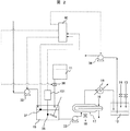
図1は、二酸化炭素分離・回収システムの概略構成を示したものである。 FIG. 1 shows a schematic configuration of a carbon dioxide separation / recovery system.
本図において、二酸化炭素分離・回収システム(二酸化炭素回収システムとも呼ぶ。)は、CO2回収装置20と吸収液再生装置30(劣化吸収液再生装置とも呼ぶ。)とを含む構成である。CO2回収装置20は、吸収液102を用いてCO2を吸収する吸収塔5、CO2を吸収した吸収液104からCO2を脱離する再生塔8、脱離したCO2を液化する圧縮機4等を含む。また、吸収液再生装置30は、劣化した吸収液102を抜出して貯留する混合用タンク15(アルカリ剤混合部)、アルカリ剤調製タンク11、蒸発缶17(分離部)、凝縮液タンク12等を含む。
In this figure, a carbon dioxide separation / recovery system (also referred to as a carbon dioxide recovery system) includes a CO 2 recovery device 20 and an absorbent regenerator 30 (also referred to as a deteriorated absorbent regenerator). CO 2 recovery unit 20, compression to liquefy the
微粉炭焚きボイラで発生した燃焼排ガス1は、窒素酸化物(NOx)を除去する脱硝装置、及び煤塵を除去する集塵装置を経て、硫黄酸化物(SOx)を除去する脱硫装置3に入る。脱硫装置3を経た燃焼排ガス101は、CO2回収装置20に導入される。
The
CO2回収装置20において、脱硫装置3を経た燃焼排ガス101は、吸収塔5に導かれる。この燃焼排ガス101は、CO2の吸収液102と気液接触し、燃焼排ガス101に含まれるCO2が吸収される。吸収液102は、例えば、アミン水溶液が好適である。
In the CO 2 recovery device 20, the
吸収塔5でCO2が除去された排ガス103は、煙突7から排出される。一方、CO2を吸収した吸収液102は、液液熱交換器6でCO2を放出する温度にまで加熱され、再生塔8に導かれ、CO2を脱離する。再生塔8でCO2を脱離した吸収液104は、液液熱交換器6で冷却され、吸収塔5に導かれる。
The
このように、吸収液102、104が吸収塔5と再生塔8とを循環するように構成することにより、CO2の吸収・脱離を繰り返すことができる。
In this way, by configuring the
吸収液102、104は、CO2を吸収させる場合は低温に、CO2を脱離させる場合は高温にする必要がある。液液熱交換器6は、この温度差に対する熱エネルギーを有効利用している。さらに、CO2の吸収温度及び脱離温度は、吸収液102、104の種類によって最適な温度があり、図示していないが、加熱器や冷却器を追設して、効率よくCO2の吸収・脱離を行う。
The absorbing
再生塔8で脱離したCO2を含むガス105には水蒸気も含まれるため、冷却器9でガス105の除湿を行った後、ガス106を圧縮機4で圧縮して、ガス106に含まれるCO2を液化する。
Since the
SOxを含むガスが吸収液102に接触すると、吸収液102にSOxが吸収され、吸収液102に含まれるアミンとSOxとが反応し、安定な塩を生成する。この塩は、HSS(Heat Stable Salt)と称されている。燃焼排ガス1に含まれるSOxは、脱硫装置3でSOxの大部分を除去するため、吸収液102、104に混入するSOxは、比較的少量ではあるが、吸収液102、104が二酸化炭素回収のために繰り返し使用されているうちに徐々にHSSとして蓄積される。
When a gas containing SOx comes into contact with the absorbing
CO2は、吸収液102に吸収される際、アミンと反応する。CO2は、吸収液102を加熱することによって脱離するが、SOxは、CO2の脱離温度では脱離しない。吸収液102、104は、循環させて使用するため、吸収液102の中で生成したHSSは、吸収液102、104に蓄積される。HSSの量が多くなるとCO2の吸収性能は低下する。
When CO 2 is absorbed by the absorbing
以下、CO2の吸収性能が低下した吸収液102、104を劣化吸収液と呼ぶことにする。本実施例においては、劣化吸収液が劣化アミン水溶液であるものとして記載しているが、劣化吸収液は、これに限定されるものではない。
Hereinafter, the absorbing
劣化吸収液を再生するには、まず、劣化吸収液にアルカリ剤を添加してHSSからSOx分を切り離す。アルカリ剤としては、例えば、炭酸ナトリウム(Na2CO3)が挙げられる。 In order to regenerate the degraded absorbent, first, an alkaline agent is added to the degraded absorbent and the SOx content is separated from the HSS. Examples of the alkaline agent include sodium carbonate (Na 2 CO 3 ).
劣化吸収液にアルカリ剤を添加すると、劣化吸収液に含まれるアミンは再生されるが、Naイオン(Na+)及びSO4イオン(SO4 2-)が不純物として劣化吸収液に残存しているため、これらの不純物を取り除く必要がある。取り除く方法としては、蒸留法、電気透析法及びイオン交換樹脂法がある。 When an alkaline agent is added to the deterioration absorbing solution, the amine contained in the deterioration absorbing solution is regenerated, but Na ions (Na + ) and SO 4 ions (SO 4 2− ) remain as impurities in the deterioration absorbing solution. Therefore, it is necessary to remove these impurities. Examples of the removing method include a distillation method, an electrodialysis method, and an ion exchange resin method.
蒸留法は、水及びアミンを蒸発させ、NaイオンとSO4イオンとを反応させ、Na2SO4等を析出させて除去する方法である。 The distillation method is a method in which water and amine are evaporated, Na ions and SO 4 ions are reacted, and Na 2 SO 4 and the like are precipitated and removed.
電気透析法は、溶液に電圧を印加し、イオン交換膜を介してNaイオン及びSO4イオンを選択的に透過させることにより、Naイオン及びSO4イオンをイオン交換膜で仕切られた領域に集めて除去する方法である。 The electrodialysis method collects Na ions and SO 4 ions in a region partitioned by an ion exchange membrane by applying a voltage to the solution and selectively allowing Na ions and SO 4 ions to pass through the ion exchange membrane. It is a method to remove.
イオン交換膜法は、イオン交換膜にNaイオン及びSO4イオンを吸着させて除去する方法である。 The ion exchange membrane method is a method in which Na ions and SO 4 ions are adsorbed and removed from the ion exchange membrane.
本実施例においては、蒸留法を用いて説明するが、電気透析法やイオン交換膜法を適用してもよい。 In the present embodiment, description will be made using a distillation method, but an electrodialysis method or an ion exchange membrane method may be applied.
吸収液再生装置30においては、CO2回収装置20の吸収塔5から吸収液102(劣化吸収液)を送液ポンプ32(第一の送液部)によって抜出し、混合用タンク15に貯留する。この混合用タンク15にアルカリ剤調製タンク11よりアルカリ水溶液を添加し、HSSからSOxを切り離してアミンを生成する。アルカリ水溶液の添加量は、バルブ36の開度を調節することによって制御する。アルカリ水溶液の種類によっては、HSSからSOxを切り離す反応が遅いため、混合用タンク15を設けることにより攪拌等による反応の均一化を図ることができ、滞留時間を稼ぐことができる。これにより、添加するアルカリ剤の使用量を抑制することができる。
In the
混合用タンク15でHSSからSOx分を切り離した液は、送液ポンプ33によって蒸発缶17に導き、蒸気16の熱を利用して加熱する。水及びアミンが蒸発することにより析出した残渣(濃縮液)は、抜出し管18から排出する。一方、蒸発した水及びアミンは、ガス冷却器19で凝縮し、凝縮液タンク12に貯留される。
The liquid obtained by separating the SOx component from the HSS in the
凝縮液タンク12においては、アミン13及び水14を供給してアミン濃度を調整する。すなわち、凝縮液タンク12は濃度調整部である。凝縮液タンク12内の液は、送液ポンプ34(第二の送液部)を介してCO2回収装置20の再生塔8に戻すことにより再利用する。
In the
HSSにアルカリ水溶液を添加し、HSS中のSOxを切り離す工程において、アルカリ剤の添加量を過剰にすれば、析出物の量が多くなる。例えば、Na2CO3を使用すれば、析出物としてNa2SO4の他、Na2CO3も析出する。したがって、アルカリ剤の添加量は、必要量を添加すればよく、多すぎれば過剰となり、アルカリ剤の浪費となる。この問題を解決するためには、アルカリ剤の添加量を制御することが重要となる。 In the step of adding an alkaline aqueous solution to HSS and separating SOx in HSS, if the amount of alkali agent added is excessive, the amount of precipitates increases. For example, the use of Na 2 CO 3, other Na 2 SO 4 as a precipitate, Na 2 CO 3 is also precipitated. Therefore, the alkali agent may be added in a necessary amount, and if it is too much, it becomes excessive and wastes the alkali agent. In order to solve this problem, it is important to control the amount of alkali agent added.
図2は、アルカリ剤の添加量を調節する制御部を付設した劣化吸収液再生部(図1の吸収液再生装置30)を示したものである。
FIG. 2 shows a deteriorated absorbent regenerating part (absorbing
本図に示すように、劣化吸収液再生部は、混合用タンク15、蒸発缶17、凝縮液タンク12等で構成されている。送液ポンプ32は、図1の吸収塔5から混合用タンク15に劣化吸収液(図1の吸収液102)を送るものである。送液ポンプ33は、アルカリ剤調製タンク11のアルカリ剤を混合した劣化吸収液を混合用タンク15から蒸発缶17に送るものである。蒸発缶17で加熱されて蒸発した水及びアミンは、ガス冷却器19で凝縮し、凝縮液タンク12に貯留される。
As shown in this figure, the deteriorated absorbent regenerating part is composed of a
本図において、混合用タンク15の内部には、液採取部35及び液位センサ37を設けてある。液採取部35は、混合用タンク15内の液(劣化吸収液)を採取してHSS濃度測定部151に送るものであり、HSS濃度測定部151は、液に含まれるHSSの濃度を測定し、その濃度を電気信号に変換して制御部40に送るようになっている。本実施例は、HSS濃度測定部151が液体クロマトグラフの場合である。HSS濃度測定部151は、硫酸イオン、亜硫酸イオン等のSOx成分を総量として測定するものであってもよい。ここで、液採取部35及びHSS濃度測定部151をまとめて硫黄酸化物濃度検出部と呼ぶ。
In the drawing, a
制御部40は、この濃度に関する電気信号、液位センサ37で測定した混合用タンク15の液位等から、必要になるアルカリ剤添加量を算出し、バルブ36に開閉指令を送り、必要量を添加する。これらの一連の操作は、自動化することが可能である。これにより、必要量のアルカリ剤を添加することができる。
The
以下、制御部40に関連する事項について更に説明する。
Hereinafter, matters related to the
液位センサ37は、送液ポンプ32を稼動することにより混合用タンク15に導いた劣化吸収液が所定の液位に達した場合にも制御部40に信号を送る。この場合、制御部40は、送液ポンプ32を停止する。これも自動化することができる。
The
送液ポンプ32を稼働すると、図1のCO2回収装置20で使用される吸収液102、104(アミン水溶液)が減少するため、減少した吸収液102、104を凝縮液タンク12から補充する必要がある。抜出した劣化吸収液の量、及び補充する再生吸収液の量はそれぞれ、送液ポンプ32、34の出力から算出することができるため、送液ポンプ32、34の出力信号を制御部40に送って計算を行い、送液ポンプ32、34の回転数等の制御を自動的に行うことができる。
When the
凝縮液タンク12は、蒸発缶17で蒸発してガス冷却器19で凝縮した水及びアミンを貯留するものであるが、凝縮液のアミン及び水の組成は、CO2回収装置で必要になる組成と同じとは限らない。このため、凝縮液タンク12にアミン13及び水14を供給できるようにし、凝縮液の組成を調整できるようにしてある。
The
混合用タンク15内の劣化吸収液にアルカリ剤を必要量添加し、HSSからSOx成分を脱離した後、送液ポンプ33を稼動して蒸発缶17に混合用タンク15内の液を導く。混合用タンク15内の液が所定の液位以下になった時点で、送液ポンプ33を停止し、再度、送液ポンプ32を稼働して劣化吸収液を混合用タンク15に導き、同様の操作で劣化吸収液を再生する。
A necessary amount of an alkaline agent is added to the deterioration absorbing liquid in the
送液ポンプ32、33、34の液の吐出流量は、同一であることが望ましい。これにより、混合用タンク15、蒸発缶17及び凝縮液タンク12内の吸収液の量が一定に保持され、安定した操作を実現することができる。
It is desirable that the liquid discharge flow rates of the liquid feed pumps 32, 33, and 34 are the same. Thereby, the amount of the absorbing liquid in the
上記のように安定した操作を実現することにより、図1のCO2回収装置20と同時に稼動することが可能になる。混合用タンク15、蒸発缶17及び凝縮液タンク12の容量は、劣化吸収液の必要とされる再生速度に合わせて設計すればよく、CO2回収装置20の停止期間だけの稼動に限定されない。このため、混合用タンク15、蒸発缶17及び凝縮液タンク12の容量は、停止期間だけ稼動する場合に比べて小型化することができる。
By realizing stable operation as described above, it becomes possible to operate simultaneously with the CO 2 recovery device 20 of FIG. The capacities of the mixing
実施例1の場合、図1のCO2回収装置20は連続操作である。これに対して、吸収液再生装置30は回分操作が基本となる。これは、図1の吸収液102、104に蓄積されるSOx成分の量がCO2の処理量に比べて格段に少ないためである。そこで、本実施例においては、吸収液再生装置30も連続操作とする構成を示す。
In the case of Example 1, the CO 2 recovery device 20 in FIG. 1 is a continuous operation. On the other hand, the
図3は、図1のCO2回収装置20及び吸収液再生装置30を連続稼動させる構成を示したものである。
FIG. 3 shows a configuration in which the CO 2 recovery device 20 and the
図1のCO2回収装置20及び吸収液再生装置30を同時に連続稼動させるには、CO2回収装置20内のHSS濃度を連続計測する必要がある。
In order to continuously operate the CO 2 recovery device 20 and the
そこで、本図においては、液採取部35を再生塔8の下部に設置し、貯留される吸収液104をサンプリングしてHSS濃度をHSS濃度測定部151で測定するようにしてある。なお、液採取部35は、吸収塔5の下部に設置し、貯留される吸収液102をサンプリングしてもよい。本実施例のHSS濃度測定部151も液体クロマトグラフである。
Therefore, in this figure, the
また、吸収塔5に送られる燃焼排ガス1(吸収塔5の入口部のガス)の一部を採取するガス採取部301、及び吸収塔5から煙突7に送られるガス(吸収塔5の出口部のガス)の一部を採取するガス採取部303を利用してガスクロマトグラフ等のガス分析部302でSOxの濃度を計測し、それらの濃度差から吸収液102のHSS濃度(硫黄酸化物の濃度)を算出してもよい。
In addition, a
本図においては、再生塔8の吸収液104を送液ポンプ32によってスタティック型ミキサー38(アルカリ剤混合部)に導き、アルカリ剤調製タンク11から送液ポンプ33によって送られるアルカリ剤と混合するようになっている。スタティック型ミキサー38を出た液は、蒸発缶17に導かれる。なお、本図における蒸発缶17及び凝縮液タンク12の構成は、実施例1と同様である。
In this figure, the
ここで、再生塔8から送液ポンプ32によって抜き出される吸収液104の流量を劣化吸収液抜出し流量FHSSと呼ぶことにする。また、アルカリ剤調製タンク11から送液ポンプ33によって送られるアルカリ剤の流量は、アルカリ水溶液流量FOHと呼ぶことにする。
Here, the flow rate of the absorbing liquid 104 extracted from the regeneration tower 8 by the
HSS濃度測定部35で得られた濃度信号を制御部40に取り込み、必要となるアルカリ剤の添加量を算出し、制御部40で劣化吸収液(吸収液104)の送液ポンプ32及びアルカリ水溶液の送液ポンプ33の動力を制御するようにしてある。送液ポンプ32、33の動力制御により、劣化吸収液及びアルカリ水溶液の連続供給流量を制御する。
The concentration signal obtained by the HSS
劣化吸収液を抜出すことにより、CO2回収装置20内の吸収液が減るため、減少した分を凝縮液タンク12から送液ポンプ34を介して補充する。抜出した劣化吸収液の量、及び補充する吸収液の量の制御は制御部40で自動化している。
By extracting the deteriorated absorption liquid, the absorption liquid in the CO 2 recovery device 20 is reduced, and the reduced amount is replenished from the
ここで、凝縮液タンク12から送液ポンプ34によって送られる再生吸収液補充流量FAと呼ぶことにする。
Here, the regenerated absorbent replenishing flow rate F A sent from the
劣化吸収液とアルカリ水溶液とをスタティック型ミキサー38に導入し、混合するようにした。実施例2においては混合用タンクであったが、HSSからSOx分を切り離す反応が速いアルカリ剤を用いる場合には、スタティック型ミキサーを用いることができ、混合部の容積を低減することができる。 The deterioration absorbing liquid and the alkaline aqueous solution were introduced into the static mixer 38 and mixed. In Example 2, the mixing tank was used. However, in the case of using an alkaline agent that rapidly removes SOx from HSS, a static mixer can be used, and the volume of the mixing unit can be reduced.
つぎに、図1のCO2回収装置20及び吸収液再生装置30の連続稼動の手順について説明する。
Next, the procedure for continuous operation of the CO 2 recovery device 20 and the
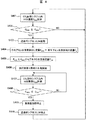
図4は、CO2回収装置及び吸収液再生装置の連続稼動の工程を示すフロー図である。本図の説明は、主として図3の構成に基づくものである。 FIG. 4 is a flowchart showing the steps of continuous operation of the CO 2 recovery device and the absorbent regenerator. The description of this figure is mainly based on the configuration of FIG.
図4においては、図1のCO2回収装置20を構成する再生塔8内の吸収液104のHSS濃度CHSSを一定の時間間隔で計測する(S401)。その濃度CHSSが規定のCHSS *1以上になった時点で図1の吸収液再生装置30を稼動する(S402)。
In FIG. 4, the HSS concentration C HSS of the absorbent 104 in the regeneration tower 8 constituting the CO 2 recovery apparatus 20 of FIG. 1 is measured at regular time intervals (S401). When the concentration C HSS becomes equal to or higher than the prescribed C HSS * 1 , the
3基の送液ポンプ32、33、34を起動し(S403)、劣化吸収液抜出し流量FHSS及び再生吸収液補充流量FAが同じになるようにする(S404)。さらに、FHSS 及びCHSSからアルカリ水溶液流量FOHを算出し、供給する(S405)。 The three liquid feed pumps 32, 33, and 34 are activated (S403) so that the deteriorated absorbent extraction flow rate F HSS and the regenerated absorbent replenishment flow rate F A are the same (S404). Further, the alkaline aqueous solution flow rate F OH is calculated from F HSS and C HSS and supplied (S405).
蒸発缶17は、空焚きしないように規定の液位になった後に加熱する(S406)。さらに、図示していないが、液位が高くなり過ぎないように、FHSS、及びFHSSに合わせて供給するFOHを制御する機能を有することが望ましい。
The
吸収液再生装置を稼動している間、CO2回収装置内には再生吸収液が補充されるため、吸収液中のHSS濃度は低下する。吸収液を再生するには、蒸発させるためのエネルギーが必要であり、HSS濃度が低い場合の再生処理は無駄なエネルギーを使用することになる。 While the absorbent regenerator is in operation, the regenerated absorbent is replenished in the CO 2 recovery device, so the HSS concentration in the absorbent decreases. In order to regenerate the absorbing solution, energy for evaporating is required, and the regeneration processing when the HSS concentration is low uses useless energy.
そこで、吸収液再生装置を稼動している間、一定の時間間隔でHSS濃度CHSSを計測し(S407)、その濃度CHSSが規定のCHSS *2以下になった時点(S408)で吸収液再生装置の蒸発缶17の加熱を停止する操作(S409)及び送液ポンプ32、33、34の停止操作を行うことが望ましい。
Therefore, the HSS concentration C HSS is measured at regular intervals while the absorbent regenerator is in operation (S407), and the absorption is performed when the concentration C HSS falls below the specified C HSS * 2 (S408). It is desirable to perform an operation (S409) for stopping the heating of the
以下、HSS濃度の計測方法について説明する。 Hereinafter, a method for measuring the HSS concentration will be described.
吸収液に含まれるアミン(R-NH2)と硫黄酸化物(SOx)とからHSSすなわち(R-NH2)2SOxが生成する反応は、上記反応式(1)で表される。 The reaction in which HSS, that is, (R—NH 2 ) 2 SOx, is generated from amine (R—NH 2 ) and sulfur oxide (SOx) contained in the absorbing solution is represented by the above reaction formula (1).
HSSにはSが含まれていることから、HSSのS分を計測すればよい。 Since S is included in HSS, it is only necessary to measure S part of HSS.
また、HSSにアルカリ剤、例えばNa2CO3を加える反応は、上記反応式(2)で表される。 The reaction of adding an alkaline agent such as Na 2 CO 3 to HSS is represented by the above reaction formula (2).
上記反応式(2)においてSO4 2- は硫酸イオンであり、この硫酸イオンを計測すればよい。 In the reaction formula (2), SO 4 2- is a sulfate ion, and this sulfate ion may be measured.
硫酸イオンは、イオンクロマト法、あるいは、陰イオンを交換する吸着材に通した後、酸で洗浄、滴定する方法で計測することができる。 The sulfate ion can be measured by ion chromatography or a method of passing through an adsorbent for exchanging anions and then washing and titrating with an acid.
いずれの方法を用いてもよいが、本実施例においては、硫酸イオンを計測する方法を採用した。 Any method may be used, but in this example, a method of measuring sulfate ions was adopted.
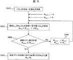
図5は、硫酸イオン濃度の分析手順を示すフロー図である。 FIG. 5 is a flowchart showing the analysis procedure of the sulfate ion concentration.
図3の再生塔8から一定量の吸収液104(アミン水溶液Wa)を採取し(S501)、Na2CO3を一定量ΔWOH加える(S502)。その際に生成する硫酸イオン量WSO4,tを計測する(S503)。WSO4,tがこの計測の前の計測における硫酸イオン量WSO4,t-1より多ければ、再びNa2CO3を一定量ΔWOH加え(S502)、WSO4,tを計測する(S503)。WSO4,tがWSO4,t-1以下であれば、アルカリ剤であるNa2CO3の供給量(添加量)は、吸収液104に必要とされる供給量に達したと判定する(S505)。ここで、繰り返し添加したNa2CO3の積算量をWOHと定義する。 A fixed amount of absorbing liquid 104 (amine aqueous solution W a ) is collected from the regeneration tower 8 of FIG. 3 (S501), and a certain amount of ΔW OH is added to Na 2 CO 3 (S502). The amount of sulfate ion W SO4, t generated at that time is measured (S503). If W SO4, t is larger than the sulfate ion amount W SO4, t-1 in the measurement before this measurement, Na 2 CO 3 is added again by a certain amount ΔW OH (S502), and W SO4, t is measured (S503). . If W SO4, t is equal to or lower than W SO4, t−1, it is determined that the supply amount (addition amount) of the alkaline agent Na 2 CO 3 has reached the supply amount required for the absorbent 104 ( S505). Here, the cumulative amount of Na 2 CO 3 added repeatedly is defined as W OH .
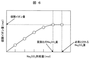
図6は、硫酸イオン濃度の計測結果を示すグラフである。横軸にNa2CO3供給量をとり、縦軸に硫酸イオン量をとっている。 FIG. 6 is a graph showing the measurement result of the sulfate ion concentration. The horizontal axis represents the amount of Na 2 CO 3 supplied, and the vertical axis represents the amount of sulfate ions.
本図において、採取した吸収液104に対するNa2CO3供給量が増加するに従って、硫酸イオン量は増加する。ただし、量論比とされるNa2CO3供給量に達した後は、Na2CO3を追加供給しても硫酸イオン量はほとんど増加しない。 In this figure, as the amount of Na 2 CO 3 supplied to the collected absorbent 104 increases, the amount of sulfate ions increases. However, after reaching the stoichiometric ratio of Na 2 CO 3 supply, even if additional Na 2 CO 3 is supplied, the amount of sulfate ions hardly increases.
上記反応式(2)からも分かるように、Na2CO3の添加量の増加に従って、HSSからSOx分が切り離される。典型的には、硫酸イオン量が増加する。 As can be seen from the reaction formula (2), the SOx content is separated from the HSS as the amount of Na 2 CO 3 added increases. Typically, the amount of sulfate ions increases.
本図においては、アミン水溶液Waにおける硫酸イオン量、及び必要とされるNa2CO3量を示してある。プロットしたNa2CO3量の間隔は、図5のΔWOHと等しくしてある。この間隔を小さくし、アミン水溶液Waにおける硫酸イオン量の精度を上げることが望ましい。 In this figure, there is shown a Na 2 CO 3 amount of sulfate ion amount, and required in the aqueous amine solution W a. The interval between the plotted Na 2 CO 3 amounts is equal to ΔW OH in FIG. This interval is reduced, it is desirable to increase the accuracy of the amount of sulfate ions in the aqueous amine solution W a.
得られたアミン水溶液Waにおける硫酸イオン量、及びNa2CO3の合計量WOHから、単位アミン水溶液における必要なNa2CO3量をWa/WOHで求めることができる。 Sulfate ion amount in the resulting aqueous amine solution W a, and Na from the total amount W OH of 2 CO 3, the Na 2 CO 3 amount required per unit amine solution can be obtained by W a / W OH.
なお、実際の工程においては、量論比とされるNa2CO3供給量よりも多量のNa2CO3を追加供給することが望ましい。この理由は、吸収液104にNa2CO3を添加した際の反応が必ずしも短時間で均一に進行するとは限らず、未反応の硫黄酸化物が残存することにより吸収液104の劣化が進むことを可能な限り抑制するためである。
In the actual process, it is desirable to add supplying a large amount of Na 2 CO 3 than Na 2 CO 3 supply amount that is stoichiometric. This is because the reaction when Na 2 CO 3 is added to the absorbing
以上の実施例においては、SOx濃度を液体クロマトグラフで計測しているが、これに限定されるものではなく、吸収塔の入口及び出口のガスをサンプリングしてガスクロマトグラフ等のガス分析によって計測してもよく、これを送液ポンプ等の制御に用いてもよい。 In the above embodiment, the SOx concentration is measured by a liquid chromatograph, but the present invention is not limited to this, and the gas at the inlet and outlet of the absorption tower is sampled and measured by gas analysis such as a gas chromatograph. It may be used for controlling a liquid feed pump or the like.
また、以上の実施例においては、吸収液としてアミン水溶液を用いたが、本発明は、これに限定されるものではなく、弱アルカリ性物質とその溶媒とを含み弱アルカリ性を呈するCO2吸収液であれば適用可能である。この弱アルカリ性物質は、Na2CO3等のアルカリ剤よりもpHが低いものが好適である。また、この弱アルカリ性物質は、アルカリ剤よりも沸点が低いことが望ましい。 Further, in the above examples, an aqueous amine solution was used as the absorbing solution, but the present invention is not limited to this, and a CO 2 absorbing solution that exhibits weak alkalinity including a weakly alkaline substance and its solvent. Applicable if available. The weak alkaline substance preferably has a lower pH than an alkaline agent such as Na 2 CO 3 . Moreover, it is desirable that this weakly alkaline substance has a lower boiling point than the alkaline agent.
硫黄酸化物が水などの溶媒に溶解した場合に生じる硫黄を含む陰イオンと、アルカリ剤が水などの溶媒に溶解した場合に生じる陽イオンとが、溶媒を蒸発させた際に結合して生じる塩を硫黄酸化物の塩と呼ぶことにする。 An anion containing sulfur generated when a sulfur oxide is dissolved in a solvent such as water and a cation generated when an alkaline agent is dissolved in a solvent such as water are combined to form when the solvent is evaporated. The salt will be referred to as a sulfur oxide salt.
1:燃焼排ガス、3:脱硫装置、4:圧縮機、5:吸収塔、6:液液熱交換器、7:煙突、8:再生塔、9:冷却器、11:アルカリ剤調製タンク、12:凝縮液タンク、13:アミン、14:水、15:混合用タンク、16:蒸気、17:蒸発缶、18:抜出し管、19:ガス冷却器、20:CO2回収装置、30:吸収液再生装置、32、33、34:送液ポンプ、35:液採取部、36:バルブ、37:液位センサ、38:スタティック型ミキサー、40:制御部、102、104:吸収液、151:HSS濃度測定部、301、303:ガス採取部、302:ガス分析部。 1: combustion exhaust gas, 3: desulfurizer, 4: compressor, 5: absorption tower, 6: liquid-liquid heat exchanger, 7: chimney, 8: regeneration tower, 9: cooler, 11: alkaline agent preparation tank, 12 : condensate tank 13: amine, 14: water, 15: mixing tank, 16: steam, 17: evaporator, 18: extraction tube, 19: gas cooler, 20: CO 2 recovery apparatus, 30: absorbing liquid Regenerating apparatus, 32, 33, 34: liquid feed pump, 35: liquid sampling part, 36: valve, 37: liquid level sensor, 38: static mixer, 40: control part, 102, 104: absorbing liquid, 151: HSS Concentration measuring unit, 301, 303: gas sampling unit, 302: gas analyzing unit.
Claims (15)
Priority Applications (1)
| Application Number | Priority Date | Filing Date | Title |
|---|---|---|---|
| JP2011107876A JP2012236170A (en) | 2011-05-13 | 2011-05-13 | Method and apparatus for regeneration of deteriorated absorbing liquid, and carbon dioxide recovery system using the same |
Applications Claiming Priority (1)
| Application Number | Priority Date | Filing Date | Title |
|---|---|---|---|
| JP2011107876A JP2012236170A (en) | 2011-05-13 | 2011-05-13 | Method and apparatus for regeneration of deteriorated absorbing liquid, and carbon dioxide recovery system using the same |
Publications (2)
| Publication Number | Publication Date |
|---|---|
| JP2012236170A true JP2012236170A (en) | 2012-12-06 |
| JP2012236170A5 JP2012236170A5 (en) | 2013-11-07 |
Family
ID=47459576
Family Applications (1)
| Application Number | Title | Priority Date | Filing Date |
|---|---|---|---|
| JP2011107876A Pending JP2012236170A (en) | 2011-05-13 | 2011-05-13 | Method and apparatus for regeneration of deteriorated absorbing liquid, and carbon dioxide recovery system using the same |
Country Status (1)
| Country | Link |
|---|---|
| JP (1) | JP2012236170A (en) |
Cited By (7)
| Publication number | Priority date | Publication date | Assignee | Title |
|---|---|---|---|---|
| CN104226086A (en) * | 2013-06-14 | 2014-12-24 | 株式会社东芝 | Acidic gas collection system and acidic gas collection apparatus |
| JPWO2014136599A1 (en) * | 2013-03-04 | 2017-02-09 | 三菱重工業株式会社 | CO2 recovery system and CO2 recovery method |
| JP2017113665A (en) * | 2015-12-21 | 2017-06-29 | 株式会社東芝 | Carbon dioxide separation and recovery system and operation control method for the same |
| WO2017122443A1 (en) | 2016-01-14 | 2017-07-20 | 三菱重工業株式会社 | Acidic gas recovery system and reclaiming device to be used in same |
| WO2019078156A1 (en) | 2017-10-20 | 2019-04-25 | 三菱重工エンジニアリング株式会社 | Acidic gas removal apparatus and acidic gas removal method |
| WO2019078168A1 (en) | 2017-10-20 | 2019-04-25 | 三菱重工エンジニアリング株式会社 | Reclaiming device and reclaiming method |
| WO2019087762A1 (en) * | 2017-10-31 | 2019-05-09 | 三菱重工エンジニアリング株式会社 | Method and system for recovering acidic gas |
Citations (4)
| Publication number | Priority date | Publication date | Assignee | Title |
|---|---|---|---|---|
| JPH03213125A (en) * | 1990-01-17 | 1991-09-18 | Babcock Hitachi Kk | Absorbent ph control apparatus of wet exhaust gas desulfurizer |
| JPH0889756A (en) * | 1994-09-28 | 1996-04-09 | Tokyo Electric Power Co Inc:The | Treatment of carbon dioxide in gas to be treated and liquid absorbent |
| JP2008200621A (en) * | 2007-02-21 | 2008-09-04 | Mitsubishi Heavy Ind Ltd | Exhaust gas desulfurizer |
| WO2010142716A1 (en) * | 2009-06-09 | 2010-12-16 | Aker Clean Carbon As | Method for reclaiming of co2 absorbent and a reclaimer |
-
2011
- 2011-05-13 JP JP2011107876A patent/JP2012236170A/en active Pending
Patent Citations (5)
| Publication number | Priority date | Publication date | Assignee | Title |
|---|---|---|---|---|
| JPH03213125A (en) * | 1990-01-17 | 1991-09-18 | Babcock Hitachi Kk | Absorbent ph control apparatus of wet exhaust gas desulfurizer |
| JPH0889756A (en) * | 1994-09-28 | 1996-04-09 | Tokyo Electric Power Co Inc:The | Treatment of carbon dioxide in gas to be treated and liquid absorbent |
| JP2008200621A (en) * | 2007-02-21 | 2008-09-04 | Mitsubishi Heavy Ind Ltd | Exhaust gas desulfurizer |
| WO2010142716A1 (en) * | 2009-06-09 | 2010-12-16 | Aker Clean Carbon As | Method for reclaiming of co2 absorbent and a reclaimer |
| JP2012529364A (en) * | 2009-06-09 | 2012-11-22 | エイカー クリーン カーボン エーエス | Method and recycling device for recycling CO2 absorbent |
Cited By (18)
| Publication number | Priority date | Publication date | Assignee | Title |
|---|---|---|---|---|
| JPWO2014136599A1 (en) * | 2013-03-04 | 2017-02-09 | 三菱重工業株式会社 | CO2 recovery system and CO2 recovery method |
| US9623366B2 (en) | 2013-03-04 | 2017-04-18 | Mitsubishi Heavy Industries, Ltd. | CO2 recovery system and CO2 recovery method |
| CN104226086A (en) * | 2013-06-14 | 2014-12-24 | 株式会社东芝 | Acidic gas collection system and acidic gas collection apparatus |
| US10786781B2 (en) | 2015-12-21 | 2020-09-29 | Kabushiki Kaisha Toshiba | Carbon dioxide separation and capture apparatus and method of controlling operation of carbon dioxide separation and capture apparatus |
| JP2017113665A (en) * | 2015-12-21 | 2017-06-29 | 株式会社東芝 | Carbon dioxide separation and recovery system and operation control method for the same |
| CN106943844A (en) * | 2015-12-21 | 2017-07-14 | 株式会社东芝 | The method of the operation of carbon dioxide separation and acquisition equipment and control carbon dioxide separation and acquisition equipment |
| CN106943844B (en) * | 2015-12-21 | 2021-03-12 | 株式会社东芝 | Carbon dioxide separation and capture device and method of controlling operation of carbon dioxide separation and capture device |
| WO2017122443A1 (en) | 2016-01-14 | 2017-07-20 | 三菱重工業株式会社 | Acidic gas recovery system and reclaiming device to be used in same |
| JP2017124374A (en) * | 2016-01-14 | 2017-07-20 | 三菱重工業株式会社 | Acidic gas recovery system and reclaiming device used for the same |
| US10940430B2 (en) | 2016-01-14 | 2021-03-09 | Mitsubishi Heavy Industries Engineering, Ltd. | Acidic gas recovery system and reclaiming device to be used in same |
| WO2019078168A1 (en) | 2017-10-20 | 2019-04-25 | 三菱重工エンジニアリング株式会社 | Reclaiming device and reclaiming method |
| US10874976B2 (en) | 2017-10-20 | 2020-12-29 | Mitsubishi Heavy Industries Engineering, Ltd. | Acid gas removal apparatus and acid gas removal method |
| WO2019078156A1 (en) | 2017-10-20 | 2019-04-25 | 三菱重工エンジニアリング株式会社 | Acidic gas removal apparatus and acidic gas removal method |
| US11148095B2 (en) | 2017-10-20 | 2021-10-19 | Mitsubishi Heavy Industries Engineering, Ltd. | Reclaiming apparatus and method for reclaiming |
| JP2019081151A (en) * | 2017-10-31 | 2019-05-30 | 三菱重工エンジニアリング株式会社 | Acidic gas recovery method and system |
| WO2019087762A1 (en) * | 2017-10-31 | 2019-05-09 | 三菱重工エンジニアリング株式会社 | Method and system for recovering acidic gas |
| US11311833B2 (en) | 2017-10-31 | 2022-04-26 | Mitsubishi Heavy Industries Engineering, Ltd. | Method and system for recovering acidic gas |
| JP7134618B2 (en) | 2017-10-31 | 2022-09-12 | 三菱重工エンジニアリング株式会社 | Acid gas recovery method and system |
Similar Documents
| Publication | Publication Date | Title |
|---|---|---|
| JP2012236170A (en) | Method and apparatus for regeneration of deteriorated absorbing liquid, and carbon dioxide recovery system using the same | |
| JP5703106B2 (en) | Amine recovery system and carbon dioxide recovery system | |
| CA2826750C (en) | Method of controlling co2 chemical absorption system | |
| CN102959386B (en) | Mercury removing method in the removing of gas analyzing apparatus, mercury system, analysis method for gases and waste gas | |
| JP5479949B2 (en) | Measuring device, measuring method, and carbon dioxide recovery system | |
| BRPI1012594B1 (en) | method to eliminate or substantially reduce the emission of amines and alkaline decomposition products from them to the atmosphere | |
| KR101476310B1 (en) | Removal of non-volatiles from ammonia - based c0₂-absorbent solution | |
| US20120230875A1 (en) | Carbon dioxide separation and recovery apparatus | |
| EP2230000B1 (en) | Flue gas treatment system and method using ammonia solution | |
| US9579602B2 (en) | Catalytic CO2 desorption for ethanolamine based CO2 capture technologies | |
| JP5762253B2 (en) | Control method for CO2 chemical absorption system | |
| WO2012067101A1 (en) | Method and device for controlling system for chemically absorbing carbon dioxide | |
| JP2017124374A (en) | Acidic gas recovery system and reclaiming device used for the same | |
| JP2014185913A (en) | Method for analyzing amount of heat stable salt contained in absorbing solution and method for recovering carbon dioxide from gas to be treated | |
| KR20110000684A (en) | Improved alkanolamines for co2 removal from gas streams | |
| JP2003093835A (en) | Regeneration method for gas absorbing liquid and regeneration system for gas absorbing liquid | |
| EP3403713B1 (en) | Co2 recovery device and recovery method | |
| AU2015212069A1 (en) | Gas absorption and regeneration apparatus and method for operating same | |
| JP5703240B2 (en) | Amine recovery device, amine recovery method, and carbon dioxide recovery system | |
| JP2013208531A (en) | Carbon dioxide recovery system | |
| CA2834664C (en) | Method and apparatus for capturing sox in a flue gas processing system | |
| JP2013208533A (en) | Carbon dioxide recovery system | |
| KR20220104675A (en) | Regeneration method of carbonic acid-type layered double hydroxide and acid exhaust gas treatment facility | |
| WO2022044487A1 (en) | Carbon dioxide recovery system | |
| JP7431708B2 (en) | Acid gas removal control device, acid gas removal control method, and acid gas removal device |
Legal Events
| Date | Code | Title | Description |
|---|---|---|---|
| A521 | Written amendment |
Free format text: JAPANESE INTERMEDIATE CODE: A523 Effective date: 20130918 |
|
| A621 | Written request for application examination |
Free format text: JAPANESE INTERMEDIATE CODE: A621 Effective date: 20130918 |
|
| A977 | Report on retrieval |
Free format text: JAPANESE INTERMEDIATE CODE: A971007 Effective date: 20140305 |
|
| A131 | Notification of reasons for refusal |
Free format text: JAPANESE INTERMEDIATE CODE: A131 Effective date: 20140701 |
|
| A02 | Decision of refusal |
Free format text: JAPANESE INTERMEDIATE CODE: A02 Effective date: 20141028 |